EP2655758B1 - Concrete wall block - Google Patents
Concrete wall block Download PDFInfo
- Publication number
- EP2655758B1 EP2655758B1 EP11851695.4A EP11851695A EP2655758B1 EP 2655758 B1 EP2655758 B1 EP 2655758B1 EP 11851695 A EP11851695 A EP 11851695A EP 2655758 B1 EP2655758 B1 EP 2655758B1
- Authority
- EP
- European Patent Office
- Prior art keywords
- block
- wall
- blocks
- lip
- filler
- Prior art date
- Legal status (The legal status is an assumption and is not a legal conclusion. Google has not performed a legal analysis and makes no representation as to the accuracy of the status listed.)
- Active
Links
Images







Classifications
-
- E—FIXED CONSTRUCTIONS
- E04—BUILDING
- E04C—STRUCTURAL ELEMENTS; BUILDING MATERIALS
- E04C1/00—Building elements of block or other shape for the construction of parts of buildings
- E04C1/39—Building elements of block or other shape for the construction of parts of buildings characterised by special adaptations, e.g. serving for locating conduits, for forming soffits, cornices, or shelves, for fixing wall-plates or door-frames, for claustra
- E04C1/395—Building elements of block or other shape for the construction of parts of buildings characterised by special adaptations, e.g. serving for locating conduits, for forming soffits, cornices, or shelves, for fixing wall-plates or door-frames, for claustra for claustra, fences, planting walls, e.g. sound-absorbing
-
- E—FIXED CONSTRUCTIONS
- E04—BUILDING
- E04B—GENERAL BUILDING CONSTRUCTIONS; WALLS, e.g. PARTITIONS; ROOFS; FLOORS; CEILINGS; INSULATION OR OTHER PROTECTION OF BUILDINGS
- E04B2/00—Walls, e.g. partitions, for buildings; Wall construction with regard to insulation; Connections specially adapted to walls
- E04B2/02—Walls, e.g. partitions, for buildings; Wall construction with regard to insulation; Connections specially adapted to walls built-up from layers of building elements
- E04B2002/0202—Details of connections
- E04B2002/0232—Undercut connections, e.g. using undercut tongues and grooves
- E04B2002/0239—Round dovetails
-
- E—FIXED CONSTRUCTIONS
- E04—BUILDING
- E04B—GENERAL BUILDING CONSTRUCTIONS; WALLS, e.g. PARTITIONS; ROOFS; FLOORS; CEILINGS; INSULATION OR OTHER PROTECTION OF BUILDINGS
- E04B2/00—Walls, e.g. partitions, for buildings; Wall construction with regard to insulation; Connections specially adapted to walls
- E04B2/02—Walls, e.g. partitions, for buildings; Wall construction with regard to insulation; Connections specially adapted to walls built-up from layers of building elements
- E04B2002/0256—Special features of building elements
- E04B2002/0263—Building elements for making angled walls
-
- E—FIXED CONSTRUCTIONS
- E04—BUILDING
- E04B—GENERAL BUILDING CONSTRUCTIONS; WALLS, e.g. PARTITIONS; ROOFS; FLOORS; CEILINGS; INSULATION OR OTHER PROTECTION OF BUILDINGS
- E04B2/00—Walls, e.g. partitions, for buildings; Wall construction with regard to insulation; Connections specially adapted to walls
- E04B2/02—Walls, e.g. partitions, for buildings; Wall construction with regard to insulation; Connections specially adapted to walls built-up from layers of building elements
- E04B2002/0256—Special features of building elements
- E04B2002/0265—Building elements for making arcuate walls
-
- E—FIXED CONSTRUCTIONS
- E04—BUILDING
- E04B—GENERAL BUILDING CONSTRUCTIONS; WALLS, e.g. PARTITIONS; ROOFS; FLOORS; CEILINGS; INSULATION OR OTHER PROTECTION OF BUILDINGS
- E04B2/00—Walls, e.g. partitions, for buildings; Wall construction with regard to insulation; Connections specially adapted to walls
- E04B2/02—Walls, e.g. partitions, for buildings; Wall construction with regard to insulation; Connections specially adapted to walls built-up from layers of building elements
- E04B2002/0256—Special features of building elements
- E04B2002/0271—Building elements with the appearance of rock layers
Definitions
- the invention relates to concrete blocks, such as wet cast or dry cast concrete blocks for use in the creation of walls, including blocks having an embossed front face. More particularly, the invention relates to concrete blocks with natural stone appearance for use in the creation of curved walls, such as retaining walls.
- Concrete blocks are well known for the use in landscaping applications, particularly retaining walls.
- Various different block configurations or shapes are known.
- concrete retaining wall blocks are usually provided with a rearwardly tapered body with sidewalls that are at an angle of less than 90 degrees to the front face of the block.
- Stacking such blocks side by side with the angled sidewalls of adjacent blocks engaging one another results in a convexly curved wall.
- Concave curvatures are obtained by stacking the blocks side by side with the front edges touching, while the tapered rear ends are spaced apart. This provides significant flexibility in the creation of curved walls the radius of curvature of the wall being limited solely by the angle of the sidewalls relative to the front face.
- tapered blocks and walls built with such blocks have several drawbacks.
- Straight walls built with stacked blocks of tapered shape have a substantially continuous front face, but include a pattern of multiple gaps in the back face of the wall, due to the angled sidewalls.
- even curved walls with a curvature less than the maximum convex curvature allowed by the taper of the blocks will always include this pattern of gaps. Consequently, tapered blocks cannot be used to build freestanding walls, since the appearance of the rear wall will be very different from the front face and will not be aesthetically pleasing due to the pattern of gaps.
- a freestanding wall with natural appearance on both sides is not achievable with tapered blocks.
- a wall block system for building freestanding curved walls is desired, wherein all sides are continuous and have a natural stone appearance.
- the retaining capacity of a retaining wall is determined in part by the mass of the wall.
- the gaps formed in the rear surface of walls made with tapered blocks significantly reduce the overall mass of the wall.
- a wall blocks system for freestanding curved walls is desired, which maximizes the mass of the wall and minimizes any gaps between laterally adjacent wall blocks.
- Molding dry cast tapered blocks with converging side walls and an embossed front face is challenging due to the need for stripping the compressed block from the mold.
- Dry casting uses a no slope concrete mixture which is filled into a mold cavity and compressed to sufficiently pre-consolidate the block to permit handling of the block prior to curing of the concrete mixture.
- the block is stripped from the mold and transported to a curing station for curing of the concrete mixture. Stripping of the block is achieved by pushing it out of the mold with a stripper shoe which has a dual function.
- the stripper shoe is used during pre-consolidation to compress the dry cast concrete mixture.
- the stripper shoe is used for forcing the pre-consolidated block from the mold.
- the stripper shoe is provided on its dry cast mixture engaging face with a negative of the three-dimensional surface structure to be produced on the block face during pre-consolidation.
- the embossed blocks are usually manufactured with the front and rear faces oriented up and down in the mold, respectively. That means the sidewalls of the mold must be movable from the angled position required for the shaping of the tapered shape of the block, in order to provide a clear path of the block through the mold. It is also possible to cast a block assembly consisting of a support block connectable with a face block as disclosed in US2007/0292216 . Thus, embossed wall blocks for the assembly of curved walls are desired which are more easily manufactured.
- the invention provides a stackable concrete wall block, having a prism shaped body with front and rear faces, in a stacked orientation, top and bottom faces for placement opposite like blocks positioned above and below in a stacked condition of the wall block and at least a pair of side walls for placement opposite a like block placed side by side to the wall block, and a lip protruding from at least one of the sidewalls and coplanar with the front face for spacing the body of the block from the body of a like block placed adjacent thereto.
- the lateral lip comprises multiple staggered steps, each step defined by two perpendicular walls respectively parallel to the side walls and the rear face of the block.
- the front face of the block and the lip have an embossed three-dimensional surface structure.
- the block is preferably a dry cast, embossed concrete block.
- the lip is preferably provided on one or both of the side walls to create lateral spacing between concrete blocks stacked side by side in a wall, while providing the wall with a continuous front face. As is the case with tapered blocks, this spacing allows the assembly of curved walls. However, a prism shaped block with straight side walls and a lip is more easily manufactured than a tapered block with angled side walls, since no movable mold walls are required, when the block is a dry cast block.
- the lip can be achieved by way of a draw plate which is placed in the mold for filling and compression of the dry cast mixture and is pulled from the mold cavity prior to stripping.
- draw plates in the manufacture of dry cast concrete blocks is known, but is generally used for the production of three-dimensional structures and/or undercuts on the rear face of the block.
- the lip preferably has a depth which is at the maximum 50% of the overall depth of the block as measured from the front face to the back face and preferably between 5% and 50%, most preferably between 25% and 50%.
- the dry cast concrete block further includes a connecting structure for connection of a secondary structure, such as a setback pin, a like concrete block, a veneer block, or a filler block to the rear face of the concrete block.
- Filler blocks are used for covering any rearward gap created in an installed condition by the lip between the block and an adjacent like block.
- a back to back attachment of a pair of like blocks by way of the connecting structure allows for the assembly of a two sided wall.
- the connecting structure is preferably a dovetail type connection with one or more female connector members provided in a back surface of the wall block and a corresponding number of complementary male connector members provided on the secondary structure to be connected to the back surface.
- the invention provides a set of dry cast concrete blocks including a wall block, a filler block and a connecting structure for connecting the wall and filler blocks in a back-to-back arrangement.
- the wall block preferably has a prism shaped body with front and rear faces, in a stacked orientation, top and bottom faces for placement opposite like blocks positioned above and below in a stacked condition of the wall block and at least a pair of side walls for placement opposite a like block placed side by side to the wall block, and a lip protruding from at least one of the sidewalls and coplanar with the front face for spacing the body of the block from the body of a like block placed adjacent thereto.
- the front face of the block and the lip have a three-dimensional surface structure
- the filler block has a prism shaped body with generally front, rear, top and bottom faces and generally parallel side walls.
- the wall and filler blocks may have a different height.
- the wall block has a depth A and the filler block has a depth C and the overall width of the filler block is between X and X-n(Y+YC/A-B).
- the wall and filler blocks may have a different height.
- the connecting structure is preferably in the form of a dovetail type connection with one or more male connector members provided on one of the wall and filler blocks and a corresponding number of female connector members provided on the other of the wall and filler block.
- the connecting structure may be a separate connector insertable into complementary recesses in the wall and filler blocks.
- any other connecting structure can be used, which is incorporated into or separate from one or both of the wall and filler blocks, as long as the connecting structure renders the wall and filler blocks connectable in a back-to-back orientation.
- the present application is directed to a wall block for use in retaining walls or freestanding walls, preferably a cast concrete block, more preferably a dry cast, embossed concrete block.
- the wall block 100 includes, a prism shaped body 110 with a front face 112, a rear face 114, top and bottom faces 116 and 118 and generally parallel side walls 119.
- the wall block 100 further includes a protruding lip 120 on at least one of the side walls 119, which lip 120 protrudes from the side wall 119 and is coplanar with the front face 112.
- the lip 120 can be provided on either one or both of the side walls 119. The spacing created by the lips 120 allows the assembly of straight walls as shown in Fig. 1 or curved walls as shown in Fig.
- the protruding length of the lips 120 determines the radius of curvature which can be achieved by placement of the wall blocks 100 side by side in wall with the lips 120 and the bodies 110 of adjacent blocks touching (see Figs. 5-7 ).
- the larger the protruding width of the lips the smaller the minimum radius achievable.
- the shorter the length of the wall block 100 the smaller the minimum radius achievable.
- the lip 120 provides for spacing between the bodies 110 of adjacent wall blocks 100 placed side by side, while providing the resulting wall with a continuous front surface, as shown in Fig. 1 .
- the front face 112 of the block which extends over the lip 120, preferably has an embossed three-dimensional surface structure.
- the front face 112 is embossed with a surface structure, which provides the wall block 100 and any wall assembled with such wall blocks with the appearance of natural stone. This feature will be described in more detail further below with reference to Figs. 10-13 .
- the lip 120 can be provided on either one or both of the side walls 119, preferably both, to create bi-lateral spacing between the bodies 110 of wall blocks 100 stacked side by side in a straight wall (see Fig. 1 ), while providing the wall with a continuous front surface. As is the case with tapered blocks, this spacing allows the assembly of curved walls, by arranging the wall blocks in such a way that terminal edges of the front and rear faces 112, 114 of adjacent wall blocks 100 are in engagement (see Fig. 2 ).
- a wall block 100 with a prism shaped body 110 with parallel side walls 119 is more easily manufactured by dry casting than known, tapered blocks, since no movable mold walls are required.
- the dry cast wall block 100 further includes a connecting structure 300 for connection of a secondary structure to the rear face 114 of the wall block 100.
- the secondary structure can be a setback pin, a like block, a different block, or a veneer.
- the different block is preferably a filler block 200 as shown in Figs. 3 and 4 for covering any rearward gap created in an installed condition by the lip between the block and an adjacent like block.
- the connecting structure 300 includes at least one pair of interconnecting protruding and recessed elements, most preferably in the shape of a dovetail arrangement (see Figs. 3-8 ), one of the elements being incorporated into the rear face 114 of the wall block 100 and the other one into the secondary structure.
- the connecting structure preferably includes multiple alternating protruding and recessed elements 310, 320 in the shape of a repeated dovetail arrangement as shown in Figs. 3 and 4 .
- the filler block 200 is provided for covering any rearward gap created by the lip 120 between the wall block 100 and an adjacent like block 100 in the installed condition.
- the length of the filler block must be less than the length of the wall block (see Figs. 3 and 5-7 ), while in a straight configuration the filler block must have the same length as the wall block (see Figs. 4 and 8 ).
- the filler block 200 includes a prism shaped body 210 with a front face 212, a rear face 214, top and bottom faces 216 and 218 and generally parallel side walls 219.
- the filler block 200 further includes a connecting structure 330 which interlocks with the connecting structure 300 on the wall block 100 for connection of the filler block to the rear face 114 of the wall block 100.
- the connecting structures 300 and 330 are preferably of complementary shape in order to provide for an interlocking of the wall and filler blocks 100, 200.
- a set of dry cast concrete blocks including a wall block 100 and a filler block 200.
- the wall block 100 has a prism shaped body 110 with an embossed front face 112 and generally planar rear, top and bottom faces 114, 116, 118 and generally parallel side walls 119, and a protruding lip 120 extending from at least one of the sidewalls and coplanar with the front face 112 for spacing the body 110 of the wall block 100 from the body of a like block placed adjacent thereto, while providing a continuous front surface.
- the front face 112 of the wall block 100 and the lip 120 have a three-dimensional surface structure embossed into the front surface by the stripper shoe in the dry cast molding process.
- the three dimensional structure preferably provides the wall block with a front face 112 having the appearance of natural stone.
- the filler block 200 has a body 210 shaped as a rectangular prism and having a front face 212, a rear face 214, top and bottom faces 216, 218 and generally parallel side walls 219.
- the filler block 200 preferably has a three-dimensional surface structure embossed into the front surface 212 by the stripper shoe in the dry cast molding process.
- the three dimensional structure preferably provides the filler block 200 with a front face 212 having the appearance of natural stone.
- the wall block 100 further includes a connecting structure 300 and the filler block 200 of the set of blocks includes a connecting structure 330 for connecting the wall and filler blocks in a back-to-back arrangement.
- a pair of interconnected wall and filler blocks 100, 200 is illustrated in each of Figs. 3 and 4 .
- the interconnecting structure 300 and 330 is a series of dovetail shaped protrusions 310, 340 alternating with dovetail shaped recesses 320, 350 in the respective rear faces 114 and 214 of the wall and filler blocks 100, 200.
- the dovetail shaped connectors on the respective rear faces are offset so that a protrusion 310 in the rear face 114 of the wall block 100 engages a recess 350 in the rear face 214 of the filler block 200 and a connector 340 in the rear face 214 of the filler block 200 engages a recess 320 in the rear face 114 in the wall block 100.
- the protruding length Y of the lips 120 determines the radius of curvature which can be achieved by placement of the wall blocks 100 side by side in a wall with the lips 120 and the bodies 110 of adjacent blocks 100 being in engagement.
- An angle a is enclosed by the side wall 119 of the wall block 100 and an imaginary line 400 connecting the free end 121 of the protruding lip 120 with the terminal edge 115 of the rear wall 114. This angle is the minimum angle at which adjacent wall blocks can be placed without forming a gap between the blocks at the front face 112.
- wall blocks 100 can also be placed side by side in straight alignment to form a straight wall, in which case the protruding lips 120 are in engagement, but the blocks do not touch at the rear face 114, resulting in a space between adjacent wall blocks 100 at the rear face 114.
- filler blocks 200 are used which have the same overall width X as the wall blocks 100, as shown in Figs. 4 and 8 .
- the wall blocks 100 are placed side by side with the lips 120 in engagement, while the lateral edges 115 of the rear faces 114 are placed closer to one another as in the straight orientation.
- the lateral edges 115 of the rear faces 114 of adjacent blocks 100 are in engagement and the blocks are placed at the angle a relative to one another.
- the width of the filler blocks 200 must then be adapted to fit within the imaginary lines 400 defined on each side of the associated wall block 100 by the angle a, as illustrated in Fig. 4 .
- the overall width of the filler block 200 then not only depends on the angle a, but also on the depth C of the filler block 200, since the larger the depth, the shorter the overall length required for the block fitting between the imaginary lines 400.
- Casting of the lip 120 can be achieved by way of a draw plate 140 (see schematically in Fig. 9b ), which is placed in the mold for the wall block.
- the draw plate is left in the mold for the filling of the mold and compression of the dry cast mixture in the mold and is pulled from the mold cavity prior to stripping of the block.
- the use of draw plates in the manufacture of dry cast concrete blocks is known.
- the lip 120 preferably has a depth B, measured in a direction parallel to the associated side wall 119, which is a maximum of 50%, preferably between 50% and 5%, most preferably between 50% and 25% of the overall depth A of the wall block 100 as measured from the front face 112 to the back face 114 (see Fig. 3 ).
- the larger the depth of the lip 120 the wider a gap 117 between the front faces 112 of adjacent stacked blocks 100 in a curved wall.
- the smaller the depth of the lip 120 the harder it is to manufacture the block 100 by dry casting, since the lip 120 may brake or sag during or after demolding and prior to complete setting of the block.
- the minimum radius achievable with stacked blocks 100 including the lip 120 is determined by the protruding length Y, or overhang, of the lip 120, which is the distance the lip 120 protrudes laterally outward from the sidewall 119 of the block 100.
- the larger the overhang created by the lip 120 the smaller the minimum radius achievable.
- the larger the overhang the higher the risk of the lip 120 braking or sagging during or after demolding. Consequently, the range of radius achievable by adding a single lip 120 on each side of the block 100 is limited.
- the invention also provides variant of the block 100 in which a larger total protruding length Y or overhang is achieved by providing a stepped lip 120 including two or more steps 120a, 120b, as illustrated in Figs. 10a to 10d .
- a stepped lip 120 including two or more steps 120a, 120b, as illustrated in Figs. 10a to 10d .
- the protruding length of each step is preferably the same and equal to the total protruding length of the lip divided by the number of steps.
- the outermost step is coplanar with the front face. Any additional step is located further back towards the rear face 114 and provides a setback or undercut, so that the overall width of the block becomes progressively more narrow with each additional step.
- the depth of the outermost step adjacent the front face 112 is preferably larger than the depth of any subsequent step.
- the protruding length of the outermost step is preferably smaller than the protruding length of any subsequent step.
- the protruding length of the outermost step is preferably less than half the protruding length of the subsequent step.
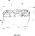
- the block 100 in one embodiment includes an irregularly shaped front portion 190 and a regularly shaped rear portion 195, the front portion including the embossed front face 112 with an irregularly shaped contour 112a with lateral edges 113.
- the block of Figure 10a further includes an interconnecting structure 300 for the connection of a secondary structure (not shown), such as a setback pin, a like concrete block, a veneer block, or a filler block, to the rear face 114 of the concrete block.
- the connecting structure is preferably a dovetail type connection with one or more female connector members 350 provided in a back surface of the wall block and a corresponding number of complementary male connector members provided on the secondary structure to be connected to the back surface 114.
- Filler blocks when attached by way of the interconnecting structure 300 can be used for covering any rearward gap created in an installed condition by the lips 120a, 120b between the block and an adjacent like block.
- a back to back attachment of a pair of like blocks by way of the interconnecting structure 300 also allows for the assembly of a two sided free standing wall.
- the wall and filler blocks may have a different height.
- the wall and filler blocks may have the same or different heights.
- the connecting structure is preferably in the form of a dovetail type connection with one or more male connector members provided on one of the wall and filler blocks and a corresponding number of female connector members provided on the other of the wall and filler blocks.
- the connecting structure may be a separate connector insertable into complementary recesses in the wall and filler blocks.
- any other connecting structure can be used, which is incorporated into or separate from one or both of the wall and filler blocks, as long as the connecting structure renders the wall and filler blocks connectable in a back-to-back orientation.
- the block 100 is provided with an embossed front face 112, which includes at least one false joint 180, which may extend at an angle to the top and bottom faces 116, 118.
- the false joint extends at an angle of about 45 degrees to the top and bottom faces, but other orientations of the false joint at any angle from 0 to 45 degrees are possible.
- the front face can include multiple false joints respectively oriented at different angles to the top and bottom faces.
- the block 100 or 100a can also be provided with irregularly shaped front faces 112 where at least one lateral edge 113 of the front face extends at an angle of up to 45 degrees to the side wall 119.
- the lateral edges 113 of the front face are oriented at an angle of 0 to 45 degrees to the sidewall in order to give the block the appearance of a natural stone.
- One or both of the sidewalls 119 can also be oriented at an angle other than perpendicular to the top and bottom faces 116, 118, for example at an angle of 70 to 110 degrees to the top or bottom face.
- the angled sides of the block be limited to only a front portion 190 of the block, with a rear portion 195 of the block having parallel sidewalls 119 perpendicular to the top and bottom faces 116, 118, for maximum stability of a wall of stacked like blocks.
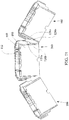
- the blocks 100 with multiple steps 120a, 120b can also be used to build curved wall, whereby the radius of the curvature achievable is determined by the combined protruding length of all the lips 120a, 120b at each end of the block.
Landscapes
- Engineering & Computer Science (AREA)
- Architecture (AREA)
- Civil Engineering (AREA)
- Structural Engineering (AREA)
- Moulds, Cores, Or Mandrels (AREA)
- Retaining Walls (AREA)
- Revetment (AREA)
Description
- The invention relates to concrete blocks, such as wet cast or dry cast concrete blocks for use in the creation of walls, including blocks having an embossed front face. More particularly, the invention relates to concrete blocks with natural stone appearance for use in the creation of curved walls, such as retaining walls.
- Concrete blocks are well known for the use in landscaping applications, particularly retaining walls. Various different block configurations or shapes are known. To allow the assembly of curved walls, concrete retaining wall blocks are usually provided with a rearwardly tapered body with sidewalls that are at an angle of less than 90 degrees to the front face of the block. Stacking such blocks side by side with the angled sidewalls of adjacent blocks engaging one another results in a convexly curved wall. Concave curvatures are obtained by stacking the blocks side by side with the front edges touching, while the tapered rear ends are spaced apart. This provides significant flexibility in the creation of curved walls the radius of curvature of the wall being limited solely by the angle of the sidewalls relative to the front face. However, tapered blocks and walls built with such blocks have several drawbacks.
- Straight walls built with stacked blocks of tapered shape have a substantially continuous front face, but include a pattern of multiple gaps in the back face of the wall, due to the angled sidewalls. In fact, even curved walls with a curvature less than the maximum convex curvature allowed by the taper of the blocks will always include this pattern of gaps. Consequently, tapered blocks cannot be used to build freestanding walls, since the appearance of the rear wall will be very different from the front face and will not be aesthetically pleasing due to the pattern of gaps. A freestanding wall with natural appearance on both sides is not achievable with tapered blocks. Thus, a wall block system for building freestanding curved walls is desired, wherein all sides are continuous and have a natural stone appearance.
- The retaining capacity of a retaining wall is determined in part by the mass of the wall. However, the gaps formed in the rear surface of walls made with tapered blocks significantly reduce the overall mass of the wall. Thus, a wall blocks system for freestanding curved walls is desired, which maximizes the mass of the wall and minimizes any gaps between laterally adjacent wall blocks.
- Molding dry cast tapered blocks with converging side walls and an embossed front face is challenging due to the need for stripping the compressed block from the mold. Dry casting uses a no slope concrete mixture which is filled into a mold cavity and compressed to sufficiently pre-consolidate the block to permit handling of the block prior to curing of the concrete mixture. After pre-consolidation, the block is stripped from the mold and transported to a curing station for curing of the concrete mixture. Stripping of the block is achieved by pushing it out of the mold with a stripper shoe which has a dual function. The stripper shoe is used during pre-consolidation to compress the dry cast concrete mixture. After pre-consolidation, the stripper shoe is used for forcing the pre-consolidated block from the mold. To produce blocks with an embossed surface structure or pattern on the front face, the stripper shoe is provided on its dry cast mixture engaging face with a negative of the three-dimensional surface structure to be produced on the block face during pre-consolidation.
- Stripping the pre-consolidated block by pushing it from the mold requires a clear path for the block through the mold, which mandates the use of movable mold walls in the manufacture of tapered, embossed blocks. To facilitate handling and stacking of pre-consolidated embossed blocks and especially to minimize damage to the embossed front face during curing, the embossed blocks are usually manufactured with the front and rear faces oriented up and down in the mold, respectively. That means the sidewalls of the mold must be movable from the angled position required for the shaping of the tapered shape of the block, in order to provide a clear path of the block through the mold. It is also possible to cast a block assembly consisting of a support block connectable with a face block as disclosed in
US2007/0292216 . Thus, embossed wall blocks for the assembly of curved walls are desired which are more easily manufactured. - It is now an object of the invention to overcome at least one of the disadvantages associated with known dry cast embossed wall blocks.
- The invention provides a stackable concrete wall block, having a prism shaped body with front and rear faces, in a stacked orientation, top and bottom faces for placement opposite like blocks positioned above and below in a stacked condition of the wall block and at least a pair of side walls for placement opposite a like block placed side by side to the wall block, and a lip protruding from at least one of the sidewalls and coplanar with the front face for spacing the body of the block from the body of a like block placed adjacent thereto. The lateral lip comprises multiple staggered steps, each step defined by two perpendicular walls respectively parallel to the side walls and the rear face of the block. Furthermore, the front face of the block and the lip have an embossed three-dimensional surface structure. The block is preferably a dry cast, embossed concrete block.
- The lip is preferably provided on one or both of the side walls to create lateral spacing between concrete blocks stacked side by side in a wall, while providing the wall with a continuous front face. As is the case with tapered blocks, this spacing allows the assembly of curved walls. However, a prism shaped block with straight side walls and a lip is more easily manufactured than a tapered block with angled side walls, since no movable mold walls are required, when the block is a dry cast block. The lip can be achieved by way of a draw plate which is placed in the mold for filling and compression of the dry cast mixture and is pulled from the mold cavity prior to stripping. The use of draw plates in the manufacture of dry cast concrete blocks is known, but is generally used for the production of three-dimensional structures and/or undercuts on the rear face of the block.
- The lip preferably has a depth which is at the maximum 50% of the overall depth of the block as measured from the front face to the back face and preferably between 5% and 50%, most preferably between 25% and 50%.
- In another preferred embodiment, the dry cast concrete block further includes a connecting structure for connection of a secondary structure, such as a setback pin, a like concrete block, a veneer block, or a filler block to the rear face of the concrete block. Filler blocks are used for covering any rearward gap created in an installed condition by the lip between the block and an adjacent like block. A back to back attachment of a pair of like blocks by way of the connecting structure allows for the assembly of a two sided wall. The connecting structure is preferably a dovetail type connection with one or more female connector members provided in a back surface of the wall block and a corresponding number of complementary male connector members provided on the secondary structure to be connected to the back surface.
- In a further embodiment, the invention provides a set of dry cast concrete blocks including a wall block, a filler block and a connecting structure for connecting the wall and filler blocks in a back-to-back arrangement. The wall block preferably has a prism shaped body with front and rear faces, in a stacked orientation, top and bottom faces for placement opposite like blocks positioned above and below in a stacked condition of the wall block and at least a pair of side walls for placement opposite a like block placed side by side to the wall block, and a lip protruding from at least one of the sidewalls and coplanar with the front face for spacing the body of the block from the body of a like block placed adjacent thereto. Preferably, the front face of the block and the lip have a three-dimensional surface structure, and the filler block has a prism shaped body with generally front, rear, top and bottom faces and generally parallel side walls.
- In a preferred embodiment of the set of concrete blocks, the wall block has an overall width X, n protruding lips, with n=1 or 2 and each lip having a protruding width Y, the wall and filler blocks have the same depth and the overall width of the filler block is between X and X-2nY. The wall and filler blocks may have a different height.
- In another preferred embodiment of the set of concrete blocks, the wall block has an overall width X, n protruding lips, with n=1 or 2 and each lip has a protruding width Y and a depth B. The wall block has a depth A and the filler block has a depth C and the overall width of the filler block is between X and X-n(Y+YC/A-B). The wall and filler blocks may have a different height.
- The connecting structure is preferably in the form of a dovetail type connection with one or more male connector members provided on one of the wall and filler blocks and a corresponding number of female connector members provided on the other of the wall and filler block. Alternatively, the connecting structure may be a separate connector insertable into complementary recesses in the wall and filler blocks. However, any other connecting structure can be used, which is incorporated into or separate from one or both of the wall and filler blocks, as long as the connecting structure renders the wall and filler blocks connectable in a back-to-back orientation.
- The invention will now be further described by way of exemplary embodiments and with reference to the attached drawings, wherein,
-
Fig. 1 is a perspective view of a pair of wall blocks spaced apart by the lip portion (not covered by the present claims); -
Fig. 2 is a perspective view of a pair of wall blocks as shown inFig. 1 , but positioned to touch at the lip and at the rear edge, to form an angled arrangement; -
Fig. 3 is a perspective view of a wall block and a filler block in separation and when engaged (not covered by the present claims); -
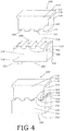
Fig. 4 is a perspective view of a wall and filler block combination as shown inFig. 3 , with the filler block having the same length as the wall block; -
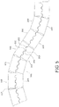
Fig. 5 is a schematic illustration of a curved wall assembled with the set of wall and filler blocks ofFig. 3 ; -
Fig. 6 is a schematic illustration of a curved wall assembled with a the set of wall and filler blocks similar in construction as the set ofFig. 3 , but with the blocks being longer; -
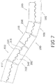
Fig. 7 is a schematic illustration of a curved wall assembled with the different sets of wall and filler blocks ofFigs. 5 and6 (not covered by the present claims); -
Fig. 8 is a schematic illustration of a straight wall assembled with the set of wall and filler blocks ofFig. 4 ; -
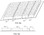
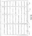
Figs. 9a to 9c are perspective, front elevation and top plan views of a mold frame arrangement for the dry casting of a set of short and long wall and filler blocks (not covered by the present claims); -
Figs. 10a to 10d are perspective, bottom plan, front plan and end elevation views of a wall block with a stepped lip; -
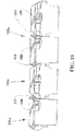
Fig. 11 is a schematic illustration of a curved wall assembled with the wall blocks ofFigs. 10a to 10d ; -
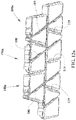
Figs. 12a and12b are a front and top perspective view and a front plan view of a partial wall including seven (7) stacked blocks in accordance with one aspect of the invention; and -
Fig. 13 is a top plan view of the first row of blocks of the partial wall shown inFigs. 12a and12b . - The present application is directed to a wall block for use in retaining walls or freestanding walls, preferably a cast concrete block, more preferably a dry cast, embossed concrete block.
- In an embodiment not covered by the present scope of the claims as illustrated in
Figs. 1 and 2 , thewall block 100 includes, a prism shapedbody 110 with afront face 112, arear face 114, top and bottom faces 116 and 118 and generallyparallel side walls 119. Thewall block 100 further includes aprotruding lip 120 on at least one of theside walls 119, whichlip 120 protrudes from theside wall 119 and is coplanar with thefront face 112. Thelip 120 can be provided on either one or both of theside walls 119. The spacing created by thelips 120 allows the assembly of straight walls as shown inFig. 1 or curved walls as shown inFig. 2 , by arranging the wall blocks in such a way that terminal edges of the block at thelip 120 and therear face 114 touch the respective edges of an adjacent wall block. The protruding length of thelips 120 determines the radius of curvature which can be achieved by placement of the wall blocks 100 side by side in wall with thelips 120 and thebodies 110 of adjacent blocks touching (seeFigs. 5-7 ). The larger the protruding width of the lips, the smaller the minimum radius achievable. Moreover, the shorter the length of thewall block 100, the smaller the minimum radius achievable. - In the installed condition of the
wall block 100, wherein thewall block 100 is stacked with like wall blocks 100 into a wall, thelip 120 provides for spacing between thebodies 110 of adjacent wall blocks 100 placed side by side, while providing the resulting wall with a continuous front surface, as shown inFig. 1 . Thefront face 112 of the block, which extends over thelip 120, preferably has an embossed three-dimensional surface structure. Preferably thefront face 112 is embossed with a surface structure, which provides thewall block 100 and any wall assembled with such wall blocks with the appearance of natural stone. This feature will be described in more detail further below with reference toFigs. 10-13 . - The
lip 120 can be provided on either one or both of theside walls 119, preferably both, to create bi-lateral spacing between thebodies 110 of wall blocks 100 stacked side by side in a straight wall (seeFig. 1 ), while providing the wall with a continuous front surface. As is the case with tapered blocks, this spacing allows the assembly of curved walls, by arranging the wall blocks in such a way that terminal edges of the front and rear faces 112, 114 of adjacent wall blocks 100 are in engagement (seeFig. 2 ). - A
wall block 100 with a prism shapedbody 110 withparallel side walls 119 is more easily manufactured by dry casting than known, tapered blocks, since no movable mold walls are required. - In another embodiment not covered by the present claims as illustrated in the Figures, the dry
cast wall block 100 further includes a connectingstructure 300 for connection of a secondary structure to therear face 114 of thewall block 100. The secondary structure can be a setback pin, a like block, a different block, or a veneer. The different block is preferably afiller block 200 as shown inFigs. 3 and4 for covering any rearward gap created in an installed condition by the lip between the block and an adjacent like block. The connectingstructure 300 includes at least one pair of interconnecting protruding and recessed elements, most preferably in the shape of a dovetail arrangement (seeFigs. 3-8 ), one of the elements being incorporated into therear face 114 of thewall block 100 and the other one into the secondary structure. The connecting structure preferably includes multiple alternating protruding and recessedelements Figs. 3 and4 . Thefiller block 200 is provided for covering any rearward gap created by thelip 120 between thewall block 100 and an adjacent likeblock 100 in the installed condition. When the wall blocks are installed in a curved configuration, the length of the filler block must be less than the length of the wall block (seeFigs. 3 and5-7 ), while in a straight configuration the filler block must have the same length as the wall block (seeFigs. 4 and8 ). - An embodiment of a
filler block 200 not covered by the present claims is illustrated at different lengths inFigs. 3 and4 . Thefiller block 200 includes a prism shapedbody 210 with afront face 212, arear face 214, top and bottom faces 216 and 218 and generallyparallel side walls 219. Thefiller block 200 further includes a connectingstructure 330 which interlocks with the connectingstructure 300 on thewall block 100 for connection of the filler block to therear face 114 of thewall block 100. The connectingstructures - In a further embodiment as illustrated in the bottom portion of
Figs. 3 and4 , there is provided a set of dry cast concrete blocks including awall block 100 and afiller block 200. Thewall block 100 has a prism shapedbody 110 with an embossedfront face 112 and generally planar rear, top and bottom faces 114, 116, 118 and generallyparallel side walls 119, and aprotruding lip 120 extending from at least one of the sidewalls and coplanar with thefront face 112 for spacing thebody 110 of the wall block 100 from the body of a like block placed adjacent thereto, while providing a continuous front surface. Thefront face 112 of thewall block 100 and thelip 120 have a three-dimensional surface structure embossed into the front surface by the stripper shoe in the dry cast molding process. The three dimensional structure preferably provides the wall block with afront face 112 having the appearance of natural stone. Thefiller block 200 has abody 210 shaped as a rectangular prism and having afront face 212, arear face 214, top and bottom faces 216, 218 and generallyparallel side walls 219. Thefiller block 200 preferably has a three-dimensional surface structure embossed into thefront surface 212 by the stripper shoe in the dry cast molding process. The three dimensional structure preferably provides thefiller block 200 with afront face 212 having the appearance of natural stone. Thewall block 100 further includes a connectingstructure 300 and thefiller block 200 of the set of blocks includes a connectingstructure 330 for connecting the wall and filler blocks in a back-to-back arrangement. - A pair of interconnected wall and filler blocks 100, 200 is illustrated in each of
Figs. 3 and4 . In each pair, the interconnectingstructure protrusions recesses protrusion 310 in therear face 114 of thewall block 100 engages arecess 350 in therear face 214 of thefiller block 200 and aconnector 340 in therear face 214 of thefiller block 200 engages arecess 320 in therear face 114 in thewall block 100. - The protruding length Y of the
lips 120 determines the radius of curvature which can be achieved by placement of the wall blocks 100 side by side in a wall with thelips 120 and thebodies 110 ofadjacent blocks 100 being in engagement. The larger the protruding width Y, the smaller the minimum radius achievable. An angle a is enclosed by theside wall 119 of thewall block 100 and animaginary line 400 connecting the free end 121 of the protrudinglip 120 with theterminal edge 115 of therear wall 114. This angle is the minimum angle at which adjacent wall blocks can be placed without forming a gap between the blocks at thefront face 112. Of course, wall blocks 100 can also be placed side by side in straight alignment to form a straight wall, in which case the protrudinglips 120 are in engagement, but the blocks do not touch at therear face 114, resulting in a space between adjacent wall blocks 100 at therear face 114. In order to provide the straight wall with continuous front and rear surfaces, filler blocks 200 are used which have the same overall width X as the wall blocks 100, as shown inFigs. 4 and8 . To achieve a curved wall, the wall blocks 100 are placed side by side with thelips 120 in engagement, while thelateral edges 115 of the rear faces 114 are placed closer to one another as in the straight orientation. In a curved wall of minimum radius, thelateral edges 115 of the rear faces 114 ofadjacent blocks 100 are in engagement and the blocks are placed at the angle a relative to one another. In order to provide the wall with a continuous rear surface, the width of the filler blocks 200 must then be adapted to fit within theimaginary lines 400 defined on each side of the associatedwall block 100 by the angle a, as illustrated inFig. 4 . As will be apparent, the overall width of thefiller block 200 then not only depends on the angle a, but also on the depth C of thefiller block 200, since the larger the depth, the shorter the overall length required for the block fitting between theimaginary lines 400. The length of thefiller block 200 is then determined by the overall width X of thewall block 100, the protruding width Y of thelips 120, the depth B of thelips 120, the depth A of thewall block 100 and the depth C of thefiller block 200. Since the angle a is enclosed between theimaginary line 400 and the side wall is the same for both thewall block 100 and thefiller block 200, the minimum length D of thefiller block 200, which is required for the filler blocks to form a continuous back wall at the smallest radius achievable, can be calculated according to the formula D = X-n(Y+YC/A-B), wherein n is 1 or 2 and defines the number oflips 120 included in thewall block 100, X is the length of thewall block 100, A is the depth of thewall block 100, B is the depth of thelip 120, C is the depth of thefiller block 200, Y is the length of thelip 120 and D is the length of thefiller block 200. Thus, the length D of the filler block can vary between X (for straight walls) and X-n(Y+YC/A-B) (for a curved wall of minimum radius, as shown inFig. 5 ). - Casting of the
lip 120 can be achieved by way of a draw plate 140 (see schematically inFig. 9b ), which is placed in the mold for the wall block. The draw plate is left in the mold for the filling of the mold and compression of the dry cast mixture in the mold and is pulled from the mold cavity prior to stripping of the block. The use of draw plates in the manufacture of dry cast concrete blocks is known. - The
lip 120 preferably has a depth B, measured in a direction parallel to the associatedside wall 119, which is a maximum of 50%, preferably between 50% and 5%, most preferably between 50% and 25% of the overall depth A of thewall block 100 as measured from thefront face 112 to the back face 114 (seeFig. 3 ). The larger the depth of thelip 120, the wider agap 117 between the front faces 112 of adjacent stackedblocks 100 in a curved wall. Thus, in order to minimize thegap 117, it would be preferable to minimize the depth of thelip 120. Yet, the smaller the depth of thelip 120, the harder it is to manufacture theblock 100 by dry casting, since thelip 120 may brake or sag during or after demolding and prior to complete setting of the block. Moreover, the minimum radius achievable withstacked blocks 100 including thelip 120 is determined by the protruding length Y, or overhang, of thelip 120, which is the distance thelip 120 protrudes laterally outward from thesidewall 119 of theblock 100. The larger the overhang created by thelip 120, the smaller the minimum radius achievable. However, the larger the overhang, the higher the risk of thelip 120 braking or sagging during or after demolding. Consequently, the range of radius achievable by adding asingle lip 120 on each side of theblock 100 is limited. - In order to address these limitations to the depth and protruding length of the lip, the invention also provides variant of the
block 100 in which a larger total protruding length Y or overhang is achieved by providing a steppedlip 120 including two ormore steps Figs. 10a to 10d . By dividing the total protruding length or overhang of thelip 120 into multiple,staggered steps step sidewall 119 and therear face 114 of theblock 100. The protruding length of each step is preferably the same and equal to the total protruding length of the lip divided by the number of steps. The outermost step is coplanar with the front face. Any additional step is located further back towards therear face 114 and provides a setback or undercut, so that the overall width of the block becomes progressively more narrow with each additional step. By providing the lip with multiple steps, the danger of braking or sagging of the lip during or after demolding is significantly reduced, since the tendency of the lip to brake or sag then becomes directly dependent on the protruding length of the largest step, rather than the overall protruding length of the lip. Since the potential of the lip braking or sagging during or after demolding also directly depends on the depth of the lip, the depth of the outermost step adjacent thefront face 112 is preferably larger than the depth of any subsequent step. Moreover, the protruding length of the outermost step is preferably smaller than the protruding length of any subsequent step. When two steps are provided, the protruding length of the outermost step is preferably less than half the protruding length of the subsequent step. - As illustrated in
Figure 10a , theblock 100 in one embodiment includes an irregularly shapedfront portion 190 and a regularly shapedrear portion 195, the front portion including the embossedfront face 112 with an irregularly shapedcontour 112a withlateral edges 113. The block ofFigure 10a further includes an interconnectingstructure 300 for the connection of a secondary structure (not shown), such as a setback pin, a like concrete block, a veneer block, or a filler block, to therear face 114 of the concrete block. The connecting structure is preferably a dovetail type connection with one or morefemale connector members 350 provided in a back surface of the wall block and a corresponding number of complementary male connector members provided on the secondary structure to be connected to theback surface 114. Filler blocks when attached by way of the interconnectingstructure 300 can be used for covering any rearward gap created in an installed condition by thelips structure 300 also allows for the assembly of a two sided free standing wall. - In one embodiment of the set of concrete blocks for the assembly of curved walls of minimum radius of curvature, the
wall block 100, including the protrudinglips 120, has an overall width X, protrudinglips 120, with n=1 or 2, each lip has a protruding width Y, the wall and filler blocks 100, 200 have the same depth and the overall width of the filler block is between X and X-2nY. The wall and filler blocks may have a different height. - In another embodiment of the set of concrete blocks, the
wall block 100 has an overall width X, including the protrudinglips 120,n protruding lips 120, with n=1 or 2 and each lip having a protruding width Y and a depth B, thewall block 100 has a depth A, thefiller block 200 has a depth C and the overall width of thefiller block 200 is between X and X-n(Y+YC/A-B). The wall and filler blocks may have the same or different heights. - The connecting structure is preferably in the form of a dovetail type connection with one or more male connector members provided on one of the wall and filler blocks and a corresponding number of female connector members provided on the other of the wall and filler blocks. Alternatively, the connecting structure may be a separate connector insertable into complementary recesses in the wall and filler blocks. However, any other connecting structure can be used, which is incorporated into or separate from one or both of the wall and filler blocks, as long as the connecting structure renders the wall and filler blocks connectable in a back-to-back orientation.
- In another embodiment of the
block 100, illustrated inFigures 12 to 13 asblock 100a, theblock 100 is provided with an embossedfront face 112, which includes at least one false joint 180, which may extend at an angle to the top and bottom faces 116, 118. This provides the block with the appearance of a natural stone. In the particular embodiment illustrated, the false joint extends at an angle of about 45 degrees to the top and bottom faces, but other orientations of the false joint at any angle from 0 to 45 degrees are possible. Of course, the front face can include multiple false joints respectively oriented at different angles to the top and bottom faces. - As illustrated in
Figures 12 to 13 , theblock lateral edge 113 of the front face extends at an angle of up to 45 degrees to theside wall 119. Thus, in this embodiment of the block, thelateral edges 113 of the front face are oriented at an angle of 0 to 45 degrees to the sidewall in order to give the block the appearance of a natural stone. One or both of thesidewalls 119 can also be oriented at an angle other than perpendicular to the top and bottom faces 116, 118, for example at an angle of 70 to 110 degrees to the top or bottom face. However, it is preferred that the angled sides of the block be limited to only afront portion 190 of the block, with arear portion 195 of the block havingparallel sidewalls 119 perpendicular to the top and bottom faces 116, 118, for maximum stability of a wall of stacked like blocks. - As shown in
Fig. 11 , theblocks 100 withmultiple steps lips
Claims (14)
- A stackable concrete wall block (100), comprising
a prism shaped body (110) having front and rear faces (112, 114), in a stacked orientation, top and bottom faces (116, 118) for placement opposite like blocks located above or below in a stacked condition of the wall block and at least a pair of side walls (119) for placement opposite a like block placed side by side to the wall block, and
a lateral lip (120) protruding from at least one of the side walls (119) and coplanar with the front face for spacing the body of the wall block from the body of the like block placed side by side thereto, the front face of the block and the lip having an embossed three-dimensional surface structure,
characterized in that the lateral lip comprises multiple staggered steps (120a, 120b), each step defined by two perpendicular walls respectively parallel to the side walls (119) and the rear face (114) of the block (100). - The wall block of claim 1, wherein the lip (120) is provided on both of the side walls to create lateral spacing between the bodies of concrete blocks (100) stacked side by side in a straight wall, while providing the wall with a continuous front face.
- The wall block (100) of claim 1, wherein the lip (120) has a depth, which is at the maximum 50% of the overall depth of the wall block (100) as measured from the front face to the back face.
- The wall block (100) of claim 3, wherein the lip (120) has a depth between 25% and 50% of the overall depth.
- The wall block (100) of claim 1, wherein the protruding length of an outermost step furthest from the side wall (119) is larger than the protruding length of any subsequent step.
- The wall block (100) of claim 5, wherein the protruding length of the outermost step is less than half the protruding length of the subsequent step.
- The wall block (100) of claim 1, further including a connecting structure for connecting a secondary structure to the rear face (114) of the wall block (100).
- The wall block (100) of claim 7, wherein the secondary structure is a setback pin, a like block, a different block, or a veneer.
- The wall block (100) of claim 8, wherein the different block is a filler block (200) for covering any rearward gap created in an installed condition by the lip (120) between the block and an adjacent like block.
- A set of wall blocks, comprising
a wall block (100) according to any one of the claims 1 to 6;
a filler block (200); and
a connecting structure (300, 320, 350) for connecting the wall and filler blocks (100, 200) in a back-to-back arrangement;
the filler block (200) having a right angular prism shaped body with front, rear, top and bottom faces and generally parallel side walls. - The set of wall blocks of claim 10, wherein the wall block (100) has an overall width X, n protruding lips (120), with n=1 or 2 and each lip (120) having a protruding width Y, the wall block (100) has a
depth A, the lip (120) has a depth B, the filler block (200) has a depth C and an overall width of the filler (200)
block is between X and X-n(Y+YC/(A-B)). - The set of wall blocks of claim 11, wherein the overall width of the filler block (200) is X-n(Y+YC/(A-B)).
- The set of wall blocks of claim 10, wherein the front face includes a top edge and a bottom edge respectively oriented towards like blocks stackable above or below the wall block (100) and lateral edges oriented towards like blocks stackable side by side with the wall block (100), at least one of the lateral edges being oriented at an angle of 45 to 90 degrees to the top or bottom edge.
- The set of wall blocks of claim 13, wherein the body includes a top portion adjacent the front face and a bottom portion adjacent the back face, the front face has an irregularly shaped contour, the top portion having the irregularly shaped contour of the front face and the bottom portion having a polygonal cross section.
Priority Applications (1)
| Application Number | Priority Date | Filing Date | Title |
|---|---|---|---|
| PL11851695T PL2655758T3 (en) | 2010-12-21 | 2011-12-21 | Concrete wall block |
Applications Claiming Priority (3)
| Application Number | Priority Date | Filing Date | Title |
|---|---|---|---|
| US201061425407P | 2010-12-21 | 2010-12-21 | |
| US201161555947P | 2011-11-04 | 2011-11-04 | |
| PCT/CA2011/050796 WO2012083457A1 (en) | 2010-12-21 | 2011-12-21 | Concrete wall block |
Publications (3)
| Publication Number | Publication Date |
|---|---|
| EP2655758A1 EP2655758A1 (en) | 2013-10-30 |
| EP2655758A4 EP2655758A4 (en) | 2015-12-30 |
| EP2655758B1 true EP2655758B1 (en) | 2020-03-04 |
Family
ID=46232555
Family Applications (1)
| Application Number | Title | Priority Date | Filing Date |
|---|---|---|---|
| EP11851695.4A Active EP2655758B1 (en) | 2010-12-21 | 2011-12-21 | Concrete wall block |
Country Status (7)
| Country | Link |
|---|---|
| US (1) | US20120151862A1 (en) |
| EP (1) | EP2655758B1 (en) |
| AU (2) | AU2011348981B2 (en) |
| CA (1) | CA2816643C (en) |
| MX (1) | MX347758B (en) |
| PL (1) | PL2655758T3 (en) |
| WO (1) | WO2012083457A1 (en) |
Families Citing this family (5)
| Publication number | Priority date | Publication date | Assignee | Title |
|---|---|---|---|---|
| US9238910B2 (en) * | 2008-08-19 | 2016-01-19 | David I. Jensen | Interlocking wall unit system for constructing a wall on a pre-existing structural grid matrix |
| CN105102725B (en) | 2013-02-20 | 2017-09-19 | 厄斯沃产品有限责任公司 | Prefabricated smooth section on below traffic guardrail, at the top of native wall system |
| AU2018333845B2 (en) * | 2017-09-14 | 2022-12-08 | Jenner Innovation Pty Ltd | System for building a load bearing structure |
| US12053911B2 (en) | 2018-05-14 | 2024-08-06 | Pavestone, LLC | Manufactured retaining wall block with improved false joint |
| US10316485B1 (en) * | 2018-07-17 | 2019-06-11 | Pacific Coast Building Products, Inc. | Retaining wall block |
Citations (1)
| Publication number | Priority date | Publication date | Assignee | Title |
|---|---|---|---|---|
| US5878545A (en) * | 1996-02-03 | 1999-03-09 | Gebhart; Siegfried | Block, in particular shuttering block or standard block |
Family Cites Families (25)
| Publication number | Priority date | Publication date | Assignee | Title |
|---|---|---|---|---|
| GB112084A (en) * | 1917-04-20 | 1917-12-27 | George Edward Clare | Improvements in Building Blocks adapted for use in connection with Various Constructional Parts of Buildings and like Structures. |
| US4123881A (en) * | 1975-02-10 | 1978-11-07 | Muse George B | Wall structure with insulated interfitting blocks |
| US4825619A (en) * | 1986-09-15 | 1989-05-02 | Keystone Retaining Wall Systems, Inc. | Block wall |
| US5044834A (en) * | 1990-07-26 | 1991-09-03 | Graystone Block Co., Inc. | Retaining wall construction and blocks therefor |
| CA2143379A1 (en) * | 1995-02-24 | 1996-08-25 | Bertin Castonguay | Retaining wall system |
| US5788423A (en) * | 1995-09-08 | 1998-08-04 | G.P. Industries, Inc. | Masonry block retaining wall with attached keylock facing panels and method of constructing the same |
| AUPP647298A0 (en) * | 1998-10-13 | 1998-11-05 | Keystone Retaining Wall Systems, Inc. | Retaining wall block |
| US20020054790A1 (en) * | 1999-08-19 | 2002-05-09 | Rockwood Retaining Walls, Inc. | Block with multifaceted bottom surface |
| US6615561B2 (en) * | 2001-06-07 | 2003-09-09 | Keystone Retaining Wall Systems, Inc. | Retaining wall block |
| US7073304B2 (en) * | 2001-10-16 | 2006-07-11 | Hampton Robert D | Corner building block, system and method |
| US20040088929A1 (en) * | 2002-11-12 | 2004-05-13 | Keystone Retaining Wall Systems, Inc. | Landscaping block |
| US20040159065A1 (en) * | 2003-02-17 | 2004-08-19 | Menard, Inc. | Retaining wall block |
| US6821058B1 (en) * | 2003-06-24 | 2004-11-23 | Keystone Retaining Wall Systems, Inc. | Retaining wall block system and connector |
| KR100505836B1 (en) * | 2003-08-28 | 2005-08-02 | 주식회사 제이지비 | Architectural brick |
| US20050241257A1 (en) * | 2004-04-30 | 2005-11-03 | Price Raymond R | Asymmetric retaining wall block |
| US7524144B2 (en) * | 2004-06-22 | 2009-04-28 | Allan Block Corporation | Retaining wall |
| US7497646B2 (en) * | 2004-11-12 | 2009-03-03 | Mortarless Technologies Llc | Extended width retaining wall block |
| EP1812655A2 (en) * | 2004-11-12 | 2007-08-01 | Mortarless Technologies LLC. | Extended width retaining wall block |
| US20090049788A1 (en) * | 2005-11-21 | 2009-02-26 | Thorpe Douglas G | Building block |
| US7410328B2 (en) * | 2006-06-14 | 2008-08-12 | Transpavé Inc. | Concrete block system |
| AU2008266066A1 (en) * | 2007-06-15 | 2008-12-24 | Keystone Retaining Wall Systems, Inc. | Mold box and method of manufacturing a block |
| AU2008265549A1 (en) * | 2007-06-21 | 2008-12-24 | Keystone Retaining Wall Systems, Inc. | Veneers for walls, retaining walls, retaining wall blocks, and the like |
| SE533326C2 (en) * | 2008-08-28 | 2010-08-31 | Epscement Internat Ab | Building elements and method of building exterior walls with said elements |
| WO2011017704A2 (en) * | 2009-08-07 | 2011-02-10 | Garrett Michael D | Deck block |
| US8201376B2 (en) * | 2009-09-03 | 2012-06-19 | Witcher Steve D | Dry-stack masonry system |
-
2011
- 2011-12-21 US US13/332,971 patent/US20120151862A1/en not_active Abandoned
- 2011-12-21 MX MX2013006711A patent/MX347758B/en active IP Right Grant
- 2011-12-21 CA CA2816643A patent/CA2816643C/en active Active
- 2011-12-21 WO PCT/CA2011/050796 patent/WO2012083457A1/en not_active Ceased
- 2011-12-21 EP EP11851695.4A patent/EP2655758B1/en active Active
- 2011-12-21 AU AU2011348981A patent/AU2011348981B2/en not_active Ceased
- 2011-12-21 PL PL11851695T patent/PL2655758T3/en unknown
-
2017
- 2017-09-14 AU AU2017228669A patent/AU2017228669B2/en not_active Ceased
Patent Citations (1)
| Publication number | Priority date | Publication date | Assignee | Title |
|---|---|---|---|---|
| US5878545A (en) * | 1996-02-03 | 1999-03-09 | Gebhart; Siegfried | Block, in particular shuttering block or standard block |
Also Published As
| Publication number | Publication date |
|---|---|
| CA2816643C (en) | 2015-12-01 |
| MX2013006711A (en) | 2013-08-26 |
| AU2017228669B2 (en) | 2019-09-26 |
| EP2655758A1 (en) | 2013-10-30 |
| US20120151862A1 (en) | 2012-06-21 |
| MX347758B (en) | 2017-05-11 |
| AU2011348981B2 (en) | 2017-06-08 |
| AU2011348981A1 (en) | 2013-06-13 |
| CA2816643A1 (en) | 2012-06-28 |
| WO2012083457A1 (en) | 2012-06-28 |
| PL2655758T3 (en) | 2020-09-07 |
| AU2017228669A1 (en) | 2017-10-05 |
| EP2655758A4 (en) | 2015-12-30 |
Similar Documents
| Publication | Publication Date | Title |
|---|---|---|
| AU2017228669B2 (en) | Concrete wall block | |
| US7497646B2 (en) | Extended width retaining wall block | |
| CA2846915C (en) | Irregular trapezoidal building unit and wall structure including same | |
| US10760242B2 (en) | Blocks, block systems and methods of making blocks | |
| CA3000082C (en) | Reversible segmental retaining wall block, molds and methods for manufacturing same, and methods of forming retaining walls with same | |
| CA2533399A1 (en) | Method of making wall block | |
| US11274457B2 (en) | Formliners and methods of use | |
| US8443563B2 (en) | Building block having the appearance of wood shake | |
| US20060101770A1 (en) | Extended width retaining wall block | |
| US20150247328A1 (en) | Building blocks and rear interlock connector therefor | |
| US10087597B2 (en) | Concrete wall block | |
| US20060145050A1 (en) | Multi-block mold and system | |
| US20050284092A1 (en) | Interlocking blocks for construction | |
| CA2531950C (en) | Multiple retaining wall block unit with off-center splitting grooves | |
| US10422101B2 (en) | Blocks and block connectors, block systems and methods of making blocks | |
| US20240401299A1 (en) | Segmented wall and landscaping block systems with lug processes | |
| GB2634455A (en) | System of construction elements for jointless erection of building walls | |
| CN1630762A (en) | Wall Brick Components | |
| HK1104012A (en) | Method of making wall block |
Legal Events
| Date | Code | Title | Description |
|---|---|---|---|
| PUAI | Public reference made under article 153(3) epc to a published international application that has entered the european phase |
Free format text: ORIGINAL CODE: 0009012 |
|
| 17P | Request for examination filed |
Effective date: 20130613 |
|
| AK | Designated contracting states |
Kind code of ref document: A1 Designated state(s): AL AT BE BG CH CY CZ DE DK EE ES FI FR GB GR HR HU IE IS IT LI LT LU LV MC MK MT NL NO PL PT RO RS SE SI SK SM TR |
|
| DAX | Request for extension of the european patent (deleted) | ||
| RA4 | Supplementary search report drawn up and despatched (corrected) |
Effective date: 20151202 |
|
| RIC1 | Information provided on ipc code assigned before grant |
Ipc: E04C 1/00 20060101AFI20151126BHEP Ipc: E04C 1/39 20060101ALI20151126BHEP Ipc: E04B 2/02 20060101ALI20151126BHEP Ipc: E02D 29/02 20060101ALI20151126BHEP |
|
| STAA | Information on the status of an ep patent application or granted ep patent |
Free format text: STATUS: EXAMINATION IS IN PROGRESS |
|
| 17Q | First examination report despatched |
Effective date: 20180123 |
|
| GRAP | Despatch of communication of intention to grant a patent |
Free format text: ORIGINAL CODE: EPIDOSNIGR1 |
|
| STAA | Information on the status of an ep patent application or granted ep patent |
Free format text: STATUS: GRANT OF PATENT IS INTENDED |
|
| INTG | Intention to grant announced |
Effective date: 20190924 |
|
| GRAS | Grant fee paid |
Free format text: ORIGINAL CODE: EPIDOSNIGR3 |
|
| GRAA | (expected) grant |
Free format text: ORIGINAL CODE: 0009210 |
|
| STAA | Information on the status of an ep patent application or granted ep patent |
Free format text: STATUS: THE PATENT HAS BEEN GRANTED |
|
| AK | Designated contracting states |
Kind code of ref document: B1 Designated state(s): AL AT BE BG CH CY CZ DE DK EE ES FI FR GB GR HR HU IE IS IT LI LT LU LV MC MK MT NL NO PL PT RO RS SE SI SK SM TR |
|
| REG | Reference to a national code |
Ref country code: GB Ref legal event code: FG4D |
|
| REG | Reference to a national code |
Ref country code: CH Ref legal event code: EP |
|
| REG | Reference to a national code |
Ref country code: AT Ref legal event code: REF Ref document number: 1240512 Country of ref document: AT Kind code of ref document: T Effective date: 20200315 |
|
| REG | Reference to a national code |
Ref country code: DE Ref legal event code: R096 Ref document number: 602011065432 Country of ref document: DE |
|
| REG | Reference to a national code |
Ref country code: IE Ref legal event code: FG4D |
|
| REG | Reference to a national code |
Ref country code: NL Ref legal event code: FP |
|
| PG25 | Lapsed in a contracting state [announced via postgrant information from national office to epo] |
Ref country code: NO Free format text: LAPSE BECAUSE OF FAILURE TO SUBMIT A TRANSLATION OF THE DESCRIPTION OR TO PAY THE FEE WITHIN THE PRESCRIBED TIME-LIMIT Effective date: 20200604 Ref country code: RS Free format text: LAPSE BECAUSE OF FAILURE TO SUBMIT A TRANSLATION OF THE DESCRIPTION OR TO PAY THE FEE WITHIN THE PRESCRIBED TIME-LIMIT Effective date: 20200304 Ref country code: FI Free format text: LAPSE BECAUSE OF FAILURE TO SUBMIT A TRANSLATION OF THE DESCRIPTION OR TO PAY THE FEE WITHIN THE PRESCRIBED TIME-LIMIT Effective date: 20200304 |
|
| REG | Reference to a national code |
Ref country code: SK Ref legal event code: T3 Ref document number: E 34234 Country of ref document: SK |
|
| PG25 | Lapsed in a contracting state [announced via postgrant information from national office to epo] |
Ref country code: SE Free format text: LAPSE BECAUSE OF FAILURE TO SUBMIT A TRANSLATION OF THE DESCRIPTION OR TO PAY THE FEE WITHIN THE PRESCRIBED TIME-LIMIT Effective date: 20200304 Ref country code: LV Free format text: LAPSE BECAUSE OF FAILURE TO SUBMIT A TRANSLATION OF THE DESCRIPTION OR TO PAY THE FEE WITHIN THE PRESCRIBED TIME-LIMIT Effective date: 20200304 Ref country code: GR Free format text: LAPSE BECAUSE OF FAILURE TO SUBMIT A TRANSLATION OF THE DESCRIPTION OR TO PAY THE FEE WITHIN THE PRESCRIBED TIME-LIMIT Effective date: 20200605 Ref country code: HR Free format text: LAPSE BECAUSE OF FAILURE TO SUBMIT A TRANSLATION OF THE DESCRIPTION OR TO PAY THE FEE WITHIN THE PRESCRIBED TIME-LIMIT Effective date: 20200304 Ref country code: BG Free format text: LAPSE BECAUSE OF FAILURE TO SUBMIT A TRANSLATION OF THE DESCRIPTION OR TO PAY THE FEE WITHIN THE PRESCRIBED TIME-LIMIT Effective date: 20200604 |
|
| REG | Reference to a national code |
Ref country code: LT Ref legal event code: MG4D |
|
| PG25 | Lapsed in a contracting state [announced via postgrant information from national office to epo] |
Ref country code: EE Free format text: LAPSE BECAUSE OF FAILURE TO SUBMIT A TRANSLATION OF THE DESCRIPTION OR TO PAY THE FEE WITHIN THE PRESCRIBED TIME-LIMIT Effective date: 20200304 Ref country code: ES Free format text: LAPSE BECAUSE OF FAILURE TO SUBMIT A TRANSLATION OF THE DESCRIPTION OR TO PAY THE FEE WITHIN THE PRESCRIBED TIME-LIMIT Effective date: 20200304 Ref country code: LT Free format text: LAPSE BECAUSE OF FAILURE TO SUBMIT A TRANSLATION OF THE DESCRIPTION OR TO PAY THE FEE WITHIN THE PRESCRIBED TIME-LIMIT Effective date: 20200304 Ref country code: CZ Free format text: LAPSE BECAUSE OF FAILURE TO SUBMIT A TRANSLATION OF THE DESCRIPTION OR TO PAY THE FEE WITHIN THE PRESCRIBED TIME-LIMIT Effective date: 20200304 Ref country code: IS Free format text: LAPSE BECAUSE OF FAILURE TO SUBMIT A TRANSLATION OF THE DESCRIPTION OR TO PAY THE FEE WITHIN THE PRESCRIBED TIME-LIMIT Effective date: 20200704 Ref country code: RO Free format text: LAPSE BECAUSE OF FAILURE TO SUBMIT A TRANSLATION OF THE DESCRIPTION OR TO PAY THE FEE WITHIN THE PRESCRIBED TIME-LIMIT Effective date: 20200304 Ref country code: PT Free format text: LAPSE BECAUSE OF FAILURE TO SUBMIT A TRANSLATION OF THE DESCRIPTION OR TO PAY THE FEE WITHIN THE PRESCRIBED TIME-LIMIT Effective date: 20200729 Ref country code: SM Free format text: LAPSE BECAUSE OF FAILURE TO SUBMIT A TRANSLATION OF THE DESCRIPTION OR TO PAY THE FEE WITHIN THE PRESCRIBED TIME-LIMIT Effective date: 20200304 |
|
| REG | Reference to a national code |
Ref country code: AT Ref legal event code: MK05 Ref document number: 1240512 Country of ref document: AT Kind code of ref document: T Effective date: 20200304 |
|
| REG | Reference to a national code |
Ref country code: DE Ref legal event code: R097 Ref document number: 602011065432 Country of ref document: DE |
|
| PLBE | No opposition filed within time limit |
Free format text: ORIGINAL CODE: 0009261 |
|
| STAA | Information on the status of an ep patent application or granted ep patent |
Free format text: STATUS: NO OPPOSITION FILED WITHIN TIME LIMIT |
|
| PG25 | Lapsed in a contracting state [announced via postgrant information from national office to epo] |
Ref country code: DK Free format text: LAPSE BECAUSE OF FAILURE TO SUBMIT A TRANSLATION OF THE DESCRIPTION OR TO PAY THE FEE WITHIN THE PRESCRIBED TIME-LIMIT Effective date: 20200304 Ref country code: AT Free format text: LAPSE BECAUSE OF FAILURE TO SUBMIT A TRANSLATION OF THE DESCRIPTION OR TO PAY THE FEE WITHIN THE PRESCRIBED TIME-LIMIT Effective date: 20200304 Ref country code: IT Free format text: LAPSE BECAUSE OF FAILURE TO SUBMIT A TRANSLATION OF THE DESCRIPTION OR TO PAY THE FEE WITHIN THE PRESCRIBED TIME-LIMIT Effective date: 20200304 |
|
| 26N | No opposition filed |
Effective date: 20201207 |
|
| PG25 | Lapsed in a contracting state [announced via postgrant information from national office to epo] |
Ref country code: SI Free format text: LAPSE BECAUSE OF FAILURE TO SUBMIT A TRANSLATION OF THE DESCRIPTION OR TO PAY THE FEE WITHIN THE PRESCRIBED TIME-LIMIT Effective date: 20200304 |
|
| REG | Reference to a national code |
Ref country code: CH Ref legal event code: PL |
|
| PG25 | Lapsed in a contracting state [announced via postgrant information from national office to epo] |
Ref country code: MC Free format text: LAPSE BECAUSE OF FAILURE TO SUBMIT A TRANSLATION OF THE DESCRIPTION OR TO PAY THE FEE WITHIN THE PRESCRIBED TIME-LIMIT Effective date: 20200304 |
|
| PG25 | Lapsed in a contracting state [announced via postgrant information from national office to epo] |
Ref country code: LU Free format text: LAPSE BECAUSE OF NON-PAYMENT OF DUE FEES Effective date: 20201221 |
|
| PG25 | Lapsed in a contracting state [announced via postgrant information from national office to epo] |
Ref country code: CH Free format text: LAPSE BECAUSE OF NON-PAYMENT OF DUE FEES Effective date: 20201231 Ref country code: LI Free format text: LAPSE BECAUSE OF NON-PAYMENT OF DUE FEES Effective date: 20201231 |
|
| PG25 | Lapsed in a contracting state [announced via postgrant information from national office to epo] |
Ref country code: TR Free format text: LAPSE BECAUSE OF FAILURE TO SUBMIT A TRANSLATION OF THE DESCRIPTION OR TO PAY THE FEE WITHIN THE PRESCRIBED TIME-LIMIT Effective date: 20200304 Ref country code: MT Free format text: LAPSE BECAUSE OF FAILURE TO SUBMIT A TRANSLATION OF THE DESCRIPTION OR TO PAY THE FEE WITHIN THE PRESCRIBED TIME-LIMIT Effective date: 20200304 Ref country code: CY Free format text: LAPSE BECAUSE OF FAILURE TO SUBMIT A TRANSLATION OF THE DESCRIPTION OR TO PAY THE FEE WITHIN THE PRESCRIBED TIME-LIMIT Effective date: 20200304 |
|
| PG25 | Lapsed in a contracting state [announced via postgrant information from national office to epo] |
Ref country code: MK Free format text: LAPSE BECAUSE OF FAILURE TO SUBMIT A TRANSLATION OF THE DESCRIPTION OR TO PAY THE FEE WITHIN THE PRESCRIBED TIME-LIMIT Effective date: 20200304 Ref country code: AL Free format text: LAPSE BECAUSE OF FAILURE TO SUBMIT A TRANSLATION OF THE DESCRIPTION OR TO PAY THE FEE WITHIN THE PRESCRIBED TIME-LIMIT Effective date: 20200304 |
|
| P01 | Opt-out of the competence of the unified patent court (upc) registered |
Effective date: 20230609 |
|
| PGFP | Annual fee paid to national office [announced via postgrant information from national office to epo] |
Ref country code: NL Payment date: 20231121 Year of fee payment: 13 |
|
| PGFP | Annual fee paid to national office [announced via postgrant information from national office to epo] |
Ref country code: SK Payment date: 20231128 Year of fee payment: 13 |
|
| PGFP | Annual fee paid to national office [announced via postgrant information from national office to epo] |
Ref country code: GB Payment date: 20231124 Year of fee payment: 13 |
|
| PGFP | Annual fee paid to national office [announced via postgrant information from national office to epo] |
Ref country code: IE Payment date: 20231123 Year of fee payment: 13 Ref country code: FR Payment date: 20231122 Year of fee payment: 13 Ref country code: DE Payment date: 20231121 Year of fee payment: 13 |
|
| PGFP | Annual fee paid to national office [announced via postgrant information from national office to epo] |
Ref country code: PL Payment date: 20231127 Year of fee payment: 13 Ref country code: BE Payment date: 20231121 Year of fee payment: 13 |
|
| REG | Reference to a national code |
Ref country code: DE Ref legal event code: R119 Ref document number: 602011065432 Country of ref document: DE |
|
| REG | Reference to a national code |
Ref country code: NL Ref legal event code: MM Effective date: 20250101 |
|
| REG | Reference to a national code |
Ref country code: SK Ref legal event code: MM4A Ref document number: E 34234 Country of ref document: SK Effective date: 20241221 |
|
| GBPC | Gb: european patent ceased through non-payment of renewal fee |
Effective date: 20241221 |
|
| PG25 | Lapsed in a contracting state [announced via postgrant information from national office to epo] |
Ref country code: NL Free format text: LAPSE BECAUSE OF NON-PAYMENT OF DUE FEES Effective date: 20250101 |
|
| REG | Reference to a national code |
Ref country code: BE Ref legal event code: MM Effective date: 20241231 |
|
| PG25 | Lapsed in a contracting state [announced via postgrant information from national office to epo] |
Ref country code: DE Free format text: LAPSE BECAUSE OF NON-PAYMENT OF DUE FEES Effective date: 20250701 |
|
| PG25 | Lapsed in a contracting state [announced via postgrant information from national office to epo] |
Ref country code: BE Free format text: LAPSE BECAUSE OF NON-PAYMENT OF DUE FEES Effective date: 20241231 Ref country code: GB Free format text: LAPSE BECAUSE OF NON-PAYMENT OF DUE FEES Effective date: 20241221 |
|
| PG25 | Lapsed in a contracting state [announced via postgrant information from national office to epo] |
Ref country code: FR Free format text: LAPSE BECAUSE OF NON-PAYMENT OF DUE FEES Effective date: 20241231 |
|
| PG25 | Lapsed in a contracting state [announced via postgrant information from national office to epo] |
Ref country code: IE Free format text: LAPSE BECAUSE OF NON-PAYMENT OF DUE FEES Effective date: 20241221 |
|
| PG25 | Lapsed in a contracting state [announced via postgrant information from national office to epo] |
Ref country code: SK Free format text: LAPSE BECAUSE OF NON-PAYMENT OF DUE FEES Effective date: 20241221 |