EP2654582B1 - Microneedle patch applicator - Google Patents
Microneedle patch applicator Download PDFInfo
- Publication number
- EP2654582B1 EP2654582B1 EP11850496.8A EP11850496A EP2654582B1 EP 2654582 B1 EP2654582 B1 EP 2654582B1 EP 11850496 A EP11850496 A EP 11850496A EP 2654582 B1 EP2654582 B1 EP 2654582B1
- Authority
- EP
- European Patent Office
- Prior art keywords
- applicator
- microneedle patch
- microneedle
- plate
- retracted position
- Prior art date
- Legal status (The legal status is an assumption and is not a legal conclusion. Google has not performed a legal analysis and makes no representation as to the accuracy of the status listed.)
- Not-in-force
Links
- 230000007246 mechanism Effects 0.000 claims description 54
- 238000003032 molecular docking Methods 0.000 claims description 23
- 230000006835 compression Effects 0.000 claims description 20
- 238000007906 compression Methods 0.000 claims description 20
- 238000004806 packaging method and process Methods 0.000 claims description 11
- 239000012867 bioactive agent Substances 0.000 claims description 5
- 238000007373 indentation Methods 0.000 claims description 5
- 230000004044 response Effects 0.000 claims description 4
- 230000008878 coupling Effects 0.000 claims description 3
- 238000010168 coupling process Methods 0.000 claims description 3
- 238000005859 coupling reaction Methods 0.000 claims description 3
- 210000003491 skin Anatomy 0.000 description 49
- 239000003795 chemical substances by application Substances 0.000 description 31
- 239000000463 material Substances 0.000 description 13
- -1 vaccines Substances 0.000 description 10
- 229920000858 Cyclodextrin Polymers 0.000 description 7
- 102000003982 Parathyroid hormone Human genes 0.000 description 7
- 108090000445 Parathyroid hormone Proteins 0.000 description 7
- 239000000199 parathyroid hormone Substances 0.000 description 7
- 238000007789 sealing Methods 0.000 description 7
- 230000001954 sterilising effect Effects 0.000 description 7
- 238000004659 sterilization and disinfection Methods 0.000 description 7
- KRKNYBCHXYNGOX-UHFFFAOYSA-N citric acid Chemical compound OC(=O)CC(O)(C(O)=O)CC(O)=O KRKNYBCHXYNGOX-UHFFFAOYSA-N 0.000 description 6
- 238000000034 method Methods 0.000 description 6
- 229960001319 parathyroid hormone Drugs 0.000 description 6
- 239000004033 plastic Substances 0.000 description 6
- 229920003023 plastic Polymers 0.000 description 6
- 239000003814 drug Substances 0.000 description 5
- 230000008569 process Effects 0.000 description 5
- 239000000758 substrate Substances 0.000 description 5
- 229920001450 Alpha-Cyclodextrin Polymers 0.000 description 4
- 239000001116 FEMA 4028 Substances 0.000 description 4
- QAOWNCQODCNURD-UHFFFAOYSA-N Sulfuric acid Chemical compound OS(O)(=O)=O QAOWNCQODCNURD-UHFFFAOYSA-N 0.000 description 4
- WNLRTRBMVRJNCN-UHFFFAOYSA-N adipic acid Chemical compound OC(=O)CCCCC(O)=O WNLRTRBMVRJNCN-UHFFFAOYSA-N 0.000 description 4
- 229940043377 alpha-cyclodextrin Drugs 0.000 description 4
- 229960004853 betadex Drugs 0.000 description 4
- 239000002131 composite material Substances 0.000 description 4
- 230000000994 depressogenic effect Effects 0.000 description 4
- 229940079593 drug Drugs 0.000 description 4
- 229940088597 hormone Drugs 0.000 description 4
- 239000005556 hormone Substances 0.000 description 4
- ROBFUDYVXSDBQM-UHFFFAOYSA-N hydroxymalonic acid Chemical compound OC(=O)C(O)C(O)=O ROBFUDYVXSDBQM-UHFFFAOYSA-N 0.000 description 4
- NOESYZHRGYRDHS-UHFFFAOYSA-N insulin Chemical compound N1C(=O)C(NC(=O)C(CCC(N)=O)NC(=O)C(CCC(O)=O)NC(=O)C(C(C)C)NC(=O)C(NC(=O)CN)C(C)CC)CSSCC(C(NC(CO)C(=O)NC(CC(C)C)C(=O)NC(CC=2C=CC(O)=CC=2)C(=O)NC(CCC(N)=O)C(=O)NC(CC(C)C)C(=O)NC(CCC(O)=O)C(=O)NC(CC(N)=O)C(=O)NC(CC=2C=CC(O)=CC=2)C(=O)NC(CSSCC(NC(=O)C(C(C)C)NC(=O)C(CC(C)C)NC(=O)C(CC=2C=CC(O)=CC=2)NC(=O)C(CC(C)C)NC(=O)C(C)NC(=O)C(CCC(O)=O)NC(=O)C(C(C)C)NC(=O)C(CC(C)C)NC(=O)C(CC=2NC=NC=2)NC(=O)C(CO)NC(=O)CNC2=O)C(=O)NCC(=O)NC(CCC(O)=O)C(=O)NC(CCCNC(N)=N)C(=O)NCC(=O)NC(CC=3C=CC=CC=3)C(=O)NC(CC=3C=CC=CC=3)C(=O)NC(CC=3C=CC(O)=CC=3)C(=O)NC(C(C)O)C(=O)N3C(CCC3)C(=O)NC(CCCCN)C(=O)NC(C)C(O)=O)C(=O)NC(CC(N)=O)C(O)=O)=O)NC(=O)C(C(C)CC)NC(=O)C(CO)NC(=O)C(C(C)O)NC(=O)C1CSSCC2NC(=O)C(CC(C)C)NC(=O)C(NC(=O)C(CCC(N)=O)NC(=O)C(CC(N)=O)NC(=O)C(NC(=O)C(N)CC=1C=CC=CC=1)C(C)C)CC1=CN=CN1 NOESYZHRGYRDHS-UHFFFAOYSA-N 0.000 description 4
- 238000003860 storage Methods 0.000 description 4
- 210000000434 stratum corneum Anatomy 0.000 description 4
- 239000000126 substance Substances 0.000 description 4
- 235000000346 sugar Nutrition 0.000 description 4
- 102000003951 Erythropoietin Human genes 0.000 description 3
- 108090000394 Erythropoietin Proteins 0.000 description 3
- LFQSCWFLJHTTHZ-UHFFFAOYSA-N Ethanol Chemical compound CCO LFQSCWFLJHTTHZ-UHFFFAOYSA-N 0.000 description 3
- 102000018997 Growth Hormone Human genes 0.000 description 3
- 108010051696 Growth Hormone Proteins 0.000 description 3
- OKKJLVBELUTLKV-UHFFFAOYSA-N Methanol Chemical compound OC OKKJLVBELUTLKV-UHFFFAOYSA-N 0.000 description 3
- ZMXDDKWLCZADIW-UHFFFAOYSA-N N,N-Dimethylformamide Chemical compound CN(C)C=O ZMXDDKWLCZADIW-UHFFFAOYSA-N 0.000 description 3
- OFOBLEOULBTSOW-UHFFFAOYSA-N Propanedioic acid Natural products OC(=O)CC(O)=O OFOBLEOULBTSOW-UHFFFAOYSA-N 0.000 description 3
- DNIAPMSPPWPWGF-UHFFFAOYSA-N Propylene glycol Chemical compound CC(O)CO DNIAPMSPPWPWGF-UHFFFAOYSA-N 0.000 description 3
- 230000009471 action Effects 0.000 description 3
- 239000000853 adhesive Substances 0.000 description 3
- 230000001070 adhesive effect Effects 0.000 description 3
- 238000004873 anchoring Methods 0.000 description 3
- KBZOIRJILGZLEJ-LGYYRGKSSA-N argipressin Chemical compound C([C@H]1C(=O)N[C@@H](CCC(N)=O)C(=O)N[C@@H](CC(N)=O)C(=O)N[C@@H](CSSC[C@@H](C(N[C@@H](CC=2C=CC(O)=CC=2)C(=O)N1)=O)N)C(=O)N1[C@@H](CCC1)C(=O)N[C@@H](CCCN=C(N)N)C(=O)NCC(N)=O)C1=CC=CC=C1 KBZOIRJILGZLEJ-LGYYRGKSSA-N 0.000 description 3
- IDLFZVILOHSSID-OVLDLUHVSA-N corticotropin Chemical compound C([C@@H](C(=O)N[C@@H](CO)C(=O)N[C@@H](CCSC)C(=O)N[C@@H](CCC(O)=O)C(=O)N[C@@H](CC=1NC=NC=1)C(=O)N[C@@H](CC=1C=CC=CC=1)C(=O)N[C@@H](CCCNC(N)=N)C(=O)N[C@@H](CC=1C2=CC=CC=C2NC=1)C(=O)NCC(=O)N[C@@H](CCCCN)C(=O)N1[C@@H](CCC1)C(=O)N[C@@H](C(C)C)C(=O)NCC(=O)N[C@@H](CCCCN)C(=O)N[C@@H](CCCCN)C(=O)N[C@@H](CCCNC(N)=N)C(=O)N[C@@H](CCCNC(N)=N)C(=O)N1[C@@H](CCC1)C(=O)N[C@@H](C(C)C)C(=O)N[C@@H](CCCCN)C(=O)N[C@@H](C(C)C)C(=O)N[C@@H](CC=1C=CC(O)=CC=1)C(=O)N1[C@@H](CCC1)C(=O)N[C@@H](CC(N)=O)C(=O)NCC(=O)N[C@@H](C)C(=O)N[C@@H](CCC(O)=O)C(=O)N[C@@H](CC(O)=O)C(=O)N[C@@H](CCC(O)=O)C(=O)N[C@@H](CO)C(=O)N[C@@H](C)C(=O)N[C@@H](CCC(O)=O)C(=O)N[C@@H](C)C(=O)N[C@@H](CC=1C=CC=CC=1)C(=O)N1[C@@H](CCC1)C(=O)N[C@@H](CC(C)C)C(=O)N[C@@H](CCC(O)=O)C(=O)N[C@@H](CC=1C=CC=CC=1)C(O)=O)NC(=O)[C@@H](N)CO)C1=CC=C(O)C=C1 IDLFZVILOHSSID-OVLDLUHVSA-N 0.000 description 3
- 238000012377 drug delivery Methods 0.000 description 3
- 229940105423 erythropoietin Drugs 0.000 description 3
- 150000004676 glycans Chemical class 0.000 description 3
- 230000003116 impacting effect Effects 0.000 description 3
- 229910052751 metal Inorganic materials 0.000 description 3
- 239000002184 metal Substances 0.000 description 3
- 229920001282 polysaccharide Polymers 0.000 description 3
- 239000005017 polysaccharide Substances 0.000 description 3
- OXCMYAYHXIHQOA-UHFFFAOYSA-N potassium;[2-butyl-5-chloro-3-[[4-[2-(1,2,4-triaza-3-azanidacyclopenta-1,4-dien-5-yl)phenyl]phenyl]methyl]imidazol-4-yl]methanol Chemical compound [K+].CCCCC1=NC(Cl)=C(CO)N1CC1=CC=C(C=2C(=CC=CC=2)C2=N[N-]N=N2)C=C1 OXCMYAYHXIHQOA-UHFFFAOYSA-N 0.000 description 3
- 108090000765 processed proteins & peptides Proteins 0.000 description 3
- 108090000623 proteins and genes Proteins 0.000 description 3
- 239000003488 releasing hormone Substances 0.000 description 3
- 239000002023 wood Substances 0.000 description 3
- HDTRYLNUVZCQOY-UHFFFAOYSA-N α-D-glucopyranosyl-α-D-glucopyranoside Natural products OC1C(O)C(O)C(CO)OC1OC1C(O)C(O)C(O)C(CO)O1 HDTRYLNUVZCQOY-UHFFFAOYSA-N 0.000 description 2
- NPOAOTPXWNWTSH-UHFFFAOYSA-N 3-hydroxy-3-methylglutaric acid Chemical compound OC(=O)CC(O)(C)CC(O)=O NPOAOTPXWNWTSH-UHFFFAOYSA-N 0.000 description 2
- JOOXCMJARBKPKM-UHFFFAOYSA-N 4-oxopentanoic acid Chemical compound CC(=O)CCC(O)=O JOOXCMJARBKPKM-UHFFFAOYSA-N 0.000 description 2
- 108090000932 Calcitonin Gene-Related Peptide Proteins 0.000 description 2
- 102000004414 Calcitonin Gene-Related Peptide Human genes 0.000 description 2
- 102400000739 Corticotropin Human genes 0.000 description 2
- 101800000414 Corticotropin Proteins 0.000 description 2
- RGHNJXZEOKUKBD-SQOUGZDYSA-N D-gluconic acid Chemical compound OC[C@@H](O)[C@@H](O)[C@H](O)[C@@H](O)C(O)=O RGHNJXZEOKUKBD-SQOUGZDYSA-N 0.000 description 2
- SHZGCJCMOBCMKK-UHFFFAOYSA-N D-mannomethylose Natural products CC1OC(O)C(O)C(O)C1O SHZGCJCMOBCMKK-UHFFFAOYSA-N 0.000 description 2
- SRBFZHDQGSBBOR-IOVATXLUSA-N D-xylopyranose Chemical compound O[C@@H]1COC(O)[C@H](O)[C@H]1O SRBFZHDQGSBBOR-IOVATXLUSA-N 0.000 description 2
- 108010000437 Deamino Arginine Vasopressin Proteins 0.000 description 2
- 229920001353 Dextrin Polymers 0.000 description 2
- 239000004375 Dextrin Substances 0.000 description 2
- IAYPIBMASNFSPL-UHFFFAOYSA-N Ethylene oxide Chemical compound C1CO1 IAYPIBMASNFSPL-UHFFFAOYSA-N 0.000 description 2
- VZCYOOQTPOCHFL-OWOJBTEDSA-N Fumaric acid Chemical compound OC(=O)\C=C\C(O)=O VZCYOOQTPOCHFL-OWOJBTEDSA-N 0.000 description 2
- PEDCQBHIVMGVHV-UHFFFAOYSA-N Glycerine Chemical compound OCC(O)CO PEDCQBHIVMGVHV-UHFFFAOYSA-N 0.000 description 2
- AEMRFAOFKBGASW-UHFFFAOYSA-N Glycolic acid Chemical compound OCC(O)=O AEMRFAOFKBGASW-UHFFFAOYSA-N 0.000 description 2
- 102000004269 Granulocyte Colony-Stimulating Factor Human genes 0.000 description 2
- 108010017080 Granulocyte Colony-Stimulating Factor Proteins 0.000 description 2
- 108010017213 Granulocyte-Macrophage Colony-Stimulating Factor Proteins 0.000 description 2
- 102100039620 Granulocyte-macrophage colony-stimulating factor Human genes 0.000 description 2
- 102000008100 Human Serum Albumin Human genes 0.000 description 2
- 108091006905 Human Serum Albumin Proteins 0.000 description 2
- VEXZGXHMUGYJMC-UHFFFAOYSA-N Hydrochloric acid Chemical compound Cl VEXZGXHMUGYJMC-UHFFFAOYSA-N 0.000 description 2
- 239000004354 Hydroxyethyl cellulose Substances 0.000 description 2
- 229920000663 Hydroxyethyl cellulose Polymers 0.000 description 2
- 229920001479 Hydroxyethyl methyl cellulose Polymers 0.000 description 2
- 102000004877 Insulin Human genes 0.000 description 2
- 108090001061 Insulin Proteins 0.000 description 2
- 102000003814 Interleukin-10 Human genes 0.000 description 2
- 108090000174 Interleukin-10 Proteins 0.000 description 2
- KFZMGEQAYNKOFK-UHFFFAOYSA-N Isopropanol Chemical compound CC(C)O KFZMGEQAYNKOFK-UHFFFAOYSA-N 0.000 description 2
- AFVFQIVMOAPDHO-UHFFFAOYSA-N Methanesulfonic acid Chemical compound CS(O)(=O)=O AFVFQIVMOAPDHO-UHFFFAOYSA-N 0.000 description 2
- LRHPLDYGYMQRHN-UHFFFAOYSA-N N-Butanol Chemical compound CCCCO LRHPLDYGYMQRHN-UHFFFAOYSA-N 0.000 description 2
- NBIIXXVUZAFLBC-UHFFFAOYSA-N Phosphoric acid Chemical compound OP(O)(O)=O NBIIXXVUZAFLBC-UHFFFAOYSA-N 0.000 description 2
- LCTONWCANYUPML-UHFFFAOYSA-N Pyruvic acid Chemical compound CC(=O)C(O)=O LCTONWCANYUPML-UHFFFAOYSA-N 0.000 description 2
- MUPFEKGTMRGPLJ-RMMQSMQOSA-N Raffinose Natural products O(C[C@H]1[C@@H](O)[C@H](O)[C@@H](O)[C@@H](O[C@@]2(CO)[C@H](O)[C@@H](O)[C@@H](CO)O2)O1)[C@@H]1[C@H](O)[C@@H](O)[C@@H](O)[C@@H](CO)O1 MUPFEKGTMRGPLJ-RMMQSMQOSA-N 0.000 description 2
- FAPWRFPIFSIZLT-UHFFFAOYSA-M Sodium chloride Chemical compound [Na+].[Cl-] FAPWRFPIFSIZLT-UHFFFAOYSA-M 0.000 description 2
- DBMJMQXJHONAFJ-UHFFFAOYSA-M Sodium laurylsulphate Chemical compound [Na+].CCCCCCCCCCCCOS([O-])(=O)=O DBMJMQXJHONAFJ-UHFFFAOYSA-M 0.000 description 2
- UQZIYBXSHAGNOE-USOSMYMVSA-N Stachyose Natural products O(C[C@H]1[C@@H](O)[C@H](O)[C@H](O)[C@@H](O[C@@]2(CO)[C@H](O)[C@@H](O)[C@@H](CO)O2)O1)[C@@H]1[C@H](O)[C@@H](O)[C@@H](O)[C@H](CO[C@@H]2[C@@H](O)[C@@H](O)[C@@H](O)[C@H](CO)O2)O1 UQZIYBXSHAGNOE-USOSMYMVSA-N 0.000 description 2
- CZMRCDWAGMRECN-UGDNZRGBSA-N Sucrose Chemical compound O[C@H]1[C@H](O)[C@@H](CO)O[C@@]1(CO)O[C@@H]1[C@H](O)[C@@H](O)[C@H](O)[C@@H](CO)O1 CZMRCDWAGMRECN-UGDNZRGBSA-N 0.000 description 2
- 229930006000 Sucrose Natural products 0.000 description 2
- HDTRYLNUVZCQOY-WSWWMNSNSA-N Trehalose Natural products O[C@@H]1[C@@H](O)[C@@H](O)[C@@H](CO)O[C@@H]1O[C@@H]1[C@H](O)[C@@H](O)[C@@H](O)[C@@H](CO)O1 HDTRYLNUVZCQOY-WSWWMNSNSA-N 0.000 description 2
- MUPFEKGTMRGPLJ-UHFFFAOYSA-N UNPD196149 Natural products OC1C(O)C(CO)OC1(CO)OC1C(O)C(O)C(O)C(COC2C(C(O)C(O)C(CO)O2)O)O1 MUPFEKGTMRGPLJ-UHFFFAOYSA-N 0.000 description 2
- 108010004977 Vasopressins Proteins 0.000 description 2
- 102000002852 Vasopressins Human genes 0.000 description 2
- 239000002253 acid Substances 0.000 description 2
- 230000004913 activation Effects 0.000 description 2
- 239000001361 adipic acid Substances 0.000 description 2
- 235000011037 adipic acid Nutrition 0.000 description 2
- 239000000556 agonist Substances 0.000 description 2
- HDTRYLNUVZCQOY-LIZSDCNHSA-N alpha,alpha-trehalose Chemical compound O[C@@H]1[C@@H](O)[C@H](O)[C@@H](CO)O[C@@H]1O[C@@H]1[C@H](O)[C@@H](O)[C@H](O)[C@@H](CO)O1 HDTRYLNUVZCQOY-LIZSDCNHSA-N 0.000 description 2
- 239000005557 antagonist Substances 0.000 description 2
- 230000003466 anti-cipated effect Effects 0.000 description 2
- 229940121363 anti-inflammatory agent Drugs 0.000 description 2
- 239000002260 anti-inflammatory agent Substances 0.000 description 2
- 239000003146 anticoagulant agent Substances 0.000 description 2
- 229940127219 anticoagulant drug Drugs 0.000 description 2
- PYMYPHUHKUWMLA-UHFFFAOYSA-N arabinose Natural products OCC(O)C(O)C(O)C=O PYMYPHUHKUWMLA-UHFFFAOYSA-N 0.000 description 2
- 230000004888 barrier function Effects 0.000 description 2
- SRBFZHDQGSBBOR-UHFFFAOYSA-N beta-D-Pyranose-Lyxose Natural products OC1COC(O)C(O)C1O SRBFZHDQGSBBOR-UHFFFAOYSA-N 0.000 description 2
- WHGYBXFWUBPSRW-FOUAGVGXSA-N beta-cyclodextrin Chemical compound OC[C@H]([C@H]([C@@H]([C@H]1O)O)O[C@H]2O[C@@H]([C@@H](O[C@H]3O[C@H](CO)[C@H]([C@@H]([C@H]3O)O)O[C@H]3O[C@H](CO)[C@H]([C@@H]([C@H]3O)O)O[C@H]3O[C@H](CO)[C@H]([C@@H]([C@H]3O)O)O[C@H]3O[C@H](CO)[C@H]([C@@H]([C@H]3O)O)O3)[C@H](O)[C@H]2O)CO)O[C@@H]1O[C@H]1[C@H](O)[C@@H](O)[C@@H]3O[C@@H]1CO WHGYBXFWUBPSRW-FOUAGVGXSA-N 0.000 description 2
- 235000011175 beta-cyclodextrine Nutrition 0.000 description 2
- BVKZGUZCCUSVTD-UHFFFAOYSA-N carbonic acid Chemical compound OC(O)=O BVKZGUZCCUSVTD-UHFFFAOYSA-N 0.000 description 2
- 229960001927 cetylpyridinium chloride Drugs 0.000 description 2
- YMKDRGPMQRFJGP-UHFFFAOYSA-M cetylpyridinium chloride Chemical compound [Cl-].CCCCCCCCCCCCCCCC[N+]1=CC=CC=C1 YMKDRGPMQRFJGP-UHFFFAOYSA-M 0.000 description 2
- 239000000812 cholinergic antagonist Substances 0.000 description 2
- HNEGQIOMVPPMNR-IHWYPQMZSA-N citraconic acid Chemical compound OC(=O)C(/C)=C\C(O)=O HNEGQIOMVPPMNR-IHWYPQMZSA-N 0.000 description 2
- 229940018557 citraconic acid Drugs 0.000 description 2
- 150000001875 compounds Chemical class 0.000 description 2
- 229960000258 corticotropin Drugs 0.000 description 2
- 238000013461 design Methods 0.000 description 2
- 235000019425 dextrin Nutrition 0.000 description 2
- XBDQKXXYIPTUBI-UHFFFAOYSA-N dimethylselenoniopropionate Natural products CCC(O)=O XBDQKXXYIPTUBI-UHFFFAOYSA-N 0.000 description 2
- 229920001971 elastomer Polymers 0.000 description 2
- 238000005516 engineering process Methods 0.000 description 2
- 230000006870 function Effects 0.000 description 2
- 229940080345 gamma-cyclodextrin Drugs 0.000 description 2
- 239000003102 growth factor Substances 0.000 description 2
- 239000000122 growth hormone Substances 0.000 description 2
- 235000019447 hydroxyethyl cellulose Nutrition 0.000 description 2
- 239000001866 hydroxypropyl methyl cellulose Substances 0.000 description 2
- 235000010979 hydroxypropyl methyl cellulose Nutrition 0.000 description 2
- UFVKGYZPFZQRLF-UHFFFAOYSA-N hydroxypropyl methyl cellulose Chemical compound OC1C(O)C(OC)OC(CO)C1OC1C(O)C(O)C(OC2C(C(O)C(OC3C(C(O)C(O)C(CO)O3)O)C(CO)O2)O)C(CO)O1 UFVKGYZPFZQRLF-UHFFFAOYSA-N 0.000 description 2
- 229940125396 insulin Drugs 0.000 description 2
- 229940076144 interleukin-10 Drugs 0.000 description 2
- JVTAAEKCZFNVCJ-UHFFFAOYSA-N lactic acid Chemical compound CC(O)C(O)=O JVTAAEKCZFNVCJ-UHFFFAOYSA-N 0.000 description 2
- 229920000609 methyl cellulose Polymers 0.000 description 2
- 239000001923 methylcellulose Substances 0.000 description 2
- 150000002772 monosaccharides Chemical class 0.000 description 2
- 239000002985 plastic film Substances 0.000 description 2
- 229920006255 plastic film Polymers 0.000 description 2
- 238000002360 preparation method Methods 0.000 description 2
- QYNRIDLOTGRNML-UHFFFAOYSA-N primeverose Natural products OC1C(O)C(O)COC1OCC1C(O)C(O)C(O)C(O)O1 QYNRIDLOTGRNML-UHFFFAOYSA-N 0.000 description 2
- 102000004196 processed proteins & peptides Human genes 0.000 description 2
- 235000018102 proteins Nutrition 0.000 description 2
- 102000004169 proteins and genes Human genes 0.000 description 2
- MUPFEKGTMRGPLJ-ZQSKZDJDSA-N raffinose Chemical compound O[C@H]1[C@H](O)[C@@H](CO)O[C@@]1(CO)O[C@@H]1[C@H](O)[C@@H](O)[C@H](O)[C@@H](CO[C@@H]2[C@@H]([C@@H](O)[C@@H](O)[C@@H](CO)O2)O)O1 MUPFEKGTMRGPLJ-ZQSKZDJDSA-N 0.000 description 2
- 239000005060 rubber Substances 0.000 description 2
- 239000007787 solid Substances 0.000 description 2
- UQZIYBXSHAGNOE-XNSRJBNMSA-N stachyose Chemical compound O[C@H]1[C@H](O)[C@@H](CO)O[C@@]1(CO)O[C@@H]1[C@H](O)[C@@H](O)[C@H](O)[C@@H](CO[C@@H]2[C@@H]([C@@H](O)[C@@H](O)[C@@H](CO[C@@H]3[C@@H]([C@@H](O)[C@@H](O)[C@@H](CO)O3)O)O2)O)O1 UQZIYBXSHAGNOE-XNSRJBNMSA-N 0.000 description 2
- 239000005720 sucrose Substances 0.000 description 2
- 150000008163 sugars Chemical class 0.000 description 2
- 239000004094 surface-active agent Substances 0.000 description 2
- VZCYOOQTPOCHFL-UHFFFAOYSA-N trans-butenedioic acid Natural products OC(=O)C=CC(O)=O VZCYOOQTPOCHFL-UHFFFAOYSA-N 0.000 description 2
- 238000012546 transfer Methods 0.000 description 2
- ODLHGICHYURWBS-LKONHMLTSA-N trappsol cyclo Chemical compound CC(O)COC[C@H]([C@H]([C@@H]([C@H]1O)O)O[C@H]2O[C@@H]([C@@H](O[C@H]3O[C@H](COCC(C)O)[C@H]([C@@H]([C@H]3O)O)O[C@H]3O[C@H](COCC(C)O)[C@H]([C@@H]([C@H]3O)O)O[C@H]3O[C@H](COCC(C)O)[C@H]([C@@H]([C@H]3O)O)O[C@H]3O[C@H](COCC(C)O)[C@H]([C@@H]([C@H]3O)O)O3)[C@H](O)[C@H]2O)COCC(O)C)O[C@@H]1O[C@H]1[C@H](O)[C@@H](O)[C@@H]3O[C@@H]1COCC(C)O ODLHGICHYURWBS-LKONHMLTSA-N 0.000 description 2
- KQTIIICEAUMSDG-UHFFFAOYSA-N tricarballylic acid Chemical compound OC(=O)CC(C(O)=O)CC(O)=O KQTIIICEAUMSDG-UHFFFAOYSA-N 0.000 description 2
- NQPDZGIKBAWPEJ-UHFFFAOYSA-N valeric acid Chemical compound CCCCC(O)=O NQPDZGIKBAWPEJ-UHFFFAOYSA-N 0.000 description 2
- 229960003726 vasopressin Drugs 0.000 description 2
- IMPKVMRTXBRHRB-MBMOQRBOSA-N (+)-quercitol Chemical compound O[C@@H]1C[C@@H](O)[C@H](O)C(O)[C@H]1O IMPKVMRTXBRHRB-MBMOQRBOSA-N 0.000 description 1
- XWTYSIMOBUGWOL-UHFFFAOYSA-N (+-)-Terbutaline Chemical compound CC(C)(C)NCC(O)C1=CC(O)=CC(O)=C1 XWTYSIMOBUGWOL-UHFFFAOYSA-N 0.000 description 1
- YZOUYRAONFXZSI-SBHWVFSVSA-N (1S,3R,5R,6R,8R,10R,11R,13R,15R,16R,18R,20R,21R,23R,25R,26R,28R,30R,31S,33R,35R,36R,37S,38R,39S,40R,41S,42R,43S,44R,45S,46R,47S,48R,49S)-5,10,15,20,25,30,35-heptakis(hydroxymethyl)-37,39,40,41,42,43,44,45,46,47,48,49-dodecamethoxy-2,4,7,9,12,14,17,19,22,24,27,29,32,34-tetradecaoxaoctacyclo[31.2.2.23,6.28,11.213,16.218,21.223,26.228,31]nonatetracontane-36,38-diol Chemical compound O([C@@H]([C@H]([C@@H]1OC)OC)O[C@H]2[C@@H](O)[C@@H]([C@@H](O[C@@H]3[C@@H](CO)O[C@@H]([C@H]([C@@H]3O)OC)O[C@@H]3[C@@H](CO)O[C@@H]([C@H]([C@@H]3OC)OC)O[C@@H]3[C@@H](CO)O[C@@H]([C@H]([C@@H]3OC)OC)O[C@@H]3[C@@H](CO)O[C@@H]([C@H]([C@@H]3OC)OC)O3)O[C@@H]2CO)OC)[C@H](CO)[C@H]1O[C@@H]1[C@@H](OC)[C@H](OC)[C@H]3[C@@H](CO)O1 YZOUYRAONFXZSI-SBHWVFSVSA-N 0.000 description 1
- PCWPQSDFNIFUPO-VDQKLNDWSA-N (1S,3R,5R,6S,8R,10R,11S,13R,15R,16S,18R,20R,21S,23R,25R,26S,28R,30R,31S,33R,35R,36R,37S,38R,39S,40R,41S,42R,43S,44R,45S,46R,47S,48R,49S)-37,39,41,43,45,47,49-heptakis(2-hydroxyethoxy)-5,10,15,20,25,30,35-heptakis(hydroxymethyl)-2,4,7,9,12,14,17,19,22,24,27,29,32,34-tetradecaoxaoctacyclo[31.2.2.23,6.28,11.213,16.218,21.223,26.228,31]nonatetracontane-36,38,40,42,44,46,48-heptol Chemical compound OCCO[C@H]1[C@H](O)[C@@H]2O[C@H]3O[C@H](CO)[C@@H](O[C@H]4O[C@H](CO)[C@@H](O[C@H]5O[C@H](CO)[C@@H](O[C@H]6O[C@H](CO)[C@@H](O[C@H]7O[C@H](CO)[C@@H](O[C@H]8O[C@H](CO)[C@@H](O[C@H]1O[C@@H]2CO)[C@@H](O)[C@@H]8OCCO)[C@@H](O)[C@@H]7OCCO)[C@@H](O)[C@@H]6OCCO)[C@@H](O)[C@@H]5OCCO)[C@@H](O)[C@@H]4OCCO)[C@@H](O)[C@@H]3OCCO PCWPQSDFNIFUPO-VDQKLNDWSA-N 0.000 description 1
- JNYAEWCLZODPBN-JGWLITMVSA-N (2r,3r,4s)-2-[(1r)-1,2-dihydroxyethyl]oxolane-3,4-diol Chemical class OC[C@@H](O)[C@H]1OC[C@H](O)[C@H]1O JNYAEWCLZODPBN-JGWLITMVSA-N 0.000 description 1
- FDWRIIDFYSUTDP-KVTDHHQDSA-N (2r,4r,5s,6r)-6-methyloxane-2,4,5-triol Chemical compound C[C@H]1O[C@@H](O)C[C@@H](O)[C@@H]1O FDWRIIDFYSUTDP-KVTDHHQDSA-N 0.000 description 1
- ZDRRIRUAESZNIH-BZGUUIOASA-N (2s)-1-[(4r,7s,10s,13s,16s,19r)-19-amino-7-(2-amino-2-oxoethyl)-13-[(2s)-butan-2-yl]-10-[(1r)-1-hydroxyethyl]-16-[(4-hydroxyphenyl)methyl]-6,9,12,15,18-pentaoxo-1,2-dithia-5,8,11,14,17-pentazacycloicosane-4-carbonyl]-n-[(2s)-1-[(2-amino-2-oxoethyl)amino]- Chemical compound C([C@H]1C(=O)N[C@H](C(N[C@H](C(=O)N[C@@H](CC(N)=O)C(=O)N[C@@H](CSSC[C@H](N)C(=O)N1)C(=O)N1[C@@H](CCC1)C(=O)N[C@@H](CC(C)C)C(=O)NCC(N)=O)[C@@H](C)O)=O)[C@@H](C)CC)C1=CC=C(O)C=C1 ZDRRIRUAESZNIH-BZGUUIOASA-N 0.000 description 1
- FELGMEQIXOGIFQ-CYBMUJFWSA-N (3r)-9-methyl-3-[(2-methylimidazol-1-yl)methyl]-2,3-dihydro-1h-carbazol-4-one Chemical compound CC1=NC=CN1C[C@@H]1C(=O)C(C=2C(=CC=CC=2)N2C)=C2CC1 FELGMEQIXOGIFQ-CYBMUJFWSA-N 0.000 description 1
- DEQANNDTNATYII-OULOTJBUSA-N (4r,7s,10s,13r,16s,19r)-10-(4-aminobutyl)-19-[[(2r)-2-amino-3-phenylpropanoyl]amino]-16-benzyl-n-[(2r,3r)-1,3-dihydroxybutan-2-yl]-7-[(1r)-1-hydroxyethyl]-13-(1h-indol-3-ylmethyl)-6,9,12,15,18-pentaoxo-1,2-dithia-5,8,11,14,17-pentazacycloicosane-4-carboxa Chemical compound C([C@@H](N)C(=O)N[C@H]1CSSC[C@H](NC(=O)[C@H]([C@@H](C)O)NC(=O)[C@H](CCCCN)NC(=O)[C@@H](CC=2C3=CC=CC=C3NC=2)NC(=O)[C@H](CC=2C=CC=CC=2)NC1=O)C(=O)N[C@H](CO)[C@H](O)C)C1=CC=CC=C1 DEQANNDTNATYII-OULOTJBUSA-N 0.000 description 1
- METKIMKYRPQLGS-GFCCVEGCSA-N (R)-atenolol Chemical compound CC(C)NC[C@@H](O)COC1=CC=C(CC(N)=O)C=C1 METKIMKYRPQLGS-GFCCVEGCSA-N 0.000 description 1
- BJEPYKJPYRNKOW-REOHCLBHSA-N (S)-malic acid Chemical compound OC(=O)[C@@H](O)CC(O)=O BJEPYKJPYRNKOW-REOHCLBHSA-N 0.000 description 1
- RTBFRGCFXZNCOE-UHFFFAOYSA-N 1-methylsulfonylpiperidin-4-one Chemical compound CS(=O)(=O)N1CCC(=O)CC1 RTBFRGCFXZNCOE-UHFFFAOYSA-N 0.000 description 1
- OWEGMIWEEQEYGQ-UHFFFAOYSA-N 100676-05-9 Natural products OC1C(O)C(O)C(CO)OC1OCC1C(O)C(O)C(O)C(OC2C(OC(O)C(O)C2O)CO)O1 OWEGMIWEEQEYGQ-UHFFFAOYSA-N 0.000 description 1
- FDWRIIDFYSUTDP-UHFFFAOYSA-N 102850-49-7 Natural products CC1OC(O)CC(O)C1O FDWRIIDFYSUTDP-UHFFFAOYSA-N 0.000 description 1
- XCMJCLDAGKYHPP-AREPQIRLSA-L 1997-15-5 Chemical compound [Na+].[Na+].C1CC2=CC(=O)C=C[C@]2(C)[C@]2(F)[C@@H]1[C@@H]1C[C@H]3OC(C)(C)O[C@@]3(C(=O)COP([O-])([O-])=O)[C@@]1(C)C[C@@H]2O XCMJCLDAGKYHPP-AREPQIRLSA-L 0.000 description 1
- JAHNSTQSQJOJLO-UHFFFAOYSA-N 2-(3-fluorophenyl)-1h-imidazole Chemical compound FC1=CC=CC(C=2NC=CN=2)=C1 JAHNSTQSQJOJLO-UHFFFAOYSA-N 0.000 description 1
- BLWZOYNPKKUDEW-UHFFFAOYSA-N 2-[3-[(2-amino-7H-purin-6-yl)oxy]phenyl]acetic acid Chemical compound Nc1nc(Oc2cccc(CC(O)=O)c2)c2[nH]cnc2n1 BLWZOYNPKKUDEW-UHFFFAOYSA-N 0.000 description 1
- FIEYHAAMDAPVCH-UHFFFAOYSA-N 2-methyl-1h-quinazolin-4-one Chemical compound C1=CC=C2NC(C)=NC(=O)C2=C1 FIEYHAAMDAPVCH-UHFFFAOYSA-N 0.000 description 1
- WUIABRMSWOKTOF-OYALTWQYSA-N 3-[[2-[2-[2-[[(2s,3r)-2-[[(2s,3s,4r)-4-[[(2s,3r)-2-[[6-amino-2-[(1s)-3-amino-1-[[(2s)-2,3-diamino-3-oxopropyl]amino]-3-oxopropyl]-5-methylpyrimidine-4-carbonyl]amino]-3-[(2r,3s,4s,5s,6s)-3-[(2r,3s,4s,5r,6r)-4-carbamoyloxy-3,5-dihydroxy-6-(hydroxymethyl)ox Chemical compound OS([O-])(=O)=O.N([C@H](C(=O)N[C@H](C)[C@@H](O)[C@H](C)C(=O)N[C@@H]([C@H](O)C)C(=O)NCCC=1SC=C(N=1)C=1SC=C(N=1)C(=O)NCCC[S+](C)C)[C@@H](O[C@H]1[C@H]([C@@H](O)[C@H](O)[C@H](CO)O1)O[C@@H]1[C@H]([C@@H](OC(N)=O)[C@H](O)[C@@H](CO)O1)O)C=1NC=NC=1)C(=O)C1=NC([C@H](CC(N)=O)NC[C@H](N)C(N)=O)=NC(N)=C1C WUIABRMSWOKTOF-OYALTWQYSA-N 0.000 description 1
- BMYNFMYTOJXKLE-UHFFFAOYSA-N 3-azaniumyl-2-hydroxypropanoate Chemical compound NCC(O)C(O)=O BMYNFMYTOJXKLE-UHFFFAOYSA-N 0.000 description 1
- LRFVTYWOQMYALW-UHFFFAOYSA-N 9H-xanthine Chemical class O=C1NC(=O)NC2=C1NC=N2 LRFVTYWOQMYALW-UHFFFAOYSA-N 0.000 description 1
- 229930000680 A04AD01 - Scopolamine Natural products 0.000 description 1
- 239000005541 ACE inhibitor Substances 0.000 description 1
- GUBGYTABKSRVRQ-XLOQQCSPSA-N Alpha-Lactose Chemical compound O[C@@H]1[C@@H](O)[C@@H](O)[C@@H](CO)O[C@H]1O[C@@H]1[C@@H](CO)O[C@H](O)[C@H](O)[C@H]1O GUBGYTABKSRVRQ-XLOQQCSPSA-N 0.000 description 1
- 229940123413 Angiotensin II antagonist Drugs 0.000 description 1
- 102400000059 Arg-vasopressin Human genes 0.000 description 1
- 101800001144 Arg-vasopressin Proteins 0.000 description 1
- 108010024976 Asparaginase Proteins 0.000 description 1
- 102000015790 Asparaginase Human genes 0.000 description 1
- BSYNRYMUTXBXSQ-UHFFFAOYSA-N Aspirin Chemical compound CC(=O)OC1=CC=CC=C1C(O)=O BSYNRYMUTXBXSQ-UHFFFAOYSA-N 0.000 description 1
- 108010006654 Bleomycin Proteins 0.000 description 1
- 102400000967 Bradykinin Human genes 0.000 description 1
- 101800004538 Bradykinin Proteins 0.000 description 1
- 108010037003 Buserelin Proteins 0.000 description 1
- 102000055006 Calcitonin Human genes 0.000 description 1
- 108060001064 Calcitonin Proteins 0.000 description 1
- 229940127291 Calcium channel antagonist Drugs 0.000 description 1
- VEXZGXHMUGYJMC-UHFFFAOYSA-M Chloride anion Chemical compound [Cl-] VEXZGXHMUGYJMC-UHFFFAOYSA-M 0.000 description 1
- 102100025841 Cholecystokinin Human genes 0.000 description 1
- 101800001982 Cholecystokinin Proteins 0.000 description 1
- 102000011022 Chorionic Gonadotropin Human genes 0.000 description 1
- 108010062540 Chorionic Gonadotropin Proteins 0.000 description 1
- 108090001069 Chymopapain Proteins 0.000 description 1
- XFTRTWQBIOMVPK-YFKPBYRVSA-N Citramalic acid Natural products OC(=O)[C@](O)(C)CC(O)=O XFTRTWQBIOMVPK-YFKPBYRVSA-N 0.000 description 1
- 102000007644 Colony-Stimulating Factors Human genes 0.000 description 1
- 108010071942 Colony-Stimulating Factors Proteins 0.000 description 1
- 239000000055 Corticotropin-Releasing Hormone Substances 0.000 description 1
- 108010091893 Cosyntropin Proteins 0.000 description 1
- AVGPOAXYRRIZMM-UHFFFAOYSA-N D-Apiose Natural products OCC(O)(CO)C(O)C=O AVGPOAXYRRIZMM-UHFFFAOYSA-N 0.000 description 1
- JWFRNGYBHLBCMB-UHFFFAOYSA-N D-Canaytose Natural products CC(O)C(O)C(O)CC=O JWFRNGYBHLBCMB-UHFFFAOYSA-N 0.000 description 1
- GUBGYTABKSRVRQ-CUHNMECISA-N D-Cellobiose Chemical compound O[C@@H]1[C@@H](O)[C@H](O)[C@@H](CO)O[C@H]1O[C@@H]1[C@@H](CO)OC(O)[C@H](O)[C@H]1O GUBGYTABKSRVRQ-CUHNMECISA-N 0.000 description 1
- WQZGKKKJIJFFOK-CBPJZXOFSA-N D-Gulose Chemical compound OC[C@H]1OC(O)[C@H](O)[C@H](O)[C@H]1O WQZGKKKJIJFFOK-CBPJZXOFSA-N 0.000 description 1
- WQZGKKKJIJFFOK-IVMDWMLBSA-N D-allopyranose Chemical compound OC[C@H]1OC(O)[C@H](O)[C@H](O)[C@@H]1O WQZGKKKJIJFFOK-IVMDWMLBSA-N 0.000 description 1
- ASNHGEVAWNWCRQ-LJJLCWGRSA-N D-apiofuranose Chemical compound OC[C@@]1(O)COC(O)[C@@H]1O ASNHGEVAWNWCRQ-LJJLCWGRSA-N 0.000 description 1
- ASNHGEVAWNWCRQ-UHFFFAOYSA-N D-apiofuranose Natural products OCC1(O)COC(O)C1O ASNHGEVAWNWCRQ-UHFFFAOYSA-N 0.000 description 1
- RGHNJXZEOKUKBD-UHFFFAOYSA-N D-gluconic acid Natural products OCC(O)C(O)C(O)C(O)C(O)=O RGHNJXZEOKUKBD-UHFFFAOYSA-N 0.000 description 1
- ZGVNGXVNRCEBDS-UHFFFAOYSA-N D-hamamelose Natural products OCC(O)C(O)C(O)(CO)C=O ZGVNGXVNRCEBDS-UHFFFAOYSA-N 0.000 description 1
- WQZGKKKJIJFFOK-QTVWNMPRSA-N D-mannopyranose Chemical compound OC[C@H]1OC(O)[C@@H](O)[C@@H](O)[C@@H]1O WQZGKKKJIJFFOK-QTVWNMPRSA-N 0.000 description 1
- QWIZNVHXZXRPDR-UHFFFAOYSA-N D-melezitose Natural products O1C(CO)C(O)C(O)C(O)C1OC1C(O)C(CO)OC1(CO)OC1OC(CO)C(O)C(O)C1O QWIZNVHXZXRPDR-UHFFFAOYSA-N 0.000 description 1
- HMFHBZSHGGEWLO-SOOFDHNKSA-N D-ribofuranose Chemical compound OC[C@H]1OC(O)[C@H](O)[C@@H]1O HMFHBZSHGGEWLO-SOOFDHNKSA-N 0.000 description 1
- 101000783577 Dendroaspis angusticeps Thrombostatin Proteins 0.000 description 1
- 101000783578 Dendroaspis jamesoni kaimosae Dendroaspin Proteins 0.000 description 1
- 229920002307 Dextran Polymers 0.000 description 1
- FEWJPZIEWOKRBE-JCYAYHJZSA-N Dextrotartaric acid Chemical compound OC(=O)[C@H](O)[C@@H](O)C(O)=O FEWJPZIEWOKRBE-JCYAYHJZSA-N 0.000 description 1
- IAZDPXIOMUYVGZ-UHFFFAOYSA-N Dimethylsulphoxide Chemical compound CS(C)=O IAZDPXIOMUYVGZ-UHFFFAOYSA-N 0.000 description 1
- JRWZLRBJNMZMFE-UHFFFAOYSA-N Dobutamine Chemical compound C=1C=C(O)C(O)=CC=1CCNC(C)CCC1=CC=C(O)C=C1 JRWZLRBJNMZMFE-UHFFFAOYSA-N 0.000 description 1
- KCXVZYZYPLLWCC-UHFFFAOYSA-N EDTA Chemical compound OC(=O)CN(CC(O)=O)CCN(CC(O)=O)CC(O)=O KCXVZYZYPLLWCC-UHFFFAOYSA-N 0.000 description 1
- 108010049140 Endorphins Proteins 0.000 description 1
- 102000009025 Endorphins Human genes 0.000 description 1
- 108010092674 Enkephalins Proteins 0.000 description 1
- 102000004190 Enzymes Human genes 0.000 description 1
- 108090000790 Enzymes Proteins 0.000 description 1
- LMHIPJMTZHDKEW-XQYLJSSYSA-M Epoprostenol sodium Chemical compound [Na+].O1\C(=C/CCCC([O-])=O)C[C@@H]2[C@@H](/C=C/[C@@H](O)CCCCC)[C@H](O)C[C@@H]21 LMHIPJMTZHDKEW-XQYLJSSYSA-M 0.000 description 1
- 239000001856 Ethyl cellulose Substances 0.000 description 1
- 229920001474 Flashspun fabric Polymers 0.000 description 1
- 229930091371 Fructose Natural products 0.000 description 1
- 239000005715 Fructose Substances 0.000 description 1
- RFSUNEUAIZKAJO-ARQDHWQXSA-N Fructose Chemical compound OC[C@H]1O[C@](O)(CO)[C@@H](O)[C@@H]1O RFSUNEUAIZKAJO-ARQDHWQXSA-N 0.000 description 1
- PNNNRSAQSRJVSB-SLPGGIOYSA-N Fucose Natural products C[C@H](O)[C@@H](O)[C@H](O)[C@H](O)C=O PNNNRSAQSRJVSB-SLPGGIOYSA-N 0.000 description 1
- IAJILQKETJEXLJ-UHFFFAOYSA-N Galacturonsaeure Natural products O=CC(O)C(O)C(O)C(O)C(O)=O IAJILQKETJEXLJ-UHFFFAOYSA-N 0.000 description 1
- 102400000321 Glucagon Human genes 0.000 description 1
- 108060003199 Glucagon Proteins 0.000 description 1
- WQZGKKKJIJFFOK-GASJEMHNSA-N Glucose Natural products OC[C@H]1OC(O)[C@H](O)[C@@H](O)[C@@H]1O WQZGKKKJIJFFOK-GASJEMHNSA-N 0.000 description 1
- WHUUTDBJXJRKMK-UHFFFAOYSA-N Glutamic acid Natural products OC(=O)C(N)CCC(O)=O WHUUTDBJXJRKMK-UHFFFAOYSA-N 0.000 description 1
- 102000003886 Glycoproteins Human genes 0.000 description 1
- 108090000288 Glycoproteins Proteins 0.000 description 1
- 102400000932 Gonadoliberin-1 Human genes 0.000 description 1
- 108010086677 Gonadotropins Proteins 0.000 description 1
- 102000006771 Gonadotropins Human genes 0.000 description 1
- BLCLNMBMMGCOAS-URPVMXJPSA-N Goserelin Chemical compound C([C@@H](C(=O)N[C@H](COC(C)(C)C)C(=O)N[C@@H](CC(C)C)C(=O)N[C@@H](CCCN=C(N)N)C(=O)N1[C@@H](CCC1)C(=O)NNC(N)=O)NC(=O)[C@H](CO)NC(=O)[C@H](CC=1C2=CC=CC=C2NC=1)NC(=O)[C@H](CC=1NC=NC=1)NC(=O)[C@H]1NC(=O)CC1)C1=CC=C(O)C=C1 BLCLNMBMMGCOAS-URPVMXJPSA-N 0.000 description 1
- 108010069236 Goserelin Proteins 0.000 description 1
- QXZGBUJJYSLZLT-UHFFFAOYSA-N H-Arg-Pro-Pro-Gly-Phe-Ser-Pro-Phe-Arg-OH Natural products NC(N)=NCCCC(N)C(=O)N1CCCC1C(=O)N1C(C(=O)NCC(=O)NC(CC=2C=CC=CC=2)C(=O)NC(CO)C(=O)N2C(CCC2)C(=O)NC(CC=2C=CC=CC=2)C(=O)NC(CCCN=C(N)N)C(O)=O)CCC1 QXZGBUJJYSLZLT-UHFFFAOYSA-N 0.000 description 1
- 101000776619 Homo sapiens Choriogonadotropin subunit beta 3 Proteins 0.000 description 1
- 101001038874 Homo sapiens Glycoprotein hormones alpha chain Proteins 0.000 description 1
- 101500026183 Homo sapiens Gonadoliberin-1 Proteins 0.000 description 1
- 239000004831 Hot glue Substances 0.000 description 1
- 108010003272 Hyaluronate lyase Proteins 0.000 description 1
- 102000001974 Hyaluronidases Human genes 0.000 description 1
- STECJAGHUSJQJN-GAUPFVANSA-N Hyoscine Natural products C1([C@H](CO)C(=O)OC2C[C@@H]3N([C@H](C2)[C@@H]2[C@H]3O2)C)=CC=CC=C1 STECJAGHUSJQJN-GAUPFVANSA-N 0.000 description 1
- 102000001706 Immunoglobulin Fab Fragments Human genes 0.000 description 1
- 108010054477 Immunoglobulin Fab Fragments Proteins 0.000 description 1
- 101710138926 Importin subunit beta-2 Proteins 0.000 description 1
- 108090000723 Insulin-Like Growth Factor I Proteins 0.000 description 1
- 102000004218 Insulin-Like Growth Factor I Human genes 0.000 description 1
- 102000006992 Interferon-alpha Human genes 0.000 description 1
- 108010047761 Interferon-alpha Proteins 0.000 description 1
- 102000003996 Interferon-beta Human genes 0.000 description 1
- 108090000467 Interferon-beta Proteins 0.000 description 1
- 102000008070 Interferon-gamma Human genes 0.000 description 1
- 108010074328 Interferon-gamma Proteins 0.000 description 1
- 102000015696 Interleukins Human genes 0.000 description 1
- 108010063738 Interleukins Proteins 0.000 description 1
- WQZGKKKJIJFFOK-VSOAQEOCSA-N L-altropyranose Chemical compound OC[C@@H]1OC(O)[C@H](O)[C@@H](O)[C@H]1O WQZGKKKJIJFFOK-VSOAQEOCSA-N 0.000 description 1
- CKLJMWTZIZZHCS-REOHCLBHSA-N L-aspartic acid Chemical compound OC(=O)[C@@H](N)CC(O)=O CKLJMWTZIZZHCS-REOHCLBHSA-N 0.000 description 1
- SHZGCJCMOBCMKK-DHVFOXMCSA-N L-fucopyranose Chemical compound C[C@@H]1OC(O)[C@@H](O)[C@H](O)[C@@H]1O SHZGCJCMOBCMKK-DHVFOXMCSA-N 0.000 description 1
- WHUUTDBJXJRKMK-VKHMYHEASA-N L-glutamic acid Chemical compound OC(=O)[C@@H](N)CCC(O)=O WHUUTDBJXJRKMK-VKHMYHEASA-N 0.000 description 1
- SHZGCJCMOBCMKK-JFNONXLTSA-N L-rhamnopyranose Chemical compound C[C@@H]1OC(O)[C@H](O)[C@H](O)[C@H]1O SHZGCJCMOBCMKK-JFNONXLTSA-N 0.000 description 1
- PNNNRSAQSRJVSB-UHFFFAOYSA-N L-rhamnose Natural products CC(O)C(O)C(O)C(O)C=O PNNNRSAQSRJVSB-UHFFFAOYSA-N 0.000 description 1
- GUBGYTABKSRVRQ-QKKXKWKRSA-N Lactose Natural products OC[C@H]1O[C@@H](O[C@H]2[C@H](O)[C@@H](O)C(O)O[C@@H]2CO)[C@H](O)[C@@H](O)[C@H]1O GUBGYTABKSRVRQ-QKKXKWKRSA-N 0.000 description 1
- 229920002884 Laureth 4 Polymers 0.000 description 1
- URLZCHNOLZSCCA-VABKMULXSA-N Leu-enkephalin Chemical class C([C@@H](C(=O)N[C@@H](CC(C)C)C(O)=O)NC(=O)CNC(=O)CNC(=O)[C@@H](N)CC=1C=CC(O)=CC=1)C1=CC=CC=C1 URLZCHNOLZSCCA-VABKMULXSA-N 0.000 description 1
- 108010000817 Leuprolide Proteins 0.000 description 1
- 108090001030 Lipoproteins Proteins 0.000 description 1
- 102000004895 Lipoproteins Human genes 0.000 description 1
- GUBGYTABKSRVRQ-PICCSMPSSA-N Maltose Natural products O[C@@H]1[C@@H](O)[C@H](O)[C@@H](CO)O[C@@H]1O[C@@H]1[C@@H](CO)OC(O)[C@H](O)[C@H]1O GUBGYTABKSRVRQ-PICCSMPSSA-N 0.000 description 1
- 241001465754 Metazoa Species 0.000 description 1
- FQISKWAFAHGMGT-SGJOWKDISA-M Methylprednisolone sodium succinate Chemical compound [Na+].C([C@@]12C)=CC(=O)C=C1[C@@H](C)C[C@@H]1[C@@H]2[C@@H](O)C[C@]2(C)[C@@](O)(C(=O)COC(=O)CCC([O-])=O)CC[C@H]21 FQISKWAFAHGMGT-SGJOWKDISA-M 0.000 description 1
- 102000001621 Mucoproteins Human genes 0.000 description 1
- 108010093825 Mucoproteins Proteins 0.000 description 1
- STECJAGHUSJQJN-UHFFFAOYSA-N N-Methyl-scopolamin Natural products C1C(C2C3O2)N(C)C3CC1OC(=O)C(CO)C1=CC=CC=C1 STECJAGHUSJQJN-UHFFFAOYSA-N 0.000 description 1
- 108010025020 Nerve Growth Factor Proteins 0.000 description 1
- 102000007072 Nerve Growth Factors Human genes 0.000 description 1
- GRYLNZFGIOXLOG-UHFFFAOYSA-N Nitric acid Chemical compound O[N+]([O-])=O GRYLNZFGIOXLOG-UHFFFAOYSA-N 0.000 description 1
- 102000011931 Nucleoproteins Human genes 0.000 description 1
- 108010061100 Nucleoproteins Proteins 0.000 description 1
- AYRXSINWFIIFAE-UHFFFAOYSA-N O6-alpha-D-Galactopyranosyl-D-galactose Natural products OCC1OC(OCC(O)C(O)C(O)C(O)C=O)C(O)C(O)C1O AYRXSINWFIIFAE-UHFFFAOYSA-N 0.000 description 1
- 108010016076 Octreotide Proteins 0.000 description 1
- 108091034117 Oligonucleotide Proteins 0.000 description 1
- 101800000989 Oxytocin Proteins 0.000 description 1
- 102400000050 Oxytocin Human genes 0.000 description 1
- XNOPRXBHLZRZKH-UHFFFAOYSA-N Oxytocin Natural products N1C(=O)C(N)CSSCC(C(=O)N2C(CCC2)C(=O)NC(CC(C)C)C(=O)NCC(N)=O)NC(=O)C(CC(N)=O)NC(=O)C(CCC(N)=O)NC(=O)C(C(C)CC)NC(=O)C1CC1=CC=C(O)C=C1 XNOPRXBHLZRZKH-UHFFFAOYSA-N 0.000 description 1
- 102000006877 Pituitary Hormones Human genes 0.000 description 1
- 108010047386 Pituitary Hormones Proteins 0.000 description 1
- 108010038512 Platelet-Derived Growth Factor Proteins 0.000 description 1
- 102000010780 Platelet-Derived Growth Factor Human genes 0.000 description 1
- 229920000805 Polyaspartic acid Polymers 0.000 description 1
- 108010020346 Polyglutamic Acid Proteins 0.000 description 1
- 229920001213 Polysorbate 20 Polymers 0.000 description 1
- 239000004820 Pressure-sensitive adhesive Substances 0.000 description 1
- 101800004937 Protein C Proteins 0.000 description 1
- 229940096437 Protein S Drugs 0.000 description 1
- 108010066124 Protein S Proteins 0.000 description 1
- 102000029301 Protein S Human genes 0.000 description 1
- ZTVQQQVZCWLTDF-UHFFFAOYSA-N Remifentanil Chemical compound C1CN(CCC(=O)OC)CCC1(C(=O)OC)N(C(=O)CC)C1=CC=CC=C1 ZTVQQQVZCWLTDF-UHFFFAOYSA-N 0.000 description 1
- PYMYPHUHKUWMLA-LMVFSUKVSA-N Ribose Natural products OC[C@@H](O)[C@@H](O)[C@@H](O)C=O PYMYPHUHKUWMLA-LMVFSUKVSA-N 0.000 description 1
- OVVGHDNPYGTYIT-VHBGUFLRSA-N Robinobiose Natural products O(C[C@@H]1[C@@H](O)[C@H](O)[C@@H](O)[C@H](O)O1)[C@H]1[C@H](O)[C@@H](O)[C@@H](O)[C@@H](C)O1 OVVGHDNPYGTYIT-VHBGUFLRSA-N 0.000 description 1
- 102400000827 Saposin-D Human genes 0.000 description 1
- 101800001700 Saposin-D Proteins 0.000 description 1
- XAVVYCXXDSHXNS-ULUQPUQLSA-N Scillabiose Chemical compound O=C[C@H](O)[C@H](O)[C@H]([C@@H](O)C)O[C@@H]1O[C@H](CO)[C@@H](O)[C@H](O)[C@H]1O XAVVYCXXDSHXNS-ULUQPUQLSA-N 0.000 description 1
- PMZURENOXWZQFD-UHFFFAOYSA-L Sodium Sulfate Chemical compound [Na+].[Na+].[O-]S([O-])(=O)=O PMZURENOXWZQFD-UHFFFAOYSA-L 0.000 description 1
- 102000005157 Somatostatin Human genes 0.000 description 1
- 108010056088 Somatostatin Proteins 0.000 description 1
- HIWPGCMGAMJNRG-ACCAVRKYSA-N Sophorose Natural products O([C@H]1[C@@H](O)[C@@H](O)[C@@H](CO)O[C@H]1O)[C@H]1[C@H](O)[C@@H](O)[C@@H](O)[C@@H](CO)O1 HIWPGCMGAMJNRG-ACCAVRKYSA-N 0.000 description 1
- 229920002472 Starch Polymers 0.000 description 1
- 108010023197 Streptokinase Proteins 0.000 description 1
- KDYFGRWQOYBRFD-UHFFFAOYSA-N Succinic acid Natural products OC(=O)CCC(O)=O KDYFGRWQOYBRFD-UHFFFAOYSA-N 0.000 description 1
- FEWJPZIEWOKRBE-UHFFFAOYSA-N Tartaric acid Natural products [H+].[H+].[O-]C(=O)C(O)C(O)C([O-])=O FEWJPZIEWOKRBE-UHFFFAOYSA-N 0.000 description 1
- 108010078233 Thymalfasin Proteins 0.000 description 1
- 102400000800 Thymosin alpha-1 Human genes 0.000 description 1
- ISWQCIVKKSOKNN-UHFFFAOYSA-L Tiron Chemical compound [Na+].[Na+].OC1=CC(S([O-])(=O)=O)=CC(S([O-])(=O)=O)=C1O ISWQCIVKKSOKNN-UHFFFAOYSA-L 0.000 description 1
- 108090000373 Tissue Plasminogen Activator Proteins 0.000 description 1
- 102000003978 Tissue Plasminogen Activator Human genes 0.000 description 1
- 102000004887 Transforming Growth Factor beta Human genes 0.000 description 1
- 108090001012 Transforming Growth Factor beta Proteins 0.000 description 1
- 108010050144 Triptorelin Pamoate Proteins 0.000 description 1
- DRQXUCVJDCRJDB-UHFFFAOYSA-N Turanose Natural products OC1C(CO)OC(O)(CO)C1OC1C(O)C(O)C(O)C(CO)O1 DRQXUCVJDCRJDB-UHFFFAOYSA-N 0.000 description 1
- 229920000690 Tyvek Polymers 0.000 description 1
- 108010047196 Urofollitropin Proteins 0.000 description 1
- 108090000435 Urokinase-type plasminogen activator Proteins 0.000 description 1
- 102000003990 Urokinase-type plasminogen activator Human genes 0.000 description 1
- GXBMIBRIOWHPDT-UHFFFAOYSA-N Vasopressin Natural products N1C(=O)C(CC=2C=C(O)C=CC=2)NC(=O)C(N)CSSCC(C(=O)N2C(CCC2)C(=O)NC(CCCN=C(N)N)C(=O)NCC(N)=O)NC(=O)C(CC(N)=O)NC(=O)C(CCC(N)=O)NC(=O)C1CC1=CC=CC=C1 GXBMIBRIOWHPDT-UHFFFAOYSA-N 0.000 description 1
- 229940116211 Vasopressin antagonist Drugs 0.000 description 1
- QYNRIDLOTGRNML-PNLAJEFBSA-N Vicianose Natural products O(C[C@@H]1[C@@H](O)[C@H](O)[C@@H](O)[C@H](O)O1)[C@@H]1[C@H](O)[C@H](O)[C@@H](O)CO1 QYNRIDLOTGRNML-PNLAJEFBSA-N 0.000 description 1
- LWZFANDGMFTDAV-BURFUSLBSA-N [(2r)-2-[(2r,3r,4s)-3,4-dihydroxyoxolan-2-yl]-2-hydroxyethyl] dodecanoate Chemical compound CCCCCCCCCCCC(=O)OC[C@@H](O)[C@H]1OC[C@H](O)[C@H]1O LWZFANDGMFTDAV-BURFUSLBSA-N 0.000 description 1
- JLCPHMBAVCMARE-UHFFFAOYSA-N [3-[[3-[[3-[[3-[[3-[[3-[[3-[[3-[[3-[[3-[[3-[[5-(2-amino-6-oxo-1H-purin-9-yl)-3-[[3-[[3-[[3-[[3-[[3-[[5-(2-amino-6-oxo-1H-purin-9-yl)-3-[[5-(2-amino-6-oxo-1H-purin-9-yl)-3-hydroxyoxolan-2-yl]methoxy-hydroxyphosphoryl]oxyoxolan-2-yl]methoxy-hydroxyphosphoryl]oxy-5-(5-methyl-2,4-dioxopyrimidin-1-yl)oxolan-2-yl]methoxy-hydroxyphosphoryl]oxy-5-(6-aminopurin-9-yl)oxolan-2-yl]methoxy-hydroxyphosphoryl]oxy-5-(6-aminopurin-9-yl)oxolan-2-yl]methoxy-hydroxyphosphoryl]oxy-5-(6-aminopurin-9-yl)oxolan-2-yl]methoxy-hydroxyphosphoryl]oxy-5-(6-aminopurin-9-yl)oxolan-2-yl]methoxy-hydroxyphosphoryl]oxyoxolan-2-yl]methoxy-hydroxyphosphoryl]oxy-5-(5-methyl-2,4-dioxopyrimidin-1-yl)oxolan-2-yl]methoxy-hydroxyphosphoryl]oxy-5-(4-amino-2-oxopyrimidin-1-yl)oxolan-2-yl]methoxy-hydroxyphosphoryl]oxy-5-(5-methyl-2,4-dioxopyrimidin-1-yl)oxolan-2-yl]methoxy-hydroxyphosphoryl]oxy-5-(5-methyl-2,4-dioxopyrimidin-1-yl)oxolan-2-yl]methoxy-hydroxyphosphoryl]oxy-5-(6-aminopurin-9-yl)oxolan-2-yl]methoxy-hydroxyphosphoryl]oxy-5-(6-aminopurin-9-yl)oxolan-2-yl]methoxy-hydroxyphosphoryl]oxy-5-(4-amino-2-oxopyrimidin-1-yl)oxolan-2-yl]methoxy-hydroxyphosphoryl]oxy-5-(4-amino-2-oxopyrimidin-1-yl)oxolan-2-yl]methoxy-hydroxyphosphoryl]oxy-5-(4-amino-2-oxopyrimidin-1-yl)oxolan-2-yl]methoxy-hydroxyphosphoryl]oxy-5-(6-aminopurin-9-yl)oxolan-2-yl]methoxy-hydroxyphosphoryl]oxy-5-(4-amino-2-oxopyrimidin-1-yl)oxolan-2-yl]methyl [5-(6-aminopurin-9-yl)-2-(hydroxymethyl)oxolan-3-yl] hydrogen phosphate Polymers Cc1cn(C2CC(OP(O)(=O)OCC3OC(CC3OP(O)(=O)OCC3OC(CC3O)n3cnc4c3nc(N)[nH]c4=O)n3cnc4c3nc(N)[nH]c4=O)C(COP(O)(=O)OC3CC(OC3COP(O)(=O)OC3CC(OC3COP(O)(=O)OC3CC(OC3COP(O)(=O)OC3CC(OC3COP(O)(=O)OC3CC(OC3COP(O)(=O)OC3CC(OC3COP(O)(=O)OC3CC(OC3COP(O)(=O)OC3CC(OC3COP(O)(=O)OC3CC(OC3COP(O)(=O)OC3CC(OC3COP(O)(=O)OC3CC(OC3COP(O)(=O)OC3CC(OC3COP(O)(=O)OC3CC(OC3COP(O)(=O)OC3CC(OC3COP(O)(=O)OC3CC(OC3COP(O)(=O)OC3CC(OC3COP(O)(=O)OC3CC(OC3CO)n3cnc4c(N)ncnc34)n3ccc(N)nc3=O)n3cnc4c(N)ncnc34)n3ccc(N)nc3=O)n3ccc(N)nc3=O)n3ccc(N)nc3=O)n3cnc4c(N)ncnc34)n3cnc4c(N)ncnc34)n3cc(C)c(=O)[nH]c3=O)n3cc(C)c(=O)[nH]c3=O)n3ccc(N)nc3=O)n3cc(C)c(=O)[nH]c3=O)n3cnc4c3nc(N)[nH]c4=O)n3cnc4c(N)ncnc34)n3cnc4c(N)ncnc34)n3cnc4c(N)ncnc34)n3cnc4c(N)ncnc34)O2)c(=O)[nH]c1=O JLCPHMBAVCMARE-UHFFFAOYSA-N 0.000 description 1
- 229960001138 acetylsalicylic acid Drugs 0.000 description 1
- 150000007513 acids Chemical class 0.000 description 1
- 229960000250 adipic acid Drugs 0.000 description 1
- 150000001298 alcohols Chemical class 0.000 description 1
- IAJILQKETJEXLJ-QTBDOELSSA-N aldehydo-D-glucuronic acid Chemical compound O=C[C@H](O)[C@@H](O)[C@H](O)[C@H](O)C(O)=O IAJILQKETJEXLJ-QTBDOELSSA-N 0.000 description 1
- 108010060162 alglucerase Proteins 0.000 description 1
- 239000013566 allergen Substances 0.000 description 1
- 229960004784 allergens Drugs 0.000 description 1
- 102000015395 alpha 1-Antitrypsin Human genes 0.000 description 1
- 108010050122 alpha 1-Antitrypsin Proteins 0.000 description 1
- 229940024142 alpha 1-antitrypsin Drugs 0.000 description 1
- HMFHBZSHGGEWLO-UHFFFAOYSA-N alpha-D-Furanose-Ribose Natural products OCC1OC(O)C(O)C1O HMFHBZSHGGEWLO-UHFFFAOYSA-N 0.000 description 1
- WQZGKKKJIJFFOK-PHYPRBDBSA-N alpha-D-galactose Chemical compound OC[C@H]1O[C@H](O)[C@H](O)[C@@H](O)[C@H]1O WQZGKKKJIJFFOK-PHYPRBDBSA-N 0.000 description 1
- SRBFZHDQGSBBOR-STGXQOJASA-N alpha-D-lyxopyranose Chemical compound O[C@@H]1CO[C@H](O)[C@@H](O)[C@H]1O SRBFZHDQGSBBOR-STGXQOJASA-N 0.000 description 1
- SHZGCJCMOBCMKK-DVKNGEFBSA-N alpha-D-quinovopyranose Chemical compound C[C@H]1O[C@H](O)[C@H](O)[C@@H](O)[C@@H]1O SHZGCJCMOBCMKK-DVKNGEFBSA-N 0.000 description 1
- HFHDHCJBZVLPGP-RWMJIURBSA-N alpha-cyclodextrin Chemical compound OC[C@H]([C@H]([C@@H]([C@H]1O)O)O[C@H]2O[C@@H]([C@@H](O[C@H]3O[C@H](CO)[C@H]([C@@H]([C@H]3O)O)O[C@H]3O[C@H](CO)[C@H]([C@@H]([C@H]3O)O)O[C@H]3O[C@H](CO)[C@H]([C@@H]([C@H]3O)O)O3)[C@H](O)[C@H]2O)CO)O[C@@H]1O[C@H]1[C@H](O)[C@@H](O)[C@@H]3O[C@@H]1CO HFHDHCJBZVLPGP-RWMJIURBSA-N 0.000 description 1
- BJEPYKJPYRNKOW-UHFFFAOYSA-N alpha-hydroxysuccinic acid Natural products OC(=O)C(O)CC(O)=O BJEPYKJPYRNKOW-UHFFFAOYSA-N 0.000 description 1
- 229910000147 aluminium phosphate Inorganic materials 0.000 description 1
- 150000001408 amides Chemical class 0.000 description 1
- 235000001014 amino acid Nutrition 0.000 description 1
- 150000001413 amino acids Chemical class 0.000 description 1
- 239000002269 analeptic agent Substances 0.000 description 1
- 230000000202 analgesic effect Effects 0.000 description 1
- 229940035676 analgesics Drugs 0.000 description 1
- 229940035674 anesthetics Drugs 0.000 description 1
- 239000002333 angiotensin II receptor antagonist Substances 0.000 description 1
- 229940044094 angiotensin-converting-enzyme inhibitor Drugs 0.000 description 1
- JFCQEDHGNNZCLN-UHFFFAOYSA-N anhydrous glutaric acid Natural products OC(=O)CCCC(O)=O JFCQEDHGNNZCLN-UHFFFAOYSA-N 0.000 description 1
- 125000000129 anionic group Chemical group 0.000 description 1
- 230000000578 anorexic effect Effects 0.000 description 1
- 239000000730 antalgic agent Substances 0.000 description 1
- 230000003288 anthiarrhythmic effect Effects 0.000 description 1
- 239000003242 anti bacterial agent Substances 0.000 description 1
- 230000002456 anti-arthritic effect Effects 0.000 description 1
- 230000001142 anti-diarrhea Effects 0.000 description 1
- 230000002924 anti-infective effect Effects 0.000 description 1
- 230000000118 anti-neoplastic effect Effects 0.000 description 1
- 229940035678 anti-parkinson drug Drugs 0.000 description 1
- 230000001139 anti-pruritic effect Effects 0.000 description 1
- 230000001754 anti-pyretic effect Effects 0.000 description 1
- 230000002921 anti-spasmodic effect Effects 0.000 description 1
- 229940124346 antiarthritic agent Drugs 0.000 description 1
- 239000000924 antiasthmatic agent Substances 0.000 description 1
- 229940088710 antibiotic agent Drugs 0.000 description 1
- 229940065524 anticholinergics inhalants for obstructive airway diseases Drugs 0.000 description 1
- 229940125681 anticonvulsant agent Drugs 0.000 description 1
- 239000001961 anticonvulsive agent Substances 0.000 description 1
- 239000000935 antidepressant agent Substances 0.000 description 1
- 229940005513 antidepressants Drugs 0.000 description 1
- 239000003472 antidiabetic agent Substances 0.000 description 1
- 229940125708 antidiabetic agent Drugs 0.000 description 1
- 229940125714 antidiarrheal agent Drugs 0.000 description 1
- 239000003793 antidiarrheal agent Substances 0.000 description 1
- 239000000427 antigen Substances 0.000 description 1
- 108091007433 antigens Proteins 0.000 description 1
- 102000036639 antigens Human genes 0.000 description 1
- 229940125715 antihistaminic agent Drugs 0.000 description 1
- 239000000739 antihistaminic agent Substances 0.000 description 1
- 229940030600 antihypertensive agent Drugs 0.000 description 1
- 239000002220 antihypertensive agent Substances 0.000 description 1
- 229960005475 antiinfective agent Drugs 0.000 description 1
- 229940005486 antimigraine preparations Drugs 0.000 description 1
- 239000002579 antinauseant Substances 0.000 description 1
- 229940034982 antineoplastic agent Drugs 0.000 description 1
- 239000002246 antineoplastic agent Substances 0.000 description 1
- 229940127218 antiplatelet drug Drugs 0.000 description 1
- 239000003908 antipruritic agent Substances 0.000 description 1
- 239000000164 antipsychotic agent Substances 0.000 description 1
- 229940005529 antipsychotics Drugs 0.000 description 1
- 239000002221 antipyretic Substances 0.000 description 1
- 229940125716 antipyretic agent Drugs 0.000 description 1
- 229940124575 antispasmodic agent Drugs 0.000 description 1
- 239000003443 antiviral agent Substances 0.000 description 1
- 239000003125 aqueous solvent Substances 0.000 description 1
- PYMYPHUHKUWMLA-WDCZJNDASA-N arabinose Chemical compound OC[C@@H](O)[C@@H](O)[C@H](O)C=O PYMYPHUHKUWMLA-WDCZJNDASA-N 0.000 description 1
- 229960003272 asparaginase Drugs 0.000 description 1
- DCXYFEDJOCDNAF-UHFFFAOYSA-M asparaginate Chemical compound [O-]C(=O)C(N)CC(N)=O DCXYFEDJOCDNAF-UHFFFAOYSA-M 0.000 description 1
- 235000003704 aspartic acid Nutrition 0.000 description 1
- 229960002274 atenolol Drugs 0.000 description 1
- QVGXLLKOCUKJST-UHFFFAOYSA-N atomic oxygen Chemical compound [O] QVGXLLKOCUKJST-UHFFFAOYSA-N 0.000 description 1
- 229960001716 benzalkonium Drugs 0.000 description 1
- SRSXLGNVWSONIS-UHFFFAOYSA-N benzenesulfonic acid Chemical compound OS(=O)(=O)C1=CC=CC=C1 SRSXLGNVWSONIS-UHFFFAOYSA-N 0.000 description 1
- 229940092714 benzenesulfonic acid Drugs 0.000 description 1
- CYDRXTMLKJDRQH-UHFFFAOYSA-N benzododecinium Chemical compound CCCCCCCCCCCC[N+](C)(C)CC1=CC=CC=C1 CYDRXTMLKJDRQH-UHFFFAOYSA-N 0.000 description 1
- 229940125388 beta agonist Drugs 0.000 description 1
- 239000002876 beta blocker Substances 0.000 description 1
- 229940097320 beta blocking agent Drugs 0.000 description 1
- QYNRIDLOTGRNML-XJBKZTKUSA-N beta-D-Xylp-(1->6)-D-Glcp Chemical compound O[C@@H]1[C@@H](O)[C@H](O)CO[C@H]1OC[C@@H]1[C@@H](O)[C@H](O)[C@@H](O)C(O)O1 QYNRIDLOTGRNML-XJBKZTKUSA-N 0.000 description 1
- WQZGKKKJIJFFOK-VFUOTHLCSA-N beta-D-glucose Chemical compound OC[C@H]1O[C@@H](O)[C@H](O)[C@@H](O)[C@@H]1O WQZGKKKJIJFFOK-VFUOTHLCSA-N 0.000 description 1
- LPZIZDWZKIXVRZ-KVTDHHQDSA-N beta-D-hamamelose Chemical compound OC[C@]1(O)[C@H](O)OC[C@@H](O)[C@H]1O LPZIZDWZKIXVRZ-KVTDHHQDSA-N 0.000 description 1
- OQFSQFPPLPISGP-UHFFFAOYSA-N beta-carboxyaspartic acid Natural products OC(=O)C(N)C(C(O)=O)C(O)=O OQFSQFPPLPISGP-UHFFFAOYSA-N 0.000 description 1
- GUBGYTABKSRVRQ-QUYVBRFLSA-N beta-maltose Chemical compound OC[C@H]1O[C@H](O[C@H]2[C@H](O)[C@@H](O)[C@H](O)O[C@@H]2CO)[C@H](O)[C@@H](O)[C@@H]1O GUBGYTABKSRVRQ-QUYVBRFLSA-N 0.000 description 1
- DLRVVLDZNNYCBX-ZZFZYMBESA-N beta-melibiose Chemical compound O[C@@H]1[C@@H](O)[C@@H](O)[C@@H](CO)O[C@@H]1OC[C@@H]1[C@@H](O)[C@H](O)[C@@H](O)[C@H](O)O1 DLRVVLDZNNYCBX-ZZFZYMBESA-N 0.000 description 1
- HIWPGCMGAMJNRG-UHFFFAOYSA-N beta-sophorose Natural products OC1C(O)C(CO)OC(O)C1OC1C(O)C(O)C(O)C(CO)O1 HIWPGCMGAMJNRG-UHFFFAOYSA-N 0.000 description 1
- PLCQGRYPOISRTQ-LWCNAHDDSA-L betamethasone sodium phosphate Chemical compound [Na+].[Na+].C1CC2=CC(=O)C=C[C@]2(C)[C@]2(F)[C@@H]1[C@@H]1C[C@H](C)[C@@](C(=O)COP([O-])([O-])=O)(O)[C@@]1(C)C[C@@H]2O PLCQGRYPOISRTQ-LWCNAHDDSA-L 0.000 description 1
- 229960001500 bivalirudin Drugs 0.000 description 1
- OIRCOABEOLEUMC-GEJPAHFPSA-N bivalirudin Chemical compound C([C@@H](C(=O)N[C@@H](CCC(O)=O)C(=O)N[C@@H](CCC(O)=O)C(=O)N[C@@H]([C@@H](C)CC)C(=O)N1[C@@H](CCC1)C(=O)N[C@@H](CCC(O)=O)C(=O)N[C@@H](CCC(O)=O)C(=O)N[C@@H](CC=1C=CC(O)=CC=1)C(=O)N[C@@H](CC(C)C)C(O)=O)NC(=O)[C@H](CC(O)=O)NC(=O)CNC(=O)[C@H](CC(N)=O)NC(=O)CNC(=O)CNC(=O)CNC(=O)CNC(=O)[C@H]1N(CCC1)C(=O)[C@H](CCCNC(N)=N)NC(=O)[C@H]1N(CCC1)C(=O)[C@H](N)CC=1C=CC=CC=1)C1=CC=CC=C1 OIRCOABEOLEUMC-GEJPAHFPSA-N 0.000 description 1
- 108010055460 bivalirudin Proteins 0.000 description 1
- 229960004395 bleomycin sulfate Drugs 0.000 description 1
- QXZGBUJJYSLZLT-FDISYFBBSA-N bradykinin Chemical compound NC(=N)NCCC[C@H](N)C(=O)N1CCC[C@H]1C(=O)N1[C@H](C(=O)NCC(=O)N[C@@H](CC=2C=CC=CC=2)C(=O)N[C@@H](CO)C(=O)N2[C@@H](CCC2)C(=O)N[C@@H](CC=2C=CC=CC=2)C(=O)N[C@@H](CCCNC(N)=N)C(O)=O)CCC1 QXZGBUJJYSLZLT-FDISYFBBSA-N 0.000 description 1
- RMRJXGBAOAMLHD-IHFGGWKQSA-N buprenorphine Chemical compound C([C@]12[C@H]3OC=4C(O)=CC=C(C2=4)C[C@@H]2[C@]11CC[C@]3([C@H](C1)[C@](C)(O)C(C)(C)C)OC)CN2CC1CC1 RMRJXGBAOAMLHD-IHFGGWKQSA-N 0.000 description 1
- 229960001736 buprenorphine Drugs 0.000 description 1
- CUWODFFVMXJOKD-UVLQAERKSA-N buserelin Chemical compound CCNC(=O)[C@@H]1CCCN1C(=O)[C@H](CCCN=C(N)N)NC(=O)[C@H](CC(C)C)NC(=O)[C@@H](COC(C)(C)C)NC(=O)[C@@H](NC(=O)[C@H](CO)NC(=O)[C@H](CC=1C2=CC=CC=C2NC=1)NC(=O)[C@H](CC=1NC=NC=1)NC(=O)[C@H]1NC(=O)CC1)CC1=CC=C(O)C=C1 CUWODFFVMXJOKD-UVLQAERKSA-N 0.000 description 1
- 229960002719 buserelin Drugs 0.000 description 1
- KDYFGRWQOYBRFD-NUQCWPJISA-N butanedioic acid Chemical compound O[14C](=O)CC[14C](O)=O KDYFGRWQOYBRFD-NUQCWPJISA-N 0.000 description 1
- BBBFJLBPOGFECG-VJVYQDLKSA-N calcitonin Chemical compound N([C@H](C(=O)N[C@@H](CC(C)C)C(=O)NCC(=O)N[C@@H](CCCCN)C(=O)N[C@@H](CC(C)C)C(=O)N[C@@H](CO)C(=O)N[C@@H](CCC(N)=O)C(=O)N[C@@H](CCC(O)=O)C(=O)N[C@@H](CC(C)C)C(=O)N[C@@H](CC=1NC=NC=1)C(=O)N[C@@H](CCCCN)C(=O)N[C@@H](CC(C)C)C(=O)N[C@@H](CCC(N)=O)C(=O)N[C@@H]([C@@H](C)O)C(=O)N[C@@H](CC=1C=CC(O)=CC=1)C(=O)N1[C@@H](CCC1)C(=O)N[C@@H](CCCNC(N)=N)C(=O)N[C@@H]([C@@H](C)O)C(=O)N[C@@H](CC(N)=O)C(=O)N[C@@H]([C@@H](C)O)C(=O)NCC(=O)N[C@@H](CO)C(=O)NCC(=O)N[C@@H]([C@@H](C)O)C(=O)N1[C@@H](CCC1)C(N)=O)C(C)C)C(=O)[C@@H]1CSSC[C@H](N)C(=O)N[C@@H](CO)C(=O)N[C@@H](CC(N)=O)C(=O)N[C@@H](CC(C)C)C(=O)N[C@@H](CO)C(=O)N[C@@H]([C@@H](C)O)C(=O)N1 BBBFJLBPOGFECG-VJVYQDLKSA-N 0.000 description 1
- 229960004015 calcitonin Drugs 0.000 description 1
- 239000000480 calcium channel blocker Substances 0.000 description 1
- 150000001720 carbohydrates Chemical class 0.000 description 1
- 235000014633 carbohydrates Nutrition 0.000 description 1
- 125000002915 carbonyl group Chemical group [*:2]C([*:1])=O 0.000 description 1
- 239000000969 carrier Substances 0.000 description 1
- 125000002091 cationic group Chemical group 0.000 description 1
- 239000001913 cellulose Substances 0.000 description 1
- 229920002678 cellulose Polymers 0.000 description 1
- 230000002490 cerebral effect Effects 0.000 description 1
- 230000008859 change Effects 0.000 description 1
- 229940107137 cholecystokinin Drugs 0.000 description 1
- 229940015047 chorionic gonadotropin Drugs 0.000 description 1
- 229960002976 chymopapain Drugs 0.000 description 1
- XFTRTWQBIOMVPK-UHFFFAOYSA-N citramalic acid Chemical compound OC(=O)C(O)(C)CC(O)=O XFTRTWQBIOMVPK-UHFFFAOYSA-N 0.000 description 1
- 150000001860 citric acid derivatives Chemical class 0.000 description 1
- 229940047120 colony stimulating factors Drugs 0.000 description 1
- 239000002299 complementary DNA Substances 0.000 description 1
- 239000008139 complexing agent Substances 0.000 description 1
- 238000011109 contamination Methods 0.000 description 1
- RYJIRNNXCHOUTQ-OJJGEMKLSA-L cortisol sodium phosphate Chemical compound [Na+].[Na+].O=C1CC[C@]2(C)[C@H]3[C@@H](O)C[C@](C)([C@@](CC4)(O)C(=O)COP([O-])([O-])=O)[C@@H]4[C@@H]3CCC2=C1 RYJIRNNXCHOUTQ-OJJGEMKLSA-L 0.000 description 1
- ZOEFCCMDUURGSE-SQKVDDBVSA-N cosyntropin Chemical compound C([C@@H](C(=O)N[C@@H](CO)C(=O)N[C@@H](CCSC)C(=O)N[C@@H](CCC(O)=O)C(=O)N[C@@H](CC=1NC=NC=1)C(=O)N[C@@H](CC=1C=CC=CC=1)C(=O)N[C@@H](CCCNC(N)=N)C(=O)N[C@@H](CC=1C2=CC=CC=C2NC=1)C(=O)NCC(=O)N[C@@H](CCCCN)C(=O)N1[C@@H](CCC1)C(=O)N[C@@H](C(C)C)C(=O)NCC(=O)N[C@@H](CCCCN)C(=O)N[C@@H](CCCCN)C(=O)N[C@@H](CCCNC(N)=N)C(=O)N[C@@H](CCCNC(N)=N)C(=O)N1[C@@H](CCC1)C(=O)N[C@@H](C(C)C)C(=O)N[C@@H](CCCCN)C(=O)N[C@@H](C(C)C)C(=O)N[C@@H](CC=1C=CC(O)=CC=1)C(=O)N1[C@@H](CCC1)C(O)=O)NC(=O)[C@@H](N)CO)C1=CC=C(O)C=C1 ZOEFCCMDUURGSE-SQKVDDBVSA-N 0.000 description 1
- 229940037530 cough and cold preparations Drugs 0.000 description 1
- 239000000850 decongestant Substances 0.000 description 1
- 229940124581 decongestants Drugs 0.000 description 1
- 206010061428 decreased appetite Diseases 0.000 description 1
- 229960004281 desmopressin Drugs 0.000 description 1
- NFLWUMRGJYTJIN-NXBWRCJVSA-N desmopressin Chemical compound C([C@H]1C(=O)N[C@H](C(N[C@@H](CC(N)=O)C(=O)N[C@@H](CSSCCC(=O)N[C@@H](CC=2C=CC(O)=CC=2)C(=O)N1)C(=O)N1[C@@H](CCC1)C(=O)N[C@@H](CCCNC(N)=N)C(=O)NCC(N)=O)=O)CCC(=O)N)C1=CC=CC=C1 NFLWUMRGJYTJIN-NXBWRCJVSA-N 0.000 description 1
- 229960002845 desmopressin acetate Drugs 0.000 description 1
- 229960001760 dimethyl sulfoxide Drugs 0.000 description 1
- 150000002016 disaccharides Chemical class 0.000 description 1
- MHQJKNHAJIVSPW-ZDKQYMEBSA-L disodium;[2-[(6s,8s,9s,10r,11s,13s,14s,16r,17r)-6-fluoro-11,17-dihydroxy-10,13,16-trimethyl-3-oxo-7,8,9,11,12,14,15,16-octahydro-6h-cyclopenta[a]phenanthren-17-yl]-2-oxoethyl] phosphate Chemical compound [Na+].[Na+].C1([C@@H](F)C2)=CC(=O)C=C[C@]1(C)[C@@H]1[C@@H]2[C@@H]2C[C@@H](C)[C@@](C(=O)COP([O-])([O-])=O)(O)[C@@]2(C)C[C@@H]1O MHQJKNHAJIVSPW-ZDKQYMEBSA-L 0.000 description 1
- FVKLXKOXTMCACB-VJWYNRERSA-L disodium;[2-[(6s,8s,9s,10r,11s,13s,14s,17r)-11,17-dihydroxy-6,10,13-trimethyl-3-oxo-7,8,9,11,12,14,15,16-octahydro-6h-cyclopenta[a]phenanthren-17-yl]-2-oxoethyl] phosphate Chemical compound [Na+].[Na+].C([C@@]12C)=CC(=O)C=C1[C@@H](C)C[C@@H]1[C@@H]2[C@@H](O)C[C@]2(C)[C@@](O)(C(=O)COP([O-])([O-])=O)CC[C@H]21 FVKLXKOXTMCACB-VJWYNRERSA-L 0.000 description 1
- 239000002934 diuretic Substances 0.000 description 1
- 229940030606 diuretics Drugs 0.000 description 1
- 229960001089 dobutamine Drugs 0.000 description 1
- DDXLVDQZPFLQMZ-UHFFFAOYSA-M dodecyl(trimethyl)azanium;chloride Chemical compound [Cl-].CCCCCCCCCCCC[N+](C)(C)C DDXLVDQZPFLQMZ-UHFFFAOYSA-M 0.000 description 1
- 239000000975 dye Substances 0.000 description 1
- 230000002526 effect on cardiovascular system Effects 0.000 description 1
- 230000002500 effect on skin Effects 0.000 description 1
- 230000002708 enhancing effect Effects 0.000 description 1
- 229940088598 enzyme Drugs 0.000 description 1
- 229960001123 epoprostenol Drugs 0.000 description 1
- 150000002148 esters Chemical class 0.000 description 1
- 150000002170 ethers Chemical class 0.000 description 1
- 229920001249 ethyl cellulose Polymers 0.000 description 1
- SFNALCNOMXIBKG-UHFFFAOYSA-N ethylene glycol monododecyl ether Chemical compound CCCCCCCCCCCCOCCO SFNALCNOMXIBKG-UHFFFAOYSA-N 0.000 description 1
- 229960002428 fentanyl Drugs 0.000 description 1
- IVLVTNPOHDFFCJ-UHFFFAOYSA-N fentanyl citrate Chemical compound OC(=O)CC(O)(C(O)=O)CC(O)=O.C=1C=CC=CC=1N(C(=O)CC)C(CC1)CCN1CCC1=CC=CC=C1 IVLVTNPOHDFFCJ-UHFFFAOYSA-N 0.000 description 1
- 239000004751 flashspun nonwoven Substances 0.000 description 1
- 239000011888 foil Substances 0.000 description 1
- 239000012634 fragment Substances 0.000 description 1
- 239000001530 fumaric acid Substances 0.000 description 1
- 229930182830 galactose Natural products 0.000 description 1
- GDSRMADSINPKSL-HSEONFRVSA-N gamma-cyclodextrin Chemical compound OC[C@H]([C@H]([C@@H]([C@H]1O)O)O[C@H]2O[C@@H]([C@@H](O[C@H]3O[C@H](CO)[C@H]([C@@H]([C@H]3O)O)O[C@H]3O[C@H](CO)[C@H]([C@@H]([C@H]3O)O)O[C@H]3O[C@H](CO)[C@H]([C@@H]([C@H]3O)O)O[C@H]3O[C@H](CO)[C@H]([C@@H]([C@H]3O)O)O[C@H]3O[C@H](CO)[C@H]([C@@H]([C@H]3O)O)O3)[C@H](O)[C@H]2O)CO)O[C@@H]1O[C@H]1[C@H](O)[C@@H](O)[C@@H]3O[C@@H]1CO GDSRMADSINPKSL-HSEONFRVSA-N 0.000 description 1
- 230000002496 gastric effect Effects 0.000 description 1
- 239000003193 general anesthetic agent Substances 0.000 description 1
- DLRVVLDZNNYCBX-CQUJWQHSSA-N gentiobiose Chemical compound O[C@@H]1[C@@H](O)[C@H](O)[C@@H](CO)O[C@H]1OC[C@@H]1[C@@H](O)[C@H](O)[C@@H](O)C(O)O1 DLRVVLDZNNYCBX-CQUJWQHSSA-N 0.000 description 1
- MASNOZXLGMXCHN-ZLPAWPGGSA-N glucagon Chemical compound C([C@@H](C(=O)N[C@H](C(=O)N[C@@H](CCC(N)=O)C(=O)N[C@@H](CC=1C2=CC=CC=C2NC=1)C(=O)N[C@@H](CC(C)C)C(=O)N[C@@H](CCSC)C(=O)N[C@@H](CC(N)=O)C(=O)N[C@@H]([C@@H](C)O)C(O)=O)C(C)C)NC(=O)[C@H](CC(O)=O)NC(=O)[C@H](CCC(N)=O)NC(=O)[C@H](C)NC(=O)[C@H](CCCNC(N)=N)NC(=O)[C@H](CCCNC(N)=N)NC(=O)[C@H](CO)NC(=O)[C@H](CC(O)=O)NC(=O)[C@H](CC(C)C)NC(=O)[C@H](CC=1C=CC(O)=CC=1)NC(=O)[C@H](CCCCN)NC(=O)[C@H](CO)NC(=O)[C@H](CC=1C=CC(O)=CC=1)NC(=O)[C@H](CC(O)=O)NC(=O)[C@H](CO)NC(=O)[C@@H](NC(=O)[C@H](CC=1C=CC=CC=1)NC(=O)[C@@H](NC(=O)CNC(=O)[C@H](CCC(N)=O)NC(=O)[C@H](CO)NC(=O)[C@@H](N)CC=1NC=NC=1)[C@@H](C)O)[C@@H](C)O)C1=CC=CC=C1 MASNOZXLGMXCHN-ZLPAWPGGSA-N 0.000 description 1
- 229960004666 glucagon Drugs 0.000 description 1
- 239000000174 gluconic acid Substances 0.000 description 1
- 235000012208 gluconic acid Nutrition 0.000 description 1
- 229950006191 gluconic acid Drugs 0.000 description 1
- 239000008103 glucose Substances 0.000 description 1
- 229940097043 glucuronic acid Drugs 0.000 description 1
- 235000013922 glutamic acid Nutrition 0.000 description 1
- 239000004220 glutamic acid Substances 0.000 description 1
- 235000011187 glycerol Nutrition 0.000 description 1
- 229960004275 glycolic acid Drugs 0.000 description 1
- 229960001442 gonadorelin Drugs 0.000 description 1
- XLXSAKCOAKORKW-AQJXLSMYSA-N gonadorelin Chemical compound C([C@@H](C(=O)NCC(=O)N[C@@H](CC(C)C)C(=O)N[C@@H](CCCNC(N)=N)C(=O)N1[C@@H](CCC1)C(=O)NCC(N)=O)NC(=O)[C@H](CO)NC(=O)[C@H](CC=1C2=CC=CC=C2NC=1)NC(=O)[C@H](CC=1N=CNC=1)NC(=O)[C@H]1NC(=O)CC1)C1=CC=C(O)C=C1 XLXSAKCOAKORKW-AQJXLSMYSA-N 0.000 description 1
- 239000002622 gonadotropin Substances 0.000 description 1
- 229940094892 gonadotropins Drugs 0.000 description 1
- 229960002913 goserelin Drugs 0.000 description 1
- 229960002773 hyaluronidase Drugs 0.000 description 1
- 229950000208 hydrocortamate Drugs 0.000 description 1
- FWFVLWGEFDIZMJ-FOMYWIRZSA-N hydrocortamate Chemical compound C1CC2=CC(=O)CC[C@]2(C)[C@@H]2[C@@H]1[C@@H]1CC[C@@](C(=O)COC(=O)CN(CC)CC)(O)[C@@]1(C)C[C@@H]2O FWFVLWGEFDIZMJ-FOMYWIRZSA-N 0.000 description 1
- 239000003326 hypnotic agent Substances 0.000 description 1
- 230000000147 hypnotic effect Effects 0.000 description 1
- 239000000960 hypophysis hormone Substances 0.000 description 1
- 125000002951 idosyl group Chemical class C1([C@@H](O)[C@H](O)[C@@H](O)[C@H](O1)CO)* 0.000 description 1
- 229960003444 immunosuppressant agent Drugs 0.000 description 1
- 239000003018 immunosuppressive agent Substances 0.000 description 1
- 230000036512 infertility Effects 0.000 description 1
- 239000003112 inhibitor Substances 0.000 description 1
- 230000000977 initiatory effect Effects 0.000 description 1
- 230000002452 interceptive effect Effects 0.000 description 1
- 229960003130 interferon gamma Drugs 0.000 description 1
- 229960001388 interferon-beta Drugs 0.000 description 1
- 229940047122 interleukins Drugs 0.000 description 1
- BJHIKXHVCXFQLS-PQLUHFTBSA-N keto-D-tagatose Chemical compound OC[C@@H](O)[C@H](O)[C@H](O)C(=O)CO BJHIKXHVCXFQLS-PQLUHFTBSA-N 0.000 description 1
- 239000004310 lactic acid Substances 0.000 description 1
- 235000014655 lactic acid Nutrition 0.000 description 1
- 229960000448 lactic acid Drugs 0.000 description 1
- 239000008101 lactose Substances 0.000 description 1
- JCQLYHFGKNRPGE-FCVZTGTOSA-N lactulose Chemical compound OC[C@H]1O[C@](O)(CO)[C@@H](O)[C@@H]1O[C@H]1[C@H](O)[C@@H](O)[C@@H](O)[C@@H](CO)O1 JCQLYHFGKNRPGE-FCVZTGTOSA-N 0.000 description 1
- 229960000511 lactulose Drugs 0.000 description 1
- PFCRQPBOOFTZGQ-UHFFFAOYSA-N lactulose keto form Natural products OCC(=O)C(O)C(C(O)CO)OC1OC(CO)C(O)C(O)C1O PFCRQPBOOFTZGQ-UHFFFAOYSA-N 0.000 description 1
- 229940061515 laureth-4 Drugs 0.000 description 1
- GFIJNRVAKGFPGQ-LIJARHBVSA-N leuprolide Chemical compound CCNC(=O)[C@@H]1CCCN1C(=O)[C@H](CCCNC(N)=N)NC(=O)[C@H](CC(C)C)NC(=O)[C@@H](CC(C)C)NC(=O)[C@@H](NC(=O)[C@H](CO)NC(=O)[C@H](CC=1C2=CC=CC=C2NC=1)NC(=O)[C@H](CC=1N=CNC=1)NC(=O)[C@H]1NC(=O)CC1)CC1=CC=C(O)C=C1 GFIJNRVAKGFPGQ-LIJARHBVSA-N 0.000 description 1
- 229960004338 leuprorelin Drugs 0.000 description 1
- 229940040102 levulinic acid Drugs 0.000 description 1
- 150000002632 lipids Chemical class 0.000 description 1
- 229940083747 low-ceiling diuretics xanthine derivative Drugs 0.000 description 1
- 238000012423 maintenance Methods 0.000 description 1
- 206010025482 malaise Diseases 0.000 description 1
- VZCYOOQTPOCHFL-UPHRSURJSA-N maleic acid Chemical compound OC(=O)\C=C/C(O)=O VZCYOOQTPOCHFL-UPHRSURJSA-N 0.000 description 1
- 239000011976 maleic acid Substances 0.000 description 1
- 239000001630 malic acid Substances 0.000 description 1
- 235000011090 malic acid Nutrition 0.000 description 1
- 238000005360 mashing Methods 0.000 description 1
- 229960001961 meglutol Drugs 0.000 description 1
- QWIZNVHXZXRPDR-WSCXOGSTSA-N melezitose Chemical compound O([C@@]1(O[C@@H]([C@H]([C@@H]1O[C@@H]1[C@@H]([C@@H](O)[C@H](O)[C@@H](CO)O1)O)O)CO)CO)[C@H]1O[C@H](CO)[C@@H](O)[C@H](O)[C@H]1O QWIZNVHXZXRPDR-WSCXOGSTSA-N 0.000 description 1
- HNEGQIOMVPPMNR-NSCUHMNNSA-N mesaconic acid Chemical compound OC(=O)C(/C)=C/C(O)=O HNEGQIOMVPPMNR-NSCUHMNNSA-N 0.000 description 1
- 229940098779 methanesulfonic acid Drugs 0.000 description 1
- LVHBHZANLOWSRM-UHFFFAOYSA-N methylenebutanedioic acid Natural products OC(=O)CC(=C)C(O)=O LVHBHZANLOWSRM-UHFFFAOYSA-N 0.000 description 1
- HNEGQIOMVPPMNR-UHFFFAOYSA-N methylfumaric acid Natural products OC(=O)C(C)=CC(O)=O HNEGQIOMVPPMNR-UHFFFAOYSA-N 0.000 description 1
- 229960004584 methylprednisolone Drugs 0.000 description 1
- 230000004048 modification Effects 0.000 description 1
- 238000012986 modification Methods 0.000 description 1
- 229940035363 muscle relaxants Drugs 0.000 description 1
- 239000003158 myorelaxant agent Substances 0.000 description 1
- 239000003900 neurotrophic factor Substances 0.000 description 1
- 229960001597 nifedipine Drugs 0.000 description 1
- HYIMSNHJOBLJNT-UHFFFAOYSA-N nifedipine Chemical compound COC(=O)C1=C(C)NC(C)=C(C(=O)OC)C1C1=CC=CC=C1[N+]([O-])=O HYIMSNHJOBLJNT-UHFFFAOYSA-N 0.000 description 1
- 229910017604 nitric acid Inorganic materials 0.000 description 1
- 229940074355 nitric acid Drugs 0.000 description 1
- 210000000929 nociceptor Anatomy 0.000 description 1
- 231100000344 non-irritating Toxicity 0.000 description 1
- 102000039446 nucleic acids Human genes 0.000 description 1
- 108020004707 nucleic acids Proteins 0.000 description 1
- 150000007523 nucleic acids Chemical class 0.000 description 1
- 239000002777 nucleoside Substances 0.000 description 1
- 125000003835 nucleoside group Chemical group 0.000 description 1
- 239000002773 nucleotide Substances 0.000 description 1
- 125000003729 nucleotide group Chemical group 0.000 description 1
- 229960002700 octreotide Drugs 0.000 description 1
- 229920001542 oligosaccharide Polymers 0.000 description 1
- 150000002482 oligosaccharides Chemical class 0.000 description 1
- 229960005343 ondansetron Drugs 0.000 description 1
- 239000002357 osmotic agent Substances 0.000 description 1
- 229910052760 oxygen Inorganic materials 0.000 description 1
- 239000001301 oxygen Substances 0.000 description 1
- 229940094443 oxytocics prostaglandins Drugs 0.000 description 1
- 229960001723 oxytocin Drugs 0.000 description 1
- XNOPRXBHLZRZKH-DSZYJQQASA-N oxytocin Chemical compound C([C@H]1C(=O)N[C@H](C(N[C@@H](CCC(N)=O)C(=O)N[C@@H](CC(N)=O)C(=O)N[C@@H](CSSC[C@H](N)C(=O)N1)C(=O)N1[C@@H](CCC1)C(=O)N[C@@H](CC(C)C)C(=O)NCC(N)=O)=O)[C@@H](C)CC)C1=CC=C(O)C=C1 XNOPRXBHLZRZKH-DSZYJQQASA-N 0.000 description 1
- 239000005022 packaging material Substances 0.000 description 1
- 230000002445 parasympatholytic effect Effects 0.000 description 1
- 230000037361 pathway Effects 0.000 description 1
- 230000037368 penetrate the skin Effects 0.000 description 1
- 230000000149 penetrating effect Effects 0.000 description 1
- 230000035515 penetration Effects 0.000 description 1
- KQDIGHIVUUADBZ-PEDHHIEDSA-N pentigetide Chemical compound OC(=O)C[C@H](N)C(=O)N[C@@H](CO)C(=O)N[C@@H](CC(O)=O)C(=O)N1CCC[C@H]1C(=O)N[C@@H](CCCNC(N)=N)C(O)=O KQDIGHIVUUADBZ-PEDHHIEDSA-N 0.000 description 1
- 229950011188 pentigetide Drugs 0.000 description 1
- 229940043138 pentosan polysulfate Drugs 0.000 description 1
- 230000002093 peripheral effect Effects 0.000 description 1
- 239000000546 pharmaceutical excipient Substances 0.000 description 1
- 239000000106 platelet aggregation inhibitor Substances 0.000 description 1
- 229920001983 poloxamer Polymers 0.000 description 1
- 229920001308 poly(aminoacid) Polymers 0.000 description 1
- 108010064470 polyaspartate Proteins 0.000 description 1
- 229940068918 polyethylene glycol 400 Drugs 0.000 description 1
- 229920002643 polyglutamic acid Polymers 0.000 description 1
- 229920002704 polyhistidine Polymers 0.000 description 1
- 229920000642 polymer Polymers 0.000 description 1
- 239000000256 polyoxyethylene sorbitan monolaurate Substances 0.000 description 1
- 235000010486 polyoxyethylene sorbitan monolaurate Nutrition 0.000 description 1
- 235000010482 polyoxyethylene sorbitan monooleate Nutrition 0.000 description 1
- 229920000136 polysorbate Polymers 0.000 description 1
- 229920000053 polysorbate 80 Polymers 0.000 description 1
- 229940068965 polysorbates Drugs 0.000 description 1
- BDERNNFJNOPAEC-UHFFFAOYSA-N propan-1-ol Chemical compound CCCO BDERNNFJNOPAEC-UHFFFAOYSA-N 0.000 description 1
- 235000019260 propionic acid Nutrition 0.000 description 1
- 239000002089 prostaglandin antagonist Substances 0.000 description 1
- 150000003180 prostaglandins Chemical class 0.000 description 1
- 229960000856 protein c Drugs 0.000 description 1
- 239000003368 psychostimulant agent Substances 0.000 description 1
- 229940107700 pyruvic acid Drugs 0.000 description 1
- IUVKMZGDUIUOCP-BTNSXGMBSA-N quinbolone Chemical compound O([C@H]1CC[C@H]2[C@H]3[C@@H]([C@]4(C=CC(=O)C=C4CC3)C)CC[C@@]21C)C1=CCCC1 IUVKMZGDUIUOCP-BTNSXGMBSA-N 0.000 description 1
- VMXUWOKSQNHOCA-LCYFTJDESA-N ranitidine Chemical compound [O-][N+](=O)/C=C(/NC)NCCSCC1=CC=C(CN(C)C)O1 VMXUWOKSQNHOCA-LCYFTJDESA-N 0.000 description 1
- 229960000620 ranitidine Drugs 0.000 description 1
- 229960003394 remifentanil Drugs 0.000 description 1
- 239000002461 renin inhibitor Substances 0.000 description 1
- 229940086526 renin-inhibitors Drugs 0.000 description 1
- 230000001850 reproductive effect Effects 0.000 description 1
- 230000000284 resting effect Effects 0.000 description 1
- IOVGROKTTNBUGK-SJCJKPOMSA-N ritodrine Chemical compound N([C@@H](C)[C@H](O)C=1C=CC(O)=CC=1)CCC1=CC=C(O)C=C1 IOVGROKTTNBUGK-SJCJKPOMSA-N 0.000 description 1
- 229960001634 ritodrine Drugs 0.000 description 1
- OVVGHDNPYGTYIT-BNXXONSGSA-N rutinose Chemical compound O[C@@H]1[C@H](O)[C@@H](O)[C@H](C)O[C@H]1OC[C@@H]1[C@@H](O)[C@H](O)[C@@H](O)[C@H](O)O1 OVVGHDNPYGTYIT-BNXXONSGSA-N 0.000 description 1
- 150000003839 salts Chemical class 0.000 description 1
- STECJAGHUSJQJN-FWXGHANASA-N scopolamine Chemical compound C1([C@@H](CO)C(=O)O[C@H]2C[C@@H]3N([C@H](C2)[C@@H]2[C@H]3O2)C)=CC=CC=C1 STECJAGHUSJQJN-FWXGHANASA-N 0.000 description 1
- 229960002646 scopolamine Drugs 0.000 description 1
- 229940125723 sedative agent Drugs 0.000 description 1
- 239000000932 sedative agent Substances 0.000 description 1
- 230000001568 sexual effect Effects 0.000 description 1
- IZTQOLKUZKXIRV-YRVFCXMDSA-N sincalide Chemical compound C([C@@H](C(=O)N[C@@H](CCSC)C(=O)NCC(=O)N[C@@H](CC=1C2=CC=CC=C2NC=1)C(=O)N[C@@H](CCSC)C(=O)N[C@@H](CC(O)=O)C(=O)N[C@@H](CC=1C=CC=CC=1)C(N)=O)NC(=O)[C@@H](N)CC(O)=O)C1=CC=C(OS(O)(=O)=O)C=C1 IZTQOLKUZKXIRV-YRVFCXMDSA-N 0.000 description 1
- 239000011780 sodium chloride Substances 0.000 description 1
- 239000001509 sodium citrate Substances 0.000 description 1
- NLJMYIDDQXHKNR-UHFFFAOYSA-K sodium citrate Chemical compound O.O.[Na+].[Na+].[Na+].[O-]C(=O)CC(O)(CC([O-])=O)C([O-])=O NLJMYIDDQXHKNR-UHFFFAOYSA-K 0.000 description 1
- 159000000000 sodium salts Chemical class 0.000 description 1
- HVFAVOFILADWEZ-UHFFFAOYSA-M sodium;2-[2-(dodecanoylamino)ethyl-(2-hydroxyethyl)amino]acetate Chemical compound [Na+].CCCCCCCCCCCC(=O)NCCN(CCO)CC([O-])=O HVFAVOFILADWEZ-UHFFFAOYSA-M 0.000 description 1
- FKKAEMQFOIDZNY-WYMSNYCCSA-M sodium;4-[2-[(10r,13s,17r)-11,17-dihydroxy-10,13-dimethyl-3-oxo-7,8,9,11,12,14,15,16-octahydro-6h-cyclopenta[a]phenanthren-17-yl]-2-oxoethoxy]-4-oxobutanoate Chemical class [Na+].O=C1C=C[C@]2(C)C3C(O)C[C@](C)([C@@](CC4)(O)C(=O)COC(=O)CCC([O-])=O)C4C3CCC2=C1 FKKAEMQFOIDZNY-WYMSNYCCSA-M 0.000 description 1
- NHXLMOGPVYXJNR-ATOGVRKGSA-N somatostatin Chemical compound C([C@H]1C(=O)N[C@H](C(N[C@@H](CO)C(=O)N[C@@H](CSSC[C@@H](C(=O)N[C@@H](CCCCN)C(=O)N[C@@H](CC(N)=O)C(=O)N[C@@H](CC=2C=CC=CC=2)C(=O)N[C@@H](CC=2C=CC=CC=2)C(=O)N[C@@H](CC=2C3=CC=CC=C3NC=2)C(=O)N[C@@H](CCCCN)C(=O)N[C@H](C(=O)N1)[C@@H](C)O)NC(=O)CNC(=O)[C@H](C)N)C(O)=O)=O)[C@H](O)C)C1=CC=CC=C1 NHXLMOGPVYXJNR-ATOGVRKGSA-N 0.000 description 1
- 229960000553 somatostatin Drugs 0.000 description 1
- HIWPGCMGAMJNRG-RTPHMHGBSA-N sophorose Chemical compound O[C@H]1[C@H](O)[C@@H](CO)OC(O)[C@@H]1O[C@H]1[C@H](O)[C@@H](O)[C@H](O)[C@@H](CO)O1 HIWPGCMGAMJNRG-RTPHMHGBSA-N 0.000 description 1
- 229950006451 sorbitan laurate Drugs 0.000 description 1
- 235000011067 sorbitan monolaureate Nutrition 0.000 description 1
- 239000003381 stabilizer Substances 0.000 description 1
- 239000008107 starch Substances 0.000 description 1
- 235000019698 starch Nutrition 0.000 description 1
- 229960005202 streptokinase Drugs 0.000 description 1
- GGCSSNBKKAUURC-UHFFFAOYSA-N sufentanil Chemical compound C1CN(CCC=2SC=CC=2)CCC1(COC)N(C(=O)CC)C1=CC=CC=C1 GGCSSNBKKAUURC-UHFFFAOYSA-N 0.000 description 1
- 229960004739 sufentanil Drugs 0.000 description 1
- 229940097346 sulfobutylether-beta-cyclodextrin Drugs 0.000 description 1
- 229940032330 sulfuric acid Drugs 0.000 description 1
- 239000011975 tartaric acid Substances 0.000 description 1
- 235000002906 tartaric acid Nutrition 0.000 description 1
- 229960000195 terbutaline Drugs 0.000 description 1
- OGBMKVWORPGQRR-UMXFMPSGSA-N teriparatide Chemical compound C([C@H](NC(=O)[C@H](CCSC)NC(=O)[C@H](CC(C)C)NC(=O)[C@H](CCC(N)=O)NC(=O)[C@@H](NC(=O)[C@H](CCC(O)=O)NC(=O)[C@H](CO)NC(=O)[C@@H](NC(=O)[C@@H](N)CO)C(C)C)[C@@H](C)CC)C(=O)N[C@@H](CC(N)=O)C(=O)N[C@@H](CC(C)C)C(=O)NCC(=O)N[C@@H](CCCCN)C(=O)N[C@@H](CC=1N=CNC=1)C(=O)N[C@@H](CC(C)C)C(=O)N[C@@H](CC(N)=O)C(=O)N[C@@H](CO)C(=O)N[C@@H](CCSC)C(=O)N[C@@H](CCC(O)=O)C(=O)N[C@@H](CCCNC(N)=N)C(=O)N[C@@H](C(C)C)C(=O)N[C@@H](CCC(O)=O)C(=O)N[C@@H](CC=1C2=CC=CC=C2NC=1)C(=O)N[C@@H](CC(C)C)C(=O)N[C@@H](CCCNC(N)=N)C(=O)N[C@@H](CCCCN)C(=O)N[C@@H](CCCCN)C(=O)N[C@@H](CC(C)C)C(=O)N[C@@H](CCC(N)=O)C(=O)N[C@@H](CC(O)=O)C(=O)N[C@@H](C(C)C)C(=O)N[C@@H](CC=1N=CNC=1)C(=O)N[C@@H](CC(N)=O)C(=O)N[C@@H](CC=1C=CC=CC=1)C(O)=O)C1=CNC=N1 OGBMKVWORPGQRR-UMXFMPSGSA-N 0.000 description 1
- ZRKFYGHZFMAOKI-QMGMOQQFSA-N tgfbeta Chemical compound C([C@H](NC(=O)[C@H](C(C)C)NC(=O)CNC(=O)[C@H](CCC(O)=O)NC(=O)[C@H](CCCNC(N)=N)NC(=O)[C@H](CC(N)=O)NC(=O)[C@H](CC(C)C)NC(=O)[C@H]([C@@H](C)O)NC(=O)[C@H](CCC(O)=O)NC(=O)[C@H]([C@@H](C)O)NC(=O)[C@H](CC(C)C)NC(=O)CNC(=O)[C@H](C)NC(=O)[C@H](CO)NC(=O)[C@H](CCC(N)=O)NC(=O)[C@@H](NC(=O)[C@H](C)NC(=O)[C@H](C)NC(=O)[C@@H](NC(=O)[C@H](CC(C)C)NC(=O)[C@@H](N)CCSC)C(C)C)[C@@H](C)CC)C(=O)N[C@@H]([C@@H](C)O)C(=O)N[C@@H](C(C)C)C(=O)N[C@@H](CC=1C=CC=CC=1)C(=O)N[C@@H](C)C(=O)N1[C@@H](CCC1)C(=O)N[C@@H]([C@@H](C)O)C(=O)N[C@@H](CC(N)=O)C(=O)N[C@@H](CCC(O)=O)C(=O)N[C@@H](C)C(=O)N[C@@H](CC=1C=CC=CC=1)C(=O)N[C@@H](CCCNC(N)=N)C(=O)N[C@@H](C)C(=O)N[C@@H](CC(C)C)C(=O)N1[C@@H](CCC1)C(=O)N1[C@@H](CCC1)C(=O)N[C@@H](CCCNC(N)=N)C(=O)N[C@@H](CCC(O)=O)C(=O)N[C@@H](CCCNC(N)=N)C(=O)N[C@@H](CO)C(=O)N[C@@H](CCCNC(N)=N)C(=O)N[C@@H](CC(C)C)C(=O)N[C@@H](CC(C)C)C(O)=O)C1=CC=C(O)C=C1 ZRKFYGHZFMAOKI-QMGMOQQFSA-N 0.000 description 1
- 229940124597 therapeutic agent Drugs 0.000 description 1
- 230000001225 therapeutic effect Effects 0.000 description 1
- 229960000103 thrombolytic agent Drugs 0.000 description 1
- 230000002537 thrombolytic effect Effects 0.000 description 1
- NZVYCXVTEHPMHE-ZSUJOUNUSA-N thymalfasin Chemical compound CC(=O)N[C@@H](CO)C(=O)N[C@@H](CC(O)=O)C(=O)N[C@@H](C)C(=O)N[C@@H](C)C(=O)N[C@@H](C(C)C)C(=O)N[C@@H](CC(O)=O)C(=O)N[C@@H]([C@@H](C)O)C(=O)N[C@@H](CO)C(=O)N[C@@H](CO)C(=O)N[C@@H](CCC(O)=O)C(=O)N[C@@H]([C@@H](C)CC)C(=O)N[C@@H]([C@@H](C)O)C(=O)N[C@@H]([C@@H](C)O)C(=O)N[C@@H](CCCCN)C(=O)N[C@@H](CC(O)=O)C(=O)N[C@@H](CC(C)C)C(=O)N[C@@H](CCCCN)C(=O)N[C@@H](CCC(O)=O)C(=O)N[C@@H](CCCCN)C(=O)N[C@@H](CCCCN)C(=O)N[C@@H](CCC(O)=O)C(=O)N[C@@H](C(C)C)C(=O)N[C@@H](C(C)C)C(=O)N[C@@H](CCC(O)=O)C(=O)N[C@@H](CCC(O)=O)C(=O)N[C@@H](C)C(=O)N[C@@H](CCC(O)=O)C(=O)N[C@@H](CC(N)=O)C(O)=O NZVYCXVTEHPMHE-ZSUJOUNUSA-N 0.000 description 1
- 229960004231 thymalfasin Drugs 0.000 description 1
- 229960000187 tissue plasminogen activator Drugs 0.000 description 1
- 239000003053 toxin Substances 0.000 description 1
- 231100000765 toxin Toxicity 0.000 description 1
- 108700012359 toxins Proteins 0.000 description 1
- 239000003204 tranquilizing agent Substances 0.000 description 1
- 230000002936 tranquilizing effect Effects 0.000 description 1
- VXKHXGOKWPXYNA-PGBVPBMZSA-N triptorelin Chemical compound C([C@@H](C(=O)N[C@H](CC=1C2=CC=CC=C2NC=1)C(=O)N[C@@H](CC(C)C)C(=O)N[C@@H](CCCNC(N)=N)C(=O)N1[C@@H](CCC1)C(=O)NCC(N)=O)NC(=O)[C@H](CO)NC(=O)[C@H](CC=1C2=CC=CC=C2NC=1)NC(=O)[C@H](CC=1N=CNC=1)NC(=O)[C@H]1NC(=O)CC1)C1=CC=C(O)C=C1 VXKHXGOKWPXYNA-PGBVPBMZSA-N 0.000 description 1
- 229960004824 triptorelin Drugs 0.000 description 1
- RULSWEULPANCDV-PIXUTMIVSA-N turanose Chemical compound OC[C@@H](O)[C@@H](O)[C@@H](C(=O)CO)O[C@H]1O[C@H](CO)[C@@H](O)[C@H](O)[C@H]1O RULSWEULPANCDV-PIXUTMIVSA-N 0.000 description 1
- 230000002485 urinary effect Effects 0.000 description 1
- 229960004371 urofollitropin Drugs 0.000 description 1
- 229960005356 urokinase Drugs 0.000 description 1
- 229960005486 vaccine Drugs 0.000 description 1
- 229940124549 vasodilator Drugs 0.000 description 1
- 239000003071 vasodilator agent Substances 0.000 description 1
- 239000003038 vasopressin antagonist Substances 0.000 description 1
- QYNRIDLOTGRNML-ULAALWPKSA-N vicianose Chemical compound O[C@@H]1[C@@H](O)[C@@H](O)CO[C@H]1OC[C@@H]1[C@@H](O)[C@H](O)[C@@H](O)C(O)O1 QYNRIDLOTGRNML-ULAALWPKSA-N 0.000 description 1
- 239000003039 volatile agent Substances 0.000 description 1
Images

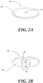
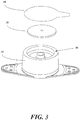
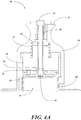


Classifications
-
- A—HUMAN NECESSITIES
- A61—MEDICAL OR VETERINARY SCIENCE; HYGIENE
- A61M—DEVICES FOR INTRODUCING MEDIA INTO, OR ONTO, THE BODY; DEVICES FOR TRANSDUCING BODY MEDIA OR FOR TAKING MEDIA FROM THE BODY; DEVICES FOR PRODUCING OR ENDING SLEEP OR STUPOR
- A61M37/00—Other apparatus for introducing media into the body; Percutany, i.e. introducing medicines into the body by diffusion through the skin
- A61M37/0015—Other apparatus for introducing media into the body; Percutany, i.e. introducing medicines into the body by diffusion through the skin by using microneedles
-
- A—HUMAN NECESSITIES
- A61—MEDICAL OR VETERINARY SCIENCE; HYGIENE
- A61B—DIAGNOSIS; SURGERY; IDENTIFICATION
- A61B17/00—Surgical instruments, devices or methods, e.g. tourniquets
- A61B17/20—Surgical instruments, devices or methods, e.g. tourniquets for vaccinating or cleaning the skin previous to the vaccination
- A61B17/205—Vaccinating by means of needles or other puncturing devices
-
- A—HUMAN NECESSITIES
- A61—MEDICAL OR VETERINARY SCIENCE; HYGIENE
- A61B—DIAGNOSIS; SURGERY; IDENTIFICATION
- A61B50/00—Containers, covers, furniture or holders specially adapted for surgical or diagnostic appliances or instruments, e.g. sterile covers
- A61B50/30—Containers specially adapted for packaging, protecting, dispensing, collecting or disposing of surgical or diagnostic appliances or instruments
-
- A—HUMAN NECESSITIES
- A61—MEDICAL OR VETERINARY SCIENCE; HYGIENE
- A61M—DEVICES FOR INTRODUCING MEDIA INTO, OR ONTO, THE BODY; DEVICES FOR TRANSDUCING BODY MEDIA OR FOR TAKING MEDIA FROM THE BODY; DEVICES FOR PRODUCING OR ENDING SLEEP OR STUPOR
- A61M37/00—Other apparatus for introducing media into the body; Percutany, i.e. introducing medicines into the body by diffusion through the skin
- A61M37/0015—Other apparatus for introducing media into the body; Percutany, i.e. introducing medicines into the body by diffusion through the skin by using microneedles
- A61M2037/0023—Drug applicators using microneedles
-
- A—HUMAN NECESSITIES
- A61—MEDICAL OR VETERINARY SCIENCE; HYGIENE
- A61M—DEVICES FOR INTRODUCING MEDIA INTO, OR ONTO, THE BODY; DEVICES FOR TRANSDUCING BODY MEDIA OR FOR TAKING MEDIA FROM THE BODY; DEVICES FOR PRODUCING OR ENDING SLEEP OR STUPOR
- A61M2209/00—Ancillary equipment
- A61M2209/06—Packaging for specific medical equipment
Definitions
- the present invention relates to a system suitable for protecting a microneedle patch and applying the microneedle patch to a skin surface, and more particularly to a system enabling storage of a microneedle patch in a sterile packaging and transfer and deployment of the patch to a skin surface for delivery of an agent.
- Microneedle patch technology enables drug delivery into the epidermal and/or dermal layers of the skin.
- the technology is capable of delivering drugs of different types, size, structure, or charge.
- Microneedle patches can be applied to patients regardless of their skin characteristics. The patches are optimized to penetrate the shallow layers of the skin, avoiding pain receptors, and to deliver their drug payloads.
- microneedle patches can be difficult.
- the patches can be very small and thus challenging for a patient to handle without damaging and/or contaminating the microneedles prior to application to the skin.
- microneedle patches must be applied to the skin with a sufficient impact to ensure that the microneedles penetrate the skin to a required degree for the intended drug delivery to occur. This presents additional challenges to patients using the patches, particularly in self-delivery situations.
- WO2005/044333 A2 describes an applicator for applying a microprojection member to the stratum corneum of a patient having a housing, a piston moveable within the housing and a cap adapted to activate the applicator.
- a device as claimed is neither described nor suggested in this document.
- US 6 855 131 B2 is concerned with a retainer for holding a microprotrusion member for application of the microprotrusion member to the stratum corneum with an impact applicator.
- the microprotrusion member includes a plurality of microprotrusions which penetrate the stratum corneum to improve transport of an agent across the stratum corneum.
- a device as claimed is neither described nor suggested in this document.
- WO2006/108185 A1 discloses a microneedle application device for moving a microneedle array toward a target skin location includes a feedback sensor.
- the feedback sensor is operably connected to the microneedle application device, and is capable of generating an output corresponding to forces between the target skin location and the microneedle application device.
- WO2007/002521 A2 describes an applicator device including a housing, an impactor for impacting a microneedle array and accelerating the microneedle array toward the target site, wherein the impactor is capable of moving along an arcuate path to move the microneedle array toward the target site.
- an applicator device including a housing, a patch applicator pivotally supported by the housing, and a torsion spring.
- the patch applicator has a retaining portion and a patch contacting portion, and the patch contacting portion is capable of moving along a substantially arcuate path between a first position and a second position.
- the torsion spring is capable of biasing the patch applicator relative to the housing.
- microneedle patch applicator system that can reduce or eliminate the potential for damage and/or contamination of the microneedle patch due to handling by a patient or user, while also ensuring the application of the microneedle patch to the skin surface is effected in accordance with the design parameters for skin penetration and drug delivery, and in a consistently repeatable manner.
- the present invention is directed toward further solutions to address this need, in addition to having other desirable characteristics.
- microneedle patch applicator system comprising:
- a microneedle patch applicator includes a housing.
- a slidably disposed applicator plate moveable between a retracted position and a deployed position in a reciprocating manner, includes an engaging surface.
- a compression spring can mount in such a way that imparts a spring force to the applicator plate when the applicator plate is in the retracted position.
- a microneedle patch docking mechanism can be configured in such a way that the docking mechanism captures and holds a microneedle patch in a position proximal the engaging surface of the applicator plate while the applicator plate is in the retracted position.
- a latch mechanism can be included that when latched holds the applicator plate in place and when unlatched permits the applicator plate to move.
- the applicator plate can be placed in the retracted position with the docking mechanism holding the microneedle patch proximal the engaging surface, and when the latch mechanism is unlatched, the applicator plate can be propelled by the compression spring to the deployed position.
- a trigger mechanism can be included, configured in such in such a way that activation of the trigger unlatches the latch mechanism.
- the latch mechanism can be in an unlatched position, enabling the applicator plate to be capable of retraction to the retracted position in response to a force applied to the microneedle patch applicator. Unlatching of the latch mechanism when the applicator plate is in the retracted position can release the applicator plate enabling movement from the retracted position to the deployed position with a kinetic energy of between about 0,0113 N ⁇ m and about 1,13 N ⁇ m, and preferably between about 0,113 N ⁇ m and about 0,266 N ⁇ m.
- the compression, spring can have a spring constant of between about 0,0113 N-m and about 5,65 N-m and preferably between 0,2712 and about 0,9605 N ⁇ m.
- the microneedle patch applicator can deploy the microneedle patch with sufficient force to anchor the microneedle patch to a skin surface with a plurality of microneedles disposed thereon.
- the microneedle patch applicator can be stored in a sterile packaging prior to use.
- a microneedle patch support can include a housing having a perimeter defining an internal area.
- An elevated hub can be disposed within the internal area.
- the microneedle patch support can be sized and dimensioned to support a microneedle patch in such a way that the microneedle patch rests on the elevated hub, and any needles extending from the microneedle patch do not make contact with the microneedle patch support.
- the perimeter defining the internal area can be substantially circular in shape.
- the elevated hub can be disposed at a location that is substantially at a center point of the internal area.
- the elevated hub can include a substantially mesa shape with a hollow center at a substantially flat portion of a top of the elevated hub.
- the elevated hub can have a hollow center.
- a microneedle patch applicator system includes an applicator having a housing.
- a slidably disposed applicator plate moveable between a retracted position and a deployed position in a reciprocating manner, can have an engaging surface.
- a compression spring can be mounted in such a way that imparts a spring force to the applicator plate when the applicator plate is in the retracted position.
- a microneedle patch docking mechanism can be configured in such a way that the docking mechanism captures and holds a microneedle patch in a position proximal the engaging surface of the applicator plate while the applicator plate is in the retracted position.
- a latch mechanism can be provided that when latched holds the applicator plate in place and when unlatched permits the applicator plate to move.
- the microneedle patch can be disposed on a support. Upon placement of the applicator onto the microneedle patch and the support, application of force to the applicator can cause retraction of the applicator plate to the retracted position and capture of the microneedle patch by the docking mechanism.
- a trigger mechanism can be configured in such in such a way that activation of the trigger unlatches the latch mechanism.
- the applicator plate can be capable of retraction to the retracted position in response to a force applied to the applicator. Unlatching of the latch mechanism when the applicator plate is in the retracted position can release the applicator plate enabling movement from the retracted position to the deployed position with a kinetic energy of between about 0,0113 N ⁇ m and about 1,13 N ⁇ m, and preferably between about 0,113 N-m and about 0,266 N ⁇ m.
- the applicator can deploy the microneedle patch with sufficient force to anchor the microneedle patch to a skin surface with a plurality of microneedles disposed thereon.
- the microneedle patch can include a plurality of microneedles configured for anchoring the microneedle patch to a skin surface.
- the microneedle patch can include a plurality of microneedles configured to contain and deliver a bioactive agent upon attaching to a skin surface.
- the microneedle patch can be stored in a sterile packaging prior to use in the applicator.
- the microneedle patch can be stored together with the support in a sterile packaging prior to use of the microneedle patch in the applicator.
- the microneedle patch can contain one or more bioactive agents disposed thereon.
- the support can include a perimeter defining an internal area.
- An elevated hub can be disposed at a location that is substantially at a center point of the internal area.
- the elevated hub can include a substantially mesa shape with a hollow center at a substantially flat portion of a top of the elevated hub.
- the elevated hub can have a hollow center.
- An illustrative embodiment of the present invention relates to a microneedle patch applicator system.
- the system includes an applicator.
- the applicator includes a housing, a slidably disposed applicator plate, and a compression spring.
- the applicator plate is moveable (e.g., slidable) between a retracted position and a deployed position, and has an engaging surface suitable for mashing up against a microneedle patch and impacting it against a skin surface.
- the compression spring mounts within the applicator in such a way that the spring imparts a spring force to the applicator plate when the applicator plate is in the retracted position.
- the applicator further includes a microneedle patch docking mechanism configured to capture a microneedle patch, and a latch mechanism that when latched holds the applicator plate in place.
- the microneedle patch applicator system further includes a microneedle patch disposed on a support. Upon placement of the applicator onto the microneedle patch and support, application of force to the applicator causes retraction of the applicator plate to the retracted position and capture of the microneedle patch by the docking mechanism. At this juncture, the applicator is then placed on a skin surface of a patient and the latch mechanism is unlatched, releasing the spring force to move the applicator plate and the microneedle patch rapidly against the skin surface.
- microneedles of the microneedle patch Upon impact of the applicator plate and the microneedle patch against the skin surface, microneedles of the microneedle patch are driven into the skin surface, anchoring the microneedle patch to the skin surface and initiating the agent delivery.
- the compression spring may continue to impart a spring force against the applicator plate while in the deployed position to hold the microneedle patch against the skin surface.
- FIGS. 1 through 5 illustrate an example embodiment of a microneedle patch applicator system according to the present invention.
- FIGS. 1 through 5 illustrate an example embodiment of a microneedle patch applicator system according to the present invention.
- the system 10 generally includes an applicator 12 and a microneedle patch support 14.
- the applicator 12 includes a housing 16.
- the housing 16 provides the structure that supports the components required for the applicator 12.
- the housing 16 can form an internal chamber 22 in accordance with some embodiments of the present invention. However, an internal chamber 22 is not necessarily required.
- One function of the internal chamber 22 can be to serve as a guide for the moving components of the applicator 12, as would be understood by one of skill in the art given the present description.
- the housing 16 can be formed of a number of different materials, including but not limited to metal, rubber, wood, plastic, composite, synthetic or natural materials, and the like, such that sufficient structural support is provided for the intended use of the applicator 12.
- the housing 16 may include a splaying mechanism or feature (not shown) capable of causing the skin of a patient to stretch when the applicator 12 is pressed against the skin, making the skin more receptive of the microneedle patch 38 as delivered by the system 10 of the preset invention.
- a splaying mechanism or feature capable of causing the skin of a patient to stretch when the applicator 12 is pressed against the skin, making the skin more receptive of the microneedle patch 38 as delivered by the system 10 of the preset invention.
- a slidably disposed applicator plate 18 can be provided, able to move in a reciprocating manner relative to the housing 16.
- the applicator plate 18 includes an engaging surface 20, and can take a number of different structural forms.
- the engaging surface 20 is utilized to engage a microneedle patch as described herein. As shown, the engaging surface 20 is a substantially solid planar surface. However, there is no requirement that the engaging surface 20 have this example structure.
- the microneedle patch 38 as described later herein has one or more needles extending from its surface.
- the engaging surface 20 need only exist in locations so as to be able to mash up against the back of each microneedle to drive it into the patient's skin as described later herein.
- the continuous planar surface of the illustrative example reduces the likelihood that a misaligned microneedle patch would not receive the appropriate force at the appropriate location to drive the microneedle as required, but such a continuous planar surface is merely a preferred embodiment, as would be understood by those of skill in the art.
- the applicator plate 18, as shown, takes the form of a plunger, capable of sliding movement in a reciprocating manner within the internal chamber 22 of the housing 16.
- the walls of the internal chamber 22 serve to guide the applicator plate 18 in its reciprocating movement within the housing 16.
- the applicator plate 18 can be formed of a number of different materials, including but not limited to metal, rubber, wood, plastic, composite, synthetic or natural materials, and the like, such that the applicator plate 18 can operate as intended and described herein.
- the slidably disposed applicator plate 18 is moveable between a retracted position and a deployed position. As shown in FIG. 1 , the applicator plate 18 is in a deployed position, demonstrated by the applicator plate 18 being located at a bottom perimeter edge of the housing 16, such that the applicator plate 18 can make contact with a skin surface, or other surface, if the applicator 12 were placed up against such a surface.
- FIG. 4B shows the applicator plate 18 in a fully retracted position, as will be described later herein.
- the applicator plate 18 can extend slightly beyond the perimeter edge of the housing 16, such that contact with a skin surface of a patient is not hindered by concomitant contact with the perimeter edge of the housing 16.
- a compression spring 24 is disposed in the applicator 12, mounted in such a way so as to impart a spring force to the applicator plate 18 when the applicator plate 18 is in the retracted position, as described herein.
- the function of the compression spring 24 is to generate a spring force sufficient to propel the applicator plate 18 from a retracted position (as shown in FIG. 4B ) to a deployed position (as shown in FIG. 1 , and FIG.
- an impact force generated by the slidably disposed applicator plate 18 impacting a skin surface at its deployed position is sufficient to drive a microneedle patch into the skin surface, as described herein.
- varying types of springs, spring dimensions, spring characteristics, spring materials, and the like can be utilized in conjunction with the applicator plate 18 configuration and characteristics to arrive at a desired impact force.
- different mechanical force translators can be utilized to convey the spring force to the applicator plate 18.
- other force generating mechanisms such as levers, and direct application of force by a user, can be used in conjunction with or as an alternative to the compression spring 24, so long as the functionality of the present invention is maintained.
- An illustrative example spring suitable for the present application is a spring having a spring constant (k) of about 0,1921 N ⁇ m.
- springs having a spring constant (k) of 0,2712 N ⁇ m provided an insufficient spring force when utilized with one embodiment of the applicator 12 of the present invention to sufficiently drive the microneedle patch into the skin of a patient. This may have been due to an insufficient compression of the spring.
- a spring having a spring constant (k) of 0,9944 N ⁇ m provided excessive force, such that the resulting impact on the skin of a patient approached an uncomfortable response.
- a spring having a spring constant (k) of between 1,0283 and 5,65 N ⁇ m, and including a more likely range of between 0,2712 N ⁇ m and 0,9605 N ⁇ m results in a device having a generally sufficient impact force while not resulting in undue pain or discomfort to the patient.
- these values can change based on various factors specific to intended applications (e.g., age of patient, whether the patient is an animal or a human, etc.) and can be optimized accordingly, as would be appreciated by one of skill in the art.
- the compression spring 24 working in conjunction with the applicator plate 18 should create a stored kinetic energy of about 0,0113 to 1,13 N ⁇ m, with a preferred range of 0,113 to 0,226 N ⁇ m, when in the retracted position, and further should result in an amount of energy dissipated during implementation of the applicator 12 from a retracted position to a deployed position being between about 0,113 to 0,226 N ⁇ m.
- the applicator 12 can further include a latch mechanism 26 or assembly configured to latch or lock the applicator plate 18 in place, preventing sliding movement when such movement is not desired.
- the latch mechanism 26, in the illustrative embodiment, is formed of a detent 28 able to move between two positions along a stepped indentation 30 of a trigger column 34. As shown in FIG. 1 , the detent 28 takes the form of an o-ring that is positioned in a fully receded step of the stepped indentation 30. In this position, the detent 28 does not apply a substantial pressure against an internal wall 32 of a cylindrical aperture that passes through the applicator plate 18 and that contains the latch mechanism 26.
- the applicator plate 18 is able to move in a reciprocating manner up into the housing 16 and then return to the deployed position.
- This position of the detent 28 as depicted in FIG. 1 occurs when the trigger column 34 is fully depressed by a user.
- FIG. 4A shows the applicator plate 18 in a fully retracted position, and also shows the trigger column 34 in a raised position.
- a trigger spring 36 is configured in such a way that when the trigger column 34 is depressed, a spring force is generated. When the trigger column 34 is released by a user, the spring force of the trigger spring 36 pushes the trigger column 34 upward relative to the applicator plate 18.
- the detent 28 slides along the stepped indentation 30 to a less receded step. This action forces the detent 28 radially outward, applying substantial pressure or force to the internal wall 32 of the applicator plate 18 and to the trigger column 34. While in this position, the detent 28 generates sufficient frictional force to prevent the applicator plate 18 from sliding movement, thus locking the applicator plate 18 into place. As shown in FIG. 4A , the applicator plate 18 is in its fully retracted position. The spring force generated by the compression spring 24 is insufficient to overcome the frictional force of the latch mechanism 26 as generated by the detent 28 as positioned in the stepped indentation 30. As such, the applicator plate 18 is locked in place.
- FIGS. 2A and 2B An example microneedle patch 38 suitable for use with the applicator system 10 of the present invention is shown in FIGS. 2A and 2B from a top perspective view and a bottom perspective view, respectively.
- the microneedle patch 38 includes a substrate 40 configured in a generally circular (e.g., relatively short cylindrical) shape.
- the substrate 40 can have any number of shapes, as would be understood by those of skill in the art, so long as they are compatible with the corresponding applicator 12.
- the substrate 40 includes an aperture 42 passing therethrough, substantially at a center point of the substrate 40.
- the microneedle patch 38 further includes a microneedle array 44 having a plurality of microneedles coupled with the substrate 40.
- the microneedle array 44 can contain an agent therein for delivery to the skin of a patient upon the microneedle array 44 penetrating a skin surface 50 of a patient.
- agent refers to a single agent or a combination of several agents.
- the agent may be biologically active or biologically inactive.
- Sample agents include, without limitation, drugs, vaccines, allergens, antigens, excipients, anti-coagulants, surfactants, radiological dyes or markers, toxins, or any other agent, compound or substance suitable for introduction into a biological environment.
- the agent may be, for example, dry (e.g., a film), or in a semi-solid gel.
- dry e.g., a film
- semi-solid gel e.g.
- a docking mechanism 46 is configured to capture a microneedle patch 38, as shown in FIG. 1 ( see also , FIGS. 4A-4C ).
- the docking mechanism 46 takes the form of an end section of the trigger column 34.
- the end section of the trigger column 34 is sized and dimensioned to form an interference fit with the aperture 42 of the microneedle patch 38.
- the docking mechanism 46 when placed through the aperture 42 of the microneedle patch 38 frictionally couples with the aperture 42, thus docking or loading the microneedle patch 38 onto the applicator 12.
- One feature of this docking configuration is that the microneedle patch 38 is docked with the applicator 12 in a removable manner.
- the microneedle patch 38 will pull away from the docking mechanism 46 of the applicator 12 relatively easily.
- One of skill in the art will appreciate that a number of alternative docking mechanisms may be utilized to dock or load the microneedle patch 38 onto the applicator 12, such that the present invention is by no means limited to the specific mechanical embodiment described herein. Rather, it is anticipated that other docking mechanisms may be utilized with the applicator 12 of the present invention to provide a removable coupling of the microneedle patch 38 with the applicator 12 in a desired manner. All such equivalent docking mechanisms are anticipated for use with the present invention.
- the microneedle patch applicator system 10 further includes a microneedle patch support 14.
- the microneedle patch support 14 is essentially a base structure capable of supporting the microneedle patch 38 in such a way that the microneedle array 44 is protected from inadvertent contact during storage or handling.
- the microneedle patch support 14 holds the microneedle patch 38 with the microneedle array 44 on an inside facing surface of the microneedle patch 38 (i.e., the surface facing the microneedle patch support 14).
- the microneedle patch 38 rests on an elevated hub 52, or boss, in an internal area 54 formed by a perimeter 56 edge of the support 14 ( see also FIG. 3 ).
- the elevated hub 52 has a mesa shape, meaning essentially a substantially flat top with steep sides, not necessarily vertical, though vertical sides can be implemented.
- the substantially flat top provides a surface to engage with the microneedle patch 38 near a center of the patch, and the steep drop-off of the sides removes the likelihood of any of the support structure interfering with the microneedles of the microneedle array 44.
- This example configuration directs the microneedles of the microneedle array 44 inward, and suspends the microneedles within the internal area 54, such that they are hidden from a user and not exposed to the environment outside of the microneedle patch support 14.
- a sealing cover 58 can be placed across the support 14 from edge to edge of the perimeter 56, and across the microneedle patch 38, such that the sealing cover 58 applies downward pressure on the microneedle patch 38, holding it against the elevated hub 52, and internal walls of the support along the perimeter 56 prevent the microneedle patch 38 from sliding laterally relative to the elevated hub 52, thus holding the microneedle patch 38 in place and in a sealed configuration.
- the sealing cover 58 can be applied with clearance between the sealing cover 58 and the microneedle patch 38, such that the patch is held substantially in place between the elevated hub 52 (e.g., boss), the sealing cover 58 (e.g., lid), and the perimeter 56.
- the sealing cover 58 can be adhered to the support 14 using a chemical adhesive, a heat seal, or the like. Such an arrangement lends itself to the maintenance of a sterile environment within which the microneedle patch 38 can be stored until use.
- the microneedle patch support 14 further provides sufficient support to hold the microneedle patch 38 in place when the applicator 12 is placed over the microneedle patch support 14 and the support 14 is used to apply a force to the applicator plate 18 and push it into a retracted position. As such, the support 14 must be able to withstand at least a force equivalent to the maximum spring force generated by the compression spring 24 during such a process of retracting the applicator plate 18.
- the microneedle patch support 14 may be made of a generally rigid material, including but not limited to, wood, plastic, composite, metal, and the like. A preferred implementation is to form the support 14 of plastic.
- the microneedle patch applicator system 10 of the present invention can be utilized as follows. With the microneedle patch 38 resting on the microneedle patch support 14, the applicator 12 is placed over the support 14 (as shown in FIG. 1 ) (step 100). The trigger button 35 is depressed (step 102), unlatching the latch mechanism 26 and enabling the sliding movement of the applicator plate 18. The applicator 12 is lowered onto the support 14 until the applicator plate 18 makes contact with the perimeter 56 of the support 14 (step 104). Such action presses the engaging surface 20 of the applicator plate 18 against the support 14 at the perimeter 56 of the support 14.
- a downward force applied to the applicator 12 overcomes the spring force of the compression spring 24 and lowers the applicator housing 16, retracting the applicator plate 18.
- the docking mechanism 46 engages with the microneedle patch 38 at the aperture 42, in accordance with the example illustrative embodiment.
- the microneedle patch 38 is docked with the applicator 12 (step 106).
- the trigger button 35 is released and the latch mechanism 26 latches or locks the applicator plate 18 in position (step 108). This is also illustrated in FIG . 4B .
- the applicator 12 can be lifted off the microneedle patch support 14 (step 110). Because the microneedle patch 38 is docked to the applicator 12, the microneedle patch 38 pulls off of the patch support 14 and stays coupled with the applicator 12 at the docking mechanism 46.
- the applicator 12 is then repositioned against a skin surface 50 of a patient (step 112), and the trigger button 35 is depressed to deploy the applicator plate 18 and the microneedle patch 38 (step 114), as shown in FIG. 4C . More specifically, this action unlatches the latch mechanism 26, again allowing sliding movement of the applicator plate 18. With the stored energy of the compression spring 24, the applicator plate 18 is thrust outward (or downward, as illustrated in FIG. 4C ) and impacts the skin surface 50 with the microneedle patch 38. The impact force drives the microneedle patch 38, and specifically the microneedle array 44, into the skin surface 50 anchoring the microneedle patch 38 to the skin surface 50 via the adhesive of the microneedle patch 38.
- the applicator 12 can then be removed from the skin surface 50 (step 116), leaving the microneedle patch 38 anchored/adhered to the skin surface 50.
- the applicator 12 is then available for future use, repeating the process as described herein, for the application of additional microneedle patches. Accordingly, the applicator 12 of the present invention is reusable. In accordance with one example implementation of the present invention, the applicator 12 can be reused between 30 and 50 times, or more. Each instance of use does require a new microneedle patch to be docked in the applicator 12 and then deployed to the skin surface 50 of a patient.
- microneedle patch 38 and the microneedles of the microneedle array 44 are sterile.
- various processes can be utilized to sterilize the microneedle patch 38 and the microneedle array 44, including but not limited to heat, light, or chemical sterilization processes, including but not limited to heat sterilization, steam sterilization, gamma sterilization, e-beam sterilization, Ethylene Oxide (EtO) sterilization, and the like.
- microneedle patch 38 can be sterilized, together with the microneedle patch support 14, and both components placed and sealed in sterile packaging for storage, or the components can be separately sterilized before being sealed in packaging for shipment or storage.
- the microneedle patch 38 coupled with the support 14 can be removed from the sterile packaging by a user, without need for the user to directly handle the microneedle patch 38.
- the user can handle only the support 14, thus maintaining the sterility of the microneedle patch 38 and the microneedle array 44.
- the microneedle patch 38 is then docked to the applicator 12 as described herein, and deployed to the skin surface 50 of a patient, all without anything contacting the microneedles until they impact the skin surface 50.
- a package or packages suitable for protecting a drug-loaded microneedle patch, as well as the applicator 12, can be provided to maintain the microneedle patch 38 in a sterile condition prior to use.
- Suitable packaging protects the microneedle patch 38 from physical/mechanical harm, as well as environment conditions (e.g., moisture, oxygen, other volatiles, etc.), and be a sterile barrier (primary package).
- Example materials include plastic based materials, including plastic composites and plastic films, metalized plastic films, foil based materials, paper based materials, or synthetic non-woven materials (e.g., flashspun high-density polyethylene fibers) optionally with adhesive (e.g., pressure sensitive adhesive or hot melt adhesive) that in combination provide an airtight an air tight sterile barrier.
- adhesive e.g., pressure sensitive adhesive or hot melt adhesive
- agent disposed on the microneedle patch has been defined broadly herein. More specific illustrative examples of such agent include, but are not limited to, therapeutic agents in all the major therapeutic areas including, but not limited to, anti-infectives, such as antibiotics and antiviral agents; analgesics, including fentanyl, sufentanil, remifentanil, buprenorphine and analgesic combinations; anesthetics; anorexics; antiarthritics; antiasthmatic agents such as terbutaline; anticonvulsants; antidepressants; antidiabetic agents; antidiarrheals; antihistamines; anti-inflammatory agents; antimigraine preparations; antimotion sickness preparations such as scopolamine and ondansetron; antinauseants; antineoplastics; antiparkinsonism drugs; antipruritics; antipsychotics; antipyretics; antispasmodics, including gastrointestinal and urinary; anticholinergic
- agents may take the form of peptides, proteins, carbohydrates (including monosaccharides, oligosaccharides, and polysaccharides), nucleoproteins, mucoproteins, lipoproteins, glycoproteins, nucleic acid molecules (including any form of DNA such as cDNA, RNA, or a fragment thereof, oligonucleotides, and genes), nucleotides, nucleosides, lipids, biologically active organic or inorganic molecules, or combinations thereof.
- carbohydrates including monosaccharides, oligosaccharides, and polysaccharides
- nucleoproteins mucoproteins
- lipoproteins glycoproteins
- nucleic acid molecules including any form of DNA such as cDNA, RNA, or a fragment thereof, oligonucleotides, and genes
- nucleotides nucleosides, lipids, biologically active organic or inorganic molecules, or combinations thereof.
- agents include, without limitation, growth hormone release hormone (GHRH), growth hormone release factor (GHRF), insulin, insultropin, calcitonin, octreotide, endorphin, TRN, NT-36 (chemical name: N-[[(s)-4-oxo-2-azetidinyl]carbonyl]-L-histidyl-L-p-rolinamide), liprecin, pituitary hormones (e.g., HGH, HMG, desmopressin acetate, etc), follicle luteoids, aANF, growth factors such as growth factor releasing factor (GFRF), bMSH, GH, somatostatin, bradykinin, somatotropin, platelet-derived growth factor releasing factor, asparaginase, bleomycin sulfate, chymopapain, cholecystokinin, chorionic gonadotropin, erythropoietin,
- the agent can be in various forms, including free bases, acids, charged or uncharged molecules, components of molecular complexes or nonirritating, pharmacologically acceptable salts. Further, simple derivatives of the agent (such as ethers, esters, amides, etc.), which are easily hydrolyzed at body pH, enzymes, etc., can be employed.
- the agent may include a viscosity enhancing agent, such as maleic acid, malic acid, malonic acid, tartaric acid, adipic acid, citraconic acid, fumaric acid, glutaric acid, itaconic acid, meglutol, mesaconic acid, succinic acid, citramalic acid, tartronic acid, citric acid, tricarballylic acid, ethylenediarninetetraacetic acid, aspartic acid, glutamic acid, carbonic acid, sulfuric acid, phosphoric acid, hydrochloric acid, hydrobromic acid, nitric acid, sulfuric acid, benzene sulfonic acid, methane sulfonic acid, glycolic acid, gluconic acid, glucuronic acid, lactic acid, pyruvic acid, tartronic acid, propionic acid, pentanoic acid, carbonic acid, adipic acid, citraconic acid, and levulinic acid.
- a viscosity enhancing agent such as male
- Additional potential agents include surfactants, such as zwitterionic, amphoteric, cationic, anionic, or nonionic, including, without limitation, sodium lauroamphoacetate, sodium dodecyl sulfate (SDS), cetylpyridinium chloride (CPC), dodecyltrimethyl ammonium chloride (TMAC), benzalkonium, chloride, polysorbates such as Tween 20 and Tween 80, other sorbitan derivatives, such as sorbitan laurate, and alkoxylated alcohols, such as laureth-4.
- surfactants such as zwitterionic, amphoteric, cationic, anionic, or nonionic, including, without limitation, sodium lauroamphoacetate, sodium dodecyl sulfate (SDS), cetylpyridinium chloride (CPC), dodecyltrimethyl ammonium chloride (TMAC), benzalkonium, chloride, polysorbates such as Tween
- Still other useful agents include include polymeric materials or polymers that have amphiphilic properties, for example and without, cellulose derivatives, such as hydroxyethylcellulose (HEC), hydroxypropylmethylcell--ulose (HPMC), hydroxypropycellulose (HPC), methylcellulose (MC), hydroxyethylmethylcellulose (HEMC), or ethylhydrox-ethylcellulose (EHEC), as well as pluronics.
- HEC hydroxyethylcellulose
- HPMC hydroxypropylmethylcell--ulose
- HPMC hydroxypropycellulose
- HPC hydroxypropycellulose
- MC methylcellulose
- HEMC hydroxyethylmethylcellulose
- EHEC ethylhydrox-ethylcellulose
- biocompatible carriers include, without limitation, human albumin, bioengineered human albumin, polyglutamic acid, polyaspartic acid, polyhistidine, pentosan polysulfate, polyamino acids, sucrose, trehalose, melezitose, raffinose and stachyose.
- Agents can further include stabilizing agents, which can comprise, without limitation, a non-reducing sugar, a polysaccharide or a reducing sugar.
- Suitable non-reducing sugars include, for example, sucrose, trehalose, stachyose, or raffinose.
- Suitable polysaccharides include, for example, dextran, soluble starch, dextrin, and insulin.
- Suitable reducing sugars include, for example, monosaccharides such as, for example, apiose, arabinose, lyxose, ribose, xylose, digitoxose, fucose, quercitol, quinovose, rhamnose, allose, altrose, fructose, galactose, glucose, gulose, hamamelose, idose, mannose, tagatose, and the like; and disaccharides such as, for example, primeverose, vicianose, rutinose, scillabiose, cellobiose, gentiobiose, lactose, lactulose, maltose, melibiose, sophorose, and turanose, and the like.
- monosaccharides such as, for example, apiose, arabinose, lyxose, ribose, xylose, digitox
- pathway patency modulators can comprise, without limitation, osmotic agents 202 (e.g., sodium chloride), zwitterionic compounds (e.g., amino acids), and anti-inflammatory agents, such as betamethasone 21-phosphate disodium salt, triamcinolone acetonide 21-disodium phosphate, hydrocortamate hydrochloride, hydrocortisone 21-phosphate disodium salt, methylprednisolone 21-phosphate disodium salt, methylprednisolone 21-succinaate sodium salt, paramethasone disodium phosphate and prednisolone 21-succinate sodium salt, and anticoagulants, such as citric acid, citrate salts (e.g., sodium citrate), dextrin sulfate sodium, aspirin and EDTA.
- osmotic agents 202 e.g., sodium chloride
- zwitterionic compounds e.g., amino acids
- Further agents include a solubilising/complexing agent, for example, alpha-cyclodextrin, beta-cyclodextrin, gamma-cyclodextrin, glucosyl-alpha-cyclodextrin, maltosyl-alpha-cyclodextrin, glucosyl-beta-cyclodextrin, maltosyl-beta-cyclodextrin, hydroxypropyl beta-cyclodextrin, 2-hydroxypropyl-beta-cyclodextrin, 2-hydroxypropyl-gamma-cyclodextrin, hydroxyethyl-beta-cyclodextrin, methyl-beta-cyclodextrin, sulfobutylether-alpha-cyclodextrin, sulfobutylether-beta-cyclodextrin, sulfobutylether7 beta-cyclodextrin, and
- Additional useful agents include non-aqueous solvents, such as ethanol, isopropanol, methanol, propanol, butanol, propylene glycol, dimethysulfoxide, glycerin, N,N-dimethylformamide and polyethylene glycol 400.
- non-aqueous solvents such as ethanol, isopropanol, methanol, propanol, butanol, propylene glycol, dimethysulfoxide, glycerin, N,N-dimethylformamide and polyethylene glycol 400.
Description
- The present invention relates to a system suitable for protecting a microneedle patch and applying the microneedle patch to a skin surface, and more particularly to a system enabling storage of a microneedle patch in a sterile packaging and transfer and deployment of the patch to a skin surface for delivery of an agent.
- Microneedle patch technology enables drug delivery into the epidermal and/or dermal layers of the skin. The technology is capable of delivering drugs of different types, size, structure, or charge. Microneedle patches can be applied to patients regardless of their skin characteristics. The patches are optimized to penetrate the shallow layers of the skin, avoiding pain receptors, and to deliver their drug payloads.
- Application of microneedle patches can be difficult. The patches can be very small and thus challenging for a patient to handle without damaging and/or contaminating the microneedles prior to application to the skin. Furthermore, microneedle patches must be applied to the skin with a sufficient impact to ensure that the microneedles penetrate the skin to a required degree for the intended drug delivery to occur. This presents additional challenges to patients using the patches, particularly in self-delivery situations.
WO2005/044333 A2 describes an applicator for applying a microprojection member to the stratum corneum of a patient having a housing, a piston moveable within the housing and a cap adapted to activate the applicator. A device as claimed is neither described nor suggested in this document.
US 6 855 131 B2 is concerned with a retainer for holding a microprotrusion member for application of the microprotrusion member to the stratum corneum with an impact applicator. The microprotrusion member includes a plurality of microprotrusions which penetrate the stratum corneum to improve transport of an agent across the stratum corneum. A device as claimed is neither described nor suggested in this document.
WO2006/108185 A1 discloses a microneedle application device for moving a microneedle array toward a target skin location includes a feedback sensor. The feedback sensor is operably connected to the microneedle application device, and is capable of generating an output corresponding to forces between the target skin location and the microneedle application device. A device as claimed is neither described nor suggested in this document.
WO2007/002521 A2 describes an applicator device including a housing, an impactor for impacting a microneedle array and accelerating the microneedle array toward the target site, wherein the impactor is capable of moving along an arcuate path to move the microneedle array toward the target site. Also, an applicator device including a housing, a patch applicator pivotally supported by the housing, and a torsion spring. The patch applicator has a retaining portion and a patch contacting portion, and the patch contacting portion is capable of moving along a substantially arcuate path between a first position and a second position. The torsion spring is capable of biasing the patch applicator relative to the housing. A device as claimed is neither described nor suggested in this document. - There is a need for a microneedle patch applicator system that can reduce or eliminate the potential for damage and/or contamination of the microneedle patch due to handling by a patient or user, while also ensuring the application of the microneedle patch to the skin surface is effected in accordance with the design parameters for skin penetration and drug delivery, and in a consistently repeatable manner. The present invention is directed toward further solutions to address this need, in addition to having other desirable characteristics.
- In particular the invention is directed to a microneedle patch applicator system, comprising:
- an applicator (12), comprising:
- a housing (16);
- a slidably disposed applicator plate (18), moveable between a retracted position and a deployed position in a reciprocating manner, the applicator plate (18) having an engaging surface (20);
- a compression spring (24) mounted within the applicator (12) and in contact with and applying a spring force to the applicator plate (18) when the applicator plate (18) is in the retracted position;
- a microneedle patch docking mechanism (46) which provides a removable coupling of the microneedle patch (38) with applicator (12) and characterizedd in holding the microneedle patch (38) in a position proximal the engaging surface of the applicator plate (18) while the applicator plate (18) is in the retracted position; and
- a latch mechanism (26) that when latched holds the applicator plate (18) in place and when unlatched permits the applicator plate (18) to move; and
- the microneedle patch (38) disposed on a support (14);
- wherein upon placement of the applicator (12) onto the microneedle patch (38) and the support, application of force to the applicator (12) causes retraction of the applicator plate (18) to the retracted position and capture of the microneedle patch (38) by the docking mechanism (46).
- In accordance with example embodiments of the present invention, a microneedle patch applicator includes a housing. A slidably disposed applicator plate, moveable between a retracted position and a deployed position in a reciprocating manner, includes an engaging surface. A compression spring can mount in such a way that imparts a spring force to the applicator plate when the applicator plate is in the retracted position. A microneedle patch docking mechanism can be configured in such a way that the docking mechanism captures and holds a microneedle patch in a position proximal the engaging surface of the applicator plate while the applicator plate is in the retracted position. A latch mechanism can be included that when latched holds the applicator plate in place and when unlatched permits the applicator plate to move. The applicator plate can be placed in the retracted position with the docking mechanism holding the microneedle patch proximal the engaging surface, and when the latch mechanism is unlatched, the applicator plate can be propelled by the compression spring to the deployed position.
- In accordance with aspects of the present invention, a trigger mechanism can be included, configured in such in such a way that activation of the trigger unlatches the latch mechanism. The latch mechanism can be in an unlatched position, enabling the applicator plate to be capable of retraction to the retracted position in response to a force applied to the microneedle patch applicator. Unlatching of the latch mechanism when the applicator plate is in the retracted position can release the applicator plate enabling movement from the retracted position to the deployed position with a kinetic energy of between about 0,0113 N·m and about 1,13 N·m, and preferably between about 0,113 N·m and about 0,266 N·m.
- In accordance with further aspects of the present invention, the compression, spring can have a spring constant of between about 0,0113 N-m and about 5,65 N-m and preferably between 0,2712 and about 0,9605 N·m. The microneedle patch applicator can deploy the microneedle patch with sufficient force to anchor the microneedle patch to a skin surface with a plurality of microneedles disposed thereon. The microneedle patch applicator can be stored in a sterile packaging prior to use.
- In accordance with example embodiments of the present invention, a microneedle patch support can include a housing having a perimeter defining an internal area. An elevated hub can be disposed within the internal area. The microneedle patch support can be sized and dimensioned to support a microneedle patch in such a way that the microneedle patch rests on the elevated hub, and any needles extending from the microneedle patch do not make contact with the microneedle patch support.
- In accordance with aspects of the present invention, the perimeter defining the internal area can be substantially circular in shape. The elevated hub can be disposed at a location that is substantially at a center point of the internal area. The elevated hub can include a substantially mesa shape with a hollow center at a substantially flat portion of a top of the elevated hub. The elevated hub can have a hollow center.
- In accordance with example embodiments of the present invention, a microneedle patch applicator system includes an applicator having a housing. A slidably disposed applicator plate, moveable between a retracted position and a deployed position in a reciprocating manner, can have an engaging surface. A compression spring can be mounted in such a way that imparts a spring force to the applicator plate when the applicator plate is in the retracted position. A microneedle patch docking mechanism can be configured in such a way that the docking mechanism captures and holds a microneedle patch in a position proximal the engaging surface of the applicator plate while the applicator plate is in the retracted position. A latch mechanism can be provided that when latched holds the applicator plate in place and when unlatched permits the applicator plate to move. The microneedle patch can be disposed on a support. Upon placement of the applicator onto the microneedle patch and the support, application of force to the applicator can cause retraction of the applicator plate to the retracted position and capture of the microneedle patch by the docking mechanism.
- In accordance with aspects of the present invention, a trigger mechanism can be configured in such in such a way that activation of the trigger unlatches the latch mechanism. When the latch mechanism is in an unlatched position, the applicator plate can be capable of retraction to the retracted position in response to a force applied to the applicator. Unlatching of the latch mechanism when the applicator plate is in the retracted position can release the applicator plate enabling movement from the retracted position to the deployed position with a kinetic energy of between about 0,0113 N·m and about 1,13 N·m, and preferably between about 0,113 N-m and about 0,266 N·m.
- In accordance with aspects of the present invention, the applicator can deploy the microneedle patch with sufficient force to anchor the microneedle patch to a skin surface with a plurality of microneedles disposed thereon. The microneedle patch can include a plurality of microneedles configured for anchoring the microneedle patch to a skin surface. The microneedle patch can include a plurality of microneedles configured to contain and deliver a bioactive agent upon attaching to a skin surface. The microneedle patch can be stored in a sterile packaging prior to use in the applicator. The microneedle patch can be stored together with the support in a sterile packaging prior to use of the microneedle patch in the applicator. The microneedle patch can contain one or more bioactive agents disposed thereon. The support can include a perimeter defining an internal area. An elevated hub can be disposed at a location that is substantially at a center point of the internal area. The elevated hub can include a substantially mesa shape with a hollow center at a substantially flat portion of a top of the elevated hub. The elevated hub can have a hollow center.
- These and other characteristics of the present invention will be more fully understood by reference to the following detailed description in conjunction with the attached drawings, in which:
-
FIG. 1 is a cross-sectional view of a microneedle patch applicator system, according to one aspect of the present invention; -
FIG. 2A is a perspective view of a top side of a microneedle patch, according to one aspect of the present invention; -
FIG. 2B is a perspective view of a bottom side of the microneedle patch ofFIG. 2A , according to one aspect of the present invention; -
FIG. 3 is an exploded view of the microneedle patch assembled on a support with a sealing cover, according to one aspect of the present invention; -
FIG. 4A is a cross-sectional view of the microneedle patch applicator system with an applicator plate in a fully retracted position while the microneedle patch is being loaded, according to one aspect of the present invention; -
FIG. 4B is a cross-sectional view of the microneedle patch applicator system with the applicator plate in the fully retracted position and the microneedle patch docked or loaded, according to one aspect of the present invention; -
FIG. 4C is a cross-sectional view of the microneedle patch applicator system with the applicator plate in a deployed position and the microneedle patch positioned for transfer to a skin surface, according to one aspect of the present invention; and -
FIG. 5 is a flowchart illustrating a method of loading the microneedle patch applicator with a microneedle patch and deploying the patch on the skin of a patient, according to one aspect of the present invention. - An illustrative embodiment of the present invention relates to a microneedle patch applicator system. The system includes an applicator. The applicator includes a housing, a slidably disposed applicator plate, and a compression spring. The applicator plate is moveable (e.g., slidable) between a retracted position and a deployed position, and has an engaging surface suitable for mashing up against a microneedle patch and impacting it against a skin surface. The compression spring mounts within the applicator in such a way that the spring imparts a spring force to the applicator plate when the applicator plate is in the retracted position. The applicator further includes a microneedle patch docking mechanism configured to capture a microneedle patch, and a latch mechanism that when latched holds the applicator plate in place. The microneedle patch applicator system further includes a microneedle patch disposed on a support. Upon placement of the applicator onto the microneedle patch and support, application of force to the applicator causes retraction of the applicator plate to the retracted position and capture of the microneedle patch by the docking mechanism. At this juncture, the applicator is then placed on a skin surface of a patient and the latch mechanism is unlatched, releasing the spring force to move the applicator plate and the microneedle patch rapidly against the skin surface. Upon impact of the applicator plate and the microneedle patch against the skin surface, microneedles of the microneedle patch are driven into the skin surface, anchoring the microneedle patch to the skin surface and initiating the agent delivery. The compression spring may continue to impart a spring force against the applicator plate while in the deployed position to hold the microneedle patch against the skin surface.
-
FIGS. 1 through 5 , wherein like parts are designated by like reference numerals throughout, illustrate an example embodiment of a microneedle patch applicator system according to the present invention. Although the present invention will be described with reference to the example embodiment illustrated in the figures, it should be understood that many alternative forms can embody the present invention. One of skill in the art will additionally appreciate different ways to alter the parameters of the embodiment disclosed, such as the size, shape, or type of elements or materials, in a manner still in keeping with the scope of the present invention. - Turning now to
FIG. 1 , a microneedlepatch applicator system 10 is provided in accordance with one example embodiment of the present invention. Thesystem 10 generally includes anapplicator 12 and amicroneedle patch support 14. Theapplicator 12 includes ahousing 16. Thehousing 16 provides the structure that supports the components required for theapplicator 12. Thehousing 16 can form aninternal chamber 22 in accordance with some embodiments of the present invention. However, aninternal chamber 22 is not necessarily required. One function of theinternal chamber 22 can be to serve as a guide for the moving components of theapplicator 12, as would be understood by one of skill in the art given the present description. - The
housing 16 can be formed of a number of different materials, including but not limited to metal, rubber, wood, plastic, composite, synthetic or natural materials, and the like, such that sufficient structural support is provided for the intended use of theapplicator 12. - Furthermore, the
housing 16 may include a splaying mechanism or feature (not shown) capable of causing the skin of a patient to stretch when theapplicator 12 is pressed against the skin, making the skin more receptive of themicroneedle patch 38 as delivered by thesystem 10 of the preset invention. One of skill in the art will appreciate how to implement such a feature. - A slidably disposed
applicator plate 18 can be provided, able to move in a reciprocating manner relative to thehousing 16. Theapplicator plate 18 includes an engagingsurface 20, and can take a number of different structural forms. The engagingsurface 20 is utilized to engage a microneedle patch as described herein. As shown, the engagingsurface 20 is a substantially solid planar surface. However, there is no requirement that the engagingsurface 20 have this example structure. Themicroneedle patch 38 as described later herein has one or more needles extending from its surface. The engagingsurface 20 need only exist in locations so as to be able to mash up against the back of each microneedle to drive it into the patient's skin as described later herein. The continuous planar surface of the illustrative example reduces the likelihood that a misaligned microneedle patch would not receive the appropriate force at the appropriate location to drive the microneedle as required, but such a continuous planar surface is merely a preferred embodiment, as would be understood by those of skill in the art. - The
applicator plate 18, as shown, takes the form of a plunger, capable of sliding movement in a reciprocating manner within theinternal chamber 22 of thehousing 16. In the illustrative embodiment, the walls of theinternal chamber 22 serve to guide theapplicator plate 18 in its reciprocating movement within thehousing 16. - The
applicator plate 18 can be formed of a number of different materials, including but not limited to metal, rubber, wood, plastic, composite, synthetic or natural materials, and the like, such that theapplicator plate 18 can operate as intended and described herein. - The slidably disposed
applicator plate 18 is moveable between a retracted position and a deployed position. As shown inFIG. 1 , theapplicator plate 18 is in a deployed position, demonstrated by theapplicator plate 18 being located at a bottom perimeter edge of thehousing 16, such that theapplicator plate 18 can make contact with a skin surface, or other surface, if theapplicator 12 were placed up against such a surface.FIG. 4B shows theapplicator plate 18 in a fully retracted position, as will be described later herein. In accordance with one example embodiment of the present invention, theapplicator plate 18 can extend slightly beyond the perimeter edge of thehousing 16, such that contact with a skin surface of a patient is not hindered by concomitant contact with the perimeter edge of thehousing 16. - A
compression spring 24 is disposed in theapplicator 12, mounted in such a way so as to impart a spring force to theapplicator plate 18 when theapplicator plate 18 is in the retracted position, as described herein. One of skill in the art will appreciate that there are numerous ways of imparting a mechanical spring force to an object. In the present illustrative device, the function of thecompression spring 24 is to generate a spring force sufficient to propel theapplicator plate 18 from a retracted position (as shown inFIG. 4B ) to a deployed position (as shown inFIG. 1 , andFIG. 4C ) in a manner such that an impact force generated by the slidably disposedapplicator plate 18 impacting a skin surface at its deployed position is sufficient to drive a microneedle patch into the skin surface, as described herein. To achieve such a configuration, varying types of springs, spring dimensions, spring characteristics, spring materials, and the like, can be utilized in conjunction with theapplicator plate 18 configuration and characteristics to arrive at a desired impact force. Furthermore, different mechanical force translators can be utilized to convey the spring force to theapplicator plate 18. Still furthermore, other force generating mechanisms, such as levers, and direct application of force by a user, can be used in conjunction with or as an alternative to thecompression spring 24, so long as the functionality of the present invention is maintained. An illustrative example spring suitable for the present application is a spring having a spring constant (k) of about 0,1921 N·m. In experimental instances of the present invention it was found that springs having a spring constant (k) of 0,2712 N·m provided an insufficient spring force when utilized with one embodiment of theapplicator 12 of the present invention to sufficiently drive the microneedle patch into the skin of a patient. This may have been due to an insufficient compression of the spring. It was further found that a spring having a spring constant (k) of 0,9944 N·m provided excessive force, such that the resulting impact on the skin of a patient approached an uncomfortable response. - One of skill in the art will appreciate that the present invention is by no means limited to using a
compression spring 24 having the specific spring constant (k) provided herein. Rather, one of skill in the art will appreciate that springs having other spring constants (k) may be utilized, so long as they provide a sufficient force with a given spring compression when used with theapplicator 12 to drive the microneedle patch into the skin of a patient without causing unnecessary pain or discomfort to the patient. For example, given the results of the example spring constants (k), one of skill in the art may appreciate that a spring having a spring constant (k) of between 1,0283 and 5,65 N·m, and including a more likely range of between 0,2712 N·m and 0,9605 N·m, results in a device having a generally sufficient impact force while not resulting in undue pain or discomfort to the patient. However, these values can change based on various factors specific to intended applications (e.g., age of patient, whether the patient is an animal or a human, etc.) and can be optimized accordingly, as would be appreciated by one of skill in the art. As the spring constant is merely one variable in determining the overall force generated, one of skill in the art will appreciate that thecompression spring 24 working in conjunction with theapplicator plate 18 should create a stored kinetic energy of about 0,0113 to 1,13 N·m, with a preferred range of 0,113 to 0,226 N·m, when in the retracted position, and further should result in an amount of energy dissipated during implementation of theapplicator 12 from a retracted position to a deployed position being between about 0,113 to 0,226 N·m. - The
applicator 12 can further include alatch mechanism 26 or assembly configured to latch or lock theapplicator plate 18 in place, preventing sliding movement when such movement is not desired. Thelatch mechanism 26, in the illustrative embodiment, is formed of adetent 28 able to move between two positions along a steppedindentation 30 of atrigger column 34. As shown inFIG. 1 , thedetent 28 takes the form of an o-ring that is positioned in a fully receded step of the steppedindentation 30. In this position, thedetent 28 does not apply a substantial pressure against aninternal wall 32 of a cylindrical aperture that passes through theapplicator plate 18 and that contains thelatch mechanism 26. As such, theapplicator plate 18 is able to move in a reciprocating manner up into thehousing 16 and then return to the deployed position. This position of thedetent 28 as depicted inFIG. 1 occurs when thetrigger column 34 is fully depressed by a user.FIG. 4A shows theapplicator plate 18 in a fully retracted position, and also shows thetrigger column 34 in a raised position. Atrigger spring 36 is configured in such a way that when thetrigger column 34 is depressed, a spring force is generated. When thetrigger column 34 is released by a user, the spring force of thetrigger spring 36 pushes thetrigger column 34 upward relative to theapplicator plate 18. When thetrigger column 34 is in a raised position, thedetent 28 slides along the steppedindentation 30 to a less receded step. This action forces thedetent 28 radially outward, applying substantial pressure or force to theinternal wall 32 of theapplicator plate 18 and to thetrigger column 34. While in this position, thedetent 28 generates sufficient frictional force to prevent theapplicator plate 18 from sliding movement, thus locking theapplicator plate 18 into place. As shown inFIG. 4A , theapplicator plate 18 is in its fully retracted position. The spring force generated by thecompression spring 24 is insufficient to overcome the frictional force of thelatch mechanism 26 as generated by thedetent 28 as positioned in the steppedindentation 30. As such, theapplicator plate 18 is locked in place. - An
example microneedle patch 38 suitable for use with theapplicator system 10 of the present invention is shown inFIGS. 2A and 2B from a top perspective view and a bottom perspective view, respectively. Themicroneedle patch 38, as shown, includes asubstrate 40 configured in a generally circular (e.g., relatively short cylindrical) shape. Thesubstrate 40 can have any number of shapes, as would be understood by those of skill in the art, so long as they are compatible with the correspondingapplicator 12. Thesubstrate 40 includes anaperture 42 passing therethrough, substantially at a center point of thesubstrate 40. Themicroneedle patch 38 further includes amicroneedle array 44 having a plurality of microneedles coupled with thesubstrate 40. Themicroneedle array 44 can contain an agent therein for delivery to the skin of a patient upon themicroneedle array 44 penetrating askin surface 50 of a patient. The term "agent" refers to a single agent or a combination of several agents. The agent may be biologically active or biologically inactive. Sample agents include, without limitation, drugs, vaccines, allergens, antigens, excipients, anti-coagulants, surfactants, radiological dyes or markers, toxins, or any other agent, compound or substance suitable for introduction into a biological environment. As stored, the agent may be, for example, dry (e.g., a film), or in a semi-solid gel. One of skill in the art will appreciate that other agents not listed herein can be utilized in conjunction with the present invention. As such, the present invention is by no means limited to those agents specifically listed herein. - A
docking mechanism 46 is configured to capture amicroneedle patch 38, as shown inFIG. 1 (see also,FIGS. 4A-4C ). In the illustrative embodiment of the present invention, thedocking mechanism 46 takes the form of an end section of thetrigger column 34. The end section of thetrigger column 34 is sized and dimensioned to form an interference fit with theaperture 42 of themicroneedle patch 38. As will be described below, thedocking mechanism 46 when placed through theaperture 42 of themicroneedle patch 38 frictionally couples with theaperture 42, thus docking or loading themicroneedle patch 38 onto theapplicator 12. One feature of this docking configuration is that themicroneedle patch 38 is docked with theapplicator 12 in a removable manner. That is, with a force applied to themicroneedle patch 38, themicroneedle patch 38 will pull away from thedocking mechanism 46 of theapplicator 12 relatively easily. One of skill in the art will appreciate that a number of alternative docking mechanisms may be utilized to dock or load themicroneedle patch 38 onto theapplicator 12, such that the present invention is by no means limited to the specific mechanical embodiment described herein. Rather, it is anticipated that other docking mechanisms may be utilized with theapplicator 12 of the present invention to provide a removable coupling of themicroneedle patch 38 with theapplicator 12 in a desired manner. All such equivalent docking mechanisms are anticipated for use with the present invention. - The microneedle
patch applicator system 10 further includes amicroneedle patch support 14. Themicroneedle patch support 14 is essentially a base structure capable of supporting themicroneedle patch 38 in such a way that themicroneedle array 44 is protected from inadvertent contact during storage or handling. In the embodiment illustrated, themicroneedle patch support 14 holds themicroneedle patch 38 with themicroneedle array 44 on an inside facing surface of the microneedle patch 38 (i.e., the surface facing the microneedle patch support 14). Themicroneedle patch 38 rests on anelevated hub 52, or boss, in aninternal area 54 formed by aperimeter 56 edge of the support 14 (see alsoFIG. 3 ). As illustrated, theelevated hub 52 has a mesa shape, meaning essentially a substantially flat top with steep sides, not necessarily vertical, though vertical sides can be implemented. The substantially flat top provides a surface to engage with themicroneedle patch 38 near a center of the patch, and the steep drop-off of the sides removes the likelihood of any of the support structure interfering with the microneedles of themicroneedle array 44. This example configuration directs the microneedles of themicroneedle array 44 inward, and suspends the microneedles within theinternal area 54, such that they are hidden from a user and not exposed to the environment outside of themicroneedle patch support 14. Such an orientation of themicroneedle patch 38 and themicroneedle array 44 prevents a user from making accidental or unintended contact with themicroneedle array 44. A sealing cover 58 (seeFIG. 3 ) can be placed across thesupport 14 from edge to edge of theperimeter 56, and across themicroneedle patch 38, such that the sealingcover 58 applies downward pressure on themicroneedle patch 38, holding it against theelevated hub 52, and internal walls of the support along theperimeter 56 prevent themicroneedle patch 38 from sliding laterally relative to theelevated hub 52, thus holding themicroneedle patch 38 in place and in a sealed configuration. Likewise, the sealingcover 58 can be applied with clearance between the sealingcover 58 and themicroneedle patch 38, such that the patch is held substantially in place between the elevated hub 52 (e.g., boss), the sealing cover 58 (e.g., lid), and theperimeter 56. The sealingcover 58 can be adhered to thesupport 14 using a chemical adhesive, a heat seal, or the like. Such an arrangement lends itself to the maintenance of a sterile environment within which themicroneedle patch 38 can be stored until use. - The
microneedle patch support 14 further provides sufficient support to hold themicroneedle patch 38 in place when theapplicator 12 is placed over themicroneedle patch support 14 and thesupport 14 is used to apply a force to theapplicator plate 18 and push it into a retracted position. As such, thesupport 14 must be able to withstand at least a force equivalent to the maximum spring force generated by thecompression spring 24 during such a process of retracting theapplicator plate 18. Generally, themicroneedle patch support 14 may be made of a generally rigid material, including but not limited to, wood, plastic, composite, metal, and the like. A preferred implementation is to form thesupport 14 of plastic. - In operation, (and looking to
FIG. 5 ) the microneedlepatch applicator system 10 of the present invention can be utilized as follows. With themicroneedle patch 38 resting on themicroneedle patch support 14, theapplicator 12 is placed over the support 14 (as shown inFIG. 1 ) (step 100). Thetrigger button 35 is depressed (step 102), unlatching thelatch mechanism 26 and enabling the sliding movement of theapplicator plate 18. Theapplicator 12 is lowered onto thesupport 14 until theapplicator plate 18 makes contact with theperimeter 56 of the support 14 (step 104). Such action presses the engagingsurface 20 of theapplicator plate 18 against thesupport 14 at theperimeter 56 of thesupport 14. - A downward force applied to the
applicator 12 overcomes the spring force of thecompression spring 24 and lowers theapplicator housing 16, retracting theapplicator plate 18. Continued application of the downward force retracts theapplicator plate 18 into its fully retracted position, as shown inFIG. 4A . Likewise, when theapplicator plate 18 is in its fully retracted position, thedocking mechanism 46 engages with themicroneedle patch 38 at theaperture 42, in accordance with the example illustrative embodiment. As such, when theapplicator plate 18 is in the fully retracted position, themicroneedle patch 38 is docked with the applicator 12 (step 106). In addition, once theapplicator plate 18 is in its fully retracted position, thetrigger button 35 is released and thelatch mechanism 26 latches or locks theapplicator plate 18 in position (step 108). This is also illustrated inFIG. 4B . - As shown in
FIG. 4B , with thelatch mechanism 26 holding theapplicator plate 18 in the retracted position, theapplicator 12 can be lifted off the microneedle patch support 14 (step 110). Because themicroneedle patch 38 is docked to theapplicator 12, themicroneedle patch 38 pulls off of thepatch support 14 and stays coupled with theapplicator 12 at thedocking mechanism 46. - The
applicator 12 is then repositioned against askin surface 50 of a patient (step 112), and thetrigger button 35 is depressed to deploy theapplicator plate 18 and the microneedle patch 38 (step 114), as shown inFIG. 4C . More specifically, this action unlatches thelatch mechanism 26, again allowing sliding movement of theapplicator plate 18. With the stored energy of thecompression spring 24, theapplicator plate 18 is thrust outward (or downward, as illustrated inFIG. 4C ) and impacts theskin surface 50 with themicroneedle patch 38. The impact force drives themicroneedle patch 38, and specifically themicroneedle array 44, into theskin surface 50 anchoring themicroneedle patch 38 to theskin surface 50 via the adhesive of themicroneedle patch 38. If themicroneedle patch 38 contains an agent, delivery of such agent begins according to design. Theapplicator 12 can then be removed from the skin surface 50 (step 116), leaving themicroneedle patch 38 anchored/adhered to theskin surface 50. Theapplicator 12 is then available for future use, repeating the process as described herein, for the application of additional microneedle patches. Accordingly, theapplicator 12 of the present invention is reusable. In accordance with one example implementation of the present invention, theapplicator 12 can be reused between 30 and 50 times, or more. Each instance of use does require a new microneedle patch to be docked in theapplicator 12 and then deployed to theskin surface 50 of a patient. - One of skill in the art will appreciate that with one example intended use of the
system 10 being to drive themicroneedle array 44 into theskin surface 50 of a patient, it can be necessary to ensure themicroneedle patch 38 and the microneedles of themicroneedle array 44 are sterile. As such, prior to applying themicroneedle patch 38 to theskin surface 50, various processes can be utilized to sterilize themicroneedle patch 38 and themicroneedle array 44, including but not limited to heat, light, or chemical sterilization processes, including but not limited to heat sterilization, steam sterilization, gamma sterilization, e-beam sterilization, Ethylene Oxide (EtO) sterilization, and the like. Furthermore, components of the device can be individually sterilized and then aseptically assembled. Such sterilization processes are conventional in the art, though their implementation with the particular components of thepresent system 10 is not. Furthermore, themicroneedle patch 38 can be sterilized, together with themicroneedle patch support 14, and both components placed and sealed in sterile packaging for storage, or the components can be separately sterilized before being sealed in packaging for shipment or storage. When it is time for application of amicroneedle patch 38 to askin surface 50 of a patient, themicroneedle patch 38 coupled with thesupport 14 can be removed from the sterile packaging by a user, without need for the user to directly handle themicroneedle patch 38. Rather, the user can handle only thesupport 14, thus maintaining the sterility of themicroneedle patch 38 and themicroneedle array 44. Themicroneedle patch 38 is then docked to theapplicator 12 as described herein, and deployed to theskin surface 50 of a patient, all without anything contacting the microneedles until they impact theskin surface 50. - A package or packages suitable for protecting a drug-loaded microneedle patch, as well as the
applicator 12, can be provided to maintain themicroneedle patch 38 in a sterile condition prior to use. Suitable packaging protects themicroneedle patch 38 from physical/mechanical harm, as well as environment conditions (e.g., moisture, oxygen, other volatiles, etc.), and be a sterile barrier (primary package). Example materials include plastic based materials, including plastic composites and plastic films, metalized plastic films, foil based materials, paper based materials, or synthetic non-woven materials (e.g., flashspun high-density polyethylene fibers) optionally with adhesive (e.g., pressure sensitive adhesive or hot melt adhesive) that in combination provide an airtight an air tight sterile barrier. One of skill in the art will appreciate that a number of different conventional medical device packaging materials meeting these requirements are available for use with the present invention, and therefore further detail of such packaging will not be provided herein. - The agent disposed on the microneedle patch has been defined broadly herein. More specific illustrative examples of such agent include, but are not limited to, therapeutic agents in all the major therapeutic areas including, but not limited to, anti-infectives, such as antibiotics and antiviral agents; analgesics, including fentanyl, sufentanil, remifentanil, buprenorphine and analgesic combinations; anesthetics; anorexics; antiarthritics; antiasthmatic agents such as terbutaline; anticonvulsants; antidepressants; antidiabetic agents; antidiarrheals; antihistamines; anti-inflammatory agents; antimigraine preparations; antimotion sickness preparations such as scopolamine and ondansetron; antinauseants; antineoplastics; antiparkinsonism drugs; antipruritics; antipsychotics; antipyretics; antispasmodics, including gastrointestinal and urinary; anticholinergics; sympathomimetrics; xanthine derivatives; cardiovascular preparations, including calcium channel blockers such as nifedipine; beta blockers; beta-agonists such as dobutamine and ritodrine; antiarrythmics; antihypertensives such as atenolol; ACE inhibitors such as ranitidine; diuretics; vasodilators, including general, coronary, peripheral, and cerebral; central nervous system stimulants; cough and cold preparations; decongestants; diagnostics; hormones such as parathyroid hormone; hypnotics; immunosuppressants; muscle relaxants; parasympatholytics; parasympathomimetrics; prostaglandins; proteins; peptides; psychostimulants; sedatives; and tranquilizers. These agents may take the form of peptides, proteins, carbohydrates (including monosaccharides, oligosaccharides, and polysaccharides), nucleoproteins, mucoproteins, lipoproteins, glycoproteins, nucleic acid molecules (including any form of DNA such as cDNA, RNA, or a fragment thereof, oligonucleotides, and genes), nucleotides, nucleosides, lipids, biologically active organic or inorganic molecules, or combinations thereof.
- Further specific examples of agents include, without limitation, growth hormone release hormone (GHRH), growth hormone release factor (GHRF), insulin, insultropin, calcitonin, octreotide, endorphin, TRN, NT-36 (chemical name: N-[[(s)-4-oxo-2-azetidinyl]carbonyl]-L-histidyl-L-p-rolinamide), liprecin, pituitary hormones (e.g., HGH, HMG, desmopressin acetate, etc), follicle luteoids, aANF, growth factors such as growth factor releasing factor (GFRF), bMSH, GH, somatostatin, bradykinin, somatotropin, platelet-derived growth factor releasing factor, asparaginase, bleomycin sulfate, chymopapain, cholecystokinin, chorionic gonadotropin, erythropoietin, epoprostenol (platelet aggregation inhibitor), gluagon, HCG, hirulog, hyaluronidase, interferon alpha, interferon beta, interferon gamma, interleukins, interleukin-10 (IL-10), erythropoietin (EPO), granulocyte macrophage colony stimulating factor (GM-CSF), granulocyte colony stimulating factor (G-CSF), glucagon, leutinizing hormone releasing hormone (LHRH), LHRH analogs (such as goserelin, leuprolide, buserelin, triptorelin, gonadorelin, and napfarelin, sexual or reproductive hormones including gonadotropins such as menotropin (including extracted, recombinant and synthetic forms of one or both of urofollitropin (FSH) and LH), oxytocin, streptokinase, tissue plasminogen activator, urokinase, vasopressin, deamino [Val4, D-Arg8] arginine vasopressin, desmopressin, corticotropin (ACTH), ACTH analogs such as ACTH (1-24), ANP, ANP clearance inhibitors, angiotensin II antagonists, antidiuretic hormone agonists, bradykinn antagonists, ceredase, CSI's, calcitonin gene related peptide (CGRP), enkephalins, FAB fragments, IgE peptide suppressors, IGF-1, neurotrophic factors, colony stimulating factors, parathyroid hormone and agonists, parathyroid hormone antagonists, parathyroid hormone (PTH), PTH analogs such as PTH (1-34), prostaglandin antagonists, pentigetide, protein C, protein S, renin inhibitors, thymosin alpha-1, thrombolytics, TNF, vasopressin antagonists analogs, alpha-1 antitrypsin (recombinant), and TGF-beta.
- The agent can be in various forms, including free bases, acids, charged or uncharged molecules, components of molecular complexes or nonirritating, pharmacologically acceptable salts. Further, simple derivatives of the agent (such as ethers, esters, amides, etc.), which are easily hydrolyzed at body pH, enzymes, etc., can be employed.
- Additional agents may be included. For example, the agent may include a viscosity enhancing agent, such as maleic acid, malic acid, malonic acid, tartaric acid, adipic acid, citraconic acid, fumaric acid, glutaric acid, itaconic acid, meglutol, mesaconic acid, succinic acid, citramalic acid, tartronic acid, citric acid, tricarballylic acid, ethylenediarninetetraacetic acid, aspartic acid, glutamic acid, carbonic acid, sulfuric acid, phosphoric acid, hydrochloric acid, hydrobromic acid, nitric acid, sulfuric acid, benzene sulfonic acid, methane sulfonic acid, glycolic acid, gluconic acid, glucuronic acid, lactic acid, pyruvic acid, tartronic acid, propionic acid, pentanoic acid, carbonic acid, adipic acid, citraconic acid, and levulinic acid.
- Additional potential agents include surfactants, such as zwitterionic, amphoteric, cationic, anionic, or nonionic, including, without limitation, sodium lauroamphoacetate, sodium dodecyl sulfate (SDS), cetylpyridinium chloride (CPC), dodecyltrimethyl ammonium chloride (TMAC), benzalkonium, chloride, polysorbates such as
Tween 20 and Tween 80, other sorbitan derivatives, such as sorbitan laurate, and alkoxylated alcohols, such as laureth-4. - Still other useful agents include include polymeric materials or polymers that have amphiphilic properties, for example and without, cellulose derivatives, such as hydroxyethylcellulose (HEC), hydroxypropylmethylcell--ulose (HPMC), hydroxypropycellulose (HPC), methylcellulose (MC), hydroxyethylmethylcellulose (HEMC), or ethylhydrox-ethylcellulose (EHEC), as well as pluronics.
- Further agents include biocompatible carriers, which include, without limitation, human albumin, bioengineered human albumin, polyglutamic acid, polyaspartic acid, polyhistidine, pentosan polysulfate, polyamino acids, sucrose, trehalose, melezitose, raffinose and stachyose.
- Agents can further include stabilizing agents, which can comprise, without limitation, a non-reducing sugar, a polysaccharide or a reducing sugar. Suitable non-reducing sugars include, for example, sucrose, trehalose, stachyose, or raffinose. Suitable polysaccharides include, for example, dextran, soluble starch, dextrin, and insulin. Suitable reducing sugars include, for example, monosaccharides such as, for example, apiose, arabinose, lyxose, ribose, xylose, digitoxose, fucose, quercitol, quinovose, rhamnose, allose, altrose, fructose, galactose, glucose, gulose, hamamelose, idose, mannose, tagatose, and the like; and disaccharides such as, for example, primeverose, vicianose, rutinose, scillabiose, cellobiose, gentiobiose, lactose, lactulose, maltose, melibiose, sophorose, and turanose, and the like.
- Other agents include "pathway patency modulators", which can comprise, without limitation, osmotic agents 202 (e.g., sodium chloride), zwitterionic compounds (e.g., amino acids), and anti-inflammatory agents, such as betamethasone 21-phosphate disodium salt, triamcinolone acetonide 21-disodium phosphate, hydrocortamate hydrochloride, hydrocortisone 21-phosphate disodium salt, methylprednisolone 21-phosphate disodium salt, methylprednisolone 21-succinaate sodium salt, paramethasone disodium phosphate and prednisolone 21-succinate sodium salt, and anticoagulants, such as citric acid, citrate salts (e.g., sodium citrate), dextrin sulfate sodium, aspirin and EDTA.
- Further agents include a solubilising/complexing agent, for example, alpha-cyclodextrin, beta-cyclodextrin, gamma-cyclodextrin, glucosyl-alpha-cyclodextrin, maltosyl-alpha-cyclodextrin, glucosyl-beta-cyclodextrin, maltosyl-beta-cyclodextrin, hydroxypropyl beta-cyclodextrin, 2-hydroxypropyl-beta-cyclodextrin, 2-hydroxypropyl-gamma-cyclodextrin, hydroxyethyl-beta-cyclodextrin, methyl-beta-cyclodextrin, sulfobutylether-alpha-cyclodextrin, sulfobutylether-beta-cyclodextrin, sulfobutylether7 beta-cyclodextrin, and sulfobutylether-gamma-cyclodextrin.
- Additional useful agents include non-aqueous solvents, such as ethanol, isopropanol, methanol, propanol, butanol, propylene glycol, dimethysulfoxide, glycerin, N,N-dimethylformamide and polyethylene glycol 400.
- Numerous modifications and alternative embodiments of the present invention will be apparent to those skilled in the art in view of the foregoing description. Accordingly, this description is to be construed as illustrative only and is for the purpose of teaching those skilled in the art the best mode for carrying out the present invention.
- It is also to be understood that the following claims are to cover all generic and specific features of the invention described herein, and all statements of the scope of the invention which, as a matter of language, might be said to fall therebetween.
Claims (14)
- A microneedle patch applicator system, comprising:an applicator (12), comprising:a housing (16);a slidably disposed applicator plate (18), moveable between a retracted position and a deployed position in a reciprocating manner, the applicator plate (18) having an engaging surface (20);a compression spring (24) mounted within the applicator (12) and in contact with and applying a spring force to the applicator plate (18) when the applicator plate (18) is in the retracted position;a microneedle patch docking mechanism (46) which provides a removable coupling of the microneedle patch (38) with applicator (12) and holding the microneedle patch (38) in a position proximal the engaging surface of the applicator plate (18) while the applicator plate (18) is in the retracted position;a latch mechanism (26) that when latched holds the applicator plate (18) in place and when unlatched permits the applicator plate (18) to move; andthe microneedle patch (38) disposed on a support (14); characterised in that, wherein upon placement of the applicator (12) onto the microneedle patch (38) and the support, application of force to the applicator (12) causes retraction of the applicator plate (18) to the retracted position and capture of the microneedle patch (38) by the docking mechanism (46).
- The microneedle patch applicator system of claim 1, wherein the applicator (12) further comprises a trigger mechanism in contact with the latch mechanism (26); wherein the trigger mechanism comprises a trigger column (34); wherein the latch mechanism comprises a detent (28); and, wherein when the latch mechanism (26) is in an unlatched position, the detent is positioned within an indentation along the trigger column (34), causing the latch mechanism to be unlatched.
- The microneedle patch applicator system of claim 1, wherein when the latch mechanism is in an unlatched position, the applicator plate (18) is capable of retraction to the retracted position in response to a force applied to the applicator (12).
- The microneedle patch applicator system of claim 1, wherein unlatching of the latch mechanism (26) when the applicator plate (18) is in the retracted position releases the applicator plate (18) enabling movement from the retracted position to the deployed position with a kinetic energy of between about 0,0113 N·m and about 1,13 N·m, and preferably between about 0,113 N·m and about 0,226 N·m.
- The microneedle patch applicator system of claim 1, wherein the applicator (12) deploys the microneedle patch (38) with sufficient force to anchor the microneedle patch (38) to a skin surface with a plurality of microneedles disposed thereon.
- The microneedle patch applicator system of claim 1, wherein the microneedle patch comprises a plurality of microneedle skin anchor.
- The microneedle patch applicator system of claim 1, wherein the microneedle patch (38) comprises a plurality of microneedles containing a bioactive agent, and wherein, upon attaching to a skin surface, the microneedles deliver the bioactive agent to the skin surface.
- The microneedle patch applicator system of claim 1, wherein the microneedle patch (38) is stored in a sterile packaging prior to use in the applicator (12).
- The microneedle patch applicator system of claim 1, wherein the microneedle patch (38) is stored together with the support in a sterile packaging prior to use of the microneedle patch in the applicator (12).
- The microneedle patch applicator system of claim 1, wherein the microneedle patch (38) contains one or more bioactive agents disposed thereon.
- The microneedle patch applicator system of claim 1, wherein the support comprises a perimeter defining an internal area.
- The microneedle patch applicator system of claim 11, wherein an elevated hub is disposed at a location that is substantially at a center point of the internal area.
- The microneedle patch applicator system of claim 12, wherein the elevated hub comprises a substantially mesa shape with a hollow center at a substantially flat portion of a top of the elevated hub.
- The microneedle patch applicator system of claim 12, wherein the elevated hub has a hollow center
Applications Claiming Priority (2)
| Application Number | Priority Date | Filing Date | Title |
|---|---|---|---|
| US201061426199P | 2010-12-22 | 2010-12-22 | |
| PCT/US2011/066248 WO2012088154A1 (en) | 2010-12-22 | 2011-12-20 | Microneedle patch applicator |
Publications (3)
| Publication Number | Publication Date |
|---|---|
| EP2654582A1 EP2654582A1 (en) | 2013-10-30 |
| EP2654582A4 EP2654582A4 (en) | 2014-01-22 |
| EP2654582B1 true EP2654582B1 (en) | 2017-05-31 |
Family
ID=46314429
Family Applications (1)
| Application Number | Title | Priority Date | Filing Date |
|---|---|---|---|
| EP11850496.8A Not-in-force EP2654582B1 (en) | 2010-12-22 | 2011-12-20 | Microneedle patch applicator |
Country Status (6)
| Country | Link |
|---|---|
| US (4) | US8540672B2 (en) |
| EP (1) | EP2654582B1 (en) |
| JP (2) | JP6082697B2 (en) |
| AU (1) | AU2011349277A1 (en) |
| CA (1) | CA2822428A1 (en) |
| WO (1) | WO2012088154A1 (en) |
Families Citing this family (62)
| Publication number | Priority date | Publication date | Assignee | Title |
|---|---|---|---|---|
| GB0402131D0 (en) | 2004-01-30 | 2004-03-03 | Isis Innovation | Delivery method |
| EP2146689B1 (en) | 2007-04-16 | 2020-08-12 | Corium, Inc. | Solvent-cast microneedle arrays containing active |
| US8911749B2 (en) | 2007-04-16 | 2014-12-16 | Corium International, Inc. | Vaccine delivery via microneedle arrays |
| EP2231257A4 (en) | 2007-12-24 | 2013-11-06 | Univ Queensland | Coating method |
| WO2012018486A2 (en) | 2010-07-26 | 2012-02-09 | Seventh Sense Biosystems, Inc. | Rapid delivery and/or receiving of fluids |
| US8834423B2 (en) | 2009-10-23 | 2014-09-16 | University of Pittsburgh—of the Commonwealth System of Higher Education | Dissolvable microneedle arrays for transdermal delivery to human skin |
| ES2719595T3 (en) | 2010-05-04 | 2019-07-11 | Corium Int Inc | Method and device for transdermal administration of parathyroid hormone using a microprojection matrix |
| WO2012021801A2 (en) | 2010-08-13 | 2012-02-16 | Seventh Sense Biosystems, Inc. | Systems and techniques for monitoring subjects |
| US8540672B2 (en) | 2010-12-22 | 2013-09-24 | Valeritas, Inc. | Microneedle patch applicator |
| JP2014516644A (en) | 2011-04-29 | 2014-07-17 | セブンス センス バイオシステムズ,インコーポレーテッド | Devices and methods for collection and / or manipulation of blood spots or other body fluids |
| CA2846858C (en) | 2011-08-31 | 2022-03-08 | Perosphere, Inc. | Methods for effectively and rapidly desensitizing allergic patients |
| EP2765927B1 (en) | 2011-10-12 | 2021-02-24 | Vaxxas Pty Limited | Delivery device |
| US9440051B2 (en) * | 2011-10-27 | 2016-09-13 | Unomedical A/S | Inserter for a multiplicity of subcutaneous parts |
| ITAN20120069A1 (en) * | 2012-06-11 | 2012-09-10 | Liofilchem Srl | DEVICE FOR STANDARDIZING THE IN VITRO EXECUTION OF THE SYNERGY TEST BY TWO ANTIBIOTICS BY USING THE GRADIENT STRIP WITH THE CROSSING METHOD |
| JP5903016B2 (en) | 2012-06-27 | 2016-04-13 | コスメディ製薬株式会社 | Protective release sheet for microneedle patch |
| EP2906285B1 (en) * | 2012-10-10 | 2019-06-12 | 3M Innovative Properties Company | Applicator for applying a microneedle device to skin |
| US11052231B2 (en) | 2012-12-21 | 2021-07-06 | Corium, Inc. | Microarray for delivery of therapeutic agent and methods of use |
| EP2937111B1 (en) | 2012-12-21 | 2020-03-18 | Hisamitsu Pharmaceutical Co., Inc. | Applicator |
| RU2674083C2 (en) | 2013-03-12 | 2018-12-04 | Кориум Интернэшнл, Инк. | Microprojection applicators |
| EP2968116A1 (en) | 2013-03-15 | 2016-01-20 | Corium International, Inc. | Microarray with polymer-free microstructures, methods of making, and methods of use |
| WO2014150285A2 (en) | 2013-03-15 | 2014-09-25 | Corium International, Inc. | Multiple impact microprojection applicators and methods of use |
| ES2761580T3 (en) | 2013-03-15 | 2020-05-20 | Corium Inc | Microarrays for therapeutic agent delivery, methods of use and manufacturing methods |
| AU2014233695A1 (en) | 2013-03-15 | 2015-10-01 | Corium International, Inc. | Microarray for delivery of therapeutic agent and methods of use |
| CN105283216B (en) | 2013-05-31 | 2018-01-26 | 3M创新有限公司 | Micropin injection device including being inverted actuator |
| CN105246541B (en) | 2013-05-31 | 2018-01-16 | 3M创新有限公司 | Microneedle injection equipment including double coverings |
| SG11201509810TA (en) | 2013-05-31 | 2015-12-30 | 3M Innovative Properties Co | Microneedle injection and infusion apparatus and method of using same |
| US10232158B2 (en) * | 2013-09-18 | 2019-03-19 | Cosmed Pharmaceutical Co., Ltd. | Microneedle patch application device and patch holder |
| WO2015119906A1 (en) | 2014-02-05 | 2015-08-13 | Amgen Inc. | Drug delivery system with electromagnetic field generator |
| JP1508292S (en) * | 2014-02-25 | 2015-10-05 | ||
| US20170181822A1 (en) * | 2014-03-10 | 2017-06-29 | 3M Innovative Properties Company | Micro-needle device |
| CN106573135B (en) * | 2014-03-12 | 2020-03-17 | 株式会社培旺精廉宅 | Microneedle preparation delivery member for intradermal target substance retention and microneedle preparation rapid delivery device |
| EP3581236B1 (en) * | 2014-04-30 | 2021-03-03 | Sorrento Therapeutics, Inc. | Transdermal drug delivery apparatus |
| JP6561069B2 (en) * | 2014-04-30 | 2019-08-14 | ソレント・セラピューティクス・インコーポレイテッド | Receptacle part and method of transdermal drug delivery device |
| KR101736021B1 (en) | 2014-04-30 | 2017-05-15 | 킴벌리-클라크 월드와이드, 인크. | Controller portion of transdermal drug delivery apparatus and methods |
| KR101605711B1 (en) | 2014-06-16 | 2016-03-23 | (주)비아바이오텍 | Microneedle coated by oriental medicine compositions and method for manufacturing thereof |
| WO2016036866A1 (en) | 2014-09-04 | 2016-03-10 | Corium International, Inc. | Microstructure array, methods of making, and methods of use |
| WO2016048878A1 (en) | 2014-09-22 | 2016-03-31 | Becton, Dickinson And Company | Plate with integral fluid path channels |
| EP3253440B1 (en) | 2015-02-02 | 2022-12-21 | Vaxxas Pty Limited | Microprojection array applicator |
| US10441768B2 (en) | 2015-03-18 | 2019-10-15 | University of Pittsburgh—of the Commonwealth System of Higher Education | Bioactive components conjugated to substrates of microneedle arrays |
| JP6886925B2 (en) | 2015-04-17 | 2021-06-16 | ジョージア テック リサーチ コーポレイション | Drug delivery device with separable microneedles |
| US10857093B2 (en) | 2015-06-29 | 2020-12-08 | Corium, Inc. | Microarray for delivery of therapeutic agent, methods of use, and methods of making |
| JP2017023404A (en) | 2015-07-22 | 2017-02-02 | 日本写真印刷株式会社 | Impact-application-type applicator for microneedle patch and tip member |
| EP3345648A4 (en) * | 2015-09-02 | 2019-04-17 | Hisamitsu Pharmaceutical Co., Inc. | Applicator |
| US11103259B2 (en) | 2015-09-18 | 2021-08-31 | Vaxxas Pty Limited | Microprojection arrays with microprojections having large surface area profiles |
| CN209137590U (en) | 2015-09-21 | 2019-07-23 | 贝克顿·迪金森公司 | Noggin piece and drug delivery device in drug delivery device |
| US11684763B2 (en) | 2015-10-16 | 2023-06-27 | University of Pittsburgh—of the Commonwealth System of Higher Education | Multi-component bio-active drug delivery and controlled release to the skin by microneedle array devices |
| WO2017120322A1 (en) * | 2016-01-05 | 2017-07-13 | University Of Pittsburgh-Of The Commonwealth System Of Higher Education | Skin microenvironment targeted delivery for promoting immune and other responses |
| KR102543162B1 (en) | 2016-03-01 | 2023-06-15 | 키토테크 메디컬 인코포레이티드 | Microstructure-based systems, apparatus, and methods for wound closure |
| DK3606760T3 (en) | 2017-03-31 | 2023-11-06 | Vaxxas Pty Ltd | ARRANGEMENT AND PROCEDURE FOR COATING SURFACES |
| WO2018227246A1 (en) | 2017-06-13 | 2018-12-20 | Vaxxas Pty Limited | Quality control of substrate coatings |
| EP3661587A4 (en) | 2017-08-04 | 2021-06-09 | Vaxxas Pty Limited | Compact high mechanical energy storage and low trigger force actuator for the delivery of microprojection array patches (map) |
| US10814062B2 (en) | 2017-08-31 | 2020-10-27 | Becton, Dickinson And Company | Reservoir with low volume sensor |
| US11730937B2 (en) | 2017-10-11 | 2023-08-22 | Georgia Tech Research Corporation | Separable microneedle arrays for sustained release of drug |
| US11458289B2 (en) | 2017-10-17 | 2022-10-04 | Kindeva Drug Delivery L.P. | Applicator for applying a microneedle array to skin |
| JP1664599S (en) * | 2019-09-19 | 2020-07-27 | ||
| JP1664598S (en) * | 2019-09-19 | 2020-07-27 | ||
| JP1664520S (en) * | 2019-09-19 | 2020-07-27 | ||
| DE102020109157A1 (en) | 2020-04-02 | 2021-10-07 | Lts Lohmann Therapie-Systeme Ag | Carrier element for microneedles as well as microneedle array device |
| US20220253917A1 (en) * | 2021-02-11 | 2022-08-11 | Christian Saxon | Method for Generating a Shopping and Educational Experience |
| NL2028261B1 (en) * | 2021-05-20 | 2022-12-06 | Uprax Microsolutions B V | Microneedle patch applicator systems, docking platforms, applicators and microneedle patches, methods of mounting microneedle patches on applicators and of applying microneedle patches. |
| US11654270B2 (en) | 2021-09-28 | 2023-05-23 | Biolinq Incorporated | Microneedle enclosure and applicator device for microneedle array based continuous analyte monitoring device |
| US11957346B2 (en) | 2022-02-18 | 2024-04-16 | Kitotech Medical, Inc. | Force modulating deep skin staples and instruments |
Family Cites Families (17)
| Publication number | Priority date | Publication date | Assignee | Title |
|---|---|---|---|---|
| JP4647098B2 (en) * | 1997-12-31 | 2011-03-09 | メドトロニック ミニメド インコーポレイテッド | Insertion device for insertion set |
| NZ525295A (en) * | 2000-10-13 | 2005-05-27 | Alza Corp | Microprotrusion member retainer for impact applicator |
| US20030125676A1 (en) * | 2001-12-28 | 2003-07-03 | Becton, Dickinson And Company | Medical needle assemblies |
| US6945952B2 (en) * | 2002-06-25 | 2005-09-20 | Theraject, Inc. | Solid solution perforator for drug delivery and other applications |
| ATE539687T1 (en) * | 2003-10-31 | 2012-01-15 | Alza Corp | SELF-ACTUATED APPLICATOR FOR A MICROPROJECTION ARRANGEMENT |
| JP2007516781A (en) * | 2003-12-29 | 2007-06-28 | スリーエム イノベイティブ プロパティズ カンパニー | Medical device and kit including the medical device |
| WO2006108185A1 (en) * | 2005-04-07 | 2006-10-12 | 3M Innovative Properties Company | System and method for tool feedback sensing |
| AU2006261899B2 (en) * | 2005-06-27 | 2012-05-10 | Kindeva Drug Delivery L.P. | Microneedle cartridge assembly and method of applying |
| CA2613111C (en) | 2005-06-27 | 2015-05-26 | 3M Innovative Properties Company | Microneedle array applicator device and method of array application |
| US20070078414A1 (en) | 2005-08-05 | 2007-04-05 | Mcallister Devin V | Methods and devices for delivering agents across biological barriers |
| CA2645285A1 (en) * | 2006-03-10 | 2007-09-20 | Alza Corporation | Microprojection array application with high barrier retainer |
| FR2912919B1 (en) | 2007-02-22 | 2009-05-01 | Bernard Perriere | MINIATURIZED INJECTION DEVICE FOR MEDICAL USE |
| US8303545B2 (en) * | 2007-09-07 | 2012-11-06 | Stat Medical Devices, Inc. | Infusion device and method of using and making the same |
| EP2280645B1 (en) * | 2008-05-02 | 2015-03-18 | Covidien LP | Skin preparation device and biopotential sensor |
| JP5572301B2 (en) * | 2008-09-26 | 2014-08-13 | 凸版印刷株式会社 | Microneedle holding container |
| JP3152532U (en) * | 2009-04-22 | 2009-08-06 | コスメディ製薬株式会社 | Microneedle patch storage case |
| US8540672B2 (en) | 2010-12-22 | 2013-09-24 | Valeritas, Inc. | Microneedle patch applicator |
-
2011
- 2011-12-20 US US13/332,065 patent/US8540672B2/en not_active Expired - Fee Related
- 2011-12-20 AU AU2011349277A patent/AU2011349277A1/en not_active Abandoned
- 2011-12-20 WO PCT/US2011/066248 patent/WO2012088154A1/en active Application Filing
- 2011-12-20 EP EP11850496.8A patent/EP2654582B1/en not_active Not-in-force
- 2011-12-20 CA CA2822428A patent/CA2822428A1/en not_active Abandoned
- 2011-12-20 JP JP2013546336A patent/JP6082697B2/en not_active Expired - Fee Related
-
2013
- 2013-08-21 US US13/972,460 patent/US9155875B2/en not_active Expired - Fee Related
- 2013-08-21 US US13/972,442 patent/US8734395B2/en not_active Expired - Fee Related
-
2015
- 2015-10-09 US US14/879,501 patent/US9415198B2/en not_active Expired - Fee Related
- 2015-12-04 JP JP2015237187A patent/JP2016052583A/en not_active Ceased
Also Published As
| Publication number | Publication date |
|---|---|
| US20130338597A1 (en) | 2013-12-19 |
| EP2654582A4 (en) | 2014-01-22 |
| JP2016052583A (en) | 2016-04-14 |
| US9415198B2 (en) | 2016-08-16 |
| AU2011349277A1 (en) | 2013-06-27 |
| US20120184906A1 (en) | 2012-07-19 |
| JP6082697B2 (en) | 2017-02-15 |
| US20130338596A1 (en) | 2013-12-19 |
| CA2822428A1 (en) | 2012-06-28 |
| US8734395B2 (en) | 2014-05-27 |
| US20160101272A1 (en) | 2016-04-14 |
| US8540672B2 (en) | 2013-09-24 |
| WO2012088154A1 (en) | 2012-06-28 |
| US9155875B2 (en) | 2015-10-13 |
| JP2014509208A (en) | 2014-04-17 |
| EP2654582A1 (en) | 2013-10-30 |
Similar Documents
| Publication | Publication Date | Title |
|---|---|---|
| US9415198B2 (en) | Microneedle patch applicator system | |
| US9561042B2 (en) | Methods and devices for delivering agents across biological barriers | |
| EP1638468B1 (en) | Method for coating skin piercing microprojections | |
| US20070299388A1 (en) | Microprojection array application with multilayered microprojection member for high drug loading | |
| US20070293815A1 (en) | Microprojection Array Application with Sculptured Microprojections for High Drug Loading | |
| US20070255251A1 (en) | Microprojection Array Application With High Barrier Retainer | |
| US20070293816A1 (en) | Microprojection Array Application with Grouped Microprojections for High Drug Loading |
Legal Events
| Date | Code | Title | Description |
|---|---|---|---|
| PUAI | Public reference made under article 153(3) epc to a published international application that has entered the european phase |
Free format text: ORIGINAL CODE: 0009012 |
|
| 17P | Request for examination filed |
Effective date: 20130714 |
|
| AK | Designated contracting states |
Kind code of ref document: A1 Designated state(s): AL AT BE BG CH CY CZ DE DK EE ES FI FR GB GR HR HU IE IS IT LI LT LU LV MC MK MT NL NO PL PT RO RS SE SI SK SM TR |
|
| DAX | Request for extension of the european patent (deleted) | ||
| A4 | Supplementary search report drawn up and despatched |
Effective date: 20140103 |
|
| RIC1 | Information provided on ipc code assigned before grant |
Ipc: A61M 37/00 20060101AFI20131218BHEP Ipc: A61B 17/20 20060101ALN20131218BHEP Ipc: A61B 19/02 20060101ALN20131218BHEP |
|
| 17Q | First examination report despatched |
Effective date: 20150512 |
|
| REG | Reference to a national code |
Ref country code: DE Ref legal event code: R079 Ref document number: 602011038436 Country of ref document: DE Free format text: PREVIOUS MAIN CLASS: A61B0017200000 Ipc: A61M0037000000 |
|
| GRAP | Despatch of communication of intention to grant a patent |
Free format text: ORIGINAL CODE: EPIDOSNIGR1 |
|
| RIC1 | Information provided on ipc code assigned before grant |
Ipc: A61M 37/00 20060101AFI20161130BHEP Ipc: A61B 17/20 20060101ALN20161130BHEP |
|
| INTG | Intention to grant announced |
Effective date: 20161221 |
|
| GRAS | Grant fee paid |
Free format text: ORIGINAL CODE: EPIDOSNIGR3 |
|
| GRAA | (expected) grant |
Free format text: ORIGINAL CODE: 0009210 |
|
| AK | Designated contracting states |
Kind code of ref document: B1 Designated state(s): AL AT BE BG CH CY CZ DE DK EE ES FI FR GB GR HR HU IE IS IT LI LT LU LV MC MK MT NL NO PL PT RO RS SE SI SK SM TR |
|
| REG | Reference to a national code |
Ref country code: CH Ref legal event code: EP Ref country code: GB Ref legal event code: FG4D |
|
| REG | Reference to a national code |
Ref country code: AT Ref legal event code: REF Ref document number: 896879 Country of ref document: AT Kind code of ref document: T Effective date: 20170615 |
|
| REG | Reference to a national code |
Ref country code: IE Ref legal event code: FG4D |
|
| REG | Reference to a national code |
Ref country code: DE Ref legal event code: R096 Ref document number: 602011038436 Country of ref document: DE |
|
| REG | Reference to a national code |
Ref country code: NL Ref legal event code: MP Effective date: 20170531 |
|
| REG | Reference to a national code |
Ref country code: LT Ref legal event code: MG4D |
|
| REG | Reference to a national code |
Ref country code: AT Ref legal event code: MK05 Ref document number: 896879 Country of ref document: AT Kind code of ref document: T Effective date: 20170531 |
|
| PG25 | Lapsed in a contracting state [announced via postgrant information from national office to epo] |
Ref country code: NO Free format text: LAPSE BECAUSE OF FAILURE TO SUBMIT A TRANSLATION OF THE DESCRIPTION OR TO PAY THE FEE WITHIN THE PRESCRIBED TIME-LIMIT Effective date: 20170831 Ref country code: AT Free format text: LAPSE BECAUSE OF FAILURE TO SUBMIT A TRANSLATION OF THE DESCRIPTION OR TO PAY THE FEE WITHIN THE PRESCRIBED TIME-LIMIT Effective date: 20170531 Ref country code: FI Free format text: LAPSE BECAUSE OF FAILURE TO SUBMIT A TRANSLATION OF THE DESCRIPTION OR TO PAY THE FEE WITHIN THE PRESCRIBED TIME-LIMIT Effective date: 20170531 Ref country code: LT Free format text: LAPSE BECAUSE OF FAILURE TO SUBMIT A TRANSLATION OF THE DESCRIPTION OR TO PAY THE FEE WITHIN THE PRESCRIBED TIME-LIMIT Effective date: 20170531 Ref country code: GR Free format text: LAPSE BECAUSE OF FAILURE TO SUBMIT A TRANSLATION OF THE DESCRIPTION OR TO PAY THE FEE WITHIN THE PRESCRIBED TIME-LIMIT Effective date: 20170901 Ref country code: HR Free format text: LAPSE BECAUSE OF FAILURE TO SUBMIT A TRANSLATION OF THE DESCRIPTION OR TO PAY THE FEE WITHIN THE PRESCRIBED TIME-LIMIT Effective date: 20170531 Ref country code: ES Free format text: LAPSE BECAUSE OF FAILURE TO SUBMIT A TRANSLATION OF THE DESCRIPTION OR TO PAY THE FEE WITHIN THE PRESCRIBED TIME-LIMIT Effective date: 20170531 |
|
| PG25 | Lapsed in a contracting state [announced via postgrant information from national office to epo] |
Ref country code: IS Free format text: LAPSE BECAUSE OF FAILURE TO SUBMIT A TRANSLATION OF THE DESCRIPTION OR TO PAY THE FEE WITHIN THE PRESCRIBED TIME-LIMIT Effective date: 20170930 Ref country code: SE Free format text: LAPSE BECAUSE OF FAILURE TO SUBMIT A TRANSLATION OF THE DESCRIPTION OR TO PAY THE FEE WITHIN THE PRESCRIBED TIME-LIMIT Effective date: 20170531 Ref country code: BG Free format text: LAPSE BECAUSE OF FAILURE TO SUBMIT A TRANSLATION OF THE DESCRIPTION OR TO PAY THE FEE WITHIN THE PRESCRIBED TIME-LIMIT Effective date: 20170831 Ref country code: NL Free format text: LAPSE BECAUSE OF FAILURE TO SUBMIT A TRANSLATION OF THE DESCRIPTION OR TO PAY THE FEE WITHIN THE PRESCRIBED TIME-LIMIT Effective date: 20170531 Ref country code: LV Free format text: LAPSE BECAUSE OF FAILURE TO SUBMIT A TRANSLATION OF THE DESCRIPTION OR TO PAY THE FEE WITHIN THE PRESCRIBED TIME-LIMIT Effective date: 20170531 Ref country code: RS Free format text: LAPSE BECAUSE OF FAILURE TO SUBMIT A TRANSLATION OF THE DESCRIPTION OR TO PAY THE FEE WITHIN THE PRESCRIBED TIME-LIMIT Effective date: 20170531 |
|
| PG25 | Lapsed in a contracting state [announced via postgrant information from national office to epo] |
Ref country code: RO Free format text: LAPSE BECAUSE OF FAILURE TO SUBMIT A TRANSLATION OF THE DESCRIPTION OR TO PAY THE FEE WITHIN THE PRESCRIBED TIME-LIMIT Effective date: 20170531 Ref country code: CZ Free format text: LAPSE BECAUSE OF FAILURE TO SUBMIT A TRANSLATION OF THE DESCRIPTION OR TO PAY THE FEE WITHIN THE PRESCRIBED TIME-LIMIT Effective date: 20170531 Ref country code: EE Free format text: LAPSE BECAUSE OF FAILURE TO SUBMIT A TRANSLATION OF THE DESCRIPTION OR TO PAY THE FEE WITHIN THE PRESCRIBED TIME-LIMIT Effective date: 20170531 Ref country code: DK Free format text: LAPSE BECAUSE OF FAILURE TO SUBMIT A TRANSLATION OF THE DESCRIPTION OR TO PAY THE FEE WITHIN THE PRESCRIBED TIME-LIMIT Effective date: 20170531 Ref country code: SK Free format text: LAPSE BECAUSE OF FAILURE TO SUBMIT A TRANSLATION OF THE DESCRIPTION OR TO PAY THE FEE WITHIN THE PRESCRIBED TIME-LIMIT Effective date: 20170531 |
|
| PG25 | Lapsed in a contracting state [announced via postgrant information from national office to epo] |
Ref country code: PL Free format text: LAPSE BECAUSE OF FAILURE TO SUBMIT A TRANSLATION OF THE DESCRIPTION OR TO PAY THE FEE WITHIN THE PRESCRIBED TIME-LIMIT Effective date: 20170531 Ref country code: SM Free format text: LAPSE BECAUSE OF FAILURE TO SUBMIT A TRANSLATION OF THE DESCRIPTION OR TO PAY THE FEE WITHIN THE PRESCRIBED TIME-LIMIT Effective date: 20170531 Ref country code: IT Free format text: LAPSE BECAUSE OF FAILURE TO SUBMIT A TRANSLATION OF THE DESCRIPTION OR TO PAY THE FEE WITHIN THE PRESCRIBED TIME-LIMIT Effective date: 20170531 |
|
| REG | Reference to a national code |
Ref country code: DE Ref legal event code: R097 Ref document number: 602011038436 Country of ref document: DE |
|
| PLBE | No opposition filed within time limit |
Free format text: ORIGINAL CODE: 0009261 |
|
| STAA | Information on the status of an ep patent application or granted ep patent |
Free format text: STATUS: NO OPPOSITION FILED WITHIN TIME LIMIT |
|
| 26N | No opposition filed |
Effective date: 20180301 |
|
| PG25 | Lapsed in a contracting state [announced via postgrant information from national office to epo] |
Ref country code: SI Free format text: LAPSE BECAUSE OF FAILURE TO SUBMIT A TRANSLATION OF THE DESCRIPTION OR TO PAY THE FEE WITHIN THE PRESCRIBED TIME-LIMIT Effective date: 20170531 |
|
| REG | Reference to a national code |
Ref country code: DE Ref legal event code: R119 Ref document number: 602011038436 Country of ref document: DE |
|
| REG | Reference to a national code |
Ref country code: CH Ref legal event code: PL |
|
| GBPC | Gb: european patent ceased through non-payment of renewal fee |
Effective date: 20171220 |
|
| REG | Reference to a national code |
Ref country code: IE Ref legal event code: MM4A |
|
| PG25 | Lapsed in a contracting state [announced via postgrant information from national office to epo] |
Ref country code: LU Free format text: LAPSE BECAUSE OF NON-PAYMENT OF DUE FEES Effective date: 20171220 Ref country code: MT Free format text: LAPSE BECAUSE OF NON-PAYMENT OF DUE FEES Effective date: 20171220 |
|
| REG | Reference to a national code |
Ref country code: FR Ref legal event code: ST Effective date: 20180831 |
|
| REG | Reference to a national code |
Ref country code: BE Ref legal event code: MM Effective date: 20171231 |
|
| PG25 | Lapsed in a contracting state [announced via postgrant information from national office to epo] |
Ref country code: IE Free format text: LAPSE BECAUSE OF NON-PAYMENT OF DUE FEES Effective date: 20171220 Ref country code: DE Free format text: LAPSE BECAUSE OF NON-PAYMENT OF DUE FEES Effective date: 20180703 Ref country code: FR Free format text: LAPSE BECAUSE OF NON-PAYMENT OF DUE FEES Effective date: 20180102 |
|
| PG25 | Lapsed in a contracting state [announced via postgrant information from national office to epo] |
Ref country code: LI Free format text: LAPSE BECAUSE OF NON-PAYMENT OF DUE FEES Effective date: 20171231 Ref country code: CH Free format text: LAPSE BECAUSE OF NON-PAYMENT OF DUE FEES Effective date: 20171231 Ref country code: BE Free format text: LAPSE BECAUSE OF NON-PAYMENT OF DUE FEES Effective date: 20171231 Ref country code: GB Free format text: LAPSE BECAUSE OF NON-PAYMENT OF DUE FEES Effective date: 20171220 |
|
| PG25 | Lapsed in a contracting state [announced via postgrant information from national office to epo] |
Ref country code: MC Free format text: LAPSE BECAUSE OF FAILURE TO SUBMIT A TRANSLATION OF THE DESCRIPTION OR TO PAY THE FEE WITHIN THE PRESCRIBED TIME-LIMIT Effective date: 20170531 Ref country code: HU Free format text: LAPSE BECAUSE OF FAILURE TO SUBMIT A TRANSLATION OF THE DESCRIPTION OR TO PAY THE FEE WITHIN THE PRESCRIBED TIME-LIMIT; INVALID AB INITIO Effective date: 20111220 |
|
| PG25 | Lapsed in a contracting state [announced via postgrant information from national office to epo] |
Ref country code: CY Free format text: LAPSE BECAUSE OF NON-PAYMENT OF DUE FEES Effective date: 20170531 |
|
| PG25 | Lapsed in a contracting state [announced via postgrant information from national office to epo] |
Ref country code: MK Free format text: LAPSE BECAUSE OF FAILURE TO SUBMIT A TRANSLATION OF THE DESCRIPTION OR TO PAY THE FEE WITHIN THE PRESCRIBED TIME-LIMIT Effective date: 20170531 |
|
| PG25 | Lapsed in a contracting state [announced via postgrant information from national office to epo] |
Ref country code: TR Free format text: LAPSE BECAUSE OF FAILURE TO SUBMIT A TRANSLATION OF THE DESCRIPTION OR TO PAY THE FEE WITHIN THE PRESCRIBED TIME-LIMIT Effective date: 20170531 |
|
| PG25 | Lapsed in a contracting state [announced via postgrant information from national office to epo] |
Ref country code: PT Free format text: LAPSE BECAUSE OF FAILURE TO SUBMIT A TRANSLATION OF THE DESCRIPTION OR TO PAY THE FEE WITHIN THE PRESCRIBED TIME-LIMIT Effective date: 20170531 |
|
| PG25 | Lapsed in a contracting state [announced via postgrant information from national office to epo] |
Ref country code: AL Free format text: LAPSE BECAUSE OF FAILURE TO SUBMIT A TRANSLATION OF THE DESCRIPTION OR TO PAY THE FEE WITHIN THE PRESCRIBED TIME-LIMIT Effective date: 20170531 |