EP2654411B2 - Entnahme von milchproben - Google Patents
Entnahme von milchproben Download PDFInfo
- Publication number
- EP2654411B2 EP2654411B2 EP11811191.3A EP11811191A EP2654411B2 EP 2654411 B2 EP2654411 B2 EP 2654411B2 EP 11811191 A EP11811191 A EP 11811191A EP 2654411 B2 EP2654411 B2 EP 2654411B2
- Authority
- EP
- European Patent Office
- Prior art keywords
- milk
- discharge
- path
- pump
- sample
- Prior art date
- Legal status (The legal status is an assumption and is not a legal conclusion. Google has not performed a legal analysis and makes no representation as to the accuracy of the status listed.)
- Active
Links
Images


Classifications
-
- G—PHYSICS
- G01—MEASURING; TESTING
- G01N—INVESTIGATING OR ANALYSING MATERIALS BY DETERMINING THEIR CHEMICAL OR PHYSICAL PROPERTIES
- G01N1/00—Sampling; Preparing specimens for investigation
- G01N1/02—Devices for withdrawing samples
- G01N1/10—Devices for withdrawing samples in the liquid or fluent state
-
- A—HUMAN NECESSITIES
- A01—AGRICULTURE; FORESTRY; ANIMAL HUSBANDRY; HUNTING; TRAPPING; FISHING
- A01J—MANUFACTURE OF DAIRY PRODUCTS
- A01J5/00—Milking machines or devices
- A01J5/04—Milking machines or devices with pneumatic manipulation of teats
- A01J5/045—Taking milk-samples
Definitions
- This invention is concerned with milk sampling.
- the invention is more especially although not exclusively concerned with sampling milk in connection with the milking of animals, such as by an automated milking apparatus capable of milking animals without human supervision.
- an automated milking apparatus capable of milking animals without human supervision.
- the automatic milking machine includes a robot arm for attaching teat cups to the teats of the animal if it is to be milked and a vacuum system to perform the actual milking.
- the milk extracted from the udder of the animal is conducted to a receiving vessel and, unless it is deemed of unacceptable quality for collection in which case it may be diverted and either discarded or collected for other use, the milk is subsequently delivered from the receiving vessel to a bulk storage tank in which the milk from an entire herd of animals may be accumulated and stored, the tank then being emptied once a day or every few days.
- a bulk storage tank in which the milk from an entire herd of animals may be accumulated and stored, the tank then being emptied once a day or every few days.
- the milk analysing apparatus is arranged to analyse separately respective portions of a milk sample in order to provide, on a real time basis, quantitative measurements on a combination of compounds and parameters present in the milk samples from individual herd members or a group of herd members so as to derive from the samples data relating to the health condition, the physiological condition, the nutritional and energy state, the state of the oestrus cycle and pregnancy.
- the analysis can aid optimal utilisation of feed rations by implementation of feeding schemes on an individual animal or group basis, tight control of subclinical and clinical disease conditions that affect milk production and composition, optimal reproduction control and reliable pregnancy detection.
- EP 1381269 B1 proposes automatic on-line collection at the milking site from the milking system and automatic transfer to the analytical means.
- the milking site may be the milking site of an automatic milking system for freely moving animals, or one of several milking sites in a more conventional milking system such as a herringbone milking system, or a rotating carousel type of milking parlour, or a parallel milking parlour.
- a collecting means for collecting a proportional milk sample which is representative of the average composition of the total milk produced during the milking of each animal comprising a container for storing the sample, which container may be pressurised above the pressure of the milking system for subsequent and/or parallel transport of subsamples to the analysing means.
- the sample collecting means can comprise means for apportioning a milk sample to the analysing means, whereby a total sample is divided into one or more subsamples which is/are transported to the analysing means while a remaining part of the sample may be led to the bulk milk tank or discharged. While the milk collecting means is generally described in these terms in EP 1381269 , no specific sample collecting arrangement adapted for use with an automatic milking machine is disclosed.
- the sampling arrangement includes a milk collection vessel into which a representative amount of milk, e.g. about 2% of the total amount of milk from an animal milking, is delivered from a conduit or vessel of the automated milking system.
- the collection vessel has two different discharge outlets at different heights, the upper outlet being connected to a discharge line and the lower outlet being at the bottom of the vessel and connected to one end of a hose having a filling member at the other end.
- the filling member is positionable over a selected sample tube by an X-Y positioning system.
- an animal product sample collecting device comprising a movable frame supporting a plurality of chambers arranged to collect, in use, animal product samples.
- the frame is positioned, in use, to accept, in the chambers, samples from an outlet of a sample selecting device.
- the frame is driven by a frame driver relative to the outlet in order to allow the samples to be dispensed into the chambers.
- US 4900683 there is described an automated sample preparation system for chemical assay of samples of materials.
- the sample is sent to a chromatography analyzer.
- the object of the present invention is to provide a simple and convenient system for collection of milk and delivery of a plurality of milk samples, such as collection of milk from an automotive milking machine, and delivery of one or more samples directly to milk analysing means, for example of the kind described in EP 1381269 B1 .
- the present invention provides a milk sampling system according to claim 1.
- the milk sampling system of the invention enables the preparation and delivery of discrete milk samples of predetermined quantity in a simple and convenient way. Sophisticated control arrangements are not needed. Thus, the need for sensors can be avoided, and the control device can control operation of the fluid conveying device by simple control of the pump and to open and close valves in an appropriate sequence, as will become apparent from the detailed description which follows.
- the pump is a metering pump, such as a membrane pump which may be calibrated to deliver a fixed quantity, e.g. 2ml, for each stroke of the pump.
- the induction system comprises a manifold block carrying devices for selectively opening and closing the supply paths for milk, at least one of these devices being a solenoid valve.
- the discharge system comprises a manifold block carrying devices for selectively opening and closing the discharge paths, at least one and preferably each of these devices being a solenoid valve.
- the solenoid valves can be membrane valves which generally have a low power requirement, and the valves may have a normal off condition so that the valves are closed when the actuators are not energised.
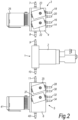
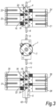
- the induction and discharge manifold blocks form respective modules or units which are mounted together with a pump unit disposed therebetween to provide a simple and compact assembly.
- the milk source is conveniently a chamber for receiving a representative milk sample from the milking of an individual animal by an automatic milking machine, the chamber having an inlet for the milk to enter the chamber and an outlet at the bottom that is connected to a milk supply path in the induction system, which along with the other supply paths can be defined by a duct or passage in the induction manifold block.
- the chamber may have a closable connection to atmosphere for venting displaced air from the chamber as it is filled with milk.
- the induction system may include a drain path and a device, such as solenoid actuated membrane valve, for selectively opening and closing the drain path. If desired the drain path can also be opened to admit air into the milk collection chamber via the milk supply path and the milk outlet of the chamber, the air being drawn into the chamber by vacuum supplied from the automatic milking machine and bubbling through the milk in the chamber to agitate and mix the milk.
- a device such as solenoid actuated membrane valve
- the plurality of fluid sources connectable to the pump inlet through supply paths in the induction system may include a source of washing fluid, in which case the induction system may be equipped with a washing fluid pressure control device in the supply path for the washing fluid.
- the plurality of fluid sources may include alternatively or additionally a source of pressurised gas in particular air, and the induction system can include a pressure control device in the supply path for the pressurised gas, or a plurality of control devices for pressurised gas to be supplied at different pressures.
- the pressurised gas can also be used to push a milk sample discharged through a sample discharge path to an analysing means.
- the pressurised gas can also be used for drying the sample discharge paths and lines after they have been cleaned with washing fluid.
- the milk sampling system preferably includes a control devices which operates so that after delivery of a milk sample through at least one discharge path, washing fluid is supplied through the washing fluid supply path and is conveyed through the pump and through the at least one discharge path, and subsequently drying air is supplied through the pressurised gas supply path and is conducted through the pump and through the at least one discharge path.
- washing fluid By passing washing fluid through a milk sample discharge path after a sample has been discharged through that discharge path, the washing fluid will flush away any remnants of the milk sample from the discharge path before the next sample is discharged through this path. Passing a drying gas, such as air, through the discharge path after the washing fluid effectively removes any washing fluid. In this way one milk sample is prevented from contaminating a following milk sample and the milk samples will not be contaminated or diluted by the washing fluid either.
- the induction system can comprise a milk return path for returning milk to the automatic milking machine for it to be collected in the milk tank with other milk, and a device for selectively opening and closing the milk return path. In this way milk waste can be minimised.
- the discharge system may include a drain path through which milk or other liquid can be discharged to drain, and a device, such as a solenoid actuated membrane valve, for opening and closing the drain path.
- a device such as a solenoid actuated membrane valve
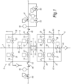
- a milk sampling system embodying the invention is illustrated in Figures 1 to 4 , and as shown it comprises a fluid conveying device with a pump unit 1 including metering pump 2, in particular a membrane pump calibrated to discharge a fixed quantity of liquid for each stroke of the pump, an induction system 3 including a manifold block 4, and a discharge system 5 including a manifold block 6.
- the manifold block 4 includes an inlet nipple 7 for connection to a milk source, to be described in more detail below, by a connecting tube, and an outlet nipple 8 for connection to an inlet nipple 9 of the pump unit 1 by a short connecting tube, not shown in Figs. 2-4 .
- the pump unit 1 has an outlet nipple 10 for connection to an inlet nipple 11 of the discharge manifold block 6 by another short connecting tube also not shown in Figs. 2-4 .
- Formed by ducts within the manifold block 4 are a milk supply path 12 which communicates with the inlet and outlet nipples 7, 8, a washing fluid supply path 13 which communicates with an inlet nipple 14 for washing fluid and with the outlet nipple 8, an air supply path 15 which communicates with an inlet nipple 16 for pressurised air and with the outlet nipple 8, a return milk path 17 which connects the milk supply path 12 to an outlet nipple 18, and a drain path 19 which connects the milk supply path 12 to an outlet nipple 20 for connection of a tube leading to drain.
- the washing fluid supply path 13, the air supply path 15, the return milk path 17 and the drain path 19 can be selectively opened and closed by respective solenoid actuated membrane valves 21, 22, 23 and 24, there being two valve actuators mounted on each of the opposite main faces of the manifold block 4.
- the milk supply path 12 is selectively openable and closable by a solenoid actuated membrane valve 25, the valve actuator being mounted to an edge face of the manifold block opposite that at which the nipples 14, 16, 18 and 20 are located.
- the manifold block 6 of the discharge system includes ducts forming a common discharge path 25 communicating with the inlet nipple 11, a first milk sample discharge path 27 connecting the common discharge path 26 to a first sample discharge nipple 28, a second milk sample discharge path 29 connecting the common discharge path 26 to a second sample discharge nipple 30, a third milk sample discharge path 31 connecting the common discharge path 26 to a third sample discharge nipple 32, and a fourth milk sample discharge path 33 connecting the common discharge path 26 to a fourth sample discharge nipple 34.
- the first, second, third and fourth sample discharge paths 27, 29, 31, 33 can be selectively opened and closed by respective solenoid actuated membrane valves 35, 36, 37, 38, there being two valve actuators mounted on each of the opposed main faces of the manifold block 6.
- a further duct in the manifold block 6 forms a drain path 39 connecting the common discharge path 26 to a nipple 40 to which a tube can be connected leading to drain.
- the drain path 39 is selectively openable and closable by a solenoid actuated membrane valve 41 mounted to an edge face of the manifold block 6 opposite that at which the sample discharge nipples 28, 30, 32 and 34 are disposed.
- Each of the valves 21-25, 35-38 and 41 is closed when its solenoid is not energised.
- the inlet nipple 7 of the induction manifold block 4 is connected by a tube to a bottom outlet 63 of a container or chamber 62 having an inlet 64 connected to a flow line 65 leading from an automatic milking machine, as shown in Figure 5 , for supply of milk into the chamber 62.
- the chamber 62 also has a vent opening connected by an air flow line 67 to atmosphere.
- the air flow line 67 can include a valve 68 for closing this flow line.
- the milk sampling system 100 embodying the invention is connected to collect and sample milk from the vacuum milking system of the automatic milking machine.
- the milking machine includes a receiver 140 for receiving milk extracted from the udder of an animal during milking.
- An outlet of the receiver 40 is connected to the inlet of a milk pump 141, the main outlet of which is arranged to be connected to a bulk storage tank 142 via a milk line 143 and valve 158.
- Branched from the milk line 143 are a drain line 144 equipped with a drain valve 159 and through which milk can be discharged if it is unsuitable for collection in the bulk storage tank, and a mixing line 145 which leads back to the receiver 140 and includes a valve 146 to open and close the mixing line 145.
- the pump 141 is equipped with a second outlet 147 through which an amount of milk proportional to the total amount of milk passing through the pump is discharged, the pump outlet 147 being connected to the inlet flow line 65 of the milk sampling system through a sampling valve 148. Also connected to the flow line 65 downstream of the valve 48 is an air pressure supply line 149 fitted with a valve 150 and a check valve 155.
- the outlet nipple 18 of the milk return path 17 of the sampling apparatus is connected to the pump discharge line 143 by a tube 160 and via a check valve 151. Also connected to the pump discharge line 143 is an air pressure supply line 152 with control valve 153 and check valve 154 for supply of purging air at the end of milking.
- the receiver 140 is subjected to the milking vacuum and receives the milk extracted from the udder of the animal by the teat cups and the vacuum applied thereto.
- a minor sampling portion of the milk can be directed to the milk sampling apparatus 100, but different methods may be followed in this respect.
- the milk mixing line 145 is not used, and the milk is simply pumped from the receiver 140 to the milk tank 142 (unless it is to be discharged to drain) and a proportional amount of milk is discharged through the second pump outlet 147 and through the flow line 165 into the chamber 62 of the sampling apparatus.
- the sample valve 148 may be opened after a short delay to minimise carry over of milk from the previous milking of another animal.
- the milk may be collected in the receiver 140 and circulated by the pump 141 and the mixing line 145 by opening valve 146 while valves 158 and 159 remain closed.
- This circulation of milk ensures good mixing of the milk so that the entire volume of milk is of substantially uniform consistency whereas the consistency generally varies in the course of emptying an udder.
- the valve 146 is closed and the valve 158 is opened so that the milk will be transported by the pump 141 to the bulk milk tank 142.
- a substantially fixed quantity of the milk can be transferred through the flow line 65 into the chamber 62 of the sampling apparatus, or a proportional amount of the milk extracted from the udder during milking can be transferred to the chamber 62 of the milk sampling apparatus.
- valves 21-25, 35-38 and 41 of the sampling system remain closed, but the valve 68 is held open to allow air from inside the chamber to escape to atmosphere to avoid a pressure build up in the chamber as it fills with milk. If the amount of milk delivered into the chamber exceeds the maximum volume of the chamber the surplus milk may be allowed to overflow through the flow line 67 connected to atmosphere.
- the milk collected in the chamber can be agitated and mixed to ensure that the milk samples to be delivered will be representative of the composition of all of the milk collected in the chamber.
- solenoid valve 24 of the drain path 19 in induction manifold block 4 can be opened so that air is drawn in through the line 24 and bubbles upwardly through the milk in the chamber 62 to mix the milk. After an adequate mixing time the valve 24 is closed again.
- By closing valve 148 and opening the air valve 155 air under pressure can if desired be delivered into the chamber 62 above the surface level of the milk, to assist subsequent delivery of milk through the outlet 63 of the chamber.
- the sample discharge nipples 28, 30, 32, 34 can be connected by tubes to respective milk analysing means A1, A2, A3, A4 such as for measuring different components or parameters of the milk, as described in EP 1381269 B1 .
- a discrete milk sample can be discharged to any one or more of the four analysing means A1-A4 as may be desired by appropriate operation of the control device of the milk sampling system.
- the control device or control unit is connected to the computer system of the automatic milking machine for receiving commands as to the samples to be discharged.
- the discharge of the one or more samples can commence.
- the valves 25 and 41 are opened and the pump 2 is operated to pump a quantity of milk from the chamber 62 into the sampling apparatus sufficient to pre-fill the sampling system with milk, after which the drain valve 41 is closed to prevent any further milk discharge to drain and the pump is stopped.
- the valve 35 is opened and the pump 2 is operated so that a predetermined quantity of milk is delivered through the discharge path 27 to the nipple 28.
- the valve 25 in the milk supply path is then closed and the pump is stopped.
- valve 22 in the air supply path is opened and the pump 2 is operated again so that air at the pressure set by the first pressure regulator 47 is admitted and is passed through the pump so that the milk sample is pumped and pushed by the air through the first discharge path 27 to the first analysing means A1.
- the valves 22 and 35 are closed and the pump is stopped when the milk sample has been pumped/pushed to the analyser.
- milk remaining in the chamber 62 can be returned to the automatic milking machine to be conveyed to the bulk tank 142.
- the valve 23 in the milk return path 17 is opened.
- the metering pump 2 is not required to return the excess milk, this instead being achieved as a result of the air under pressure supplied into the chamber 62 from the air pressure supply line 149 and through the flow line 65.
- the milk in the chamber 2 is to be dumped, e.g. if it is judged to be of too poor quality to be transported to the bulk milk tank 142, it can be directed to drain by opening the valve 24 in the drain path 19.
- milk in the sampling apparatus can also be directed to drain downstream of the pump 2 by opening the valve 41 in the drain path 39 of the discharge manifold block 6.
- the milk sample paths can be flushed clean and dried in preparation for delivery of samples of milk from another animal.
- the valve 21 in the cleaning water supply path 13 is opened, the valve 35 in the first sample discharge path 27 (if a sample was discharged through this path) is opened and the pump 2 is turned on.
- the valve 35 is closed and the valve 36 in the second sample discharge path is opened (if this path is to be flushed with water).
- the valve 37 is opened.
- valve 37 When the third discharge path has been suitably flushed with water the valve 37 is closed again and the valve 38 can be opened to flush with cleaning water the fourth sample discharge path 33. After appropriate flow of water through the fourth sample discharge path the valve 38 is closed again.
- the flushing water can be supplied for flushing clean, that is to remove any milk sample remnants from each of the sample discharge paths through which samples were discharged during the previous milk sampling.
- the valve 41 can be opened so that cleaning water passes through and flushes away any remaining milk in the drain path 39.
- the valve 21 is then closed to shut off the water supply, the pump 2 is turned off and the drain valve 41 is closed.
- the same sequence of valve operations can be followed as that applied for flushing the sample discharge paths with water, but with the valve 22 in the air supply path 15 instead of the water valve 21 opened.
- the milk sample discharge paths can be dried and any risk of the subsequent milk samples delivered to the analysing means being contaminated or diluted with water used for flushing is avoided.
- the air pressure control valve 52 is opened so that the air is delivered into the air supply path at the pressure set by the second pressure regulator 50.
- the sampling system is ready for sampling the milk obtained from the next animal milked by the automated milked machine.
- the filling of the chamber 2 with the milk of the next animal can take place during the water flushing and drying of the sample discharge paths and lines to the analysing means.
Landscapes
- Life Sciences & Earth Sciences (AREA)
- Animal Husbandry (AREA)
- Environmental Sciences (AREA)
- Hydrology & Water Resources (AREA)
- Physics & Mathematics (AREA)
- Health & Medical Sciences (AREA)
- Chemical & Material Sciences (AREA)
- Analytical Chemistry (AREA)
- Biochemistry (AREA)
- General Health & Medical Sciences (AREA)
- General Physics & Mathematics (AREA)
- Immunology (AREA)
- Pathology (AREA)
- Sampling And Sample Adjustment (AREA)
Claims (10)
- System zur Entnahme von Milchproben (100), umfassend eine Fluidfördervorrichtung, die angeordnet ist, um Milch von einer automatischen Melkmaschine aufzunehmen, und eine Steuervorrichtung, die konfiguriert ist, um die Fluidfördervorrichtung zu steuern, um separate Proben der Milch an die jeweiligen Abgabewege zur Analyse durch die jeweiligen Milchanalysemittel (A1, A2, A3, A4) zu übermitteln, wobei die Fluidfördervorrichtung eine Pumpe (2) umfasst, die einen Einlass, der mit einem Ansaugsystem verbunden ist, und einen Auslass aufweist, der mit einem Abgabesystem verbunden ist, wobei das Ansaugsystem (3) Zufuhrwege aufweist, die angeordnet sind, um den Pumpeneinlass selektiv mit einer Vielzahl von Fluidquellen zu verbinden, einschließlich einer Milchquelle, wobei das Ansaugsystem (3) einen Verteilerblock (4) umfasst, der Vorrichtungen zum selektiven Öffnen und Schließen der Zufuhrwege für Milch trägt, wobei mindestens eine der Vorrichtungen zum selektiven Öffnen und Schließen der Zufuhrwege ein Magnetventil (21, 22, 23, 24, 25) umfasst, und wobei das Abgabesystem (5) eine Vielzahl von Abgabewegen aufweist, die angeordnet sind, um nacheinander separate Milchproben an die jeweiligen Abgabewege zur Analyse durch die jeweiligen Milchanalysemittel zu liefern, wobei das Abgabesystem (5) einen Verteilerblock (6) umfasst, der Vorrichtungen zum selektiven Öffnen und Schließen der Abgabewege trägt, und wobei mindestens eine der Vorrichtungen zum selektiven Öffnen und Schließen eines der Abgabewege ein Magnetventil (35, 36, 37, 38) umfasst, und wobei zum Zeitpunkt der Entnahme der Milchprobe aus dem Melken eines einzelnen Tieres eine separate Milchprobe durch Betätigung der Steuervorrichtung des Systems zur Entnahme von Milchproben an ein beliebiges oder mehrere der Analysevorrichtungen abgelassen werden kann, wobei die Steuervorrichtung mit dem Computersystem der automatischen Melkmaschine zum Empfangen von Befehlen in Bezug auf die Proben, die abgelassen werden sollen, verbunden ist; wobei Verteilerblöcke (4, 6) des Ansaug- und Abgabesystems (3, 5) mit einer Einheit aneinander angebracht sind, die die Pumpe (2) umfasst, die dazwischen positioniert ist.
- System zur Entnahme von Milchproben (100) nach Anspruch 1, wobei die Pumpe (2) eine Dosierpumpe ist.
- System zur Entnahme von Milchproben (100) nach Anspruch 1 oder 2, wobei die Pumpe (2) eine Membranpumpe ist.
- System zur Entnahme von Milchproben (100) nach einem der vorhergehenden Ansprüche, wobei das Abgabesystem einen Abflussweg (39) und eine Vorrichtung (41) zum Schließen des Ablasswegs (39) während der Abgabe einer Milchprobe durch einen Abflussweg beinhaltet.
- System zur Entnahme von Milchproben (100) nach einem der Ansprüche 1 bis 4, wobei das Ansaugsystem (3) einen Abflussweg (19) und eine Vorrichtung zum selektiven Öffnen und Schließen der Verbindung zwischen dem Abflussweg (19) und dem Milchzufuhrweg (12) beinhaltet.
- System zur Entnahme von Milchproben nach einem der Ansprüche 1 bis 5, wobei das Ansaugsystem einen Milchrückführweg und eine Vorrichtung zum selektiven Öffnen und Schließen der Verbindung zwischen dem Milchrückführweg und dem Milchzufuhrweg beinhaltet.
- System zur Entnahme von Milchproben nach einem der Ansprüche 1 bis 6, wobei die Vielzahl von Fluidquellen eine Quelle von Waschfluid beinhaltet und das Ansaugsystem eine Steuervorrichtung für den Waschfluiddruck in dem Zufuhrweg für Waschfluid beinhaltet.
- System zur Entnahme von Milchproben nach einem der Ansprüche 1 bis 7, wobei die Vielzahl von Fluidquellen eine Quelle von Druckgas beinhaltet und eine Vorrichtung zum selektiven Öffnen und Schließen des Druckgaszufuhrweges geöffnet werden kann, um Gas einzulassen, um eine Milchprobe, die durch einen Abgabeweg abgelassen wird, zu einem Analysemittel zu drücken.
- System zur Entnahme von Milchproben nach Anspruch 8, wobei das Ansaugsystem eine Drucksteuervorrichtung in dem Zufuhrweg für Druckgas beinhaltet und die Druckgassteuervorrichtung bedienbar ist, um Gas bei verschiedenen Drücken zu liefern.
- System zur Entnahme von Milchproben nach Anspruch 7 und 8, wobei die Steuervorrichtung die Fluidfördervorrichtung steuert, sodass nach Bereitstellung einer Milchprobe durch mindestens einen Abgabeweg Waschfluid durch den Waschfluidzufuhrweg bereitgestellt wird und durch die Pumpe und durch den mindestens einen Abgabeweg gefördert wird und Luft zum Trocknen durch den Druckgaszufuhrweg bereitgestellt wird und durch die Pumpe und durch den mindestens einen Abgabeweg geleitet wird.
Applications Claiming Priority (3)
| Application Number | Priority Date | Filing Date | Title |
|---|---|---|---|
| GBGB1021826.1A GB201021826D0 (en) | 2010-12-21 | 2010-12-21 | Milk sampling |
| US201061426120P | 2010-12-22 | 2010-12-22 | |
| PCT/SE2011/051546 WO2012087235A1 (en) | 2010-12-21 | 2011-12-20 | Milk sampling |
Publications (3)
| Publication Number | Publication Date |
|---|---|
| EP2654411A1 EP2654411A1 (de) | 2013-10-30 |
| EP2654411B1 EP2654411B1 (de) | 2018-11-28 |
| EP2654411B2 true EP2654411B2 (de) | 2025-04-23 |
Family
ID=43598879
Family Applications (1)
| Application Number | Title | Priority Date | Filing Date |
|---|---|---|---|
| EP11811191.3A Active EP2654411B2 (de) | 2010-12-21 | 2011-12-20 | Entnahme von milchproben |
Country Status (11)
| Country | Link |
|---|---|
| US (1) | US9448142B2 (de) |
| EP (1) | EP2654411B2 (de) |
| JP (1) | JP2014500039A (de) |
| CN (1) | CN103228128B (de) |
| AU (1) | AU2011345387B2 (de) |
| BR (1) | BR112013015834A2 (de) |
| CA (1) | CA2822183C (de) |
| GB (1) | GB201021826D0 (de) |
| NZ (1) | NZ610292A (de) |
| RU (1) | RU2013133460A (de) |
| WO (1) | WO2012087235A1 (de) |
Families Citing this family (14)
| Publication number | Priority date | Publication date | Assignee | Title |
|---|---|---|---|---|
| JP5879626B2 (ja) * | 2012-11-16 | 2016-03-08 | オリオン機械株式会社 | ミルクサンプリング装置 |
| EP3004318B1 (de) * | 2013-06-06 | 2019-10-09 | Bend Research, Inc. | Aseptisches probenentnahmemodul und verteiler |
| WO2016063112A1 (en) * | 2014-10-24 | 2016-04-28 | Vestergaard Company A/S | Method of sampling de-icing fluid and system for sampling de-icing fluid |
| US10721904B2 (en) * | 2014-12-30 | 2020-07-28 | Delaval Holding Ab | Method for sampling of milk in a milking machine and a milking machine |
| EP3337312B1 (de) * | 2015-08-20 | 2020-09-23 | DeLaval Holding AB | Verteilungseinheit für milchproben |
| IL246617B2 (en) * | 2016-07-05 | 2023-10-01 | Eyal Brayer | Means and Methods for Free Dome Range |
| DE102017214337A1 (de) * | 2017-08-17 | 2019-02-21 | Lactocorder Ag | Probenentnahmevorrichtung zur Entnahme einer repräsentativen Milchprobe und Verfahren zur Entnahme von repräsentativen Milchproben |
| NL2021686B1 (en) * | 2018-09-24 | 2020-05-07 | Lely Patent Nv | Milking system with detection system |
| CN112839508B (zh) * | 2018-10-25 | 2023-02-03 | 利拉伐控股有限公司 | 用于奶样品的分配单元 |
| EP3869945B1 (de) * | 2018-10-25 | 2025-01-08 | DeLaval Holding AB | Milchprobenentnahmegerät bestehend aus einer verteilungseinheit für milchproben mit zwei getrennten teilen |
| NL2026979B1 (nl) * | 2020-11-25 | 2022-07-04 | Lely Patent Nv | Automatische melkklep |
| NL2027809B1 (nl) * | 2021-03-23 | 2022-10-07 | Lely Patent Nv | Melkmonsternameinrichting en melksysteem daarmee |
| CN114894551B (zh) * | 2022-05-04 | 2024-07-23 | 赛摩智能科技集团股份有限公司 | 一种原奶罐车自动化取样系统 |
| NL2033548B1 (nl) * | 2022-11-17 | 2024-05-28 | Lely Patent Nv | Separatiemelkopvangsysteem en melksysteem daarmee |
Citations (1)
| Publication number | Priority date | Publication date | Assignee | Title |
|---|---|---|---|---|
| WO2005020674A1 (en) † | 2003-08-29 | 2005-03-10 | David Eric Akerman | Milk sampling and testing |
Family Cites Families (24)
| Publication number | Priority date | Publication date | Assignee | Title |
|---|---|---|---|---|
| SU1428318A1 (ru) | 1986-12-10 | 1988-10-07 | Оренбургский сельскохозяйственный институт | Устройство дл отбора проб молока на анализ |
| US4900683A (en) | 1986-12-16 | 1990-02-13 | Ciba-Geigy Corporation | Process for preparation of samples for analysis |
| SU1731106A1 (ru) | 1990-04-17 | 1992-05-07 | Воронежский сельскохозяйственный институт им.К.Д.Глинки | Молочно-контрольна пластинка дл диагностических исследований молока на мастит |
| WO1992015196A1 (en) | 1991-03-05 | 1992-09-17 | Rj Fullwood & Bland Limited | Milking sampling for diagnostic purposes |
| US5441071A (en) * | 1994-05-04 | 1995-08-15 | Mclane Research Laboratories, Inc. | Automated water sample collecting system |
| DE4438434C1 (de) | 1994-10-28 | 1996-03-14 | Jansky Gmbh | Vorrichtung zur Entnahme einer Probe in einer Milchsammelanlage |
| NL1006711C2 (nl) | 1997-08-04 | 1999-02-08 | Nedap Nv | Systeem ter bewaking en besturing van eiwitbenutting bij dieren. |
| FR2779824B1 (fr) | 1998-06-15 | 2000-07-21 | Air Liquide | Installation d'analyse d'atmosphere |
| ATE228294T1 (de) | 1998-11-05 | 2002-12-15 | Chemometec As | Ein system für regulation der handhabung von dem milch während des melkprozes und eine methode für regulation von diesem prozess |
| AU2001224002A1 (en) | 2000-03-07 | 2001-09-17 | Nihon University, School Juridical Person | Milking device for laboratory animals |
| SE517144C2 (sv) | 2000-04-03 | 2002-04-23 | Delaval Holding Ab | Anordning och förfarande för provtagning av mjölk |
| FR2815719B1 (fr) | 2000-10-24 | 2003-01-17 | Junior Instruments | Dispositif de pipetage automatique avec rincage |
| AU2002237205B8 (en) | 2001-03-07 | 2006-01-12 | Lattec I/S | System for optimising the production performance of a milk producing animal herd |
| SE0201215D0 (sv) * | 2002-04-23 | 2002-04-23 | Delaval Holding Ab | A device and a method for sampling of milk |
| US7162971B2 (en) * | 2002-12-19 | 2007-01-16 | Lattec I/S | Milk conveyer device |
| AU2003291968C1 (en) | 2002-12-19 | 2010-07-29 | Lattec I/S | A milk conveyer device |
| DE102004001188A1 (de) | 2003-01-03 | 2004-08-19 | Westfaliasurge Gmbh | Vorrichtung und Verfahren zum Bestimmen des Gesundheitsstatus eines Tieres |
| GB0313759D0 (en) | 2003-06-13 | 2003-07-23 | The Technology Partnership Plc | Fluid sampling components |
| NZ531794A (en) | 2004-03-25 | 2006-02-24 | Sensortec Ltd | Sample mechanism with integrated liquid detection |
| CA2577890C (en) | 2004-08-26 | 2015-03-24 | Monsanto Technology Llc | Automated seed sampler and methods of sampling, testing and bulking seeds |
| DE102005026723A1 (de) | 2005-06-09 | 2006-12-14 | Westfaliasurge Gmbh | Verfahren zur rechnergestützten Mastitiserkennung |
| US20070227452A1 (en) * | 2006-03-31 | 2007-10-04 | Tucker George H | Adaptive milking system |
| US20090007847A1 (en) * | 2007-07-07 | 2009-01-08 | Arkadi Relin | Method of dynamic milking |
| CN101526541A (zh) | 2009-04-01 | 2009-09-09 | 宇星科技发展(深圳)有限公司 | 室内空气质量检测装置 |
-
2010
- 2010-12-21 GB GBGB1021826.1A patent/GB201021826D0/en not_active Ceased
-
2011
- 2011-12-20 WO PCT/SE2011/051546 patent/WO2012087235A1/en not_active Ceased
- 2011-12-20 CN CN201180056995.8A patent/CN103228128B/zh active Active
- 2011-12-20 NZ NZ610292A patent/NZ610292A/en unknown
- 2011-12-20 AU AU2011345387A patent/AU2011345387B2/en active Active
- 2011-12-20 RU RU2013133460/13A patent/RU2013133460A/ru not_active Application Discontinuation
- 2011-12-20 US US13/991,449 patent/US9448142B2/en active Active
- 2011-12-20 EP EP11811191.3A patent/EP2654411B2/de active Active
- 2011-12-20 CA CA2822183A patent/CA2822183C/en active Active
- 2011-12-20 JP JP2013546074A patent/JP2014500039A/ja active Pending
- 2011-12-20 BR BR112013015834A patent/BR112013015834A2/pt not_active IP Right Cessation
Patent Citations (1)
| Publication number | Priority date | Publication date | Assignee | Title |
|---|---|---|---|---|
| WO2005020674A1 (en) † | 2003-08-29 | 2005-03-10 | David Eric Akerman | Milk sampling and testing |
Also Published As
| Publication number | Publication date |
|---|---|
| RU2013133460A (ru) | 2015-01-27 |
| CA2822183A1 (en) | 2012-06-28 |
| US9448142B2 (en) | 2016-09-20 |
| CA2822183C (en) | 2019-03-26 |
| EP2654411A1 (de) | 2013-10-30 |
| US20130247692A1 (en) | 2013-09-26 |
| CN103228128B (zh) | 2016-09-21 |
| BR112013015834A2 (pt) | 2019-09-24 |
| GB201021826D0 (en) | 2011-02-02 |
| EP2654411B1 (de) | 2018-11-28 |
| JP2014500039A (ja) | 2014-01-09 |
| CN103228128A (zh) | 2013-07-31 |
| AU2011345387A1 (en) | 2013-05-30 |
| NZ610292A (en) | 2014-09-26 |
| AU2011345387B2 (en) | 2016-10-13 |
| WO2012087235A1 (en) | 2012-06-28 |
Similar Documents
| Publication | Publication Date | Title |
|---|---|---|
| EP2654411B1 (de) | Entnahme von milchproben | |
| US7690328B2 (en) | Milk conveyer device | |
| AU2010202499B2 (en) | A milk conveyer device | |
| US8701510B2 (en) | Smart milk sampler for VMS | |
| US9155281B2 (en) | Milking plant | |
| WO2005020674A1 (en) | Milk sampling and testing | |
| US20110120378A1 (en) | System and method for automatically obtaining a milk sample and performing cleaning | |
| WO2004032608A1 (en) | A milking plant | |
| JP2009291129A (ja) | 搾乳情報入力表示装置 | |
| US10721904B2 (en) | Method for sampling of milk in a milking machine and a milking machine |
Legal Events
| Date | Code | Title | Description |
|---|---|---|---|
| PUAI | Public reference made under article 153(3) epc to a published international application that has entered the european phase |
Free format text: ORIGINAL CODE: 0009012 |
|
| 17P | Request for examination filed |
Effective date: 20130708 |
|
| AK | Designated contracting states |
Kind code of ref document: A1 Designated state(s): AL AT BE BG CH CY CZ DE DK EE ES FI FR GB GR HR HU IE IS IT LI LT LU LV MC MK MT NL NO PL PT RO RS SE SI SK SM TR |
|
| DAX | Request for extension of the european patent (deleted) | ||
| TPAC | Observations filed by third parties |
Free format text: ORIGINAL CODE: EPIDOSNTIPA |
|
| STAA | Information on the status of an ep patent application or granted ep patent |
Free format text: STATUS: EXAMINATION IS IN PROGRESS |
|
| 17Q | First examination report despatched |
Effective date: 20170109 |
|
| REG | Reference to a national code |
Ref country code: DE Ref legal event code: R079 Ref document number: 602011054362 Country of ref document: DE Free format text: PREVIOUS MAIN CLASS: A01J0005040000 Ipc: G01N0001100000 |
|
| GRAP | Despatch of communication of intention to grant a patent |
Free format text: ORIGINAL CODE: EPIDOSNIGR1 |
|
| STAA | Information on the status of an ep patent application or granted ep patent |
Free format text: STATUS: GRANT OF PATENT IS INTENDED |
|
| RIC1 | Information provided on ipc code assigned before grant |
Ipc: G01N 1/10 20060101AFI20180612BHEP Ipc: A01J 5/04 20060101ALI20180612BHEP |
|
| INTG | Intention to grant announced |
Effective date: 20180705 |
|
| GRAS | Grant fee paid |
Free format text: ORIGINAL CODE: EPIDOSNIGR3 |
|
| GRAA | (expected) grant |
Free format text: ORIGINAL CODE: 0009210 |
|
| STAA | Information on the status of an ep patent application or granted ep patent |
Free format text: STATUS: THE PATENT HAS BEEN GRANTED |
|
| AK | Designated contracting states |
Kind code of ref document: B1 Designated state(s): AL AT BE BG CH CY CZ DE DK EE ES FI FR GB GR HR HU IE IS IT LI LT LU LV MC MK MT NL NO PL PT RO RS SE SI SK SM TR |
|
| REG | Reference to a national code |
Ref country code: GB Ref legal event code: FG4D |
|
| REG | Reference to a national code |
Ref country code: CH Ref legal event code: EP |
|
| REG | Reference to a national code |
Ref country code: AT Ref legal event code: REF Ref document number: 1070796 Country of ref document: AT Kind code of ref document: T Effective date: 20181215 |
|
| REG | Reference to a national code |
Ref country code: NL Ref legal event code: FP |
|
| REG | Reference to a national code |
Ref country code: DE Ref legal event code: R096 Ref document number: 602011054362 Country of ref document: DE |
|
| REG | Reference to a national code |
Ref country code: IE Ref legal event code: FG4D |
|
| REG | Reference to a national code |
Ref country code: LT Ref legal event code: MG4D |
|
| REG | Reference to a national code |
Ref country code: AT Ref legal event code: MK05 Ref document number: 1070796 Country of ref document: AT Kind code of ref document: T Effective date: 20181128 |
|
| PG25 | Lapsed in a contracting state [announced via postgrant information from national office to epo] |
Ref country code: ES Free format text: LAPSE BECAUSE OF FAILURE TO SUBMIT A TRANSLATION OF THE DESCRIPTION OR TO PAY THE FEE WITHIN THE PRESCRIBED TIME-LIMIT Effective date: 20181128 Ref country code: AT Free format text: LAPSE BECAUSE OF FAILURE TO SUBMIT A TRANSLATION OF THE DESCRIPTION OR TO PAY THE FEE WITHIN THE PRESCRIBED TIME-LIMIT Effective date: 20181128 Ref country code: LT Free format text: LAPSE BECAUSE OF FAILURE TO SUBMIT A TRANSLATION OF THE DESCRIPTION OR TO PAY THE FEE WITHIN THE PRESCRIBED TIME-LIMIT Effective date: 20181128 Ref country code: NO Free format text: LAPSE BECAUSE OF FAILURE TO SUBMIT A TRANSLATION OF THE DESCRIPTION OR TO PAY THE FEE WITHIN THE PRESCRIBED TIME-LIMIT Effective date: 20190228 Ref country code: IS Free format text: LAPSE BECAUSE OF FAILURE TO SUBMIT A TRANSLATION OF THE DESCRIPTION OR TO PAY THE FEE WITHIN THE PRESCRIBED TIME-LIMIT Effective date: 20190328 Ref country code: FI Free format text: LAPSE BECAUSE OF FAILURE TO SUBMIT A TRANSLATION OF THE DESCRIPTION OR TO PAY THE FEE WITHIN THE PRESCRIBED TIME-LIMIT Effective date: 20181128 Ref country code: BG Free format text: LAPSE BECAUSE OF FAILURE TO SUBMIT A TRANSLATION OF THE DESCRIPTION OR TO PAY THE FEE WITHIN THE PRESCRIBED TIME-LIMIT Effective date: 20190228 Ref country code: HR Free format text: LAPSE BECAUSE OF FAILURE TO SUBMIT A TRANSLATION OF THE DESCRIPTION OR TO PAY THE FEE WITHIN THE PRESCRIBED TIME-LIMIT Effective date: 20181128 Ref country code: LV Free format text: LAPSE BECAUSE OF FAILURE TO SUBMIT A TRANSLATION OF THE DESCRIPTION OR TO PAY THE FEE WITHIN THE PRESCRIBED TIME-LIMIT Effective date: 20181128 |
|
| PG25 | Lapsed in a contracting state [announced via postgrant information from national office to epo] |
Ref country code: RS Free format text: LAPSE BECAUSE OF FAILURE TO SUBMIT A TRANSLATION OF THE DESCRIPTION OR TO PAY THE FEE WITHIN THE PRESCRIBED TIME-LIMIT Effective date: 20181128 Ref country code: SE Free format text: LAPSE BECAUSE OF FAILURE TO SUBMIT A TRANSLATION OF THE DESCRIPTION OR TO PAY THE FEE WITHIN THE PRESCRIBED TIME-LIMIT Effective date: 20181128 Ref country code: AL Free format text: LAPSE BECAUSE OF FAILURE TO SUBMIT A TRANSLATION OF THE DESCRIPTION OR TO PAY THE FEE WITHIN THE PRESCRIBED TIME-LIMIT Effective date: 20181128 Ref country code: GR Free format text: LAPSE BECAUSE OF FAILURE TO SUBMIT A TRANSLATION OF THE DESCRIPTION OR TO PAY THE FEE WITHIN THE PRESCRIBED TIME-LIMIT Effective date: 20190301 Ref country code: PT Free format text: LAPSE BECAUSE OF FAILURE TO SUBMIT A TRANSLATION OF THE DESCRIPTION OR TO PAY THE FEE WITHIN THE PRESCRIBED TIME-LIMIT Effective date: 20190328 |
|
| PG25 | Lapsed in a contracting state [announced via postgrant information from national office to epo] |
Ref country code: DK Free format text: LAPSE BECAUSE OF FAILURE TO SUBMIT A TRANSLATION OF THE DESCRIPTION OR TO PAY THE FEE WITHIN THE PRESCRIBED TIME-LIMIT Effective date: 20181128 Ref country code: PL Free format text: LAPSE BECAUSE OF FAILURE TO SUBMIT A TRANSLATION OF THE DESCRIPTION OR TO PAY THE FEE WITHIN THE PRESCRIBED TIME-LIMIT Effective date: 20181128 Ref country code: CZ Free format text: LAPSE BECAUSE OF FAILURE TO SUBMIT A TRANSLATION OF THE DESCRIPTION OR TO PAY THE FEE WITHIN THE PRESCRIBED TIME-LIMIT Effective date: 20181128 |
|
| REG | Reference to a national code |
Ref country code: CH Ref legal event code: PL |
|
| REG | Reference to a national code |
Ref country code: DE Ref legal event code: R026 Ref document number: 602011054362 Country of ref document: DE |
|
| PG25 | Lapsed in a contracting state [announced via postgrant information from national office to epo] |
Ref country code: RO Free format text: LAPSE BECAUSE OF FAILURE TO SUBMIT A TRANSLATION OF THE DESCRIPTION OR TO PAY THE FEE WITHIN THE PRESCRIBED TIME-LIMIT Effective date: 20181128 Ref country code: SK Free format text: LAPSE BECAUSE OF FAILURE TO SUBMIT A TRANSLATION OF THE DESCRIPTION OR TO PAY THE FEE WITHIN THE PRESCRIBED TIME-LIMIT Effective date: 20181128 Ref country code: LU Free format text: LAPSE BECAUSE OF NON-PAYMENT OF DUE FEES Effective date: 20181220 Ref country code: MC Free format text: LAPSE BECAUSE OF FAILURE TO SUBMIT A TRANSLATION OF THE DESCRIPTION OR TO PAY THE FEE WITHIN THE PRESCRIBED TIME-LIMIT Effective date: 20181128 Ref country code: EE Free format text: LAPSE BECAUSE OF FAILURE TO SUBMIT A TRANSLATION OF THE DESCRIPTION OR TO PAY THE FEE WITHIN THE PRESCRIBED TIME-LIMIT Effective date: 20181128 Ref country code: SM Free format text: LAPSE BECAUSE OF FAILURE TO SUBMIT A TRANSLATION OF THE DESCRIPTION OR TO PAY THE FEE WITHIN THE PRESCRIBED TIME-LIMIT Effective date: 20181128 |
|
| PLBI | Opposition filed |
Free format text: ORIGINAL CODE: 0009260 |
|
| PLAX | Notice of opposition and request to file observation + time limit sent |
Free format text: ORIGINAL CODE: EPIDOSNOBS2 |
|
| 26 | Opposition filed |
Opponent name: OCTROOIBUREAU VAN DER LELY N.V. Effective date: 20190828 |
|
| REG | Reference to a national code |
Ref country code: BE Ref legal event code: MM Effective date: 20181231 |
|
| PG25 | Lapsed in a contracting state [announced via postgrant information from national office to epo] |
Ref country code: SI Free format text: LAPSE BECAUSE OF FAILURE TO SUBMIT A TRANSLATION OF THE DESCRIPTION OR TO PAY THE FEE WITHIN THE PRESCRIBED TIME-LIMIT Effective date: 20181128 |
|
| PG25 | Lapsed in a contracting state [announced via postgrant information from national office to epo] |
Ref country code: BE Free format text: LAPSE BECAUSE OF NON-PAYMENT OF DUE FEES Effective date: 20181231 |
|
| PG25 | Lapsed in a contracting state [announced via postgrant information from national office to epo] |
Ref country code: CH Free format text: LAPSE BECAUSE OF NON-PAYMENT OF DUE FEES Effective date: 20181231 Ref country code: LI Free format text: LAPSE BECAUSE OF NON-PAYMENT OF DUE FEES Effective date: 20181231 |
|
| PG25 | Lapsed in a contracting state [announced via postgrant information from national office to epo] |
Ref country code: MT Free format text: LAPSE BECAUSE OF NON-PAYMENT OF DUE FEES Effective date: 20181220 |
|
| PLBB | Reply of patent proprietor to notice(s) of opposition received |
Free format text: ORIGINAL CODE: EPIDOSNOBS3 |
|
| PG25 | Lapsed in a contracting state [announced via postgrant information from national office to epo] |
Ref country code: TR Free format text: LAPSE BECAUSE OF FAILURE TO SUBMIT A TRANSLATION OF THE DESCRIPTION OR TO PAY THE FEE WITHIN THE PRESCRIBED TIME-LIMIT Effective date: 20181128 |
|
| PG25 | Lapsed in a contracting state [announced via postgrant information from national office to epo] |
Ref country code: HU Free format text: LAPSE BECAUSE OF FAILURE TO SUBMIT A TRANSLATION OF THE DESCRIPTION OR TO PAY THE FEE WITHIN THE PRESCRIBED TIME-LIMIT; INVALID AB INITIO Effective date: 20111220 Ref country code: CY Free format text: LAPSE BECAUSE OF FAILURE TO SUBMIT A TRANSLATION OF THE DESCRIPTION OR TO PAY THE FEE WITHIN THE PRESCRIBED TIME-LIMIT Effective date: 20181128 Ref country code: MK Free format text: LAPSE BECAUSE OF NON-PAYMENT OF DUE FEES Effective date: 20181128 |
|
| APBM | Appeal reference recorded |
Free format text: ORIGINAL CODE: EPIDOSNREFNO |
|
| APBP | Date of receipt of notice of appeal recorded |
Free format text: ORIGINAL CODE: EPIDOSNNOA2O |
|
| APAH | Appeal reference modified |
Free format text: ORIGINAL CODE: EPIDOSCREFNO |
|
| APBQ | Date of receipt of statement of grounds of appeal recorded |
Free format text: ORIGINAL CODE: EPIDOSNNOA3O |
|
| APBU | Appeal procedure closed |
Free format text: ORIGINAL CODE: EPIDOSNNOA9O |
|
| PGFP | Annual fee paid to national office [announced via postgrant information from national office to epo] |
Ref country code: IE Payment date: 20241112 Year of fee payment: 14 |
|
| PUAH | Patent maintained in amended form |
Free format text: ORIGINAL CODE: 0009272 |
|
| STAA | Information on the status of an ep patent application or granted ep patent |
Free format text: STATUS: PATENT MAINTAINED AS AMENDED |
|
| 27A | Patent maintained in amended form |
Effective date: 20250423 |
|
| AK | Designated contracting states |
Kind code of ref document: B2 Designated state(s): AL AT BE BG CH CY CZ DE DK EE ES FI FR GB GR HR HU IE IS IT LI LT LU LV MC MK MT NL NO PL PT RO RS SE SI SK SM TR |
|
| REG | Reference to a national code |
Ref country code: DE Ref legal event code: R102 Ref document number: 602011054362 Country of ref document: DE |
|
| REG | Reference to a national code |
Ref country code: NL Ref legal event code: FP |
|
| PGFP | Annual fee paid to national office [announced via postgrant information from national office to epo] |
Ref country code: NL Payment date: 20251112 Year of fee payment: 15 |
|
| PGFP | Annual fee paid to national office [announced via postgrant information from national office to epo] |
Ref country code: DE Payment date: 20251104 Year of fee payment: 15 |
|
| PGFP | Annual fee paid to national office [announced via postgrant information from national office to epo] |
Ref country code: GB Payment date: 20251114 Year of fee payment: 15 |
|
| PGFP | Annual fee paid to national office [announced via postgrant information from national office to epo] |
Ref country code: IT Payment date: 20251121 Year of fee payment: 15 |
|
| PGFP | Annual fee paid to national office [announced via postgrant information from national office to epo] |
Ref country code: FR Payment date: 20251117 Year of fee payment: 15 |