EP2654263A1 - Wireless network system compatible with multiple communications standards. - Google Patents
Wireless network system compatible with multiple communications standards. Download PDFInfo
- Publication number
- EP2654263A1 EP2654263A1 EP13163224.2A EP13163224A EP2654263A1 EP 2654263 A1 EP2654263 A1 EP 2654263A1 EP 13163224 A EP13163224 A EP 13163224A EP 2654263 A1 EP2654263 A1 EP 2654263A1
- Authority
- EP
- European Patent Office
- Prior art keywords
- standard
- basis
- wireless network
- network system
- mic
- Prior art date
- Legal status (The legal status is an assumption and is not a legal conclusion. Google has not performed a legal analysis and makes no representation as to the accuracy of the status listed.)
- Granted
Links
Images



Classifications
-
- H—ELECTRICITY
- H04—ELECTRIC COMMUNICATION TECHNIQUE
- H04W—WIRELESS COMMUNICATION NETWORKS
- H04W84/00—Network topologies
-
- H—ELECTRICITY
- H04—ELECTRIC COMMUNICATION TECHNIQUE
- H04L—TRANSMISSION OF DIGITAL INFORMATION, e.g. TELEGRAPHIC COMMUNICATION
- H04L69/00—Network arrangements, protocols or services independent of the application payload and not provided for in the other groups of this subclass
- H04L69/18—Multiprotocol handlers, e.g. single devices capable of handling multiple protocols
-
- H—ELECTRICITY
- H04—ELECTRIC COMMUNICATION TECHNIQUE
- H04L—TRANSMISSION OF DIGITAL INFORMATION, e.g. TELEGRAPHIC COMMUNICATION
- H04L1/00—Arrangements for detecting or preventing errors in the information received
- H04L1/12—Arrangements for detecting or preventing errors in the information received by using return channel
- H04L1/16—Arrangements for detecting or preventing errors in the information received by using return channel in which the return channel carries supervisory signals, e.g. repetition request signals
- H04L1/1607—Details of the supervisory signal
- H04L1/1671—Details of the supervisory signal the supervisory signal being transmitted together with control information
-
- H—ELECTRICITY
- H04—ELECTRIC COMMUNICATION TECHNIQUE
- H04L—TRANSMISSION OF DIGITAL INFORMATION, e.g. TELEGRAPHIC COMMUNICATION
- H04L67/00—Network arrangements or protocols for supporting network services or applications
- H04L67/01—Protocols
- H04L67/12—Protocols specially adapted for proprietary or special-purpose networking environments, e.g. medical networks, sensor networks, networks in vehicles or remote metering networks
-
- H—ELECTRICITY
- H04—ELECTRIC COMMUNICATION TECHNIQUE
- H04L—TRANSMISSION OF DIGITAL INFORMATION, e.g. TELEGRAPHIC COMMUNICATION
- H04L69/00—Network arrangements, protocols or services independent of the application payload and not provided for in the other groups of this subclass
- H04L69/22—Parsing or analysis of headers
Definitions
- the present disclosure relates to a wireless network system, more particularly, to a wireless network system to which a plurality of devices operating on the basis of incompatible and different standards are connected and the plurality of devices operating on the basis of the respective standards can operate stably while being mixed.
- Wireless field devices serving as a kind of wireless communication apparatus.
- devices designed on the basis of the industrial automation wireless communication standard ISA100.11a drawn up by the ISA100 Committee of the International Society of Automation (ISA) and issued on September, 2009 are used, for example.
- the process control system is affected by, for example:
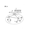
- FIG. 4 is a configuration explanatory view showing an example of a wireless network system having been used in the related art.
- a wireless network 1 is configured as a star-mesh topology composed of a plurality of I/O devices 2 to 6, routing devices 7 and 8, and a gateway 9.
- the I/O devices 2 to 6 have the wireless communication functions specified in the ISA100.11a and include various sensors, such as differential pressure/pressure transmitters and temperature transmitters, and various final control elements, such as valves and positioners.
- the gateway 9 has a function for connecting the wireless network 1 to a plant network 10 and also has a function for connecting the plurality of I/O devices 2 to 6 to a host application 11 provided for the plant network 10.
- the gateway 9 can be equipped with a system manager function and a security manager function for the wireless network topology as necessary, thereby being capable of managing the system and security of the wireless network topology. Moreover, the gateway 9 can be equipped with a backbone router function for performing connection to wireless connection devices.
- the host application 11 performs the setting of the routing devices 7 and 8 and the I/O devices 2 to 6, the diagnosis of devices, and the upgrade of firmware.
- the I/O devices 2 and 3 When attention is paid to wireless communication inside the wireless network 1 configured as shown in FIG. 4 , the I/O devices 2 and 3 perform communication with the gateway 9 via the routing device 8, and the I/O devices 4 to 6 perform communication with the gateway 9 via the routing device 7.
- the calculation result of an MIC Message Integrity Code: manipulation detection code
- an MIC is calculated on the basis of a cipher key common to the transmitting side, and the result of the calculation is compared and checked with the received MIC. The presence or absence of transmission errors is then judged depending on whether the two MICs are coincident with each other.
- FIG.5 is a block diagram showing an example of a processor 20 on the receiving side
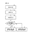
- FIG. 6 is a flowchart illustrating an example of the flow of MIC processing at the time when data is received in the processor 20 on the receiving side shown in FIG. 5 .
- a data receiver 21 receives data transmitted from the transmitting side (at step S1)
- an MIC detector 22 detects the MIC that was calculated and added to the data on the transmitting side (at step S2)
- an MIC calculator 23 calculates an MIC on the basis of the cipher key common to the transmitting side (at step S3).
- An MIC comparator 24 compares and checks the MIC detected by the MIC detector 22 with the MIC calculated by the MIC calculator 23, thereby judging whether the two are coincident with each other (at step S4).
- the MIC calculated by the MIC calculator 23 is added to an acknowledge signal ACK generated by an ACK generator 25 and then transmitted to the transmitting side via a data transmitter 26 (at step S5).
- the MIC calculated by the MIC calculator 23 is added to a non-acknowledge signal NACK generated by an NACK generator 27 and then transmitted to the transmitting side via the data transmitter 26 (at step S6).
- Non-patent Document 1 discloses a concept of a field wireless solution conforming to ISA100.11a and a concept of a field wireless system in which a central focus is placed on DCS.
- Non-patent Document 2 discloses a technology relating to wireless field devices and a field wireless system conforming to ISA100.11a.
- Patent Document 1 discloses a technology for preventing terminals from malfunctioning even in the case that a communication network is structured so that old terminals operating according to an old protocol existing already are mixed with new terminals adopting a new protocol that is made by modifying the old protocol.
- a wireless field device having been used from the beginning of the use of an existing process control system operates on the basis of the initial standard version ISA100.11a-2009, for example, but a wireless field device newly added to the existing process control system operates on the basis of the revised standard version ISA100.11a-2011 that is being revised.
- field devices operating on the basis of an existing standard and field devices operating on the basis of a revised new standard can be mixed in a process control system.
- Exemplary embodiments of the invention provide a wireless network system in which devices operating on the basis of an existing standard and devices operating on the basis of a revised new standard can be operated.
- a wireless network system comprises;
- the standard identifying module may be configured to identify the standard on the basis of a calculation result of a manipulation detection code.
- the incompatible and different standards may correspond to the old version and the new version of the industrial automation wireless communication standard ISA100.11a.
- the plurality of devices operating on the basis of the incompatible and different standards and mixedly connected to the same wireless network system can operate on the basis of the standards respectively identified.
- the devices operating on the basis of the existing standard can be mixed with the devices operating on the basis of the revised new standard in the same wireless network system.
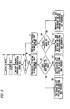
- FIG. 1 is a block diagram showing an example of a processor 30 on the receiving side in a device operating on a new version standard and to be used in the present invention.
- FIG. 2 is a flowchart illustrating an example of the flow of MIC processing at the time when data is received in the processor 30 on the receiving side shown in FIG. 1 .
- FIGS. 3A to 3C are data structures diagrams on the basis of the industrial automation wireless communication standard ISA100.11a.
- the processor 30 on the receiving side in the device operating on the basis of the new version standard and to be used in the present invention is provided with both an old version MIC calculator 35a and a new version MIC calculator 35b.
- a data receiver 31 receives data transmitted from the transmitting side (at step S1)
- an MIC detector 32 detects the MIC that was calculated and added to the data on the transmitting side (at step S2).
- a standard version identifier detector 33 detects the identifier representing the version of the wireless communication standard on the basis of which the received data is generated (at step S3).
- a standard version judgment section 34 judges whether the version of the standard is old (at step S4).
- FIG. 3A is a view showing the structure of a data frame DPDU (Datalink Protocol Data Unit) to be transmitted and received between devices at the DL levels (datalink layer levels) thereof.
- FIG. 3B is a view showing the structure of the DHDR frame of the revised standard version ISA 100.11a-2011
- FIG. 3C is a view showing the structure of the DOOR frame of the initial standard version ISA 100,11a-2009.
- DPDU Datalink Protocol Data Unit
- DHR is the header of DPDU and is composed of DHDR, DMXHR, DAUX, DROUT and DADDR.
- the identifier of the standard version (DL Version) of the industrial automation wireless communication standard ISA100.11a is included in the frame of DHDR.
- the value of the revised standard version ISA100.11a-2011 is "01" as shown in FIG. 3B
- the value of the initial standard version ISA100.11a-2009 is "00" as shown in FIG. 3C .
- the old version MIC calculator 35a calculates an MIC on the basis of the algorithm of the old version including a cipher key common to the transmitting side (at step S5).
- An MIC comparator 36 compares and checks the MIC detected by the MIC detector 32 with the MIC calculated by the old version MIC calculator 35a, thereby judging whether the two are coincident with each other (at step S6).
- the MIC calculated by the old version MIC calculator 35a is added to an acknowledge signal ACK generated by an ACK generator 37 and then transmitted to the transmitting side via a data transmitter 39 (at step S7).
- the MIC calculated by the old version MIC calculator 35a is added to a non-acknowledge signal NACK generated by an NACK generator 38 and then transmitted to the transmitting side via the data transmitter 39 (at step S8).
- the new version MIC calculator 35b calculates an MIC on the basis of the algorithm of the new version including a cipher key common to the transmitting side (at step S9).
- the MIC comparator 36 compares and checks the MIC detected by the MIC detector 32 with the MIC calculated by the new version MIC calculator 35b, thereby judging whether the two are coincident with each other (at step S10).
- the MIC calculated by the new version MIC calculator 35b is added to an acknowledge signal ACK generated by the ACK generator 37 and then transmitted to the transmitting side via the data transmitter 39 (at step S11).
- the MIC calculated by the new version MIC calculator 35b is added to a non-acknowledge signal NACK generated by the NACK generator 38 and then transmitted to the transmitting side via the data transmitter 39 (at step S12).
- the devices operating on the basis of the existing standard can be mixed with the devices operating on the revised new standard in the same wireless network system.
- the standard version (DL version) identifier is used as means for identifying the version of the standard when the MIC calculation processing is performed.
- a numerical value in data is different depending on the standard, it is not limited to use the standard version identifier, but either may be used.
- the version of the standard used by the communication partner may be judged on the basis of ACK/NACK retuned from the communication partner after the transmission of the result of the calculation on the basis of the MIC algorithm of either one of the versions of the standard. After the judgment, it may be possible that the pair of the identifier of the device and the version of the standard is stored, that the predetermined version of the standard is selected depending on the identifier of the device, and that an MIC is calculated on the basis of the algorithm of the selected version.
- Attribute ID is determined when an access is made to a parameter having Attribute ID being different depending on the version of the standard, it may be possible to use the version identification method used in the MIC processing.
- a parameter being different in each version of the standard is read beforehand and that the version of the standard is identified by the content of the response so that operation is performed accordingly.
- the present invention can realize a wireless network system in which devices operating on the basis of an existing standard and devices operating on the basis of a revised new standard can operate in the same system.
- the present invention is effective in the case that devices operating on the basis of a new standard are used in a process control system structured by an existing wireless network system in industrial automation.
Landscapes
- Engineering & Computer Science (AREA)
- Computer Networks & Wireless Communication (AREA)
- Signal Processing (AREA)
- Computer Security & Cryptography (AREA)
- Mobile Radio Communication Systems (AREA)
- Communication Control (AREA)
Abstract
Description
- The present disclosure relates to a wireless network system, more particularly, to a wireless network system to which a plurality of devices operating on the basis of incompatible and different standards are connected and the plurality of devices operating on the basis of the respective standards can operate stably while being mixed.
- Process control systems in recent industrial automation are frequently configured using wireless field devices serving as a kind of wireless communication apparatus. As these wireless field devices, devices designed on the basis of the industrial automation wireless communication standard ISA100.11a drawn up by the ISA100 Committee of the International Society of Automation (ISA) and issued on September, 2009 are used, for example.
- As a result that a related-art process control system is configured using wired field devices connected via cables, the process control system is affected by, for example:
- 1) Restriction on communication distance
- 2) Restriction on cable routing
-
FIG. 4 is a configuration explanatory view showing an example of a wireless network system having been used in the related art. InFIG. 4 , awireless network 1 is configured as a star-mesh topology composed of a plurality of I/O devices 2 to 6,routing devices gateway 9. - The I/
O devices 2 to 6 have the wireless communication functions specified in the ISA100.11a and include various sensors, such as differential pressure/pressure transmitters and temperature transmitters, and various final control elements, such as valves and positioners. - The
routing devices - The
gateway 9 has a function for connecting thewireless network 1 to aplant network 10 and also has a function for connecting the plurality of I/O devices 2 to 6 to ahost application 11 provided for theplant network 10. - Furthermore, the
gateway 9 can be equipped with a system manager function and a security manager function for the wireless network topology as necessary, thereby being capable of managing the system and security of the wireless network topology. Moreover, thegateway 9 can be equipped with a backbone router function for performing connection to wireless connection devices. - The
host application 11 performs the setting of therouting devices O devices 2 to 6, the diagnosis of devices, and the upgrade of firmware. - When attention is paid to wireless communication inside the
wireless network 1 configured as shown inFIG. 4 , the I/O devices gateway 9 via therouting device 8, and the I/O devices 4 to 6 perform communication with thegateway 9 via therouting device 7. - When the above-mentioned wireless communication is performed, in order that the presence or absence of transmission errors is identified accurately, the calculation result of an MIC (Message Integrity Code: manipulation detection code) based on a cipher set beforehand on the transmitting side is added and transmitted. Also on the receiving side, an MIC is calculated on the basis of a cipher key common to the transmitting side, and the result of the calculation is compared and checked with the received MIC. The presence or absence of transmission errors is then judged depending on whether the two MICs are coincident with each other.
-
FIG.5 is a block diagram showing an example of aprocessor 20 on the receiving side, andFIG. 6 is a flowchart illustrating an example of the flow of MIC processing at the time when data is received in theprocessor 20 on the receiving side shown inFIG. 5 . Referring toFIGS. 5 and6 , when adata receiver 21 receives data transmitted from the transmitting side (at step S1), anMIC detector 22 detects the MIC that was calculated and added to the data on the transmitting side (at step S2), and anMIC calculator 23 calculates an MIC on the basis of the cipher key common to the transmitting side (at step S3). - An
MIC comparator 24 compares and checks the MIC detected by theMIC detector 22 with the MIC calculated by theMIC calculator 23, thereby judging whether the two are coincident with each other (at step S4). - In the case that the two are coincident with each other, the MIC calculated by the
MIC calculator 23 is added to an acknowledge signal ACK generated by anACK generator 25 and then transmitted to the transmitting side via a data transmitter 26 (at step S5). - On the other hand, in the case that the two are not coincident with each other, the MIC calculated by the
MIC calculator 23 is added to a non-acknowledge signal NACK generated by anNACK generator 27 and then transmitted to the transmitting side via the data transmitter 26 (at step S6). - Non-patent
Document 1 discloses a concept of a field wireless solution conforming to ISA100.11a and a concept of a field wireless system in which a central focus is placed on DCS. - Non-patent
Document 2 discloses a technology relating to wireless field devices and a field wireless system conforming to ISA100.11a. -
Patent Document 1 discloses a technology for preventing terminals from malfunctioning even in the case that a communication network is structured so that old terminals operating according to an old protocol existing already are mixed with new terminals adopting a new protocol that is made by modifying the old protocol. -
- [Non-patent Document 1] "Field Wireless Solution Based on ISA100.11a to Innovate Instrumentation," prepared by Shuji Yamamoto and other two, Yokogawa Technical Report, Yokogawa Electric Corporation, 2010, Vol. 53, No. 2 (2010), p. 7 to p. 12
- [Non-patent Document 2] "World's First Wireless Field Instruments Based on ISA100.11a," prepared by Shuji Yamamoto and other three, Yokogawa Technical Report, Yokogawa Electric Corporation, 2010, Vol. 53, No. 2 (2010), p. 13 to p. 16
-
- [Patent Document 1]
JP-A-2008-154087 - The above-mentioned wireless communication standard has been reviewed and revised as appropriate so as to be able to cope with technological advances and environmental changes, for example.
- As a result, it is conceivable in some cases that a wireless field device having been used from the beginning of the use of an existing process control system operates on the basis of the initial standard version ISA100.11a-2009, for example, but a wireless field device newly added to the existing process control system operates on the basis of the revised standard version ISA100.11a-2011 that is being revised.
- In incompatible and different standards, such as the initial standard version ISA100.11a-2009 and the revised standard version ISA100.11a-2011, the standards are different from each other in the following points:
- a) different in the parameter that is used for MIC calculation
- b) different in the parameter ID (Attribute ID) required when making an access to the parameter possessed by a field device
- c) different in the data structure of the parameter possessed by a field device
- In this case, this can be solved by changing the firmware of all the existing field devices so that the devices operate on the basis of the revised standard ISA100.11a-2011. However, enormous cost is necessary to change the firmware of all the wireless field devices having been used from the beginning of the use of the existing process control system.
- Accordingly, it is desired that field devices operating on the basis of an existing standard and field devices operating on the basis of a revised new standard can be mixed in a process control system.
- Exemplary embodiments of the invention provide a wireless network system in which devices operating on the basis of an existing standard and devices operating on the basis of a revised new standard can be operated.
- A wireless network system according to an exemplary embodiment comprises;
- a plurality of devices operating on the basis of incompatible and different standards, wherein
- at least one of the devices comprises a standard identifying module configured to identify standards on the basis of parameters inherent and different in the respective standards.
- The standard identifying module may be configured to identify the standard on the basis of a calculation result of a manipulation detection code.
- The incompatible and different standards may correspond to the old version and the new version of the industrial automation wireless communication standard ISA100.11a.
- Consequently, the plurality of devices operating on the basis of the incompatible and different standards and mixedly connected to the same wireless network system can operate on the basis of the standards respectively identified.
- More specifically, in the case that field devices operating on the basis of a revised new standard are provided with, for example, a manipulation detection code calculation function operating on the basis of both the existing standard and the revised new standard, the devices operating on the basis of the existing standard can be mixed with the devices operating on the basis of the revised new standard in the same wireless network system.
-
-
FIG. 1 is a block diagram showing aprocessor 30 on a receiving side in a device operating on a new version standard according to an exemplary embodiment of the present invention. -
FIG. 2 is a flowchart illustrating a flow of MIC processing at the time when data is received in theprocessor 30 shown inFIG. 1 . -
FIGS. 3A to 3C are data structure diagrams on the basis of an industrial automation wireless communication standard ISA100.11a. -
FIG. 4 is a configuration explanatory view showing a wireless network system in the related art. -
FIG.5 is a block diagram showing aprocessor 20 on the receiving side in the related art. -
FIG. 6 is a flowchart illustrating a flow of MIC processing at the time when data is received in theprocessor 20 shown inFIG. 5 . - An embodiment access to the present invention will be described below in detail using the drawings.
FIG. 1 is a block diagram showing an example of aprocessor 30 on the receiving side in a device operating on a new version standard and to be used in the present invention.FIG. 2 is a flowchart illustrating an example of the flow of MIC processing at the time when data is received in theprocessor 30 on the receiving side shown inFIG. 1 .FIGS. 3A to 3C are data structures diagrams on the basis of the industrial automation wireless communication standard ISA100.11a. Theprocessor 30 on the receiving side in the device operating on the basis of the new version standard and to be used in the present invention is provided with both an oldversion MIC calculator 35a and a newversion MIC calculator 35b. - Referring to
FIGS. 1 and2 , when adata receiver 31 receives data transmitted from the transmitting side (at step S1), anMIC detector 32 detects the MIC that was calculated and added to the data on the transmitting side (at step S2).
On the other hand, from the structure of the data shown inFIG. 3A and received by thedata receiver 21, a standardversion identifier detector 33 detects the identifier representing the version of the wireless communication standard on the basis of which the received data is generated (at step S3). On the basis of the identifier detected by the standardversion identifier detector 33, a standardversion judgment section 34 judges whether the version of the standard is old (at step S4). -
FIG. 3A is a view showing the structure of a data frame DPDU (Datalink Protocol Data Unit) to be transmitted and received between devices at the DL levels (datalink layer levels) thereof.FIG. 3B is a view showing the structure of the DHDR frame of the revised standard version ISA 100.11a-2011, andFIG. 3C is a view showing the structure of the DOOR frame of the initial standard version ISA 100,11a-2009. - Targets to be authenticated by DMIC are MHR, DHR and DSDU (DL Service Unit) as shown in
FIG. 3A . DHR is the header of DPDU and is composed of DHDR, DMXHR, DAUX, DROUT and DADDR. - The identifier of the standard version (DL Version) of the industrial automation wireless communication standard ISA100.11a is included in the frame of DHDR. In other words, the value of the revised standard version ISA100.11a-2011 is "01" as shown in
FIG. 3B , and the value of the initial standard version ISA100.11a-2009 is "00" as shown inFIG. 3C . - Referring again to
FIGS. 1 and2 , in the case that the standardversion judgment section 34 judges that the version is old, the oldversion MIC calculator 35a calculates an MIC on the basis of the algorithm of the old version including a cipher key common to the transmitting side (at step S5). - An
MIC comparator 36 compares and checks the MIC detected by theMIC detector 32 with the MIC calculated by the oldversion MIC calculator 35a, thereby judging whether the two are coincident with each other (at step S6). - In the case that the two are coincident with each other, the MIC calculated by the old
version MIC calculator 35a is added to an acknowledge signal ACK generated by anACK generator 37 and then transmitted to the transmitting side via a data transmitter 39 (at step S7). - On the other hand, in the case that the two are not coincident with each other, the MIC calculated by the old
version MIC calculator 35a is added to a non-acknowledge signal NACK generated by anNACK generator 38 and then transmitted to the transmitting side via the data transmitter 39 (at step S8). - In contrast, in the case that the standard
version judgment section 34 judges that the version is new, the newversion MIC calculator 35b calculates an MIC on the basis of the algorithm of the new version including a cipher key common to the transmitting side (at step S9). - The
MIC comparator 36 compares and checks the MIC detected by theMIC detector 32 with the MIC calculated by the newversion MIC calculator 35b, thereby judging whether the two are coincident with each other (at step S10). - In the case that the two are coincident with each other, the MIC calculated by the new
version MIC calculator 35b is added to an acknowledge signal ACK generated by theACK generator 37 and then transmitted to the transmitting side via the data transmitter 39 (at step S11). - On the other hand, in the case that the two are not coincident with each other, the MIC calculated by the new
version MIC calculator 35b is added to a non-acknowledge signal NACK generated by theNACK generator 38 and then transmitted to the transmitting side via the data transmitter 39 (at step S12). - With this configuration, the devices operating on the basis of the existing standard can be mixed with the devices operating on the revised new standard in the same wireless network system.
- In the above-mentioned embodiment, the standard version (DL version) identifier is used as means for identifying the version of the standard when the MIC calculation processing is performed. However, in the case that, for example, a numerical value in data is different depending on the standard, it is not limited to use the standard version identifier, but either may be used.
- Furthermore, in the case that transmission is performed by a communication partner from an device conforming to a new standard and if the version of the standard is unknown, it may be possible to judge the version of the standard used by the communication partner on the basis of ACK/NACK retuned from the communication partner after the transmission of the result of the calculation on the basis of the MIC algorithm of either one of the versions of the standard. After the judgment, it may be possible that the pair of the identifier of the device and the version of the standard is stored, that the predetermined version of the standard is selected depending on the identifier of the device, and that an MIC is calculated on the basis of the algorithm of the selected version.
- Moreover, in the case that Attribute ID is determined when an access is made to a parameter having Attribute ID being different depending on the version of the standard, it may be possible to use the version identification method used in the MIC processing.
- Still further, it may be possible that a parameter being different in each version of the standard is read beforehand and that the version of the standard is identified by the content of the response so that operation is performed accordingly.
- As described above, the present invention can realize a wireless network system in which devices operating on the basis of an existing standard and devices operating on the basis of a revised new standard can operate in the same system. In particular, the present invention is effective in the case that devices operating on the basis of a new standard are used in a process control system structured by an existing wireless network system in industrial automation.
Claims (5)
- A wireless network system comprising:a plurality of devices operating on the basis of incompatible and different standards, whereinat least one of the devices comprises a standard identifying module configured to identify standards on the basis of parameters inherent and different in the respective standards.
- The wireless network system according to claim 1, wherein the standard identifying module is configured to identify the standard on the basis of a calculation result of a manipulation detection code.
- The wireless network system according to claim 1 or 2, wherein the incompatible and different standards correspond to the old version and the new version of the industrial automation wireless communication standard ISA100.11a.
- The wireless network system according to claim 1, wherein the standard identifying module includes a standard identifier detector configured to detect an identifier representing the standard on the basis of which a received data is generated, and a standard judgment module configured to judge the standard on the basis of the identifier detected by the standard identifier detector.
- The wireless network system according to claim 1, further comprising:a manipulation detection code calculator configured to calculate a manipulation detection code on the basis of an algorithm of the identified standard.
Applications Claiming Priority (1)
| Application Number | Priority Date | Filing Date | Title |
|---|---|---|---|
| JP2012092855A JP5720615B2 (en) | 2012-04-16 | 2012-04-16 | Wireless network system |
Publications (2)
| Publication Number | Publication Date |
|---|---|
| EP2654263A1 true EP2654263A1 (en) | 2013-10-23 |
| EP2654263B1 EP2654263B1 (en) | 2017-03-22 |
Family
ID=48326085
Family Applications (1)
| Application Number | Title | Priority Date | Filing Date |
|---|---|---|---|
| EP13163224.2A Active EP2654263B1 (en) | 2012-04-16 | 2013-04-10 | Wireless network system compatible with multiple communications standards. |
Country Status (4)
| Country | Link |
|---|---|
| US (1) | US9220127B2 (en) |
| EP (1) | EP2654263B1 (en) |
| JP (1) | JP5720615B2 (en) |
| CN (1) | CN103379122B (en) |
Families Citing this family (3)
| Publication number | Priority date | Publication date | Assignee | Title |
|---|---|---|---|---|
| JP6477662B2 (en) * | 2016-10-28 | 2019-03-06 | 横河電機株式会社 | Antenna module |
| FR3083407B1 (en) * | 2018-06-27 | 2021-05-07 | Sagemcom Energy & Telecom Sas | RAPID ACKNOWLEDGMENT OF A FRAME |
| US11553343B2 (en) * | 2018-12-12 | 2023-01-10 | Qualcomm Incorporated | Real-time soft combining, CRC validation, and MIC validation of decrypted packets |
Citations (3)
| Publication number | Priority date | Publication date | Assignee | Title |
|---|---|---|---|---|
| US20090260041A1 (en) * | 2007-07-05 | 2009-10-15 | Mcginn Colleen J | Transmitting and Receiving Control Information for Use with Multimedia Streams |
| US20090316628A1 (en) * | 2008-06-18 | 2009-12-24 | Frederick Enns | System and method for wireless process communication over distinct networks |
| EP2146477A1 (en) * | 2007-11-12 | 2010-01-20 | Huawei Technologies Co., Ltd. | A method, system and device for sampling message |
Family Cites Families (7)
| Publication number | Priority date | Publication date | Assignee | Title |
|---|---|---|---|---|
| JPH10327188A (en) * | 1997-05-22 | 1998-12-08 | Nippon Telegr & Teleph Corp <Ntt> | Packet network and packet switching method |
| JP3578928B2 (en) * | 1999-01-07 | 2004-10-20 | 三菱電機株式会社 | Communication device |
| US7370239B2 (en) * | 2001-05-31 | 2008-05-06 | Fisher-Rosemount Systems, Inc. | Input/output device with configuration, fault isolation and redundant fault assist functionality |
| JP4966642B2 (en) | 2006-12-19 | 2012-07-04 | パナソニック株式会社 | Communication apparatus and communication control method |
| US8570922B2 (en) * | 2007-04-13 | 2013-10-29 | Hart Communication Foundation | Efficient addressing in wireless hart protocol |
| JP5312456B2 (en) * | 2007-07-05 | 2013-10-09 | コーヒレント・ロジックス・インコーポレーテッド | Mobile television broadcasting system |
| WO2012125169A1 (en) * | 2011-03-11 | 2012-09-20 | Awiatech, Corporation | Method and apparatus for incorporating a wirelesshart-enabled device into a wired hart network |
-
2012
- 2012-04-16 JP JP2012092855A patent/JP5720615B2/en active Active
-
2013
- 2013-04-10 EP EP13163224.2A patent/EP2654263B1/en active Active
- 2013-04-15 US US13/862,860 patent/US9220127B2/en active Active
- 2013-04-16 CN CN201310130956.9A patent/CN103379122B/en active Active
Patent Citations (3)
| Publication number | Priority date | Publication date | Assignee | Title |
|---|---|---|---|---|
| US20090260041A1 (en) * | 2007-07-05 | 2009-10-15 | Mcginn Colleen J | Transmitting and Receiving Control Information for Use with Multimedia Streams |
| EP2146477A1 (en) * | 2007-11-12 | 2010-01-20 | Huawei Technologies Co., Ltd. | A method, system and device for sampling message |
| US20090316628A1 (en) * | 2008-06-18 | 2009-12-24 | Frederick Enns | System and method for wireless process communication over distinct networks |
Non-Patent Citations (3)
| Title |
|---|
| SHUJI YAMAMOTO: "Yokogawa Technical Report", vol. 53, 2010, YOKOGAWA ELECTRIC CORPORATION, article "Field Wireless Solution Based on ISA100.11a to Innovate Instrumentation", pages: 7 - 12 |
| SHUJI YAMAMOTO: "Yokogawa Technical Report", vol. 53, 2010, YOKOGAWA ELECTRIC CORPORATION, article "World's First Wireless Field Instruments Based on ISA100.1 I a", pages: 13 - 16 |
| TOSHI HASEGAWA ET AL: "Industrial wireless standardization Scope and implementation of ISA SP100 standard", SICE ANNUAL CONFERENCE (SICE), 2011 PROCEEDINGS OF, IEEE, 13 September 2011 (2011-09-13), pages 2059 - 2064, XP032064927, ISBN: 978-1-4577-0714-8 * |
Also Published As
| Publication number | Publication date |
|---|---|
| JP5720615B2 (en) | 2015-05-20 |
| CN103379122B (en) | 2016-06-22 |
| US9220127B2 (en) | 2015-12-22 |
| CN103379122A (en) | 2013-10-30 |
| US20130272200A1 (en) | 2013-10-17 |
| EP2654263B1 (en) | 2017-03-22 |
| JP2013223065A (en) | 2013-10-28 |
Similar Documents
| Publication | Publication Date | Title |
|---|---|---|
| CN106164790B (en) | Process variable transmitter with loop powered wireless transceiver | |
| RU2518941C2 (en) | Improved maintenance of wireless field devices | |
| EP2002638B1 (en) | Apparatus, system and method for integration of wireless devices with a distributed control system | |
| CN101454732A (en) | Apparatus, system and method for wireless diagnostics | |
| CN107077115A (en) | Safe operation control method and the automated network with the security control | |
| US9220127B2 (en) | Wireless network system | |
| EP3437341B1 (en) | Nfc enabled wireless process communication gateway | |
| EP2031802A1 (en) | Field device and fieldbus controller | |
| CN107787579A (en) | System and method for being exchanged with laser or machine tool data | |
| US11481516B2 (en) | Method for preventing impermissible access to software applications in field devices | |
| CN102802181A (en) | Method and system for detecting physical topological link | |
| US10467892B2 (en) | Method and apparatus for exchanging information through a tachometer signal | |
| CN112689266B (en) | Electronic devices, vehicle systems and methods for ensuring wireless data communications | |
| US20120016535A1 (en) | System and method for providing remote maintenance service for systems on a ship | |
| CN115913664B (en) | Method, system and equipment for controlling intelligent access of equipment | |
| CN111736211A (en) | Data transmission apparatus and seismic data processing system, method, apparatus | |
| CN113243014B (en) | Method and device for establishing communication model of network equipment | |
| CN121283533A (en) | Optical sensor calibration method and device, electronic equipment and storage medium | |
| CN111163456A (en) | Information acquisition method and system | |
| Butts et al. | Providing Situational Awareness for Pipeline Control Operations | |
| HK40022851A (en) | Concept for the unidirectional transmission of data | |
| Kostadinović et al. | CONFIGURATION OF SMART DEVICES IN WIRELESSHART NETWORKS | |
| HK40022851B (en) | Concept for the unidirectional transmission of data | |
| CN112448996A (en) | Method for optimizing network parameters for the identification of a sender in a network |
Legal Events
| Date | Code | Title | Description |
|---|---|---|---|
| PUAI | Public reference made under article 153(3) epc to a published international application that has entered the european phase |
Free format text: ORIGINAL CODE: 0009012 |
|
| AK | Designated contracting states |
Kind code of ref document: A1 Designated state(s): AL AT BE BG CH CY CZ DE DK EE ES FI FR GB GR HR HU IE IS IT LI LT LU LV MC MK MT NL NO PL PT RO RS SE SI SK SM TR |
|
| AX | Request for extension of the european patent |
Extension state: BA ME |
|
| 17P | Request for examination filed |
Effective date: 20140411 |
|
| RBV | Designated contracting states (corrected) |
Designated state(s): AL AT BE BG CH CY CZ DE DK EE ES FI FR GB GR HR HU IE IS IT LI LT LU LV MC MK MT NL NO PL PT RO RS SE SI SK SM TR |
|
| GRAP | Despatch of communication of intention to grant a patent |
Free format text: ORIGINAL CODE: EPIDOSNIGR1 |
|
| RIC1 | Information provided on ipc code assigned before grant |
Ipc: H04L 29/06 20060101AFI20160928BHEP Ipc: H04W 92/02 20090101ALN20160928BHEP |
|
| INTG | Intention to grant announced |
Effective date: 20161020 |
|
| GRAS | Grant fee paid |
Free format text: ORIGINAL CODE: EPIDOSNIGR3 |
|
| GRAA | (expected) grant |
Free format text: ORIGINAL CODE: 0009210 |
|
| AK | Designated contracting states |
Kind code of ref document: B1 Designated state(s): AL AT BE BG CH CY CZ DE DK EE ES FI FR GB GR HR HU IE IS IT LI LT LU LV MC MK MT NL NO PL PT RO RS SE SI SK SM TR |
|
| REG | Reference to a national code |
Ref country code: GB Ref legal event code: FG4D |
|
| REG | Reference to a national code |
Ref country code: CH Ref legal event code: EP |
|
| REG | Reference to a national code |
Ref country code: AT Ref legal event code: REF Ref document number: 878743 Country of ref document: AT Kind code of ref document: T Effective date: 20170415 |
|
| REG | Reference to a national code |
Ref country code: IE Ref legal event code: FG4D |
|
| REG | Reference to a national code |
Ref country code: DE Ref legal event code: R096 Ref document number: 602013018784 Country of ref document: DE |
|
| REG | Reference to a national code |
Ref country code: NL Ref legal event code: MP Effective date: 20170322 |
|
| PG25 | Lapsed in a contracting state [announced via postgrant information from national office to epo] |
Ref country code: HR Free format text: LAPSE BECAUSE OF FAILURE TO SUBMIT A TRANSLATION OF THE DESCRIPTION OR TO PAY THE FEE WITHIN THE PRESCRIBED TIME-LIMIT Effective date: 20170322 Ref country code: LT Free format text: LAPSE BECAUSE OF FAILURE TO SUBMIT A TRANSLATION OF THE DESCRIPTION OR TO PAY THE FEE WITHIN THE PRESCRIBED TIME-LIMIT Effective date: 20170322 Ref country code: FI Free format text: LAPSE BECAUSE OF FAILURE TO SUBMIT A TRANSLATION OF THE DESCRIPTION OR TO PAY THE FEE WITHIN THE PRESCRIBED TIME-LIMIT Effective date: 20170322 Ref country code: NO Free format text: LAPSE BECAUSE OF FAILURE TO SUBMIT A TRANSLATION OF THE DESCRIPTION OR TO PAY THE FEE WITHIN THE PRESCRIBED TIME-LIMIT Effective date: 20170622 Ref country code: GR Free format text: LAPSE BECAUSE OF FAILURE TO SUBMIT A TRANSLATION OF THE DESCRIPTION OR TO PAY THE FEE WITHIN THE PRESCRIBED TIME-LIMIT Effective date: 20170623 |
|
| REG | Reference to a national code |
Ref country code: LT Ref legal event code: MG4D |
|
| REG | Reference to a national code |
Ref country code: AT Ref legal event code: MK05 Ref document number: 878743 Country of ref document: AT Kind code of ref document: T Effective date: 20170322 |
|
| PG25 | Lapsed in a contracting state [announced via postgrant information from national office to epo] |
Ref country code: SE Free format text: LAPSE BECAUSE OF FAILURE TO SUBMIT A TRANSLATION OF THE DESCRIPTION OR TO PAY THE FEE WITHIN THE PRESCRIBED TIME-LIMIT Effective date: 20170322 Ref country code: LV Free format text: LAPSE BECAUSE OF FAILURE TO SUBMIT A TRANSLATION OF THE DESCRIPTION OR TO PAY THE FEE WITHIN THE PRESCRIBED TIME-LIMIT Effective date: 20170322 Ref country code: BG Free format text: LAPSE BECAUSE OF FAILURE TO SUBMIT A TRANSLATION OF THE DESCRIPTION OR TO PAY THE FEE WITHIN THE PRESCRIBED TIME-LIMIT Effective date: 20170622 Ref country code: RS Free format text: LAPSE BECAUSE OF FAILURE TO SUBMIT A TRANSLATION OF THE DESCRIPTION OR TO PAY THE FEE WITHIN THE PRESCRIBED TIME-LIMIT Effective date: 20170322 |
|
| PG25 | Lapsed in a contracting state [announced via postgrant information from national office to epo] |
Ref country code: NL Free format text: LAPSE BECAUSE OF FAILURE TO SUBMIT A TRANSLATION OF THE DESCRIPTION OR TO PAY THE FEE WITHIN THE PRESCRIBED TIME-LIMIT Effective date: 20170322 |
|
| PG25 | Lapsed in a contracting state [announced via postgrant information from national office to epo] |
Ref country code: CZ Free format text: LAPSE BECAUSE OF FAILURE TO SUBMIT A TRANSLATION OF THE DESCRIPTION OR TO PAY THE FEE WITHIN THE PRESCRIBED TIME-LIMIT Effective date: 20170322 Ref country code: ES Free format text: LAPSE BECAUSE OF FAILURE TO SUBMIT A TRANSLATION OF THE DESCRIPTION OR TO PAY THE FEE WITHIN THE PRESCRIBED TIME-LIMIT Effective date: 20170322 Ref country code: IT Free format text: LAPSE BECAUSE OF FAILURE TO SUBMIT A TRANSLATION OF THE DESCRIPTION OR TO PAY THE FEE WITHIN THE PRESCRIBED TIME-LIMIT Effective date: 20170322 Ref country code: AT Free format text: LAPSE BECAUSE OF FAILURE TO SUBMIT A TRANSLATION OF THE DESCRIPTION OR TO PAY THE FEE WITHIN THE PRESCRIBED TIME-LIMIT Effective date: 20170322 Ref country code: SK Free format text: LAPSE BECAUSE OF FAILURE TO SUBMIT A TRANSLATION OF THE DESCRIPTION OR TO PAY THE FEE WITHIN THE PRESCRIBED TIME-LIMIT Effective date: 20170322 Ref country code: RO Free format text: LAPSE BECAUSE OF FAILURE TO SUBMIT A TRANSLATION OF THE DESCRIPTION OR TO PAY THE FEE WITHIN THE PRESCRIBED TIME-LIMIT Effective date: 20170322 Ref country code: EE Free format text: LAPSE BECAUSE OF FAILURE TO SUBMIT A TRANSLATION OF THE DESCRIPTION OR TO PAY THE FEE WITHIN THE PRESCRIBED TIME-LIMIT Effective date: 20170322 |
|
| PG25 | Lapsed in a contracting state [announced via postgrant information from national office to epo] |
Ref country code: SM Free format text: LAPSE BECAUSE OF FAILURE TO SUBMIT A TRANSLATION OF THE DESCRIPTION OR TO PAY THE FEE WITHIN THE PRESCRIBED TIME-LIMIT Effective date: 20170322 Ref country code: PL Free format text: LAPSE BECAUSE OF FAILURE TO SUBMIT A TRANSLATION OF THE DESCRIPTION OR TO PAY THE FEE WITHIN THE PRESCRIBED TIME-LIMIT Effective date: 20170322 Ref country code: IS Free format text: LAPSE BECAUSE OF FAILURE TO SUBMIT A TRANSLATION OF THE DESCRIPTION OR TO PAY THE FEE WITHIN THE PRESCRIBED TIME-LIMIT Effective date: 20170722 Ref country code: PT Free format text: LAPSE BECAUSE OF FAILURE TO SUBMIT A TRANSLATION OF THE DESCRIPTION OR TO PAY THE FEE WITHIN THE PRESCRIBED TIME-LIMIT Effective date: 20170724 |
|
| REG | Reference to a national code |
Ref country code: CH Ref legal event code: PL |
|
| REG | Reference to a national code |
Ref country code: DE Ref legal event code: R097 Ref document number: 602013018784 Country of ref document: DE |
|
| REG | Reference to a national code |
Ref country code: IE Ref legal event code: MM4A |
|
| PLBE | No opposition filed within time limit |
Free format text: ORIGINAL CODE: 0009261 |
|
| REG | Reference to a national code |
Ref country code: FR Ref legal event code: ST Effective date: 20171229 |
|
| STAA | Information on the status of an ep patent application or granted ep patent |
Free format text: STATUS: NO OPPOSITION FILED WITHIN TIME LIMIT |
|
| PG25 | Lapsed in a contracting state [announced via postgrant information from national office to epo] |
Ref country code: MC Free format text: LAPSE BECAUSE OF FAILURE TO SUBMIT A TRANSLATION OF THE DESCRIPTION OR TO PAY THE FEE WITHIN THE PRESCRIBED TIME-LIMIT Effective date: 20170322 Ref country code: FR Free format text: LAPSE BECAUSE OF NON-PAYMENT OF DUE FEES Effective date: 20170522 Ref country code: DK Free format text: LAPSE BECAUSE OF FAILURE TO SUBMIT A TRANSLATION OF THE DESCRIPTION OR TO PAY THE FEE WITHIN THE PRESCRIBED TIME-LIMIT Effective date: 20170322 |
|
| 26N | No opposition filed |
Effective date: 20180102 |
|
| GBPC | Gb: european patent ceased through non-payment of renewal fee |
Effective date: 20170622 |
|
| PG25 | Lapsed in a contracting state [announced via postgrant information from national office to epo] |
Ref country code: SI Free format text: LAPSE BECAUSE OF FAILURE TO SUBMIT A TRANSLATION OF THE DESCRIPTION OR TO PAY THE FEE WITHIN THE PRESCRIBED TIME-LIMIT Effective date: 20170322 Ref country code: LU Free format text: LAPSE BECAUSE OF NON-PAYMENT OF DUE FEES Effective date: 20170410 Ref country code: LI Free format text: LAPSE BECAUSE OF NON-PAYMENT OF DUE FEES Effective date: 20170430 Ref country code: CH Free format text: LAPSE BECAUSE OF NON-PAYMENT OF DUE FEES Effective date: 20170430 |
|
| REG | Reference to a national code |
Ref country code: BE Ref legal event code: MM Effective date: 20170430 |
|
| PG25 | Lapsed in a contracting state [announced via postgrant information from national office to epo] |
Ref country code: GB Free format text: LAPSE BECAUSE OF NON-PAYMENT OF DUE FEES Effective date: 20170622 Ref country code: IE Free format text: LAPSE BECAUSE OF NON-PAYMENT OF DUE FEES Effective date: 20170410 |
|
| PG25 | Lapsed in a contracting state [announced via postgrant information from national office to epo] |
Ref country code: BE Free format text: LAPSE BECAUSE OF NON-PAYMENT OF DUE FEES Effective date: 20170430 |
|
| PG25 | Lapsed in a contracting state [announced via postgrant information from national office to epo] |
Ref country code: MT Free format text: LAPSE BECAUSE OF NON-PAYMENT OF DUE FEES Effective date: 20170410 |
|
| PG25 | Lapsed in a contracting state [announced via postgrant information from national office to epo] |
Ref country code: HU Free format text: LAPSE BECAUSE OF FAILURE TO SUBMIT A TRANSLATION OF THE DESCRIPTION OR TO PAY THE FEE WITHIN THE PRESCRIBED TIME-LIMIT; INVALID AB INITIO Effective date: 20130410 |
|
| PG25 | Lapsed in a contracting state [announced via postgrant information from national office to epo] |
Ref country code: CY Free format text: LAPSE BECAUSE OF NON-PAYMENT OF DUE FEES Effective date: 20170322 |
|
| PG25 | Lapsed in a contracting state [announced via postgrant information from national office to epo] |
Ref country code: MK Free format text: LAPSE BECAUSE OF FAILURE TO SUBMIT A TRANSLATION OF THE DESCRIPTION OR TO PAY THE FEE WITHIN THE PRESCRIBED TIME-LIMIT Effective date: 20170322 |
|
| PG25 | Lapsed in a contracting state [announced via postgrant information from national office to epo] |
Ref country code: TR Free format text: LAPSE BECAUSE OF FAILURE TO SUBMIT A TRANSLATION OF THE DESCRIPTION OR TO PAY THE FEE WITHIN THE PRESCRIBED TIME-LIMIT Effective date: 20170322 |
|
| PG25 | Lapsed in a contracting state [announced via postgrant information from national office to epo] |
Ref country code: AL Free format text: LAPSE BECAUSE OF FAILURE TO SUBMIT A TRANSLATION OF THE DESCRIPTION OR TO PAY THE FEE WITHIN THE PRESCRIBED TIME-LIMIT Effective date: 20170322 |
|
| REG | Reference to a national code |
Ref country code: DE Ref legal event code: R079 Ref document number: 602013018784 Country of ref document: DE Free format text: PREVIOUS MAIN CLASS: H04L0029060000 Ipc: H04L0065000000 |
|
| P01 | Opt-out of the competence of the unified patent court (upc) registered |
Effective date: 20230603 |
|
| PGFP | Annual fee paid to national office [announced via postgrant information from national office to epo] |
Ref country code: DE Payment date: 20250319 Year of fee payment: 13 |