EP2654117A1 - Installation for producing and supplying electricity including a fuel cell - Google Patents
Installation for producing and supplying electricity including a fuel cell Download PDFInfo
- Publication number
- EP2654117A1 EP2654117A1 EP13151406.9A EP13151406A EP2654117A1 EP 2654117 A1 EP2654117 A1 EP 2654117A1 EP 13151406 A EP13151406 A EP 13151406A EP 2654117 A1 EP2654117 A1 EP 2654117A1
- Authority
- EP
- European Patent Office
- Prior art keywords
- tray
- trays
- fuel cell
- soil
- installation according
- Prior art date
- Legal status (The legal status is an assumption and is not a legal conclusion. Google has not performed a legal analysis and makes no representation as to the accuracy of the status listed.)
- Withdrawn
Links
- 238000009434 installation Methods 0.000 title claims abstract description 35
- 239000000446 fuel Substances 0.000 title claims abstract description 34
- 230000005611 electricity Effects 0.000 title claims abstract description 5
- 239000002689 soil Substances 0.000 claims abstract description 34
- UFHFLCQGNIYNRP-UHFFFAOYSA-N Hydrogen Chemical compound [H][H] UFHFLCQGNIYNRP-UHFFFAOYSA-N 0.000 claims abstract description 14
- 239000001257 hydrogen Substances 0.000 claims abstract description 14
- 229910052739 hydrogen Inorganic materials 0.000 claims abstract description 14
- 239000007789 gas Substances 0.000 claims abstract description 5
- 230000035939 shock Effects 0.000 claims description 8
- 210000000056 organ Anatomy 0.000 claims description 5
- 239000012528 membrane Substances 0.000 claims description 3
- 238000002360 preparation method Methods 0.000 description 6
- 230000003068 static effect Effects 0.000 description 5
- 230000007613 environmental effect Effects 0.000 description 3
- 238000000034 method Methods 0.000 description 3
- 238000004378 air conditioning Methods 0.000 description 2
- 238000004873 anchoring Methods 0.000 description 2
- 238000009826 distribution Methods 0.000 description 2
- 208000037805 labour Diseases 0.000 description 2
- 238000012423 maintenance Methods 0.000 description 2
- 239000000463 material Substances 0.000 description 2
- 238000012986 modification Methods 0.000 description 2
- 230000004048 modification Effects 0.000 description 2
- 230000001681 protective effect Effects 0.000 description 2
- 229910000831 Steel Inorganic materials 0.000 description 1
- 238000013459 approach Methods 0.000 description 1
- 230000004888 barrier function Effects 0.000 description 1
- 239000002131 composite material Substances 0.000 description 1
- 238000007596 consolidation process Methods 0.000 description 1
- 238000010276 construction Methods 0.000 description 1
- 238000013461 design Methods 0.000 description 1
- 239000002283 diesel fuel Substances 0.000 description 1
- 230000000694 effects Effects 0.000 description 1
- 238000005265 energy consumption Methods 0.000 description 1
- 238000011065 in-situ storage Methods 0.000 description 1
- 238000004519 manufacturing process Methods 0.000 description 1
- 239000002994 raw material Substances 0.000 description 1
- 239000010959 steel Substances 0.000 description 1
- 238000011144 upstream manufacturing Methods 0.000 description 1
Images

Classifications
-
- H—ELECTRICITY
- H01—ELECTRIC ELEMENTS
- H01M—PROCESSES OR MEANS, e.g. BATTERIES, FOR THE DIRECT CONVERSION OF CHEMICAL ENERGY INTO ELECTRICAL ENERGY
- H01M8/00—Fuel cells; Manufacture thereof
- H01M8/24—Grouping of fuel cells, e.g. stacking of fuel cells
- H01M8/2465—Details of groupings of fuel cells
-
- Y—GENERAL TAGGING OF NEW TECHNOLOGICAL DEVELOPMENTS; GENERAL TAGGING OF CROSS-SECTIONAL TECHNOLOGIES SPANNING OVER SEVERAL SECTIONS OF THE IPC; TECHNICAL SUBJECTS COVERED BY FORMER USPC CROSS-REFERENCE ART COLLECTIONS [XRACs] AND DIGESTS
- Y02—TECHNOLOGIES OR APPLICATIONS FOR MITIGATION OR ADAPTATION AGAINST CLIMATE CHANGE
- Y02E—REDUCTION OF GREENHOUSE GAS [GHG] EMISSIONS, RELATED TO ENERGY GENERATION, TRANSMISSION OR DISTRIBUTION
- Y02E60/00—Enabling technologies; Technologies with a potential or indirect contribution to GHG emissions mitigation
- Y02E60/30—Hydrogen technology
- Y02E60/50—Fuel cells
Definitions
- the invention concerns an installation for producing and delivering electricity.
- the invention relates more particularly to an installation for producing and supplying electricity including a fuel cell, notably of proton exchanging membrane type, a device for supplying gaseous hydrogen under pressure to the fuel cell, the device for supplying gaseous hydrogen comprising at least a bundle of a plurality of pressurized hydrogen cylinders, a control casing, the control casing containing circuit for controlling and supplying the gas taken from the bundle(s)of cylinders to the fuel cell, the circuit being selectively connected to the bundle(s) of cylinders and to the fuel cell and comprising at least a pressure regulator, the installation being arranged on a base.
- telecommunication sites are generally buffered by batteries and Diesel generators to maintain the quality of services provided to mobile users of telecommunication networks.
- the batteries take over until the generator starts for providing a continuous power supply. If the generator also faces a problem, the remaining power left in the batteries is used to power the main utilities until the intervention of a site technician or network feedback.
- a first type "Indoor” or “ID sites” has its equipments installed in a shelter protected from weather and external attacks. These shelters are equipped with air conditioners to keep inside a controlled temperature ensuring proper functioning and longevity to the equipments.
- the standard air conditioners are powered by alternating current and, when the main power grid fails, air conditioning unit stops. Air conditioning restarts when the diesel generator starts up.
- the battery provides continuous supply to the telecom equipments till the period Diesel generator starts in operation.
- the second type "Outdoor' or 'OD sites' has its equipment installed outdoors or in ventilated cabinets. They have the latest equipments, including an extended temperature range that avoids the use of air conditioners.
- site layout may vary depending upon the orientation and position of the different equipments at the site.
- soil bearing capacity will depend on soil characteristics.
- those outdoor sites are faced with different seasons during the year like summer, winter, and rainy. Approach road to the site should also be carefully considered.
- Conventional Diesel generators of outdoor sites are generally installed on a concrete bed of 3.0m x 1.5 m including the diesel fuel tank.
- the equivalent facility with a 5 kW power fuel cell needs a 1mx1m footprint plus two frames (bundles) of eight to sixteen bottles of hydrogen pressurized up to 200bars enclosed in a protective enclosure.
- the assembly is generally placed on a concrete bed of 4.25m x 2.5m.
- the concrete bed is made cast in-situ at site in a one piece pad.
- installing the fuel cell assembly will require a soil preparation before start-up of any solution at site and heavy equipments like crane to complete the solution.
- a site needs to wait for two to five days for the deployment of fuel cell assembly because of curing time required by the concrete which varies during different geography and seasons.
- the curing time during winter might be longer than during summer which poses a time constraint for deployment during winter season.
- the solution cannot be standardized considering varying loads and different soil characteristics.
- the known solutions do not offer any possibility of modification on the structure.
- the installation according to the invention in other respects in accordance with the generic definition thereof given in the above preamble, is essentially characterized in that the base includes a modular structure comprising a first tray supporting a first bundle of cylinders, a second tray supporting a second bundle of cylinders, a third tray supporting the fuel cell, the first, the second and the third trays being different entities put side by side and being elevated with regard to the soil via respective legs, first and second trays forming supports surface which are situated in a plan different from the plan of the third tray, that is to say at a different height with regard to the soil.
- the base includes a modular structure comprising a first tray supporting a first bundle of cylinders, a second tray supporting a second bundle of cylinders, a third tray supporting the fuel cell, the first, the second and the third trays being different entities put side by side and being elevated with regard to the soil via respective legs, first and second trays forming supports surface which are situated in a plan different from the plan of the third tray, that is to say
- embodiments might comprise one or more of the following features:
- the installation shown at figure 1 comprises a fuel cell 9, preferably of proton exchanging membrane type ("PEMFC").
- the installation includes also a device 10, 11, 12 for selectively supplying gaseous hydrogen to the fuel cell 9.
- the device 10, 11, 12 for supplying gaseous hydrogen comprising two bundles 11, 12 of gaseous hydrogen cylinders 8 and a common control casing 10.
- the bundles 11, 12 preferably comprise protective enclosure for the bottles 8.
- the control casing 10 contains a circuit for controlling the gas taken from the bundles 11, 12 in order to feed the fuel cell 9.
- the circuit is selectively connected at its upstream end to both bundles 11, 12, of cylinders 8.
- the circuit is selectively connected at its downstream end to the bundles 11, 12, of cylinders 8 to the fuel cell 9 for supplying gaseous hydrogen to the fuel cell 9.
- the circuit comprises for example at least a pressure regulator 23 and an automatic inverter organ for switching from one bundle 11 of cylinders 8 to the other bundle 12 of cylinders 8.
- the installation is located on a base 100.
- the base 100 includes a modular structure comprising several trays 1, 2, 3, 4.
- the trays 1, 2, 3, 4 are preferably selectively attachable together.
- the base 100 comprise two trays 1, 2 respectively supporting the two bundles 11, 12 of gas cylinders 8.
- the two trays 1, 2 for the bundles 11, 12 are preferably identical. They are for example rectangular and arranged edge against edge.
- the base 100 comprises also a tray 3 supporting the fuel cell 9 and a tray 4 supporting the control casing 10.
- the four trays 1, 2, 3, 4 are preferably different entities put side by side so that the base 100 forms from above global rectangular platform.
- All the trays are preferably elevated with regard to the soil via respective legs 18.
- the number and design of supporting legs 18 may vary depending on the total load distribution profile.
- each tray is supported by four legs 18.
- the legs 18 are of self-levelling type for permitting relative height adjustments according to the soil surface configuration.
- This self-levelling supporting legs 18 structure provides more stability in terms of static and dynamic loads for different soil characteristics which vary from site to site.
- Legs 18 are also selectively detachable from the trays 1, 2, 3, 4.
- the elevation level of the trays 1, 2, 3, 4 above the soil level protects the equipments from flooding and heavy rain events.
- the trays 1, 2 supporting the bundles 11, 12 are situated in a plan different from the plan of the other trays 3, 4. That is to say the supporting surfaces of the bundles 11, 12 are situated at a different height with regard to the soil as compared to the fuel cell 9 and casing 10.
- the support surfaces of the bundle's trays 1, 2 are situated in a plan situated lower than the plans of the other trays 3, 4. That is to say the trays 1, 2 supporting the bundles 11, 12 are closer to soil as compared to the other trays 3, 4.
- the support surfaces of fuel cell 9 tray 3 and control casing 4 tray are preferably situated in the same plan.
- the trays 1, 2 supporting the bundles 11, 12 are elevated from the soil of a distance comprised between 25 and 50cm.
- the difference of elevation between trays 1, 2 supporting the bundles 11, 12 and the other trays 3, 4 is between 5 to 20cm.
- the base 100 may include separating borders 6, 7 situated between two adjacent trays.
- the separating border 6, 7 may comprise small barriers elevated relative to the support surfaces, for example between 2 and 10cm.
- the separating borders 6, 7 might also be coloured for better distinguishing the different supporting areas.
- At least one edge of a tray forming an outer border of the base 100 comprises a shock absorbing pad 5.
- the outer edges of the trays 1, 2 supporting the bundles 11, 12 (that is to say the edges facing forklifts and operators for handling the bundles 11, 12) comprise a shock absorbing pad 5.
- the shock absorbing pad 5 is for example made from rubber or any appropriate material and may have a thickness between 2 and 10cm. This arrangement will lower damages in case of small lateral shocks with forklifts.
- the modular structure of the base 100 is preferably a bolted structure which is easily assembled at site and easily transported.
- the bolts of the structure might be uniquely designed so that the structure can be operated with a unique key for preventing thefts.
- the elements composing of the base 100 can be made of any appropriate material of construction such as steel, composite materials, etc. able to withstand load and environmental damages.
- FIGS 5 and 6 depict another embodiment of the installation (the common elements with the embodiment of figure 1 bear the same numeral references and are not described again).
- the respective trays 1, 2, 3, 4 are distinct supporting frames which are independent with respect to their individual loads (dynamic and/or static).
- the trays 1, 2, 3, 4 are mechanically linked together.
- the trays 1, 2, 3, 4 are preferably attachable together with anchoring organs 13 such as studs.
- anchoring organs 13 such as studs.
- the two trays 1, 2 supporting the bundles 11, 12 are attached by two or more studs 13.
- one tray 2 supporting a bundle 11 might be attached to the tray 3 supporting the fuel cell by means of two or more studs 13.
- the tray 4 supporting the control casing 10 might be attached to the other trays 1, 2, 3 by means of one, two or more studs 13.
- the shock absorbing pad 5 might be attached to the trays 1, 2 by means of studs 13.
- the anchoring studs 13 will provide rigidity to the base 100 among the trays 1, 2, 3, 4. This arrangement helps also in dimensionally streamlining the trays 1, 2, 3,4.
- adjacent trays might include respective plates 113 with concentric holes for cooperating respectively with the two ends of the stud 13.
- Plates might be welded in the trays.
- studs 13 are threaded at both ends for cooperating with holes.
- one ends of the stud 13 is welded on one plate the other end of the stud being threaded for cooperating with a corresponding hole.
- Trays 1, 2 supporting the bundles 11, 12 might also be individually attached to respective trays 1, 2.
- several hooks 14 (for example one to four hooks) tie up each bundles 11, 12 to its platform for preventing the pulling out of bundles 11, 12 from the base 100 while they are in operation.
- the hooks are preferably designed for bearing a lateral force not higher than 400 Newton.
- the hooks 14 are preferably tied up with the supporting tray 1, 2 through a metallic sling. The metallic sling will be adjusted on the tray 1, 2 with the bundle 11, 12 on its position.
- the surface of the base 100 is based on total equipments load distribution profiles, including static and dynamic loads of the equipments.
- the support surface of the trays might be designed (irregularities or coated) for providing friction to avoid free sliding of the elements supported.
- This structure can thus be deployed with either reduced soil preparation or no soil preparation and typically has no requirement for open cut foundations and piles.
- the base Due to its modular structure and installed with no soil preparation, the base can be deployed at any point of time in the whole year considering countries having a variety of seasons throughout the year.
- the installation and especially the base 100 are easily removable with no or reduced environmental damages for its maintenance and disposing off.
- the base is also easily transportable on one single transport and has elements that can be loaded and unloaded from a truck, deployed to the site and removed from the site by the installation team without any specific lifting devices, crane or forklift. For this reason, the unit masse of each element composing the base is preferably limited to a maximum of 100 kg.
- the base 100 structure has in addition a good stability resisting to lateral shock loads resulting from the impact of forklifts, for example when unloading the bundles 11, 12.
- the modular structure of the base helps to create a standardized product which optimizes the cost of manufacturing and reduces the cost of transportation.
- the base 100 can be transported with a fuel cell assembly on a same limited capacity truck.
- the structure also reduces the costs of assembling at site and the efforts in redesigning the structure based on different soil parameters and varying loads.
- the base 100 can be implemented to the sites at any season of the year even during rainy seasons.
- Modifications can be done easily to the number and relative positions of the trays according to the type of installation concerned.
- control casing 10 might fastened directly to at least one of the other trays 1, 2, 3.
- this fastening might be done by the sale organs (studs13) as described above.
- the base 100 structure allows transferring the lateral forces of the control casing to the trays 1, 2, 3.
- Lateral forces means the forces parallel to the direction AA on figures 1 or 5 .
- Tray 4 supporting the control casing 10 can be a passive or active structure for transferring those forces.
Landscapes
- Life Sciences & Earth Sciences (AREA)
- Engineering & Computer Science (AREA)
- Manufacturing & Machinery (AREA)
- Sustainable Development (AREA)
- Sustainable Energy (AREA)
- Chemical & Material Sciences (AREA)
- Chemical Kinetics & Catalysis (AREA)
- Electrochemistry (AREA)
- General Chemical & Material Sciences (AREA)
- Fuel Cell (AREA)
Abstract
Installation for producing and supplying electricity including a fuel cell (9), a device (10, 11, 12) for supplying gaseous hydrogen to the fuel cell (9), the device (10, 11, 12) for supplying gaseous hydrogen comprising at least a bundle (11, 12) of a plurality of pressurized hydrogen cylinders (8), a control casing (10), the control casing (10) containing circuit for controlling and supplying the gas taken from the bundle(s) (11, 12) of cylinders (8) to the fuel cell (9), the circuit being selectively connected to the bundle(s) (11, 12) of cylinders (8) and to the fuel cell (9) and comprising at least a pressure regulator (23), the installation being arranged on a base (100), characterized in the that the base (100) includes a modular structure comprising a first tray (1) supporting a first bundle (12) of cylinders (8), a second tray (2) supporting a second bundle (11) of cylinders (8), a third tray (3) supporting the fuel cell (9), the first (1), the second (2) and the third (3) trays being different entities put side by side and being elevated with regard to the soil via respective legs (18), first (1) and second trays (2) forming supports surface which are situated in a plan different from the plan of the third (3) tray, that is to say at a different height with regard to the soil.
Description
- The invention concerns an installation for producing and delivering electricity.
- The invention relates more particularly to an installation for producing and supplying electricity including a fuel cell, notably of proton exchanging membrane type, a device for supplying gaseous hydrogen under pressure to the fuel cell, the device for supplying gaseous hydrogen comprising at least a bundle of a plurality of pressurized hydrogen cylinders, a control casing, the control casing containing circuit for controlling and supplying the gas taken from the bundle(s)of cylinders to the fuel cell, the circuit being selectively connected to the bundle(s) of cylinders and to the fuel cell and comprising at least a pressure regulator, the installation being arranged on a base.
- In countries where power grids are of poor quality, telecommunication sites are generally buffered by batteries and Diesel generators to maintain the quality of services provided to mobile users of telecommunication networks. In the event of main grid failure, the batteries take over until the generator starts for providing a continuous power supply. If the generator also faces a problem, the remaining power left in the batteries is used to power the main utilities until the intervention of a site technician or network feedback.
- Two types of architectures are standardized for telecommunications facilities. A first type "Indoor" or "ID sites" has its equipments installed in a shelter protected from weather and external attacks. These shelters are equipped with air conditioners to keep inside a controlled temperature ensuring proper functioning and longevity to the equipments. The standard air conditioners are powered by alternating current and, when the main power grid fails, air conditioning unit stops. Air conditioning restarts when the diesel generator starts up. The battery provides continuous supply to the telecom equipments till the period Diesel generator starts in operation.
- The second type "Outdoor' or 'OD sites', has its equipment installed outdoors or in ventilated cabinets. They have the latest equipments, including an extended temperature range that avoids the use of air conditioners.
- In a context where telecom operators are increasingly concerned about their energy bills and CO2 footprint, the new sites will benefit from extensive works to reduce the energy consumption of the installation.
- For existing sites, the most immediate measure to reduce emissions is to replace the back-up Diesel generator by a fuel cell.
- For replacing a Diesel generator by a fuel cell on the site, several factors are important and need to be considered.
- For example, site layout may vary depending upon the orientation and position of the different equipments at the site. In addition, soil bearing capacity will depend on soil characteristics. Moreover, those outdoor sites are faced with different seasons during the year like summer, winter, and rainy. Approach road to the site should also be carefully considered.
- Conventional Diesel generators of outdoor sites are generally installed on a concrete bed of 3.0m x 1.5 m including the diesel fuel tank. The equivalent facility with a 5 kW power fuel cell needs a 1mx1m footprint plus two frames (bundles) of eight to sixteen bottles of hydrogen pressurized up to 200bars enclosed in a protective enclosure. The assembly is generally placed on a concrete bed of 4.25m x 2.5m. The concrete bed is made cast in-situ at site in a one piece pad.
- This arrangement suffers however from several drawbacks.
- For example, installing the fuel cell assembly will require a soil preparation before start-up of any solution at site and heavy equipments like crane to complete the solution.
- Different soil conditions might need different components or consolidation settlements that might need months to years to develop.
- Considering different components of soil requires efforts to redesign the concrete pad for each site. This is however a time and cost consuming activity for the deployment of a large number of sites.
- Preparing a pad manually using heavy equipments requires more than two or three labours which incurs both time and efforts.
- In addition, on a single concrete pad for fuel cell assembly, there are different dynamic and static loads because of rotating and static parts of the equipments. Those parts would need to be considered during designing a concrete pad for every site which has different soil characteristics.
- In addition, after preparation of a concrete pad, a site needs to wait for two to five days for the deployment of fuel cell assembly because of curing time required by the concrete which varies during different geography and seasons. The curing time during winter might be longer than during summer which poses a time constraint for deployment during winter season.
- In most of the areas, the preparation of concrete pad is impossible during rainy season which may lasts up to five months in some countries.
- Known solutions require a large footprint (approximately 3.25m x 2.5 m) at the site for supporting fuel cell assembly.
- The solution cannot be standardized considering varying loads and different soil characteristics. In addition, after implementation, the known solutions do not offer any possibility of modification on the structure.
- Moreover concrete pads leave environmental impacts during its maintenance and disposing off methods.
- The overall cost to prepare such concrete pad is also quite high considering raw material, transportation and labour costs.
- It is an object of the present invention to remedy fully or partly to at least one of the drawbacks listed above.
- In order to do this, the installation according to the invention, in other respects in accordance with the generic definition thereof given in the above preamble, is essentially characterized in that the base includes a modular structure comprising a first tray supporting a first bundle of cylinders, a second tray supporting a second bundle of cylinders, a third tray supporting the fuel cell, the first, the second and the third trays being different entities put side by side and being elevated with regard to the soil via respective legs, first and second trays forming supports surface which are situated in a plan different from the plan of the third tray, that is to say at a different height with regard to the soil.
- Furthermore, the embodiments might comprise one or more of the following features:
- the base comprises a fourth tray elevated with regard to the soil via respective feet, the fourth tray supporting a control casing,
- the support surfaces of third and the fourth trays are situated in a same plan above the soil,
- the control casing is fastened to at least one of: first, second and third trays,
- the support surface of first and second trays are distant of 5 to 20cm from the plans of support surfaces of the other(s) tray(s),
- first and second trays are less elevated above the soil as compared to the other(s) tray(s),
- the installation comprises at least a separating border between two adjacent trays, the separating border being elevated relative to the support surface between two and ten centimeters,
- first tray is elevated from the soil of distance comprised between twenty five and fifty centimeters,
- at least part of the legs are of self-levelling type for permitting a height adjustment according to the soil surface configuration,
- at least part of the legs are selectively detachable from the trays,
- at least one border of a tray forming an outer border of the base comprises a shock absorbing pad, preferably made from rubber, having a thickness between two and ten centimeters,
- the trays are attached together by attaching organs that can be selectively dismantled.
- The invention might also concern every alternative device or process comprising any combination based on the above or below described features wherein:
-
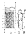
figure 1 depicts a schematic a partial view, form above, of a possible example of an installation according to the invention, -
figure 2 depicts a partial side view of the base of the installation offigure 1 , seen from the AA direction offigure 1 , -
figure 3 depicts a partial side view of the base of the installation offigure 1 , seen from the BB direction offigure 1 , -
figure 4 depicts a schematic and partial perspective view of the base of the installation offigure 1 , -
figure 5 depicts a schematic a partial view, form above, of another example of an installation according to the invention, -
figure 6 depicts a schematic and partial side view, of the base of the installation offigure 1 and taken from the CC direction offigure 1 , - The installation shown at
figure 1 comprises afuel cell 9, preferably of proton exchanging membrane type ("PEMFC"). The installation includes also adevice fuel cell 9. - The
device bundles gaseous hydrogen cylinders 8 and acommon control casing 10. Thebundles bottles 8. Thecontrol casing 10 contains a circuit for controlling the gas taken from thebundles fuel cell 9. The circuit is selectively connected at its upstream end to bothbundles cylinders 8. The circuit is selectively connected at its downstream end to thebundles cylinders 8 to thefuel cell 9 for supplying gaseous hydrogen to thefuel cell 9. - The circuit, known per se, comprises for example at least a
pressure regulator 23 and an automatic inverter organ for switching from onebundle 11 ofcylinders 8 to theother bundle 12 ofcylinders 8. - The installation is located on a
base 100. Thebase 100 includes a modular structure comprisingseveral trays trays - The base 100 comprise two
trays bundles gas cylinders 8. The twotrays bundles - The
base 100 comprises also atray 3 supporting thefuel cell 9 and a tray 4 supporting thecontrol casing 10. The fourtrays - All the trays are preferably elevated with regard to the soil via
respective legs 18. The number and design of supportinglegs 18 may vary depending on the total load distribution profile. For example each tray is supported by fourlegs 18. Preferably thelegs 18 are of self-levelling type for permitting relative height adjustments according to the soil surface configuration. - This self-levelling supporting
legs 18 structure provides more stability in terms of static and dynamic loads for different soil characteristics which vary from site to site. -
Legs 18 are also selectively detachable from thetrays trays - As shown on
figures 2 to 4 , thetrays bundles other trays 3, 4. That is to say the supporting surfaces of thebundles fuel cell 9 andcasing 10. - Preferably, the support surfaces of the bundle's
trays other trays 3, 4. That is to say thetrays bundles other trays 3, 4. - The support surfaces of
fuel cell 9tray 3 and control casing 4 tray are preferably situated in the same plan. - The different elevations permits to the forklift operator to easily distinguish among the location for
bundles fuel cell 9. This reduces also the risks of impact ofbundles rigid trays 3, 4. - For example, the
trays bundles - For example, the difference of elevation between
trays bundles other trays 3, 4 is between 5 to 20cm. - As shown on
figures 1 to 3 , thebase 100 may include separatingborders border - In addition, preferably at least one edge of a tray forming an outer border of the
base 100 comprises ashock absorbing pad 5. In particular, the outer edges of thetrays bundles 11, 12 (that is to say the edges facing forklifts and operators for handling thebundles 11, 12) comprise ashock absorbing pad 5. Theshock absorbing pad 5 is for example made from rubber or any appropriate material and may have a thickness between 2 and 10cm. This arrangement will lower damages in case of small lateral shocks with forklifts. - The modular structure of the
base 100 is preferably a bolted structure which is easily assembled at site and easily transported. The bolts of the structure might be uniquely designed so that the structure can be operated with a unique key for preventing thefts. - The elements composing of the base 100 can be made of any appropriate material of construction such as steel, composite materials, etc. able to withstand load and environmental damages.
-
Figures 5 and 6 depict another embodiment of the installation (the common elements with the embodiment offigure 1 bear the same numeral references and are not described again). - As above described, the
respective trays figure 5 , thetrays trays organs 13 such as studs. For example, the twotrays bundles more studs 13. Similarly, onetray 2 supporting abundle 11 might be attached to thetray 3 supporting the fuel cell by means of two ormore studs 13. The tray 4 supporting the control casing 10 might be attached to theother trays more studs 13. In addition, theshock absorbing pad 5 might be attached to thetrays studs 13. - The anchoring
studs 13 will provide rigidity to thebase 100 among thetrays trays - As shown at
figure 6 , adjacent trays might include respective plates 113 with concentric holes for cooperating respectively with the two ends of thestud 13. Plates might be welded in the trays. For example,studs 13 are threaded at both ends for cooperating with holes. Alternatively, one ends of thestud 13 is welded on one plate the other end of the stud being threaded for cooperating with a corresponding hole. -
Trays bundles respective trays figure 5 , several hooks 14 (for example one to four hooks) tie up each bundles 11, 12 to its platform for preventing the pulling out ofbundles bundles hooks 14 are preferably tied up with the supportingtray tray bundle - The surface of the
base 100 is based on total equipments load distribution profiles, including static and dynamic loads of the equipments. - The support surface of the trays might be designed (irregularities or coated) for providing friction to avoid free sliding of the elements supported.
- This structure can thus be deployed with either reduced soil preparation or no soil preparation and typically has no requirement for open cut foundations and piles.
- Due to its modular structure and installed with no soil preparation, the base can be deployed at any point of time in the whole year considering countries having a variety of seasons throughout the year.
- The installation and especially the base 100 are easily removable with no or reduced environmental damages for its maintenance and disposing off.
- The base is also easily transportable on one single transport and has elements that can be loaded and unloaded from a truck, deployed to the site and removed from the site by the installation team without any specific lifting devices, crane or forklift. For this reason, the unit masse of each element composing the base is preferably limited to a maximum of 100 kg.
- The base 100 structure has in addition a good stability resisting to lateral shock loads resulting from the impact of forklifts, for example when unloading the
bundles - The modular structure of the base helps to create a standardized product which optimizes the cost of manufacturing and reduces the cost of transportation. The base 100 can be transported with a fuel cell assembly on a same limited capacity truck. The structure also reduces the costs of assembling at site and the efforts in redesigning the structure based on different soil parameters and varying loads.
- Curing like methods for concrete padding are not required anymore. The base 100 can be implemented to the sites at any season of the year even during rainy seasons.
- Modifications can be done easily to the number and relative positions of the trays according to the type of installation concerned.
- For example, instead or in addition to the tray dedicated to the
control casing 10, the control casing 10 might fastened directly to at least one of theother trays - Preferably, the base 100 structure allows transferring the lateral forces of the control casing to the
trays figures 1 or5 . - Tray 4 supporting the control casing 10 can be a passive or active structure for transferring those forces.
Claims (12)
- Installation for producing and supplying electricity including a fuel cell (9), notably of proton exchanging membrane type, a device (10, 11, 12) for supplying gaseous hydrogen under pressure to the fuel cell (9), the device (10, 11, 12) for supplying gaseous hydrogen comprising at least a bundle (11, 12) of a plurality of pressurized hydrogen cylinders (8), a control casing (10), the control casing (10) containing circuit for controlling and supplying the gas taken from the bundle(s) (11, 12) of cylinders (8) to the fuel cell (9), the circuit being selectively connected to the bundle(s) (11, 12) of cylinders (8) and to the fuel cell (9) and comprising at least a pressure regulator (23), the installation being arranged on a base (100), characterized in the that the base (100) includes a modular structure comprising a first tray (1) supporting a first bundle (12) of cylinders (8), a second tray (2) supporting a second bundle (11) of cylinders (8), a third tray (3) supporting the fuel cell (9), the first (1), the second (2) and the third (3) trays being different entities put side by side and being elevated with regard to the soil via respective legs (18), first (1) and second trays (2) forming supports surface which are situated in a plan different from the plan of the third (3) tray, that is to say at a different height with regard to the soil.
- Installation according to claim 1, characterized in that the base (100) comprises a fourth tray (4) elevated with regard to the soil via respective feet (8), the fourth tray (4) supporting a control casing (10).
- Installation according to claim 2, characterized in that the support surfaces of third (3) and the fourth (4) trays are situated in a same plan above the soil.
- Installation according to any of claims 1 to 3, characterized in that the control casing (10) is fastened to at least one of: first (1), second (2) and the third (3) tray.
- Installation according to any of claims 1 to 4, characterized in that the support surface of first (1) and second (2) trays are distant of 5 to 20cm from the plans of support surfaces of the other(s) tray(s).
- Installation according to any of claims 1 to 5, characterized in that first (1) and second (2) trays are less elevated above the soil as compared to the other(s) tray(s).
- Installation according to any of claims 1 to 5, characterized in that it comprises at least a separating border (6, 7) between two adjacent trays (1, 2, 3), the separating border being elevated relative to the support surface between 2 and 10cm.
- Installation according to any of claims 1 to 7, characterized in that first tray (1) is elevated from the soil of distance comprised between 25 and 50cm.
- Installation according to any of claims 1 to 8, characterized in that at least part of the legs (18) are of self-levelling type for permitting a height adjustment according to the soil surface configuration.
- Installation according to any of claims 1 to 9, characterized in that at least part of the legs (18) are selectively detachable from the trays (1, 2, 3, 4).
- Installation according to any of claims 1 to 10, characterized in that at least one border of a tray (1, 2, 3, 4) forming an outer border of the base (100) comprise a shock absorbing pad (5), preferably made from rubber, having a thickness between 2 and 10cm.
- Installation according to any of claims 1 to 11, characterized in that the trays (1, 2, 3, 4) are attached together by attaching organs (13) that can be selectively dismantled.
Applications Claiming Priority (1)
| Application Number | Priority Date | Filing Date | Title |
|---|---|---|---|
| IN1219DE2012 IN2012DE01219A (en) | 2012-04-19 | 2012-04-19 |
Publications (1)
| Publication Number | Publication Date |
|---|---|
| EP2654117A1 true EP2654117A1 (en) | 2013-10-23 |
Family
ID=47563224
Family Applications (1)
| Application Number | Title | Priority Date | Filing Date |
|---|---|---|---|
| EP13151406.9A Withdrawn EP2654117A1 (en) | 2012-04-19 | 2013-01-16 | Installation for producing and supplying electricity including a fuel cell |
Country Status (2)
| Country | Link |
|---|---|
| EP (1) | EP2654117A1 (en) |
| IN (1) | IN2012DE01219A (en) |
Cited By (1)
| Publication number | Priority date | Publication date | Assignee | Title |
|---|---|---|---|---|
| CN109687008A (en) * | 2019-01-15 | 2019-04-26 | 安徽明天氢能科技股份有限公司 | A kind of fuel cell pile system assembles pallet |
Citations (5)
| Publication number | Priority date | Publication date | Assignee | Title |
|---|---|---|---|---|
| US20060246328A1 (en) * | 2005-05-02 | 2006-11-02 | Sprint Communications Company L.P. | Modular cell site |
| US20060244268A1 (en) * | 2002-11-15 | 2006-11-02 | Sprint Communications Company L.P. | Modular cell site with air-turbine backup |
| US20070002547A1 (en) * | 2002-03-13 | 2007-01-04 | Garmong Victor H | Shielded enclosure with extendable mast |
| US20090325018A1 (en) * | 2005-09-13 | 2009-12-31 | Patrick Sanglan | Fixed installation for supplying electric power comprising a fuel cell |
| EP2211409A1 (en) * | 2007-09-13 | 2010-07-28 | Nippon Oil Corporation | Fuel cell system |
-
2012
- 2012-04-19 IN IN1219DE2012 patent/IN2012DE01219A/en unknown
-
2013
- 2013-01-16 EP EP13151406.9A patent/EP2654117A1/en not_active Withdrawn
Patent Citations (5)
| Publication number | Priority date | Publication date | Assignee | Title |
|---|---|---|---|---|
| US20070002547A1 (en) * | 2002-03-13 | 2007-01-04 | Garmong Victor H | Shielded enclosure with extendable mast |
| US20060244268A1 (en) * | 2002-11-15 | 2006-11-02 | Sprint Communications Company L.P. | Modular cell site with air-turbine backup |
| US20060246328A1 (en) * | 2005-05-02 | 2006-11-02 | Sprint Communications Company L.P. | Modular cell site |
| US20090325018A1 (en) * | 2005-09-13 | 2009-12-31 | Patrick Sanglan | Fixed installation for supplying electric power comprising a fuel cell |
| EP2211409A1 (en) * | 2007-09-13 | 2010-07-28 | Nippon Oil Corporation | Fuel cell system |
Cited By (2)
| Publication number | Priority date | Publication date | Assignee | Title |
|---|---|---|---|---|
| CN109687008A (en) * | 2019-01-15 | 2019-04-26 | 安徽明天氢能科技股份有限公司 | A kind of fuel cell pile system assembles pallet |
| CN109687008B (en) * | 2019-01-15 | 2023-08-25 | 安徽明天氢能科技股份有限公司 | Fuel cell stack system assembly tray |
Also Published As
| Publication number | Publication date |
|---|---|
| IN2012DE01219A (en) | 2015-10-16 |
Similar Documents
| Publication | Publication Date | Title |
|---|---|---|
| AU2020451310B2 (en) | Mobile autonomous solar- wind electrical station | |
| DK1546550T3 (en) | MOBILE WIND ENERGY INSTALLATION | |
| EP2682667A2 (en) | A pressurized gas cylinders pallet | |
| EP4054956B1 (en) | Platform for stacking containers as a housing for components of an energy conversion system, and energy conversion system | |
| KR20140033200A (en) | Mobile fuel distribution station | |
| US20230282867A1 (en) | Electrochemical system and method of installing same using a skid | |
| WO2023126974A1 (en) | Portable footing based telecom tower | |
| CN202131798U (en) | Movable fast-assembling base station | |
| EP2654117A1 (en) | Installation for producing and supplying electricity including a fuel cell | |
| JP2024513579A (en) | Platform for space-saving configuration of energy conversion equipment and energy conversion equipment | |
| KR20250165272A (en) | Temporarily installable solar power generation apparatus | |
| JP2015104245A (en) | Photovoltaic power generation panel frame | |
| JP2020522979A (en) | Electric substation, installation, and mounting method | |
| JP2022040823A (en) | Carrying device, carrying device of tower-like structure and carrying/temporary placing method | |
| CN101914999A (en) | Communication device for fast integrating integrative machine room | |
| WO2019119015A1 (en) | Foundation system and method of construction | |
| US20240271451A1 (en) | A Data Centre System and Method of Construction | |
| US20240313700A1 (en) | Self-ballasted Pre-engineered Modular Platform Assembled Onsite For Generating Electricity With Bifacial Photovoltaic Modules | |
| WO2012087145A1 (en) | Method for building a site for a telecommunication device | |
| CN215802235U (en) | Steel structure frame and stack formula diesel generator platform | |
| CN202627016U (en) | Balance weight ground beam for quickly assembled communication base station | |
| CN213401476U (en) | Communication rod | |
| GB2476127A (en) | Strengthening an antenna tower | |
| JP2021143599A (en) | Tower member building-up method and lifting-up tool used for tower member building-up method | |
| US20230307168A1 (en) | Stackable components for stationary energy storage systems |
Legal Events
| Date | Code | Title | Description |
|---|---|---|---|
| PUAI | Public reference made under article 153(3) epc to a published international application that has entered the european phase |
Free format text: ORIGINAL CODE: 0009012 |
|
| AK | Designated contracting states |
Kind code of ref document: A1 Designated state(s): AL AT BE BG CH CY CZ DE DK EE ES FI FR GB GR HR HU IE IS IT LI LT LU LV MC MK MT NL NO PL PT RO RS SE SI SK SM TR |
|
| AX | Request for extension of the european patent |
Extension state: BA ME |
|
| STAA | Information on the status of an ep patent application or granted ep patent |
Free format text: STATUS: THE APPLICATION IS DEEMED TO BE WITHDRAWN |
|
| 18D | Application deemed to be withdrawn |
Effective date: 20140424 |