EP2654045A2 - X-ray telescope - Google Patents
X-ray telescope Download PDFInfo
- Publication number
- EP2654045A2 EP2654045A2 EP13161913.2A EP13161913A EP2654045A2 EP 2654045 A2 EP2654045 A2 EP 2654045A2 EP 13161913 A EP13161913 A EP 13161913A EP 2654045 A2 EP2654045 A2 EP 2654045A2
- Authority
- EP
- European Patent Office
- Prior art keywords
- monocrystalline
- strip
- parabolic
- distance
- ray
- Prior art date
- Legal status (The legal status is an assumption and is not a legal conclusion. Google has not performed a legal analysis and makes no representation as to the accuracy of the status listed.)
- Withdrawn
Links
Images
Classifications
-
- G—PHYSICS
- G21—NUCLEAR PHYSICS; NUCLEAR ENGINEERING
- G21K—HANDLING OF PARTICLES OR IONISING RADIATION NOT OTHERWISE PROVIDED FOR; IRRADIATION DEVICES; GAMMA RAY OR X-RAY MICROSCOPES
- G21K1/00—Arrangements for handling particles or ionising radiation, e.g. focusing or moderating
- G21K1/06—Arrangements for handling particles or ionising radiation, e.g. focusing or moderating using diffraction, refraction or reflection, e.g. monochromators
-
- G—PHYSICS
- G21—NUCLEAR PHYSICS; NUCLEAR ENGINEERING
- G21K—HANDLING OF PARTICLES OR IONISING RADIATION NOT OTHERWISE PROVIDED FOR; IRRADIATION DEVICES; GAMMA RAY OR X-RAY MICROSCOPES
- G21K2201/00—Arrangements for handling radiation or particles
- G21K2201/06—Arrangements for handling radiation or particles using diffractive, refractive or reflecting elements
- G21K2201/062—Arrangements for handling radiation or particles using diffractive, refractive or reflecting elements the element being a crystal
-
- G—PHYSICS
- G21—NUCLEAR PHYSICS; NUCLEAR ENGINEERING
- G21K—HANDLING OF PARTICLES OR IONISING RADIATION NOT OTHERWISE PROVIDED FOR; IRRADIATION DEVICES; GAMMA RAY OR X-RAY MICROSCOPES
- G21K2201/00—Arrangements for handling radiation or particles
- G21K2201/06—Arrangements for handling radiation or particles using diffractive, refractive or reflecting elements
- G21K2201/064—Arrangements for handling radiation or particles using diffractive, refractive or reflecting elements having a curved surface
Definitions
- Presented solution deals with an X-ray telescope for objects imaging in monochromatic X-ray radiation.
- X-ray radiation means an electromagnetic radiation with wavelengths shorter than 10 nm.
- the X-ray telescopy still uses as lenses mainly combinations of hyperboloid of revolution with paraboloid of revolution, which exploits two total reflections of rays under small angles resulting from the fact that refractive index on metals for these rays is less than one.
- Wolter telescopes There are three types of Wolter telescopes, the first two ones are various set-ups of hyperboloid and paraboloid and the third one is a combination of ellipsoid of revolution and paraboloid of revolution.
- Another principle used for construction of X-ray telescopes is the X-ray radiation collimation by a number of parallel direct channels in absorption material, through which the radiation passes, while they determine the direction, from which the incidenting radiation is detected.
- lobster's eye either one-dimensional, or two-dimensional. It works again on the principle of full reflection of the X-ray radiation from the system of thin plates bent into a parabolic strip, which reflect the radiation into a single line.
- Two-dimensional lobster's eye is a combination of two one-dimensional, mutually perpendicular systems, which reflect the radiation into a point.
- the Kirkpatrick-Baez telescope which is formed by two mutually perpendicular parabolic mirrors where the first one displays the object into a line and the other to a point. Again, due to small incidence angle, the telescope consists of many layers with common focus.
- Mutual distance between the atomic planes of given monocrystalline plate, marked with letter d, is variable in such a way that the shortest distance d 0 is at the ends located closer to the vertex line of the parabolic strip in the point x min and the longest distance d max is at the ends located farther from the vertex line of the parabolic strip in the point x max .
- the parabolic strip is formed by monocrystalline plates of monocrystal of one kind.
- the parabolic strip may consist of monocrystalline plates of at least two kinds of monocrystals. Also possible is the embodiment where between the monocrystalline plates are gaps.
- Monocrystalline plates may also be made of monocrystals, the surface of which is parallel with different atomic planes.
- the advantage of this arrangement is that it displays monochromatic X-ray radiation with wavelength ⁇ to the focal line and for displaying it can exploit maximum surface area of the parabolic strip, which means that the area, which is blind and non-reflecting, can be reduced by selection of materials in theory arbitrarily.
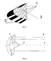
- Fig. 1 shows an example of the parabolic strip formed by bent plates of different monocrystals.
- Fig. 2 shows the vertex and focal lines and the rays coming from a distant source, which reflect themselves from any point at each monocrystalline plate to the line in focus of the parabolic strip.
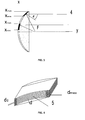
- Fig. 3 shows a section view of individual monocrystalline plates in the parabolic strip located between the coordinates x min and x max .
- Fig. 4 shows a single plate from the strip with indicated atomic planes.
- X-ray telescope is formed by thin rectangular plates with atomic planes 5 parallel with the surface of monocrystals. These plates are bent and arranged next to each other in such a way that they create parts of the parabolic strip, as shown in Fig. 1 .
- the parabolic strip is formed by two kinds of monocrystalline little plates 1 and 2 , which alternate in such a way that after each plate 1 , 2 get warmed up in various points to the temperature determined by the equation (3) defined hereinbelow, they at all points fulfill the Bragg condition for reflection of the X-ray radiation to the focal line F of the parabolic strip.
- Monocrystalline plates are fixed on their sides in two holders 3 with parallel orientation, which ensure the parabolic geometry of the strip.
- Fig. 2 shows separate X-ray rays 4 , which reflect from the monocrystalline plates of the parabolic strip to the focal line F of the parabolic strip.
- X-ray rays 4 coming from a distant object are reflected to the focal line F where constructive interference occurs.
- the strip may be composed of one kind of monocrystal, broken by spaces of gaps between them, or advantageously the strip can consist of plates of at least two kinds of monocrystals, here two kinds of monocrystalline plates 1 and 2 are described, and the gaps can be reduced or excluded, possibly combined with monocrystals with surfaces parallel with different atomic planes 5 . This will ensure that the radiation of given wavelength from a distant source is reflected to the focal line F of the parabolic strip.
- Change of distance between the atomic planes 5 in the monocrystalline plate can be created by changing the concentration of admixtures or by different thermal expansion caused by uneven heat distribution in various places of the monocrystalline plate.
- the temperatures along the strip are varied, it is possible, within limited extent, to change also the measured wavelength by changing the temperature course in different places of the monocrystalline plates and in different places along the strip.
- the distance between the planes of the monocrystalline plate is d and it is variable in such a way that the shortest distance d 0 is closer to the vertex line V of the parabolic strip and the longest distance d max is at the farther end of the monocrystalline plate from the vertex line V of the parabolic strip.
- Fig. 4 One bent monocrystalline plate in the parabolic strip with indicated atomic planes 5 and with indicated distances between separate atomic planes 5 , which vary from d 0 to d max , is shown in Fig. 4 .
- n a natural number, which determines the number of wavelengths belonging to the difference of the ray travel distances when reflecting from two neighbouring atomic planes 5
- p is double the distance of the focal line F from the vertex line V of the parabolic strip.
- d d 0 ⁇ 1 + ⁇ ⁇ ⁇ ⁇ T , where ⁇ is the thermal expansion factor of given monocrystalline plate in direction perpendicular to this monocrystalline plate and ⁇ T is the temperature difference between places on the monocrystalline plate with coordinates x and x min .
- T x T x min + 1 ⁇ ⁇ n ⁇ ⁇ 2 ⁇ p ⁇ d 0 ⁇ x 2 + p 2 - 1 , where d 0 is the distance between the neighboring atomic planes 5 at point x min , i.e. on the edge of the monocrystalline plate closer to the vertex line V of the parabolic strip.
- This X-ray telescope can be exploited in particular in the X-ray telescopy to focus the monochromatic radiation into a line segment.
Landscapes
- Physics & Mathematics (AREA)
- Spectroscopy & Molecular Physics (AREA)
- Engineering & Computer Science (AREA)
- General Engineering & Computer Science (AREA)
- High Energy & Nuclear Physics (AREA)
- Crystals, And After-Treatments Of Crystals (AREA)
- Radiation Pyrometers (AREA)
- Telescopes (AREA)
Abstract

i.e. for given monocrystalline plate (1,2) laid between (x min) and (x max) the following equation applies


Description
- Presented solution deals with an X-ray telescope for objects imaging in monochromatic X-ray radiation.
- X-ray radiation means an electromagnetic radiation with wavelengths shorter than 10 nm. Instead of optical lenses used in the visible light range, the X-ray telescopy still uses as lenses mainly combinations of hyperboloid of revolution with paraboloid of revolution, which exploits two total reflections of rays under small angles resulting from the fact that refractive index on metals for these rays is less than one.
- Since the possible incidence angles are small, from several degrees for energies 0.1 keV up to several minutes for 10 keV and for the respective wavelengths 10 nm to 0.1 nm, the lens must be assembled from multiple systems inserted one into another projecting to the same focus in order to enlarge the lens area. The higher the energy, the more systems within each other for the same area. These telescopes are called Wolter telescopes. There are three types of Wolter telescopes, the first two ones are various set-ups of hyperboloid and paraboloid and the third one is a combination of ellipsoid of revolution and paraboloid of revolution.
- Another principle used for construction of X-ray telescopes is the X-ray radiation collimation by a number of parallel direct channels in absorption material, through which the radiation passes, while they determine the direction, from which the incidenting radiation is detected.
- Another principle is so-called lobster's eye, either one-dimensional, or two-dimensional. It works again on the principle of full reflection of the X-ray radiation from the system of thin plates bent into a parabolic strip, which reflect the radiation into a single line. Two-dimensional lobster's eye is a combination of two one-dimensional, mutually perpendicular systems, which reflect the radiation into a point.
- Also known is the Kirkpatrick-Baez telescope, which is formed by two mutually perpendicular parabolic mirrors where the first one displays the object into a line and the other to a point. Again, due to small incidence angle, the telescope consists of many layers with common focus.
- All telescopes described above exploit the fact that the refractive index of some materials for the X-ray radiation is only slightly greater than one and under small angles they create total reflection. In addition, the refractive index depends on the X-ray radiation energy and for higher energies the usability is limited. All types feature relatively long focal distances.
- All examples described above cause relatively high absorption of the X-ray radiation and all systems also have relatively long focal distances, it means the image and object distances, and work for longer wavelengths - around 10 nm. Moreover, manufacture of such parts puts rather high demands for the production equipment and therefore it is costly.
- All setbacks described above are improved by an X-ray telescope using monocrystals, which displays the X-ray radiation with wavelength λ according to the presented solution. Its principle is that it is formed by a parabolic strip with the vertex line at the coordinates origin (x=0, y=0) and the focal line with coordinates (x=0, y=p/2), which is assembled from bent rectangular monocrystalline plates, cut in such a way that the atomic planes are parallel with the surface of the monocrystalline plates. These monocrystalline plates are by their edges fixed in two holders with parallel orientation, which ensure the parabolic geometry of the strip. Mutual distance between the atomic planes of given monocrystalline plate, marked with letter d, is variable in such a way that the shortest distance d0 is at the ends located closer to the vertex line of the parabolic strip in the point xmin and the longest distance dmax is at the ends located farther from the vertex line of the parabolic strip in the point xmax. Between these ends the mutual distance d of the neighboring atomic planes in each monocrystalline plate varies depending on the amount of the distance of the coordinate x from the vertex line of the parabolic strip according to equation

where n is a natural number, which determines the number of wavelengths belonging to the difference of the ray travel distances when reflecting from two neighbouring atomic planes, which is the interference condition, and p is double the distance of the focal line from the vertex line of the parabolic strip, and for the temperature course along the given monocrystalline plate in the x-axis direction in individual points corresponding to the x-coordinate the following condition is fulfilled
where γ is the thermal expansion factor of the given monocrystalline plate in direction perpendicular to its surface. - In one preferred embodiment the parabolic strip is formed by monocrystalline plates of monocrystal of one kind. In other embodiment the parabolic strip may consist of monocrystalline plates of at least two kinds of monocrystals. Also possible is the embodiment where between the monocrystalline plates are gaps.
- Monocrystalline plates may also be made of monocrystals, the surface of which is parallel with different atomic planes.
- The advantage of this arrangement is that it displays monochromatic X-ray radiation with wavelength λ to the focal line and for displaying it can exploit maximum surface area of the parabolic strip, which means that the area, which is blind and non-reflecting, can be reduced by selection of materials in theory arbitrarily.
- Schematic design of the X-ray telescope according to the presented solution is shown in attached drawings.
Fig. 1 shows an example of the parabolic strip formed by bent plates of different monocrystals.Fig. 2 shows the vertex and focal lines and the rays coming from a distant source, which reflect themselves from any point at each monocrystalline plate to the line in focus of the parabolic strip.Fig. 3 shows a section view of individual monocrystalline plates in the parabolic strip located between the coordinates xmin and xmax.Fig. 4 shows a single plate from the strip with indicated atomic planes. - Reflection of radiation under greater angle is only possible when the Bragg condition is fulfilled. According to the presented solution X-ray telescope is formed by thin rectangular plates with
atomic planes 5 parallel with the surface of monocrystals. These plates are bent and arranged next to each other in such a way that they create parts of the parabolic strip, as shown inFig. 1 . In the given example the parabolic strip is formed by two kinds of monocrystallinelittle plates plate holders 3 with parallel orientation, which ensure the parabolic geometry of the strip. -
Fig. 2 showsseparate X-ray rays 4, which reflect from the monocrystalline plates of the parabolic strip to the focal line F of the parabolic strip.X-ray rays 4 coming from a distant object are reflected to the focal line F where constructive interference occurs. Equation of parabola is defined by the equation
- In order to fulfill Bragg condition at every point it is necessary that the distance between
atomic planes 5 in each monocrystal plate along the parabolic strip changes as well. The strip may be composed of one kind of monocrystal, broken by spaces of gaps between them, or advantageously the strip can consist of plates of at least two kinds of monocrystals, here two kinds ofmonocrystalline plates atomic planes 5. This will ensure that the radiation of given wavelength from a distant source is reflected to the focal line F of the parabolic strip. Change of distance between theatomic planes 5 in the monocrystalline plate can be created by changing the concentration of admixtures or by different thermal expansion caused by uneven heat distribution in various places of the monocrystalline plate. In case the temperatures along the strip are varied, it is possible, within limited extent, to change also the measured wavelength by changing the temperature course in different places of the monocrystalline plates and in different places along the strip. The distance between the planes of the monocrystalline plate is d and it is variable in such a way that the shortest distance d 0 is closer to the vertex line V of the parabolic strip and the longest distance d max is at the farther end of the monocrystalline plate from the vertex line V of the parabolic strip. For theincidenting X-ray ray 4 forming the angle α with the normal line against the area it fulfills the Braggcondition 
where n is a natural number and λ is the wavelength of displayed X-ray radiation. - One bent monocrystalline plate in the parabolic strip with indicated
atomic planes 5 and with indicated distances between separateatomic planes 5, which vary from d 0 to d max, is shown inFig. 4 . - If the Bragg condition for a monocrystalline plate in the parabolic strip is expressed as a function of the coordinate x, the result is

where n is a natural number, which determines the number of wavelengths belonging to the difference of the ray travel distances when reflecting from two neighbouringatomic planes 5, and p is double the distance of the focal line F from the vertex line V of the parabolic strip. - When varied temperature distribution is used, the equation for thermal expansion of the distance between neighboring atomic planes is

where γ is the thermal expansion factor of given monocrystalline plate in direction perpendicular to this monocrystalline plate and ΔT is the temperature difference between places on the monocrystalline plate with coordinates x and xmin. For the course of temperature along the monocrystalline plate in direction of the x-axis at individual points with given x-coordinate the following equation must be fulfilled
where d 0 is the distance between the neighboringatomic planes 5 at point x min , i.e. on the edge of the monocrystalline plate closer to the vertex line V of the parabolic strip. - For placement and manufacture of a monocrystalline plate the following equation may be used for a plate located between the x-coordinates x min and x max

- For a plate made of germanium monocrystal and temperatures between 250 and 1000 K, for the wavelength of 0.5 nm the value is


- This X-ray telescope can be exploited in particular in the X-ray telescopy to focus the monochromatic radiation into a line segment.
Claims (5)
- X-ray telescope which displays the X-ray radiation with wavelength (λ) characterized by the fact that it is formed by a parabolic strip with the vertex line (V) at the coordinates origin (x=0, y=0) and the focal line (F) with coordinates (x=0, y=p/2), which is assembled from bent rectangular monocrystalline plates, cut in such a way that their atomic planes (5) are parallel with the surface of the monocrystalline plates, where such monocrystalline plates are by their edges fixed in two holders (3) with parallel orientation, which ensure the parabolic geometry of the strip, where the mutual distance (d) between the neighboring atomic planes (5) of given monocrystalline plate is variable in such a way that the shortest distance (do) is at the ends located closer to the vertex line (V) of the parabolic strip in the point (xmin) and the longest distance (dmax) is at the ends located farther from the vertex line (V) of the parabolic strip in the point (xmax), and between these ends the mutual distance (d) of the atomic planes (5) in each monocrystalline plate varies depending on the amount of the distance of the coordinate (x) from the vertex line (V) of the parabolic strip according to equation

where n is a natural number, which determines the number of wavelengths (λ) belonging to the difference of the ray travel distances when reflecting from two neighbouring atomic planes (5), and p is double the distance of the focal line (F) from the vertex line (V) of the parabolic strip, and for the temperature course along the given monocrystalline plate in the (x)-axis direction at individual points corresponding to the x-coordinate the following condition is fulfilled
where γ is the thermal expansion factor of the given monocrystalline plate in direction perpendicular to its surface. - X-ray telescope according to claim 1 characterized by the fact that the parabolic strip is formed by monocrystalline plates (1) of monocrystal of one kind.
- X-ray telescope according to claim 1 characterized by the fact that the parabolic strip is formed by monocrystalline plates (1,2) of at least two kinds of monocrystals.
- X-ray telescope according to any of claims 1 to 3 characterized by the fact that between the monocrystalline plates (1,2) are gaps.
- X-ray telescope according to any of claims 1 to 4 characterized by the fact that the monocrystalline plates (1,2) are made of monocrystals, the surface of which is parallel with different atomic planes (5).
Applications Claiming Priority (1)
| Application Number | Priority Date | Filing Date | Title |
|---|---|---|---|
| CZ20120265A CZ2012265A3 (en) | 2012-04-17 | 2012-04-17 | X-ray telescope |
Publications (2)
| Publication Number | Publication Date |
|---|---|
| EP2654045A2 true EP2654045A2 (en) | 2013-10-23 |
| EP2654045A3 EP2654045A3 (en) | 2017-01-25 |
Family
ID=47998317
Family Applications (1)
| Application Number | Title | Priority Date | Filing Date |
|---|---|---|---|
| EP13161913.2A Withdrawn EP2654045A3 (en) | 2012-04-17 | 2013-04-02 | X-ray telescope |
Country Status (2)
| Country | Link |
|---|---|
| EP (1) | EP2654045A3 (en) |
| CZ (1) | CZ2012265A3 (en) |
Family Cites Families (3)
| Publication number | Priority date | Publication date | Assignee | Title |
|---|---|---|---|---|
| US4084089A (en) * | 1976-12-20 | 1978-04-11 | North American Philips Corporation | Long wave-length X-ray diffraction crystal and method of manufacturing the same |
| US5923720A (en) * | 1997-06-17 | 1999-07-13 | Molecular Metrology, Inc. | Angle dispersive x-ray spectrometer |
| US6317483B1 (en) * | 1999-11-29 | 2001-11-13 | X-Ray Optical Systems, Inc. | Doubly curved optical device with graded atomic planes |
-
2012
- 2012-04-17 CZ CZ20120265A patent/CZ2012265A3/en not_active IP Right Cessation
-
2013
- 2013-04-02 EP EP13161913.2A patent/EP2654045A3/en not_active Withdrawn
Non-Patent Citations (1)
| Title |
|---|
| None |
Also Published As
| Publication number | Publication date |
|---|---|
| CZ303940B6 (en) | 2013-07-03 |
| CZ2012265A3 (en) | 2013-07-03 |
| EP2654045A3 (en) | 2017-01-25 |
Similar Documents
| Publication | Publication Date | Title |
|---|---|---|
| Maradudin et al. | Rayleigh and Wood anomalies in the diffraction of light from a perfectly conducting reflection grating | |
| EP3175280B1 (en) | Exit pupil expanding diffractive optical waveguiding device | |
| ES2803583T3 (en) | Unidirectional grating-based backlight employing a reflective island | |
| EP1642304B1 (en) | Beam conditioning system | |
| JP2020507798A (en) | Static multi-view display and method | |
| CN105865637A (en) | A spaceborne high-angle-resolution laser warning detection method and device | |
| Yeh et al. | Design and analysis of solar-tracking 2D Fresnel lens-based two staged, spectrum-splitting solar concentrators | |
| Zakirullin | An optical filter with angular selectivity of the transmittance | |
| EP3001143B1 (en) | Reflective target for surveying instruments | |
| US6863409B2 (en) | Apparatus for generating parallel beam with high flux | |
| Moon et al. | Truncated corner cubes with near-perfect retroreflection efficiency | |
| AU2015246132B2 (en) | Field inversion waveguide using micro-prism array | |
| Tetsuya et al. | Efficient light transmission, reception and beam forming in photonic crystal beam steering device in a phased array configuration | |
| Komarek et al. | Parabolic versus elliptic focusing–Optimization of the focusing design of a cold triple-axis neutron spectrometer by Monte-Carlo simulations | |
| EP2825822B1 (en) | Light duct homogenizer | |
| Juárez-Reyes et al. | Wavefronts, light rays and caustic associated with the refraction of a spherical wave by two interfaces: the axicon and the plano-convex parabolic lenses | |
| Kim et al. | Behaviors of moiré fringes induced by plate thickness | |
| CZ2012265A3 (en) | X-ray telescope | |
| EP2924421B1 (en) | X-ray diffraction imaging system with integrated supermirror | |
| CN113433621A (en) | High-efficiency grating waveguide element | |
| KR101267542B1 (en) | a hihg efficient Monochromator coated with Supermirror or reflecting wall | |
| RU2576739C2 (en) | Solar module with concentrator | |
| Chadzitaskos et al. | PROPOSAL OF NEW OPTICAL ELEMENTS | |
| US6344934B1 (en) | High dispersion, laser protection lens | |
| Jark et al. | On amplitude beam splitting of tender X-rays (2–8 keV photon energy) using conical diffraction from reflection gratings with laminar profile |
Legal Events
| Date | Code | Title | Description |
|---|---|---|---|
| PUAI | Public reference made under article 153(3) epc to a published international application that has entered the european phase |
Free format text: ORIGINAL CODE: 0009012 |
|
| 17P | Request for examination filed |
Effective date: 20130405 |
|
| AK | Designated contracting states |
Kind code of ref document: A2 Designated state(s): AL AT BE BG CH CY CZ DE DK EE ES FI FR GB GR HR HU IE IS IT LI LT LU LV MC MK MT NL NO PL PT RO RS SE SI SK SM TR |
|
| AX | Request for extension of the european patent |
Extension state: BA ME |
|
| PUAL | Search report despatched |
Free format text: ORIGINAL CODE: 0009013 |
|
| AK | Designated contracting states |
Kind code of ref document: A3 Designated state(s): AL AT BE BG CH CY CZ DE DK EE ES FI FR GB GR HR HU IE IS IT LI LT LU LV MC MK MT NL NO PL PT RO RS SE SI SK SM TR |
|
| AX | Request for extension of the european patent |
Extension state: BA ME |
|
| RIC1 | Information provided on ipc code assigned before grant |
Ipc: G21K 1/06 20060101AFI20161219BHEP |
|
| STAA | Information on the status of an ep patent application or granted ep patent |
Free format text: STATUS: THE APPLICATION IS DEEMED TO BE WITHDRAWN |
|
| 18D | Application deemed to be withdrawn |
Effective date: 20170726 |