EP2654042A1 - Structure for supporting nuclear reactor vessel and method for building structure for supporting nuclear reactor vessel - Google Patents
Structure for supporting nuclear reactor vessel and method for building structure for supporting nuclear reactor vessel Download PDFInfo
- Publication number
- EP2654042A1 EP2654042A1 EP11849465.7A EP11849465A EP2654042A1 EP 2654042 A1 EP2654042 A1 EP 2654042A1 EP 11849465 A EP11849465 A EP 11849465A EP 2654042 A1 EP2654042 A1 EP 2654042A1
- Authority
- EP
- European Patent Office
- Prior art keywords
- tube
- shaped steel
- steel plate
- plate
- shaped
- Prior art date
- Legal status (The legal status is an assumption and is not a legal conclusion. Google has not performed a legal analysis and makes no representation as to the accuracy of the status listed.)
- Withdrawn
Links
- 238000000034 method Methods 0.000 title claims description 14
- 229910000831 Steel Inorganic materials 0.000 claims abstract description 184
- 239000010959 steel Substances 0.000 claims abstract description 184
- 230000002093 peripheral effect Effects 0.000 claims abstract description 110
- 239000000945 filler Substances 0.000 claims description 12
- 238000010276 construction Methods 0.000 claims description 4
- 238000010008 shearing Methods 0.000 description 11
- 238000003466 welding Methods 0.000 description 10
- 230000000694 effects Effects 0.000 description 7
- 238000005452 bending Methods 0.000 description 5
- 239000011440 grout Substances 0.000 description 2
- 230000000149 penetrating effect Effects 0.000 description 2
- 239000000463 material Substances 0.000 description 1
Images



Classifications
-
- G—PHYSICS
- G21—NUCLEAR PHYSICS; NUCLEAR ENGINEERING
- G21C—NUCLEAR REACTORS
- G21C13/00—Pressure vessels; Containment vessels; Containment in general
- G21C13/02—Details
- G21C13/024—Supporting constructions for pressure vessels or containment vessels
-
- E—FIXED CONSTRUCTIONS
- E04—BUILDING
- E04B—GENERAL BUILDING CONSTRUCTIONS; WALLS, e.g. PARTITIONS; ROOFS; FLOORS; CEILINGS; INSULATION OR OTHER PROTECTION OF BUILDINGS
- E04B1/00—Constructions in general; Structures which are not restricted either to walls, e.g. partitions, or floors or ceilings or roofs
- E04B1/16—Structures made from masses, e.g. of concrete, cast or similarly formed in situ with or without making use of additional elements, such as permanent forms, substructures to be coated with load-bearing material
-
- F—MECHANICAL ENGINEERING; LIGHTING; HEATING; WEAPONS; BLASTING
- F22—STEAM GENERATION
- F22B—METHODS OF STEAM GENERATION; STEAM BOILERS
- F22B37/00—Component parts or details of steam boilers
- F22B37/02—Component parts or details of steam boilers applicable to more than one kind or type of steam boiler
- F22B37/24—Supporting, suspending or setting arrangements, e.g. heat shielding
- F22B37/246—Supporting, suspending or setting arrangements, e.g. heat shielding for steam generators of the reservoir type, e.g. nuclear steam generators
- F22B37/248—Supporting, suspending or setting arrangements, e.g. heat shielding for steam generators of the reservoir type, e.g. nuclear steam generators with a vertical cylindrical wall
-
- Y—GENERAL TAGGING OF NEW TECHNOLOGICAL DEVELOPMENTS; GENERAL TAGGING OF CROSS-SECTIONAL TECHNOLOGIES SPANNING OVER SEVERAL SECTIONS OF THE IPC; TECHNICAL SUBJECTS COVERED BY FORMER USPC CROSS-REFERENCE ART COLLECTIONS [XRACs] AND DIGESTS
- Y02—TECHNOLOGIES OR APPLICATIONS FOR MITIGATION OR ADAPTATION AGAINST CLIMATE CHANGE
- Y02E—REDUCTION OF GREENHOUSE GAS [GHG] EMISSIONS, RELATED TO ENERGY GENERATION, TRANSMISSION OR DISTRIBUTION
- Y02E30/00—Energy generation of nuclear origin
- Y02E30/30—Nuclear fission reactors
Definitions
- the present invention relates to a nuclear reactor vessel support structure for supporting a nuclear reactor vessel in an annular structure having the nuclear reactor vessel housed therein and a construction method of the nuclear reactor vessel support structure.
- a nuclear reactor vessel is housed in a nuclear reactor building in a state in which the nuclear reactor vessel is supported by a structure of a nuclear reactor building (for example, see Patent Literature 1).
- a member (a support) affixed to the structure is mounted in a nuclear reactor vessel and the support is affixed to the structure so as to be supported by the structure.
- the support needs to be securely affixed to the structure and integrally formed with the structure so that the support is not deformed due to a vertical load or a horizontal load during an earthquake. Therefore, the support is affixed to the structure by welding when affixing to the structure.
- Patent Literature 1 Japanese Unexamined Patent Application, First Publication No. 2007-85814
- a nuclear reactor vessel support structure capable of preventing a support and a structure (a tube-shaped structure) from being deformed at a bonded portion thereof.
- a nuclear reactor vessel support structure includes: an inner peripheral tube-shaped steel plate, an outer peripheral tube-shaped steel plate, and an intermediate tube-shaped steel plate disposed between the inner peripheral and outer peripheral tube-shaped steel plates. Further, the nuclear reactor vessel support structure is a structure which supports a nuclear reactor vessel on the inner peripheral side of a tube-shaped structure formed by pouring concrete between the inner peripheral steel plate and the intermediate tube-shaped steel plate and between the intermediate tube-shaped steel plate and the outer peripheral tube-shaped steel plate.
- the nuclear reactor vessel support structure includes a support which has a tube-shaped plate disposed on the inner peripheral side of the intermediate tube-shaped steel plate, and an annular plate which protrudes to the inner peripheral side of the tube-shaped plate and to which a connection part connected to the nuclear reactor vessel is affixed. Further, the support may be affixed to the concrete placed between the inner peripheral tube-shaped steel plate and the intermediate tube-shaped steel plate by a first bar member extending in a vertical direction and affixed to the inner peripheral tube-shaped steel plate or the intermediate tube-shaped steel plate by a second bar member extending in a radial direction of the tube-shaped structure.
- a construction method of the above nuclear reactor vessel support structure includes: a tube-shaped steel plate installing process of installing an inner peripheral tube-shaped steel plate, an outer peripheral tube-shaped steel plate, and an intermediate tube-shaped steel plate; a first concrete pouring process of pouring concrete in a position between the inner peripheral tube-shaped steel plate and the intermediate tube-shaped steel plate and between the outer peripheral tube-shaped steel plate and the intermediate tube-shaped steel plate, to a lower height than a position at which a support, a first bar member and a second bar member are installed; a support installing process of installing the support along with the first bar member and affixing the support to the inner peripheral tube-shaped steel or the intermediate tube-shaped steel plate by the second bar member; and a second concrete pouring process of pouring concrete in a position at which the support, the first bar member, and the second bar member are installed.
- the support may be affixed to the concrete placed between the inner peripheral tube-shaped steel plate and the intermediate tube-shaped steel plate by the first bar member extending in a vertical direction and affixed to the inner peripheral tube-shaped steel plate or the intermediate tube-shaped steel plate by the second bar member extending in a radial direction of the tube-shaped structure.
- the support can resist an out-of-plane bending load, that is, a vertical load applied thereto with the first bar member against a load during an earthquake.
- the support can resist a shearing load, that is, a horizontal load applied thereto with the second bar member. Therefore, the support and the tube-shaped structure can be securely affixed to each other.
- the support and the tube-shaped structure can be affixed to each other without welding, and thereby the thermal distortion (deformation) does not occur. As a result, it is possible to prevent the support and the tube-shaped structure from being deformed at the bonded portion thereof.
- the first bar member may be a foundation bolt of which a lower end side is buried in the concrete placed between the inner peripheral tube-shaped steel plate and the intermediate tube-shaped steel plate and an upper end side is inserted into a through hole formed in the annular plate to affix the annular plate.
- the annular plate can be affixed to the concrete placed between the inner peripheral tube-shaped steel plate and the intermediate tube-shaped steel plate by the foundation bolt.
- the first bar member may be a first stud which is bonded to a lower surface of the annular plate and buried in the concrete placed between the inner peripheral tube-shaped steel plate and the intermediate tube-shaped steel plate.
- the annular plate can be affixed to the concrete placed between the inner peripheral tube-shaped steel plate and the intermediate tube-shaped steel plate by the first stud.
- the plurality of first studs may be evenly installed on the lower surface of the annular plate. Therefore, the load applied to the annular plate can be dispersed throughout the concrete placed between the inner peripheral tube-shaped steel plate and the intermediate tube-shaped steel plate through the first stud.
- the second bar member has a radial outer end side inserted into the through hole formed in the intermediate tube-shaped steel plate and buried in the concrete placed between the intermediate tube-shaped steel plate and the outer peripheral tube-shaped steel plate.
- the second bar member is an anchor bolt which has a radial inner end side inserted into the through hole formed in the tube-shaped plate and affixes the tube-shaped plate.
- a filler may be filled between the intermediate tube-shaped steel plate and the tube-shaped plate.
- the tube-shaped plate can be affixed to the intermediate tube-shaped steel plate by the anchor bolt.
- the filler for example, a grout material, a shim, and the like, may be filled between the tube-shaped plate and the intermediate tube-shaped steel plate to easily adjust the radial position of the support.
- the intermediate tube-shaped steel plate is divided vertically into two portions disposed above and below the tube-shaped plate.
- a splice plate is disposed over the tube-shaped plate and the intermediate tube-shaped steel plate.
- the second bar member may be a bolt which connects the tube-shaped plate with the splice plate and a bolt which joins the divided body to the splice plate.
- the tube-shaped plate can be affixed to the intermediate tube-shaped steel plate through the splice plate by the bolts.
- a shim may be disposed between the splice plate and the tube-shaped plate or the intermediate tube-shaped steel plate to adjust an interval between the splice plate and the tube-shaped plate or the intermediate tube-shaped steel plate.
- a second stud buried in the concrete placed between the inner tube-shaped steel plate and the intermediate tube-shaped steel plate may be bonded to the outer peripheral surface of the tube-shaped plate.
- the tube-shaped plate can be affixed to the concrete between the intermediate tube-shaped steel plate and the outer tube-shaped steel plate by the second stud and can resist the shearing load along with the bolt.
- the plurality of second studs is evenly bonded to the outer peripheral surface of the tube-shaped plate. Therefore, the shearing load applied to the tube-shaped plate can be dispersed throughout the concrete between the intermediate tube-shaped steel plate and the outer tube-shaped steel plate.
- the support includes a tube-shaped body that protrudes downward from the inner peripheral side of the annular plate and is disposed on the upper portion of the inner peripheral tube-shaped steel plate, and a splice plate is disposed over the tube-shaped body and the inner peripheral tube-shaped steel plate.
- the second bar member is a bolt which connects a second tube-shaped plate with the splice plate and a bolt which joins the inner peripheral tube-shaped steel plate and the splice plate.
- the filler may be filled between the tube-shaped plate and the intermediate tube-shaped steel plate.
- the second bar member may be the aforementioned bolt, and an anchor bolt which has the radial outer end side inserted into the through hole formed in the intermediate tube-shaped steel plate and buried in the concrete placed between the intermediate tube-shaped steel plate and the outer peripheral tube-shaped steel plate and the radial inner end side inserted into the through hole formed in the tube-shaped plate to affix the tube-shaped plate.
- the support can be affixed to the intermediate tube-shaped steel plate by the anchor bolt and can resist the shearing load applied thereto along with the bolt.
- a rib protruding downward may be formed on the lower surface of the annular plate. According to the foregoing configuration, the support can resist the shearing load applied thereto with the rib.
- the support is affixed to the concrete placed between the inner peripheral tube-shaped steel plate and the intermediate tube-shaped steel plate by the first bar member extending in a vertical direction and affixed to the inner peripheral tube-shaped steel plate or the intermediate tube-shaped steel plate by the second bar member extending in a radial direction of the tube-shaped structure. Therefore, the support can resist the out-of-plane bending load applied thereto with the first bar member, and the support can resist the shearing load applied thereto with the second bar member. Further, the support can be bonded to the tube-shaped structure without welding. Therefore, it is possible to prevent the thermal distortion (deformation) due to the welding and to prevent the support and the tube-shaped structure from being deformed at the bonded portion thereof.
- a nuclear reactor vessel support structure 1 is configured to support a nuclear reactor vessel 3 at an inner peripheral side of a tube-shaped structure 2 which is a structure of a nuclear reactor building.
- the tube-shaped structure 2 includes an inner peripheral tube-shaped steel plate 4 of a cylindrical shape extending in a vertical direction, an outer peripheral tube-shaped steel plate 6, and an intermediate tube-shaped steel plate 5 disposed between the inner and outer peripheral tube-shaped steel plates.
- an inner peripheral side concrete C1 is placed between the inner peripheral tube-shaped steel plate 4 and the intermediate tube-shaped steel plate 5 and an outer peripheral side concrete C2 is placed between the intermediate tube-shaped steel plate 5 and the outer peripheral tube-shaped steel plate 6.
- the inner peripheral tube-shaped steel plate 4 is formed to have a height lower than those of the intermediate tube-shaped steel plate 5 and the outer peripheral tube-shaped steel plate 6.
- the nuclear reactor vessel support structure 1 includes a support 14 having a cylindrical tube-shaped plate 12 which is disposed on the inner peripheral side of the intermediate tube-shaped steel plate 5, and a cylindrical annular plate 13 to which a radial support (a connection part) 7 is affixed, which protrudes to the inner peripheral side of the cylindrical tube-shaped plate 12 and is connected to the nuclear reactor vessel 3.
- the radial support 7 includes a plurality of radial support keys 7a which are disposed around the nuclear reactor vessel 3 in a circumferential direction. Further, the plurality of radial support keys 7a are connected with each other and alternately affixed to the nuclear reactor vessel 3 and the annular plate 13.
- the annular plate 13 of the support 14 is affixed to the inner peripheral side concrete C1 by foundation bolts (first bar members) 15 extending in a vertical direction.
- the tube-shaped plate 12 of the support 14 is affixed to the intermediate tube-shaped steel plate 5 by anchor bolts (second bar members) 16 extending in a radial direction of the tube-shaped structure 2.
- the annular plate 13 is disposed above the inner peripheral tube-shaped steel plate 4 and a lower surface 13a thereof abuts a surface of the inner peripheral side concrete C1. Further, the annular plate 13 is provided with a plurality of through holes 13c that have the foundation bolts 15 penetrating therethrough in a vertical direction so as to be inserted thereinto and are disposed at a predetermined interval in a circumferential direction. A plurality of ribs 17 protruding downward are formed on a lower surface 13a of the annular plate 13. The plurality of ribs 17 are steel plates having a substantially triangular shape and are disposed at a predetermined interval in a circumferential direction of the annular plate 13.
- the foundation bolt 15 is installed to have a lower end 15a side buried in the inner peripheral side concrete C1 and an upper end 15b side protruding upward from the inner peripheral side concrete C1. Further, the plurality of foundation bolts 15 is disposed at a predetermined interval in the circumferential direction of the tube-shaped structure 2. In addition, the upper end 15b sides of the foundation bolts 15 are inserted into the through holes 13c of the annular plate 13 and the foundation bolts 15 are screwed with nuts 15c such that the annular plate 13 is affixed to the inner peripheral side concrete.
- the tube-shaped plate 12 is provided with a plurality of through holes 12c that have the anchor bolts 16 penetrating therethrough in a radial direction so as to be inserted thereinto and are disposed at a predetermined interval in a circumferential direction.
- the anchor bolt 16 is installed to have a radial outer end 16a side buried in the outer peripheral side concrete C2 and a radial inner end 16b side protruding to the inner side of the intermediate tube-shaped steel plate 5. Meanwhile, through holes 5c into which the anchor bolts 16 are inserted are formed in the intermediate tube-shaped steel plate 5. Further, the plurality of anchor bolts 16 is disposed at a predetermined interval in a circumferential direction and a vertical direction.
- the anchor bolts 16 are mounted to have the radial inner end 16b sides inserted into the through holes 12c of the tube-shaped plate 12 and are screwed with the nuts 16c such that the tube-shaped plate 12 is affixed to the outer peripheral side concrete.
- a filler 18, such as a grout, a shim, and the like, is filled between the tube-shaped plate 12 and the intermediate tube-shaped steel plate 5. The filler 18 is disposed to adjust the radial position of the support 14 by adjusting the interval between the tube-shaped plate 12 and the intermediate tube-shaped steel plate 5.
- the inner peripheral tube-shaped steel plate 4, the intermediate tube-shaped steel plate 5, and the outer peripheral tube-shaped steel plate 6 are installed at a predetermined interval from one another in a radial direction.
- the concrete is poured between the inner peripheral tube-shaped steel plate 4 and the intermediate tube-shaped steel plate 5 and between the intermediate tube-shaped steel plate 5 and the outer peripheral tube-shaped steel plate 6 to a lower height than a position at which the support 14, the foundation bolts 15, and the anchor bolts 16 are installed.
- the support 14 is installed at a predetermined position along with the foundation bolts 15 and the anchor bolt 16 to adjust the position. In this case, the support 14 is temporarily fastened if necessary.
- the concrete is poured between the inner peripheral tube-shaped steel plate 4 and the intermediate tube-shaped steel plate 5 and between the intermediate tube-shaped steel plate 5 and the outer peripheral tube-shaped steel plate 6, and the foundation bolts 15 and the anchor bolts 16 are buried in the concrete.
- the filler 18 is filled between the tube-shaped plate 12 and the intermediate tube-shaped steel plate 5 to adjust the radial position of the support 14.
- the support 14 is affixed to the tube-shaped structure 2 by the foregoing method.
- the support 14 is affixed to the inner peripheral side concrete C1 by the foundation bolts 15 and is affixed to the inner peripheral side tube-shaped steel plate 4 by the anchor bolts 16. Therefore, the support 14 can resist the out-of-plane bending load applied thereto with the foundation bolts 15 and the support 14 can resist the shearing load applied thereto with the anchor bolts 16. Further, the support 14 and the tube-shaped structure 2 can be integrated without welding. Therefore, it is possible to prevent thermal distortion (deformation) due to welding and to prevent the support 14 and the tube-shaped structure 2 from being deformed at the bonded portion thereof.
- the radial position of the support 14 for the tube-shaped structure 2 can be adjusted by the filler 18 filled between the tube-shaped plate 12 and the intermediate tube-shaped steel plate 5. Further, the support 14 can resist the shearing load applied thereto with the rib 17 formed on the lower surface 13a of the annular plate 13.
- a nuclear reactor vessel support structure 21 includes a plurality of studs (first studs, first bar members) 22 which are installed on the lower surface 13a of the annular plate 13, instead of the foundation bolt 15 (see Fig. 3 ) in the first embodiment.
- the studs 22 are installed on the whole lower surface of the annular plate 13. The studs 22 may be attached when the support 14 is manufactured in advance. Therefore, a work load on site may be reduced.
- the support 14 can resist the out-of-plane bending load applied thereto with the studs 22. Therefore, the same effect as the first embodiment can be obtained. Further, the studs 22 are evenly installed on the whole lower surface 13a of the annular plate 13. Therefore, the load applied to the annular plate 13 can be dispersed throughout the inner peripheral side concrete C1.
- a nuclear reactor vessel support structure 31 includes high strength bolts (second bar members) 33 that bond the tube-shaped plate 12 to the intermediate tube-shaped steel plate 5 through a splice plate 32, instead of the anchor bolts 16 (see Fig. 3 ) according to the first embodiment.
- the intermediate tube-shaped steel plate 5 is divided in a vertical direction and the tube-shaped plate 12 is disposed between the intermediate tube-shaped steel plates 5 which are divided vertically.
- the splice plate 32 is disposed over both the tube-shaped plate 12 and the intermediate tube-shaped steel plate 5.
- the tube-shaped plate 12 and the splice plate 32 are affixed to each other by the high strength bolts 33, and the intermediate tube-shaped steel plate 5 and the splice plate 32 are affixed to each other by the high strength bolts 33.
- the tube-shaped plate 12 is formed of a thicker steel plate than the intermediate tube-shaped steel plate 5. Therefore, a shim 34 for adjusting the thickness is installed between the intermediate tube-shaped steel plate 5 and the splice plate 32. Additionally, when the tube-shaped plate 12 is a thinner steel plate than the intermediate tube-shaped steel plate 5, the shim 34 may be installed between the tube-shaped plate 12 and the splice plate 32.
- a stud (second stud) 35 has one end bonded to the outer peripheral side of the tube-shaped plate 12 and the other end buried in the outer peripheral side concrete C2.
- the tube-shaped plate 12 and the intermediate tube-shaped steel plate 5 can be integrated through the splice plate 32 by the high strength bolts 33. Therefore, the same effect as the first embodiment is obtained.
- the stud 35 has one end bonded to the outer peripheral side of the tube-shaped plate 12 and the other end buried in the outer peripheral side concrete C2. Therefore, the support 14 can resist the shearing load applied thereto with the stud. Further, the position of the support 14 for the tube-shaped structure 2 can be adjusted by adjusting the thickness of the shim 34.
- a nuclear reactor vessel support structure 41 according to a fourth embodiment includes the studs (first studs, first bar members) 22 which are installed on the lower surface 13a of the annular plate 13 as in the second embodiment, instead of the foundation bolt 15 (see Fig. 4 ) according to the third embodiment.
- the same effect as the third embodiment is obtained.
- a nuclear reactor vessel support structure 51 includes a tube-shaped body 52 which is bonded to the inner peripheral side of the annular plate 13 so as to protrude downward therefrom. Further, the tube-shaped body 52 is disposed on the upper portion of the inner peripheral tube-shaped steel plate 4 and is bonded to the inner peripheral tube-shaped steel plate 4 through a splice plate 53 disposed over the second tube-shaped plate 52 and the inner peripheral side tube-shaped steel 4 by high strength bolts (second bar members) 54. Additionally, in Fig.
- the splice plate 53 is disposed at both the second tube-shaped plate 52 and the inner peripheral tube-shaped steel plate 4, but may be disposed at one side thereof (the side on which nuts are fastened).
- the second tube-shaped plate 52 is welded to the annular plate 13 in advance by, for example, welding, and the like.
- the tube-shaped plate 12 is disposed on the inner peripheral side of the intermediate tube-shaped steel plate 5 and the filler 18 is filled between the tube-shaped plate 12 and the intermediate tube-shaped steel plate 5. The radial position of the support 14 is adjusted by the filler 18.
- the second tube-shaped plate 52 is affixed to the inner peripheral tube-shaped steel plate 4 by the high strength bolts 54 and the support 14 can resist the shearing load applied thereto with the high strength bolts 54. Therefore, the same effect as the first embodiment is obtained.
- a nuclear reactor vessel support structure 61 according to the sixth embodiment includes the studs (first studs, first bar members) 22 which are installed on the lower surface 13a of the annular plate 13 as in the second embodiment, instead of the foundation bolt 15 (see Fig. 7 ) according to the fifth embodiment. According to a nuclear reactor vessel support structure 61 according to the sixth embodiment, the same effect as the fifth embodiment is obtained.
- the rib 17 is formed on the lower surface 13a of the annular plate 13.
- a configuration that does not include the rib 17 may be allowed.
- the tube-shaped plate 12 is not affixed to the intermediate tube-shaped steel plate 5.
- the tube-shaped plate 12 may be affixed to the intermediate tube-shaped steel plate 5 by the anchor bolts 16.
- the high strength bolts 33 and 54 are used.
- bolts other than the high strength bolts 33 and 54 may be used.
- the rib 17 is configured of the steel plate having a substantially triangular shape. However, the rib may be formed in other shapes.
- the support is affixed to the concrete placed between the inner peripheral tube-shaped steel plate and the intermediate tube-shaped steel plate by the first bar member extending in a vertical direction.
- the support is affixed to the inner peripheral tube-shaped steel plate or the intermediate tube-shaped steel plate by the second bar member extending in a radial direction of the tube-shaped structure. Therefore, the support can resist the out-of-plane bending load applied thereto with the first bar member. Further, the support can resist the shearing load applied thereto with the second bar member.
- the support can be bonded to the tube-shaped structure without the welding. Thermal distortion (deformation) due to welding does not occur. Therefore, it is possible to prevent the support and the tube-shaped structure from being deformed at the bonded portion thereof.
Landscapes
- Engineering & Computer Science (AREA)
- Physics & Mathematics (AREA)
- General Engineering & Computer Science (AREA)
- Architecture (AREA)
- Plasma & Fusion (AREA)
- High Energy & Nuclear Physics (AREA)
- Mechanical Engineering (AREA)
- Thermal Sciences (AREA)
- Electromagnetism (AREA)
- Civil Engineering (AREA)
- Structural Engineering (AREA)
- Buildings Adapted To Withstand Abnormal External Influences (AREA)
- Foundations (AREA)
Abstract
Description
- The present invention relates to a nuclear reactor vessel support structure for supporting a nuclear reactor vessel in an annular structure having the nuclear reactor vessel housed therein and a construction method of the nuclear reactor vessel support structure.
Priority is claimed on Japanese Patent Application No.2010-277203 filed on December 13, 2010 - Conventionally, a nuclear reactor vessel is housed in a nuclear reactor building in a state in which the nuclear reactor vessel is supported by a structure of a nuclear reactor building (for example, see Patent Literature 1).
For example, a member (a support) affixed to the structure is mounted in a nuclear reactor vessel and the support is affixed to the structure so as to be supported by the structure.
In addition, the support needs to be securely affixed to the structure and integrally formed with the structure so that the support is not deformed due to a vertical load or a horizontal load during an earthquake. Therefore, the support is affixed to the structure by welding when affixing to the structure. - [Patent Literature 1] Japanese Unexamined Patent Application, First Publication No.
2007-85814 - However, when the support is welded to the structure, thermal distortion (deformation) occurs at the bonded portion due to the welding. As a result, there is a problem in that the nuclear reactor vessel may not be installed in the structure with high precision.
- In consideration of the above-mentioned circumstances, it is an object of the present invention to provide a nuclear reactor vessel support structure capable of preventing a support and a structure (a tube-shaped structure) from being deformed at a bonded portion thereof.
- In order to achieve the foregoing object, according to an aspect of the present invention, a nuclear reactor vessel support structure includes: an inner peripheral tube-shaped steel plate, an outer peripheral tube-shaped steel plate, and an intermediate tube-shaped steel plate disposed between the inner peripheral and outer peripheral tube-shaped steel plates. Further, the nuclear reactor vessel support structure is a structure which supports a nuclear reactor vessel on the inner peripheral side of a tube-shaped structure formed by pouring concrete between the inner peripheral steel plate and the intermediate tube-shaped steel plate and between the intermediate tube-shaped steel plate and the outer peripheral tube-shaped steel plate. The nuclear reactor vessel support structure includes a support which has a tube-shaped plate disposed on the inner peripheral side of the intermediate tube-shaped steel plate, and an annular plate which protrudes to the inner peripheral side of the tube-shaped plate and to which a connection part connected to the nuclear reactor vessel is affixed. Further, the support may be affixed to the concrete placed between the inner peripheral tube-shaped steel plate and the intermediate tube-shaped steel plate by a first bar member extending in a vertical direction and affixed to the inner peripheral tube-shaped steel plate or the intermediate tube-shaped steel plate by a second bar member extending in a radial direction of the tube-shaped structure.
- According to another aspect of the present invention, a construction method of the above nuclear reactor vessel support structure includes: a tube-shaped steel plate installing process of installing an inner peripheral tube-shaped steel plate, an outer peripheral tube-shaped steel plate, and an intermediate tube-shaped steel plate; a first concrete pouring process of pouring concrete in a position between the inner peripheral tube-shaped steel plate and the intermediate tube-shaped steel plate and between the outer peripheral tube-shaped steel plate and the intermediate tube-shaped steel plate, to a lower height than a position at which a support, a first bar member and a second bar member are installed; a support installing process of installing the support along with the first bar member and affixing the support to the inner peripheral tube-shaped steel or the intermediate tube-shaped steel plate by the second bar member; and a second concrete pouring process of pouring concrete in a position at which the support, the first bar member, and the second bar member are installed.
- According to the aspects of the present invention, the support may be affixed to the concrete placed between the inner peripheral tube-shaped steel plate and the intermediate tube-shaped steel plate by the first bar member extending in a vertical direction and affixed to the inner peripheral tube-shaped steel plate or the intermediate tube-shaped steel plate by the second bar member extending in a radial direction of the tube-shaped structure. Thereby, the support can resist an out-of-plane bending load, that is, a vertical load applied thereto with the first bar member against a load during an earthquake. Further, the support can resist a shearing load, that is, a horizontal load applied thereto with the second bar member. Therefore, the support and the tube-shaped structure can be securely affixed to each other.
The support and the tube-shaped structure can be affixed to each other without welding, and thereby the thermal distortion (deformation) does not occur. As a result, it is possible to prevent the support and the tube-shaped structure from being deformed at the bonded portion thereof. - Further, in the nuclear reactor vessel structure according to the aspects of the present invention, the first bar member may be a foundation bolt of which a lower end side is buried in the concrete placed between the inner peripheral tube-shaped steel plate and the intermediate tube-shaped steel plate and an upper end side is inserted into a through hole formed in the annular plate to affix the annular plate.
According to the foregoing configuration, the annular plate can be affixed to the concrete placed between the inner peripheral tube-shaped steel plate and the intermediate tube-shaped steel plate by the foundation bolt. - Further, in the nuclear reactor vessel support structure according to the aspects of the present invention, the first bar member may be a first stud which is bonded to a lower surface of the annular plate and buried in the concrete placed between the inner peripheral tube-shaped steel plate and the intermediate tube-shaped steel plate.
According to the foregoing configuration, the annular plate can be affixed to the concrete placed between the inner peripheral tube-shaped steel plate and the intermediate tube-shaped steel plate by the first stud. Further, the plurality of first studs may be evenly installed on the lower surface of the annular plate. Therefore, the load applied to the annular plate can be dispersed throughout the concrete placed between the inner peripheral tube-shaped steel plate and the intermediate tube-shaped steel plate through the first stud. - Further, in the nuclear reactor vessel support structure according to the aspects of the present invention, the second bar member has a radial outer end side inserted into the through hole formed in the intermediate tube-shaped steel plate and buried in the concrete placed between the intermediate tube-shaped steel plate and the outer peripheral tube-shaped steel plate. In addition, the second bar member is an anchor bolt which has a radial inner end side inserted into the through hole formed in the tube-shaped plate and affixes the tube-shaped plate. A filler may be filled between the intermediate tube-shaped steel plate and the tube-shaped plate.
According to the foregoing configuration, the tube-shaped plate can be affixed to the intermediate tube-shaped steel plate by the anchor bolt. The filler, for example, a grout material, a shim, and the like, may be filled between the tube-shaped plate and the intermediate tube-shaped steel plate to easily adjust the radial position of the support. - Further, in the nuclear reactor vessel support structure according to the aspects of the present invention, the intermediate tube-shaped steel plate is divided vertically into two portions disposed above and below the tube-shaped plate. In addition, a splice plate is disposed over the tube-shaped plate and the intermediate tube-shaped steel plate. The second bar member may be a bolt which connects the tube-shaped plate with the splice plate and a bolt which joins the divided body to the splice plate.
According to the foregoing configuration, the tube-shaped plate can be affixed to the intermediate tube-shaped steel plate through the splice plate by the bolts. - Further, in the nuclear reactor vessel support structure according to the aspects of the present invention, a shim may be disposed between the splice plate and the tube-shaped plate or the intermediate tube-shaped steel plate to adjust an interval between the splice plate and the tube-shaped plate or the intermediate tube-shaped steel plate.
According to the foregoing configuration, even when the thickness of the tube-shaped plate is different from that of the intermediate tube-shaped steel, the tube-shaped plate can be securely affixed to the intermediate tube-shaped steel plate and the thickness of the shim can be adjusted to easily adjust the radial position of the support. - In the nuclear reactor vessel support structure according to the aspects of the present invention, a second stud buried in the concrete placed between the inner tube-shaped steel plate and the intermediate tube-shaped steel plate may be bonded to the outer peripheral surface of the tube-shaped plate.
According to the foregoing configuration, the tube-shaped plate can be affixed to the concrete between the intermediate tube-shaped steel plate and the outer tube-shaped steel plate by the second stud and can resist the shearing load along with the bolt. In addition, the plurality of second studs is evenly bonded to the outer peripheral surface of the tube-shaped plate. Therefore, the shearing load applied to the tube-shaped plate can be dispersed throughout the concrete between the intermediate tube-shaped steel plate and the outer tube-shaped steel plate. - Further, in the nuclear reactor vessel support structure according to the aspects of the present invention, the support includes a tube-shaped body that protrudes downward from the inner peripheral side of the annular plate and is disposed on the upper portion of the inner peripheral tube-shaped steel plate, and a splice plate is disposed over the tube-shaped body and the inner peripheral tube-shaped steel plate. The second bar member is a bolt which connects a second tube-shaped plate with the splice plate and a bolt which joins the inner peripheral tube-shaped steel plate and the splice plate. The filler may be filled between the tube-shaped plate and the intermediate tube-shaped steel plate.
According to the foregoing configuration, the support can be affixed to the inner peripheral tube-shaped steel plate through the tube-shaped body and the splice plate by the bolts. - Further, in the nuclear reactor vessel support structure according to the aspects of the present invention, the second bar member may be the aforementioned bolt, and an anchor bolt which has the radial outer end side inserted into the through hole formed in the intermediate tube-shaped steel plate and buried in the concrete placed between the intermediate tube-shaped steel plate and the outer peripheral tube-shaped steel plate and the radial inner end side inserted into the through hole formed in the tube-shaped plate to affix the tube-shaped plate.
According to the foregoing configuration, the support can be affixed to the intermediate tube-shaped steel plate by the anchor bolt and can resist the shearing load applied thereto along with the bolt. - Further, in the nuclear reactor vessel support structure according to the aspects of the present invention, a rib protruding downward may be formed on the lower surface of the annular plate.
According to the foregoing configuration, the support can resist the shearing load applied thereto with the rib. - According to the aspects of the present invention, the support is affixed to the concrete placed between the inner peripheral tube-shaped steel plate and the intermediate tube-shaped steel plate by the first bar member extending in a vertical direction and affixed to the inner peripheral tube-shaped steel plate or the intermediate tube-shaped steel plate by the second bar member extending in a radial direction of the tube-shaped structure. Therefore, the support can resist the out-of-plane bending load applied thereto with the first bar member, and the support can resist the shearing load applied thereto with the second bar member. Further, the support can be bonded to the tube-shaped structure without welding. Therefore, it is possible to prevent the thermal distortion (deformation) due to the welding and to prevent the support and the tube-shaped structure from being deformed at the bonded portion thereof.
-
-
Fig. 1 is a view illustrating an example of a nuclear reactor vessel support structure according to a first embodiment of the present invention. -
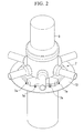
Fig. 2 is a perspective view for describing a nuclear reactor vessel and an annular plate. -
Fig. 3 is a partially enlarged view ofFig. 1 . -
Fig. 4 is a view illustrating an example of a nuclear reactor vessel support structure according to a second embodiment of the present invention. -
Fig. 5 is a view illustrating an example of a nuclear reactor vessel support structure according to a third embodiment of the present invention. -
Fig. 6 is a view illustrating an example of a nuclear reactor vessel support structure according to a fourth embodiment of the present invention. -
Fig. 7 is a view illustrating an example of a nuclear reactor vessel support structure according to a fifth embodiment of the present invention. -
Fig. 8 is a view illustrating an example of a nuclear reactor vessel support structure according to a sixth embodiment of the present invention. - Hereinafter, a nuclear reactor vessel support structure according to an embodiment of the present invention will be described with reference to
Figs. 1 to 3 .
As shown inFig. 1 , a nuclear reactorvessel support structure 1 according to the present embodiment is configured to support anuclear reactor vessel 3 at an inner peripheral side of a tube-shapedstructure 2 which is a structure of a nuclear reactor building.
The tube-shapedstructure 2 includes an inner peripheral tube-shapedsteel plate 4 of a cylindrical shape extending in a vertical direction, an outer peripheral tube-shapedsteel plate 6, and an intermediate tube-shapedsteel plate 5 disposed between the inner and outer peripheral tube-shaped steel plates. Further, an inner peripheral side concrete C1 is placed between the inner peripheral tube-shapedsteel plate 4 and the intermediate tube-shapedsteel plate 5 and an outer peripheral side concrete C2 is placed between the intermediate tube-shapedsteel plate 5 and the outer peripheral tube-shapedsteel plate 6.
The inner peripheral tube-shapedsteel plate 4 is formed to have a height lower than those of the intermediate tube-shapedsteel plate 5 and the outer peripheral tube-shapedsteel plate 6. - The nuclear reactor
vessel support structure 1 includes asupport 14 having a cylindrical tube-shapedplate 12 which is disposed on the inner peripheral side of the intermediate tube-shapedsteel plate 5, and a cylindricalannular plate 13 to which a radial support (a connection part) 7 is affixed, which protrudes to the inner peripheral side of the cylindrical tube-shapedplate 12 and is connected to thenuclear reactor vessel 3.
As shown inFig. 2 , theradial support 7 includes a plurality ofradial support keys 7a which are disposed around thenuclear reactor vessel 3 in a circumferential direction. Further, the plurality ofradial support keys 7a are connected with each other and alternately affixed to thenuclear reactor vessel 3 and theannular plate 13. - Further, as shown in
Fig. 3 , theannular plate 13 of thesupport 14 is affixed to the inner peripheral side concrete C1 by foundation bolts (first bar members) 15 extending in a vertical direction. The tube-shapedplate 12 of thesupport 14 is affixed to the intermediate tube-shapedsteel plate 5 by anchor bolts (second bar members) 16 extending in a radial direction of the tube-shapedstructure 2. - The
annular plate 13 is disposed above the inner peripheral tube-shapedsteel plate 4 and alower surface 13a thereof abuts a surface of the inner peripheral side concrete C1.
Further, theannular plate 13 is provided with a plurality of throughholes 13c that have thefoundation bolts 15 penetrating therethrough in a vertical direction so as to be inserted thereinto and are disposed at a predetermined interval in a circumferential direction.
A plurality ofribs 17 protruding downward are formed on alower surface 13a of theannular plate 13. The plurality ofribs 17 are steel plates having a substantially triangular shape and are disposed at a predetermined interval in a circumferential direction of theannular plate 13.
Thefoundation bolt 15 is installed to have alower end 15a side buried in the inner peripheral side concrete C1 and anupper end 15b side protruding upward from the inner peripheral side concrete C1. Further, the plurality offoundation bolts 15 is disposed at a predetermined interval in the circumferential direction of the tube-shapedstructure 2.
In addition, theupper end 15b sides of thefoundation bolts 15 are inserted into the throughholes 13c of theannular plate 13 and thefoundation bolts 15 are screwed with nuts 15c such that theannular plate 13 is affixed to the inner peripheral side concrete. - The tube-shaped
plate 12 is provided with a plurality of throughholes 12c that have theanchor bolts 16 penetrating therethrough in a radial direction so as to be inserted thereinto and are disposed at a predetermined interval in a circumferential direction.
Theanchor bolt 16 is installed to have a radialouter end 16a side buried in the outer peripheral side concrete C2 and a radialinner end 16b side protruding to the inner side of the intermediate tube-shapedsteel plate 5. Meanwhile, throughholes 5c into which theanchor bolts 16 are inserted are formed in the intermediate tube-shapedsteel plate 5.
Further, the plurality ofanchor bolts 16 is disposed at a predetermined interval in a circumferential direction and a vertical direction.
In addition, theanchor bolts 16 are mounted to have the radialinner end 16b sides inserted into the throughholes 12c of the tube-shapedplate 12 and are screwed with the nuts 16c such that the tube-shapedplate 12 is affixed to the outer peripheral side concrete.
Further, afiller 18, such as a grout, a shim, and the like, is filled between the tube-shapedplate 12 and the intermediate tube-shapedsteel plate 5. Thefiller 18 is disposed to adjust the radial position of thesupport 14 by adjusting the interval between the tube-shapedplate 12 and the intermediate tube-shapedsteel plate 5. - Next, a construction method of the foregoing nuclear reactor
vessel support structure 1 will be described with reference to the drawings. - First, the inner peripheral tube-shaped
steel plate 4, the intermediate tube-shapedsteel plate 5, and the outer peripheral tube-shapedsteel plate 6 are installed at a predetermined interval from one another in a radial direction. - Next, the concrete is poured between the inner peripheral tube-shaped
steel plate 4 and the intermediate tube-shapedsteel plate 5 and between the intermediate tube-shapedsteel plate 5 and the outer peripheral tube-shapedsteel plate 6 to a lower height than a position at which thesupport 14, thefoundation bolts 15, and theanchor bolts 16 are installed. - Next, the
support 14 is installed at a predetermined position along with thefoundation bolts 15 and theanchor bolt 16 to adjust the position. In this case, thesupport 14 is temporarily fastened if necessary. - Next, the concrete is poured between the inner peripheral tube-shaped
steel plate 4 and the intermediate tube-shapedsteel plate 5 and between the intermediate tube-shapedsteel plate 5 and the outer peripheral tube-shapedsteel plate 6, and thefoundation bolts 15 and theanchor bolts 16 are buried in the concrete.
After the concrete is cured, thefiller 18 is filled between the tube-shapedplate 12 and the intermediate tube-shapedsteel plate 5 to adjust the radial position of thesupport 14.
Thesupport 14 is affixed to the tube-shapedstructure 2 by the foregoing method. - Next, an effect of the foregoing nuclear reactor
vessel support structure 1 will be described with reference to the drawings.
In accordance with the nuclear reactorvessel support structure 1 according to the first embodiment, thesupport 14 is affixed to the inner peripheral side concrete C1 by thefoundation bolts 15 and is affixed to the inner peripheral side tube-shapedsteel plate 4 by theanchor bolts 16. Therefore, thesupport 14 can resist the out-of-plane bending load applied thereto with thefoundation bolts 15 and thesupport 14 can resist the shearing load applied thereto with theanchor bolts 16. Further, thesupport 14 and the tube-shapedstructure 2 can be integrated without welding. Therefore, it is possible to prevent thermal distortion (deformation) due to welding and to prevent thesupport 14 and the tube-shapedstructure 2 from being deformed at the bonded portion thereof. - In addition, the radial position of the
support 14 for the tube-shapedstructure 2 can be adjusted by thefiller 18 filled between the tube-shapedplate 12 and the intermediate tube-shapedsteel plate 5.
Further, thesupport 14 can resist the shearing load applied thereto with therib 17 formed on thelower surface 13a of theannular plate 13. - Next, other embodiments will be described with reference to the accompanying drawings, but the same or similar members and portions from the foregoing first embodiment will be denoted by the same reference signs, the description thereof will be omitted, and only components different from the first embodiment will be described.
- As shown in
Fig. 4 , a nuclear reactorvessel support structure 21 according to a second embodiment includes a plurality of studs (first studs, first bar members) 22 which are installed on thelower surface 13a of theannular plate 13, instead of the foundation bolt 15 (seeFig. 3 ) in the first embodiment.
Thestuds 22 are installed on the whole lower surface of theannular plate 13. Thestuds 22 may be attached when thesupport 14 is manufactured in advance. Therefore, a work load on site may be reduced. - In accordance with the nuclear reactor
vessel support structure 21 according to the second embodiment, thesupport 14 can resist the out-of-plane bending load applied thereto with thestuds 22. Therefore, the same effect as the first embodiment can be obtained. Further, thestuds 22 are evenly installed on the wholelower surface 13a of theannular plate 13. Therefore, the load applied to theannular plate 13 can be dispersed throughout the inner peripheral side concrete C1. - As shown in
Fig. 5 , a nuclear reactorvessel support structure 31 according to a third embodiment includes high strength bolts (second bar members) 33 that bond the tube-shapedplate 12 to the intermediate tube-shapedsteel plate 5 through asplice plate 32, instead of the anchor bolts 16 (seeFig. 3 ) according to the first embodiment.
In the present embodiment, the intermediate tube-shapedsteel plate 5 is divided in a vertical direction and the tube-shapedplate 12 is disposed between the intermediate tube-shapedsteel plates 5 which are divided vertically. - Further, in the upper and lower sides of the tube-shaped
plate 12, thesplice plate 32 is disposed over both the tube-shapedplate 12 and the intermediate tube-shapedsteel plate 5. The tube-shapedplate 12 and thesplice plate 32 are affixed to each other by thehigh strength bolts 33, and the intermediate tube-shapedsteel plate 5 and thesplice plate 32 are affixed to each other by thehigh strength bolts 33.
In the present embodiment, the tube-shapedplate 12 is formed of a thicker steel plate than the intermediate tube-shapedsteel plate 5. Therefore, ashim 34 for adjusting the thickness is installed between the intermediate tube-shapedsteel plate 5 and thesplice plate 32. Additionally, when the tube-shapedplate 12 is a thinner steel plate than the intermediate tube-shapedsteel plate 5, theshim 34 may be installed between the tube-shapedplate 12 and thesplice plate 32. - Further, a stud (second stud) 35 has one end bonded to the outer peripheral side of the tube-shaped
plate 12 and the other end buried in the outer peripheral side concrete C2. - In accordance with the nuclear reactor
vessel support structure 31 according to the third embodiment, the tube-shapedplate 12 and the intermediate tube-shapedsteel plate 5 can be integrated through thesplice plate 32 by thehigh strength bolts 33. Therefore, the same effect as the first embodiment is obtained.
Further, thestud 35 has one end bonded to the outer peripheral side of the tube-shapedplate 12 and the other end buried in the outer peripheral side concrete C2. Therefore, thesupport 14 can resist the shearing load applied thereto with the stud.
Further, the position of thesupport 14 for the tube-shapedstructure 2 can be adjusted by adjusting the thickness of theshim 34. - As shown in
Fig. 6 , a nuclear reactorvessel support structure 41 according to a fourth embodiment includes the studs (first studs, first bar members) 22 which are installed on thelower surface 13a of theannular plate 13 as in the second embodiment, instead of the foundation bolt 15 (seeFig. 4 ) according to the third embodiment.
In accordance with the nuclear reactorvessel support structure 41 according to the fourth embodiment, the same effect as the third embodiment is obtained. - As shown in
Fig. 7 , a nuclear reactorvessel support structure 51 according to a fifth embodiment includes a tube-shapedbody 52 which is bonded to the inner peripheral side of theannular plate 13 so as to protrude downward therefrom. Further, the tube-shapedbody 52 is disposed on the upper portion of the inner peripheral tube-shapedsteel plate 4 and is bonded to the inner peripheral tube-shapedsteel plate 4 through asplice plate 53 disposed over the second tube-shapedplate 52 and the inner peripheral side tube-shapedsteel 4 by high strength bolts (second bar members) 54.
Additionally, inFig. 7 , thesplice plate 53 is disposed at both the second tube-shapedplate 52 and the inner peripheral tube-shapedsteel plate 4, but may be disposed at one side thereof (the side on which nuts are fastened).
The second tube-shapedplate 52 is welded to theannular plate 13 in advance by, for example, welding, and the like.
Further, the tube-shapedplate 12 is disposed on the inner peripheral side of the intermediate tube-shapedsteel plate 5 and thefiller 18 is filled between the tube-shapedplate 12 and the intermediate tube-shapedsteel plate 5. The radial position of thesupport 14 is adjusted by thefiller 18. - In accordance with the nuclear reactor
vessel support structure 51 according to the fifth embodiment, the second tube-shapedplate 52 is affixed to the inner peripheral tube-shapedsteel plate 4 by thehigh strength bolts 54 and thesupport 14 can resist the shearing load applied thereto with thehigh strength bolts 54. Therefore, the same effect as the first embodiment is obtained. - As shown in
Fig. 8 , a nuclear reactorvessel support structure 61 according to the sixth embodiment includes the studs (first studs, first bar members) 22 which are installed on thelower surface 13a of theannular plate 13 as in the second embodiment, instead of the foundation bolt 15 (seeFig. 7 ) according to the fifth embodiment.
According to a nuclear reactorvessel support structure 61 according to the sixth embodiment, the same effect as the fifth embodiment is obtained. - The support structure of the nuclear reactor vessel support structure according to the present invention has been described above, but the present invention is not limited to the foregoing embodiments and may be changed without departing from the scope of the present invention.
For example, in the foregoing embodiments, therib 17 is formed on thelower surface 13a of theannular plate 13. However, a configuration that does not include therib 17 may be allowed.
Further, in the foregoing fifth and sixth embodiments, the tube-shapedplate 12 is not affixed to the intermediate tube-shapedsteel plate 5. However, as in the first embodiment, the tube-shapedplate 12 may be affixed to the intermediate tube-shapedsteel plate 5 by theanchor bolts 16.
Further, in the foregoing embodiments, thehigh strength bolts high strength bolts
Further, in the foregoing embodiments, therib 17 is configured of the steel plate having a substantially triangular shape. However, the rib may be formed in other shapes. - According to the present invention, the support is affixed to the concrete placed between the inner peripheral tube-shaped steel plate and the intermediate tube-shaped steel plate by the first bar member extending in a vertical direction. In addition, the support is affixed to the inner peripheral tube-shaped steel plate or the intermediate tube-shaped steel plate by the second bar member extending in a radial direction of the tube-shaped structure. Therefore, the support can resist the out-of-plane bending load applied thereto with the first bar member. Further, the support can resist the shearing load applied thereto with the second bar member. The support can be bonded to the tube-shaped structure without the welding. Thermal distortion (deformation) due to welding does not occur. Therefore, it is possible to prevent the support and the tube-shaped structure from being deformed at the bonded portion thereof.
-
- 1, 21, 31, 41, 51, 61:
- nuclear reactor vessel support structure
- 2:
- tube-shaped structure
- 3:
- nuclear reactor vessel
- 4:
- inner peripheral tube-shaped steel plate
- 5:
- intermediate tube-shaped steel plate
- 6:
- outer peripheral tube-shaped steel plate
- 7:
- radial support (connection part)
- 12:
- tube-shaped plate
- 13:
- annular plate
- 13a:
- lower surface
- 14:
- support
- 15:
- foundation bolt (first bar member)
- 16:
- anchor bolt (second bar member)
- 17:
- rib
- 18:
- filler
- 22:
- stud (first stud, first bar member)
- 32, 53:
- splice plate
- 33, 54:
- high strength bolt (second bar member)
- 34:
- shim
- 35:
- stud (second stud)
- 52:
- tube-shaped plate
Claims (11)
- A nuclear reactor vessel support structure which comprises an inner peripheral tube-shaped steel plate, an outer peripheral tube-shaped steel plate, and an intermediate tube-shaped steel plate disposed between the inner and outer peripheral tube-shaped steel plates and is configured to support a nuclear reactor vessel on the inner peripheral side of a tube-shaped structure formed by pouring concrete between the inner peripheral tube-shaped steel plate and the intermediate tube-shaped steel plate and between the intermediate tube-shaped steel plate and the outer peripheral tube-shaped steel plate, the nuclear reactor vessel support structure comprising:a support which has a tube-shaped plate disposed on the inner peripheral side of the intermediate tube-shaped steel plate, and an annular plate which protrudes to the inner peripheral side of the tube-shaped plate and to which a connection part connected to the nuclear reactor vessel is affixed,wherein the support is affixed to the concrete placed between the inner peripheral tube-shaped steel plate and the intermediate tube-shaped steel plate by a first bar member extending in a vertical direction and affixed to the inner peripheral tube-shaped steel plate or the intermediate tube-shaped steel plate by a second bar member extending in a radial direction of the tube-shaped structure.
- The nuclear reactor vessel support structure according to Claim 1, wherein the first bar member is a foundation bolt of which a lower end side is buried in the concrete placed between the inner peripheral tube-shaped steel plate and the intermediate tube-shaped steel plate and an upper end side is inserted into a through hole formed in the annular plate to affix the annular plate.
- The nuclear reactor vessel support structure according to Claim 1, wherein the first bar member is a first stud which is bonded to a lower surface of the annular plate and buried in the concrete placed between the inner peripheral tube-shaped steel plate and the intermediate tube-shaped steel plate.
- The nuclear reactor vessel support structure according to any one of Claims 1 to 3, wherein the second bar member is an anchor bolt which has a radial outer end side inserted into the through hole formed in the intermediate tube-shaped steel plate and buried in the concrete placed between the intermediate tube-shaped steel plate and the outer peripheral tube-shaped steel plate, and a radial inner end side inserted into the through hole formed in the tube-shaped plate and affixes the tube-shaped plate, and
a filler is filled between the intermediate tube-shaped steel plate and the tube-shaped plate. - The nuclear reactor vessel support structure according to any one of Claims 1 to 3, wherein the intermediate tube-shaped steel plate is divided vertically into two portions disposed above and below the tube-shaped plate, and a splice plate is disposed over the tube-shaped plate and the intermediate tube-shaped steel plate, and
the second bar member is a bolt which connects the tube-shaped plate with the splice plate and a bolt which joins the divided body to the splice plate. - The nuclear reactor vessel support structure according to Claim 5, further comprising:a shim being disposed between the splice plate and the tube-shaped plate or the intermediate tube-shaped steel plate to adjust an interval between the splice plate and the tube-shaped plate or the intermediate tube-shaped steel plate.
- The nuclear reactor vessel support structure according to Claim 5 or 6, wherein a second stud buried in the concrete placed between the inner tube-shaped steel plate and the intermediate tube-shaped steel plate is bonded to the outer peripheral surface of the tube-shaped plate.
- The nuclear reactor vessel support structure according to any one of Claims 1 to 3, wherein the support includes a tube-shaped body that protrudes downward from the inner peripheral side of the annular plate and is disposed on the upper portion of the inner peripheral tube-shaped steel plate, and a splice plate is disposed over the tube-shaped body and the inner peripheral tube-shaped steel plate,
the second bar member is a bolt which connects the second tube-shaped plate with the splice plate and a bolt which joins the inner peripheral tube-shaped steel plate and the splice plate, and
a filler is filled between the tube-shaped plate and the intermediate tube-shaped steel plate. - The nuclear reactor vessel support structure of Claim 8, wherein the second bar member is the bolt, and an anchor bolt which has the radial outer end side inserted into the through hole formed in the intermediate tube-shaped steel plate and buried in the concrete placed between the intermediate tube-shaped steel plate and the outer peripheral tube-shaped steel plate and the radial inner end side inserted into the through hole formed in the tube-shaped plate to affix the tube-shaped plate.
- The nuclear reactor vessel support structure according to any one of Claims 1 to 9, wherein a rib protruding downward is formed on the lower surface of the annular plate.
- A construction method of the nuclear reactor vessel support structure according to any one of Claims 1 to 9, comprising:a tube-shaped steel plate installing process of installing an inner peripheral tube-shaped steel plate, an outer peripheral tube-shaped steel plate, and an intermediate tube-shaped steel plate;a first concrete pouring process of pouring a concrete in a position between the inner peripheral tube-shaped steel plate and the intermediate tube-shaped steel plate and between the outer peripheral tube-shaped steel plate and the intermediate tube-shape steel plate, to a lower height than a position at which a first bar member and a second bar member are installed;a support installing process of installing the support along with the first bar member and affixing the support to the inner peripheral tube-shaped steel or the intermediate tube-shaped steel plate by the second bar member; anda second concrete pouring process of pouring a concrete in a position at which the support, the first bar member, and the second bar member are installed.
Applications Claiming Priority (2)
| Application Number | Priority Date | Filing Date | Title |
|---|---|---|---|
| JP2010277203A JP5660876B2 (en) | 2010-12-13 | 2010-12-13 | Reactor vessel support structure and construction method of reactor vessel support structure |
| PCT/JP2011/078176 WO2012081449A1 (en) | 2010-12-13 | 2011-12-06 | Structure for supporting nuclear reactor vessel and method for building structure for supporting nuclear reactor vessel |
Publications (2)
| Publication Number | Publication Date |
|---|---|
| EP2654042A1 true EP2654042A1 (en) | 2013-10-23 |
| EP2654042A4 EP2654042A4 (en) | 2017-07-19 |
Family
ID=46244557
Family Applications (1)
| Application Number | Title | Priority Date | Filing Date |
|---|---|---|---|
| EP11849465.7A Withdrawn EP2654042A4 (en) | 2010-12-13 | 2011-12-06 | Structure for supporting nuclear reactor vessel and method for building structure for supporting nuclear reactor vessel |
Country Status (4)
| Country | Link |
|---|---|
| US (1) | US9548140B2 (en) |
| EP (1) | EP2654042A4 (en) |
| JP (1) | JP5660876B2 (en) |
| WO (1) | WO2012081449A1 (en) |
Families Citing this family (3)
| Publication number | Priority date | Publication date | Assignee | Title |
|---|---|---|---|---|
| JP7045864B2 (en) * | 2018-01-23 | 2022-04-01 | 三菱重工業株式会社 | Fixing part load distribution structure |
| CN115274147B (en) * | 2022-07-29 | 2025-10-03 | 华能核能技术研究院有限公司 | pressure vessels |
| CN117877772A (en) * | 2024-02-06 | 2024-04-12 | 上海核工程研究设计院股份有限公司 | Modular support device for pressure vessel |
Family Cites Families (23)
| Publication number | Priority date | Publication date | Assignee | Title |
|---|---|---|---|---|
| US2890009A (en) * | 1955-07-13 | 1959-06-09 | Combustion Eng | Vessel support |
| US3129836A (en) * | 1963-02-04 | 1964-04-21 | Dow Chemical Co | Supporting structure for reactor vessels |
| US3414472A (en) * | 1966-07-12 | 1968-12-03 | Stone & Webster Eng Corp | Nuclear reactor direct pressure suppression containment |
| JPS5412159Y2 (en) * | 1975-05-19 | 1979-05-29 | ||
| JPS5325916A (en) * | 1976-08-24 | 1978-03-10 | Toshiba Corp | Construction method of lining storage tank and accessory unit |
| US4209889A (en) * | 1978-02-27 | 1980-07-01 | Olin Corporation | Corrosion resistant fastening system and method |
| JPS588757B2 (en) * | 1979-10-17 | 1983-02-17 | 三菱原子力工業株式会社 | Reactor vessel support device |
| JPS5814088A (en) * | 1981-07-20 | 1983-01-26 | 石川島播磨重工業株式会社 | Reactor pressure vessel support structure |
| JPS58103694A (en) * | 1981-12-15 | 1983-06-20 | 株式会社日立製作所 | Basic structure of reactor pressure vessel and its construction method |
| JPS58196491A (en) * | 1982-05-12 | 1983-11-15 | 株式会社日立製作所 | Reactor main base structure |
| US4508677A (en) * | 1983-02-09 | 1985-04-02 | General Electric Company | Modular nuclear reactor for a land-based power plant and method for the fabrication, installation and operation thereof |
| JPS59187290A (en) * | 1983-04-06 | 1984-10-24 | 株式会社日立製作所 | Installation structure of reactor pressure vessel |
| JPS60219587A (en) | 1984-04-16 | 1985-11-02 | 株式会社日立製作所 | exhaust pipe support |
| JPS6126197U (en) * | 1984-07-23 | 1986-02-17 | バブコツク日立株式会社 | Pressure vessel support skirt cooling system |
| US5102612A (en) * | 1989-06-09 | 1992-04-07 | Combustion Engineering, Inc. | Permanent refueling pool seal |
| JPH041492U (en) * | 1990-04-18 | 1992-01-08 | ||
| TW299381B (en) * | 1991-08-13 | 1997-03-01 | Mitsubishi Heavy Ind Ltd | |
| CA2133423A1 (en) * | 1992-04-03 | 1993-10-04 | Gunter Liersch | Gastight wall |
| JP2000346973A (en) * | 1999-03-31 | 2000-12-15 | Toshiba Corp | Reactor containment vessel |
| US7497054B2 (en) * | 2001-06-06 | 2009-03-03 | Nippon Steel Corporation | Column-and-beam join structure |
| JP4875333B2 (en) | 2005-09-21 | 2012-02-15 | 三菱重工業株式会社 | Inspection device |
| US8401142B2 (en) * | 2007-02-20 | 2013-03-19 | Westinghouse Electric Company Llc | Nuclear reactor vessel fuel thermal insulating barrier |
| JP2008275368A (en) | 2007-04-26 | 2008-11-13 | Hitachi-Ge Nuclear Energy Ltd | Reactor containment equipment |
-
2010
- 2010-12-13 JP JP2010277203A patent/JP5660876B2/en active Active
-
2011
- 2011-12-06 WO PCT/JP2011/078176 patent/WO2012081449A1/en not_active Ceased
- 2011-12-06 EP EP11849465.7A patent/EP2654042A4/en not_active Withdrawn
- 2011-12-06 US US13/992,999 patent/US9548140B2/en active Active
Non-Patent Citations (1)
| Title |
|---|
| See references of WO2012081449A1 * |
Also Published As
| Publication number | Publication date |
|---|---|
| JP2012127690A (en) | 2012-07-05 |
| US9548140B2 (en) | 2017-01-17 |
| WO2012081449A1 (en) | 2012-06-21 |
| US20130272485A1 (en) | 2013-10-17 |
| EP2654042A4 (en) | 2017-07-19 |
| JP5660876B2 (en) | 2015-01-28 |
Similar Documents
| Publication | Publication Date | Title |
|---|---|---|
| JP6140209B2 (en) | Exposed column base joint structure | |
| KR102268071B1 (en) | Apparatus for reinforcing the pile head | |
| JP4499006B2 (en) | Seismic isolation device mounting structure, construction method thereof, and base plate for seismic isolation device mounting | |
| US9548140B2 (en) | Nuclear reactor vessel support structure and construction method of nuclear reactor vessel support structure | |
| JP6829631B2 (en) | Construction method of column base, reinforcement method of existing column base | |
| KR20170139186A (en) | Connecting structure between column and footing structure | |
| JP6842296B2 (en) | Foundation structure | |
| JP2018053563A (en) | Column base anchor structure of a column having a steel frame and its construction method | |
| JP2018104946A (en) | Column base structure, and method to reinforce column base | |
| JP5785647B2 (en) | Installation structure of base plate assembly for seismic isolation device | |
| JP6964407B2 (en) | Column base structure and its construction method | |
| JP5619459B2 (en) | Installation structure of base plate assembly for seismic isolation device | |
| JP4124031B2 (en) | How to install seismic isolation devices on existing pillars | |
| JP7340416B2 (en) | Steel column base structure | |
| JP5344702B2 (en) | Column and slab joint structure | |
| JP2019090195A (en) | Support structure of columnar structure | |
| JP5353130B2 (en) | Finishing method for reinforced columns, mounting structure for reinforced column finishing materials | |
| JP6364210B2 (en) | Bridge pier reinforcement structure | |
| JP2017082548A (en) | Concrete foundation joint member and pile structure | |
| JP2021195834A (en) | Column base anchor structure, trestle, and design method for column base anchor structure | |
| JP5522775B2 (en) | Column base structure | |
| JP7720237B2 (en) | Seismic isolation structure and construction method thereof | |
| JP5436316B2 (en) | Foundation structure of steel column base | |
| JP2017048593A (en) | Reinforcement structure and reinforcement method for existing columns | |
| JP4350758B2 (en) | Column base anchor device |
Legal Events
| Date | Code | Title | Description |
|---|---|---|---|
| PUAI | Public reference made under article 153(3) epc to a published international application that has entered the european phase |
Free format text: ORIGINAL CODE: 0009012 |
|
| 17P | Request for examination filed |
Effective date: 20130610 |
|
| AK | Designated contracting states |
Kind code of ref document: A1 Designated state(s): AL AT BE BG CH CY CZ DE DK EE ES FI FR GB GR HR HU IE IS IT LI LT LU LV MC MK MT NL NO PL PT RO RS SE SI SK SM TR |
|
| DAX | Request for extension of the european patent (deleted) | ||
| RA4 | Supplementary search report drawn up and despatched (corrected) |
Effective date: 20170621 |
|
| RIC1 | Information provided on ipc code assigned before grant |
Ipc: G21C 13/024 20060101AFI20170614BHEP Ipc: F22B 37/24 20060101ALI20170614BHEP |
|
| GRAP | Despatch of communication of intention to grant a patent |
Free format text: ORIGINAL CODE: EPIDOSNIGR1 |
|
| RIC1 | Information provided on ipc code assigned before grant |
Ipc: F22B 37/24 20060101ALI20180320BHEP Ipc: G21C 13/024 20060101AFI20180320BHEP |
|
| INTG | Intention to grant announced |
Effective date: 20180423 |
|
| STAA | Information on the status of an ep patent application or granted ep patent |
Free format text: STATUS: THE APPLICATION IS DEEMED TO BE WITHDRAWN |
|
| 18D | Application deemed to be withdrawn |
Effective date: 20180904 |