EP2653783A2 - Turbine combustor system having aerodynamic feed cap - Google Patents
Turbine combustor system having aerodynamic feed cap Download PDFInfo
- Publication number
- EP2653783A2 EP2653783A2 EP13163005.5A EP13163005A EP2653783A2 EP 2653783 A2 EP2653783 A2 EP 2653783A2 EP 13163005 A EP13163005 A EP 13163005A EP 2653783 A2 EP2653783 A2 EP 2653783A2
- Authority
- EP
- European Patent Office
- Prior art keywords
- back plate
- fuel nozzle
- chamber
- feed cap
- fuel
- Prior art date
- Legal status (The legal status is an assumption and is not a legal conclusion. Google has not performed a legal analysis and makes no representation as to the accuracy of the status listed.)
- Granted
Links
Images

Classifications
-
- F—MECHANICAL ENGINEERING; LIGHTING; HEATING; WEAPONS; BLASTING
- F23—COMBUSTION APPARATUS; COMBUSTION PROCESSES
- F23R—GENERATING COMBUSTION PRODUCTS OF HIGH PRESSURE OR HIGH VELOCITY, e.g. GAS-TURBINE COMBUSTION CHAMBERS
- F23R3/00—Continuous combustion chambers using liquid or gaseous fuel
- F23R3/28—Continuous combustion chambers using liquid or gaseous fuel characterised by the fuel supply
- F23R3/286—Continuous combustion chambers using liquid or gaseous fuel characterised by the fuel supply having fuel-air premixing devices
-
- F—MECHANICAL ENGINEERING; LIGHTING; HEATING; WEAPONS; BLASTING
- F23—COMBUSTION APPARATUS; COMBUSTION PROCESSES
- F23D—BURNERS
- F23D14/00—Burners for combustion of a gas, e.g. of a gas stored under pressure as a liquid
- F23D14/46—Details
- F23D14/62—Mixing devices; Mixing tubes
- F23D14/64—Mixing devices; Mixing tubes with injectors
-
- F—MECHANICAL ENGINEERING; LIGHTING; HEATING; WEAPONS; BLASTING
- F23—COMBUSTION APPARATUS; COMBUSTION PROCESSES
- F23D—BURNERS
- F23D2209/00—Safety arrangements
- F23D2209/10—Flame flashback
-
- F—MECHANICAL ENGINEERING; LIGHTING; HEATING; WEAPONS; BLASTING
- F23—COMBUSTION APPARATUS; COMBUSTION PROCESSES
- F23D—BURNERS
- F23D2900/00—Special features of, or arrangements for burners using fluid fuels or solid fuels suspended in a carrier gas
- F23D2900/14—Special features of gas burners
- F23D2900/14021—Premixing burners with swirling or vortices creating means for fuel or air
-
- F—MECHANICAL ENGINEERING; LIGHTING; HEATING; WEAPONS; BLASTING
- F23—COMBUSTION APPARATUS; COMBUSTION PROCESSES
- F23D—BURNERS
- F23D2900/00—Special features of, or arrangements for burners using fluid fuels or solid fuels suspended in a carrier gas
- F23D2900/14—Special features of gas burners
- F23D2900/14701—Swirling means inside the mixing tube or chamber to improve premixing
Definitions
- the subject matter disclosed herein relates to turbine combustors, and, more particularly, to a system for creating aerodynamic flow within a turbine combustor head end chamber.
- a gas turbine engine combusts a fuel-air mixture in a combustion chamber of a turbine combustor, and then drives one or more turbines with the resulting hot combustion gases.
- fuel and air are pre-mixed prior to ignition to reduce emissions and improve combustion.
- the gas turbine engine mixes the fuel and the air within one or more chambers, such as fuel nozzles.
- the fuel and air may travel together and/or separately through one or more paths through the turbine combustor.
- the one or more paths may include sharp turns, recesses, and other obstructions that create recirculation zones, which may allow the flame holding and/or flashback.
- the invention resides in a system including a turbine combustor having a fuel nozzle with an inner shell and an outer shell and an feed cap disposed about the fuel nozzle having an outer wall and a back plate.
- the back plate joins respective upstream ends of the outer shell of the fuel nozzle and the outer wall of the feed cap.
- the turbine combustor is configured to flow a first pressurized air via a first air path extending along the outer wall of the feed cap, the back plate of the feed cap, and into the fuel nozzle.
- the invention resides in a system including a turbine combustor having:a combustion chamber, a head end chamber separated from the combustion chamber by a divider plate, and a pressurized chamber disposed in the head end chamber and about a fuel nozzle.
- the pressurized chamber includes a back plate that is joined to an upstream end of an outer shell of the fuel nozzle.
- the invention resides in a system including a turbine combustor having a combustion chamber, a head end chamber separated from the combustion chamber by a divider plate, and an air path disposed in the head end chamber and configured to flow a first pressurized air into a fuel nozzle.
- the air path includes a first segment disposed between a flow sleeve of the turbine combustor and an outer wall of an feed cap, and a second segment disposed downstream of the first segment and between a back plate of the feed cap and an end plate of the head end chamber.
- the second segment is substantially free of any flow-impeding surfaces between the back plate and the end plate.
- the air path also includes a third segment disposed downstream of the second segment and between inner and outer shells of the fuel nozzle.
- a head end of a gas turbine combustor which is upstream from a combustion chamber, include areas that are generally not aerodynamic, such as areas that create turbulent flow via one or more sharp turns or edges, areas having low flow conditions where pockets of compressed air and fuel can accumulate, and areas where mixing of fuel and air is undesirable.
- the head end of the gas turbine combustor may include recirculation zones, which may include zones in which a mixture of fuel and air has low flow or research relates such that a flame can hold or flash back.
- any one or a combination of these conditions can lead to undesirable combustion (e.g., flame holding or flashback) upstream from the combustion chamber of the gas turbine combustor, such as within a head end region or a feed cap region of the gas turbine combustor.
- the present embodiments include an aerodynamic feed cap design and the head end of the gas turbine combustor to reduce or eliminate recirculation zones.
- the feed cap may be a one-piece design configured to reduce the possibility forming low-flow regions, no-flow regions, areas of undesired turbulence, recirculation, mixing of fuel and air, and the like.
- the present embodiments may provide enhanced reliability of gas turbine engines, which in turn may result in more reliable energy production and increased throughput in integrated gasification systems, such as integrated gasification combined cycle (IGCC) systems.
- IGCC integrated gasification combined cycle
- the present embodiments may be used in any context employing a turbine combustor having areas where low-flow, no-flow, turbulence, and/or recirculation may create undesirable situations (e.g., flashback or flame holding).
- FIG. 1 illustrates a block diagram of an embodiment of a gas turbine system 10, which may utilize an aerodynamic feed cap in accordance with present embodiments.
- the system 10 includes a compressor 12, turbine combustors 14, and a turbine 16.
- the turbine combustors 14 include fuel nozzles 18 which route a liquid fuel and/or gas fuel, such as natural gas or syngas, into the turbine combustors 14.
- each turbine combustor 14 may have multiple fuel nozzles 18. More specifically, the turbine combustors 14 may each include a primary fuel injection system having primary fuel nozzles 20 and a secondary fuel injection system having secondary fuel nozzles 22.
- each turbine combustor 14 may also include a feed cap configured to reduce undesirable no-flow, low-flow, recirculation, or other undesirable air flow situations.
- the aerodynamic feed cap of each turbine combustor 14 may mitigate acoustic waves and suppress pressure fluctuations (i.e., reduce the occurrence of dynamics) in the turbine combustor 14.
- a feed cap design may be desirable to mitigate the possibility of retaining a combustible mixture of fuel and air in a recirculation zone, such as a low velocity region. For example, in a recirculation zone, a flame can hold in this region and/or travel upstream to this region, which may be undesirable.
- the turbine combustors 14 ignite and combust an air-fuel mixture, and then pass hot pressurized combustion gasses 24 (e.g., exhaust) into the turbine 16.
- Turbine blades are coupled to a shaft 26, which is also coupled to several other components throughout the turbine system 10.
- the shaft 26 may be coupled to a load 30, which is powered via rotation of the shaft 26.
- the load 30 may be any suitable device that may generate power via the rotational output of the turbine system 10, such as an electrical generator, a propeller of an airplane, and so forth.
- Compressor blades are included as components of the compressor 12.
- the blades within the compressor 12 are coupled to the shaft 26, and will rotate as the shaft 26 is driven to rotate by the turbine 16, as described above.
- the rotation of the blades within the compressor 12 compress air from an air intake 32 into pressurized air 34.
- the pressurized air 34 is then fed into the fuel nozzles 18 of the turbine combustors 14.
- the fuel nozzles 18 mix the pressurized air 34 and fuel to produce a suitable mixture ratio for combustion (e.g., a combustion that causes the fuel to more completely burn) so as not to waste fuel or cause excess emissions.
- the compressed air may pass through and/or around the feed cap in each combustor 14 upstream from fuel injection.
- FIG. 2 is a schematic of an embodiment of one of the turbine combustors 14 of FIG. 1 , illustrating a feed cap 50 disposed within a head end 52 of the turbine combustor 14 and about a single fuel nozzle 20.
- the compressor 12 receives air from the air intake 32, compresses the air, and produces the flow of pressurized air 34 for use in the combustion process within the turbine combustor 14.
- the pressurized air 34 is received by a compressor discharge 54 that is operatively coupled to the turbine combustor 14.
- the pressurized air 34 flows from the compressor discharge 54 toward the head end 52 of the turbine combustor 14. More specifically, the pressurized air 34 flows through an annulus 60 between a liner 62 and a flow sleeve 64 of the turbine combustor 14 to reach the head end 52.
- the head end 52 includes an end plate 66 that may support the primary fuel nozzles 20 depicted in FIG. 1 .
- the head end 52 has the single primary fuel nozzle 20 and associated feed cap 50.
- the head end 52 may include a plurality of fuel nozzles 20, with one or more feed caps 50 surrounding the fuel nozzles 20.
- a single feed cap 50 may surround a plurality of the fuel nozzles 20, such as between 2 and 10 fuel nozzles (e.g., between 2 and 8 or 4 and 6 fuel nozzles).
- a fuel supply provides fuel 68 to the primary fuel nozzle 20.
- an air flow path 72 delivers the pressurized air 34 from the annulus 60 of the turbine combustor 14 through the primary fuel nozzle 20.
- the primary fuel nozzle 20 combines the pressurized air 34 with the fuel 68 provided by the primary fuel supply 68 to form an fuel-air mixture.
- the fuel 68 may be injected into the air flow path 72 by a plurality of swirl vanes 74 and, in some embodiments, additionally by one or more quaternary fuel injectors 97.
- the fuel-air mixture flows from the air flow path 72 into a combustion chamber 76 where the fuel-air mixture is ignited and combusted to form combustion gases (e.g., exhaust).
- the combustion gases flow in a direction 78 toward a transition piece 80 of the turbine combustor 14.
- the combustion gases pass through the transition piece 80, as indicated by arrow 82, toward the turbine 16, where the combustion gases drive the rotation of the blades within the turbine 16.
- the turbine combustor 14 includes regions where combustion is desired, such as the combustion chamber 76, and regions where combustion is undesirable, such as a head end chamber 84 disposed between the end plate 66 and a divider plate 86 separating the head end 52 from the combustion chamber 76.
- Combustion e.g., flashback and/or flame holding
- within the head end chamber 84 may be a result of turbulent air flow and fuel-air pockets along the air flow path 72, where the flow recirculates and/or has a low or no velocity in an upstream region, such as upstream of a combustion chamber and/or upstream of a fuel injector (e.g., fuel injector 20), and downstream of quaternary fuel injectors 97.
- a fuel injector e.g., fuel injector 20
- an aerodynamic back plate 88 connecting an outer wall 90 of the feed cap 50 with an outer shell 92 of the fuel nozzle 20.
- the back plate 88 connects the outer shell 92 of the fuel nozzle 20 with the outer wall 90 of the feed cap 50 in such a way that the pressurized air 34 is able to flow along the air flow path 72 without encountering substantial turbulence or pockets of low flow or no flow.
- the configuration of the back plate 88 may also help reduce the occurrence of pressure waves, acoustic waves, and other oscillations referred to as combustion dynamics, produced by the combustion process. Combustion dynamics may cause performance degradation, structural stresses, and mechanical or thermal fatigue in the turbine combustor 14 (e.g., within the head end chamber 84).
- the back plate 88, the outer wall 90 of the feed cap 50, the outer shell 92 of the fuel nozzle 20, and the divider plate 86 together define a closed volume or chamber 94.
- the chamber 94 receives an influx of preconditioned air 96 from the set of quaternary fuel injectors 97 at a pressure that may be equal to or greater than a pressure of the pressurized air 34 flowing along the air path 72. Therefore, relative to the air path 72 and head end chamber 84, the chamber 94 may be considered to be a pressurized chamber.
- the chamber 94 receives the preconditioned air 96 at a pressure that is between approximately 1 and 20% higher than the pressure of the pressurized air 34 and/or the air/fuel mixture flowing along the air path 72, such as between approximately 1 and 15%, 1 and 10%, 2 and 8%, 2 and 6%, or 3 and 5% (e.g., approximately 3%, 4%, or 5%) higher. Therefore, the chamber 94 may be sealed to the head end chamber 84, which may prevent an influx of the fuel and/or the air/fuel mixture from entering the chamber 94. In preventing such an influx, the chamber 94 may reduce the likelihood of premature combustion of the air/fuel mixture within the head end chamber 84 as a result of no flow or low flow of the air/fuel mixture.
- the chamber 94 may also enable cooling of the divider plate 86 by passing preconditioned air 96 into the combustion chamber 76.
- the preconditioned air 96 may be the pressurized air 34, or may be from another air source.
- the quaternary fuel injectors 97 may also inject fuel 86 into the air path 72 to form a fuel-air mixture. Accordingly, the configuration of the back plate 88, and in particular its manner of connection with the outer wall 90 of the feed cap 50 and the outer shell 92 of the fuel nozzle 20, reduces the possibility of flame holding and recirculation of the fuel-air mixture.
- FIG. 3 is a schematic of an embodiment of the head end 52 of the turbine combustor 14, taken within line 3-3 of FIG. 2 , illustrating the chamber 94, the quaternary fuel injectors 97, and the primary fuel nozzle 20 disposed within the head end chamber 84.
- the back plate 88 joins the outer wall 90 of the feed cap 50 with the outer shell 92 of the fuel nozzle 20. Specifically, the back plate 88 directly connects a head end terminus 98 of the outer wall 90 with a head end terminus 100 of the outer shell 92.
- the back plate 88 may take on any aerodynamic form, wherein a main portion 102 of the back plate 88 may be curved (e.g., concave or convex), sinuous, angled, or substantially parallel with respect to the end plate 66 and/or the divider plate 86, as discussed below with respect to FIGS. 5-7 .
- the back plate 88 may extend in a substantially straight line from the head end terminus 98 to the head end terminus 100, and may be substantially free of flow-impeding surfaces such as recesses or concave shapes(e.g., with respect to the termini 98, 100).
- the back plate 88 is substantially parallel with respect to the end plate 66 and/or the divider plate 86.
- substantially parallel includes configurations where the entirety of the first portion 102 is oriented to within approximately 2° of parallel with respect to either or both of the end plate 66 and the divider plate 86, accounting for manufacturing tolerances.
- configurations where the main portion 102 is angled with respect to the end plate 66 and/or the divider plate 86 is also presently contemplated, such as angled to between approximately 2 and 30°, 2 and 20°, 2 and 15°, 3 and 10°, or 4 and 8°.
- the main portion 102 is substantially parallel with respect to both the end plate 66 and the divider plate 86, and is rounded at its first and second edges 104, 106 where it connects to the outer wall 90 and the outer shell 92, respectively.
- the first and second edges 104, 106 may assume any edge configuration, including rounded edges, straight edges, beveled edges, protruding edges, or any edge that does not create shear forces on the pressurized air 34.
- the configuration of the back plate 88 facilitates flow of the pressurized air 34 and the fuel-air mixture along the air flow path 72.
- the air flow path 72 receives the pressurized air 34 from the annulus 60 of the turbine combustor 14.
- the quaternary fuel injectors 97 inject fuel 68 into the flow path 72 to form the fuel-air mixture, which may also flow along the air flow path 72.
- the air flow path 72 includes a first portion 120, a second portion 122, and a third portion 123. The first portion 120, the second portion 122, and the third portion 123 are operatively coupled.
- the first portion 120 of the air flow path 72 is defined by an outer wall 124, which may be a head end casing or the flow sleeve 64, and the outer wall 90 of the feed cap 50.
- the second portion 122 of the air flow path 72 is defined by the end plate 66 of the head end chamber 84 and the back plate 88 of the feed cap 50.
- the outer shell 92 and an inner shell 130 of the fuel nozzle 20 define the third portion 123.
- the flow of the pressurized air 34 and/or the fuel-air mixture flows along an outer surface of the pressurized chamber 94 including a first outer surface of the feed cap 50 disposed around the fuel nozzle 20, an outer surface of the back plate 88, and an outer surface of the outer shell 92 of the fuel nozzle 20.
- the back plate 88 is disposed at the juncture of the first and second portions 120, 122 and the juncture of the second and third portions 122, 123.
- the shape and positioning of the back plate 88 may facilitate flow of the pressurized air 34 between each portion.
- the first edge 104 of the back plate 88 which couples the back plate 88 with the outer wall 90 of the feed cap 50, may be rounded so as to prevent turbulent, recirculating, and/or low-velocity flow as the pressurized air 34 and/or fuel-air mixture flows from the first portion 120 to the second portion 122.
- the second edge 106 of the back plate 88 which couples the back plate 88 with the outer shell 92 of the fuel nozzle 20, may be rounded so as to prevent turbulent, recirculating, and/or low-velocity flow as the pressurized air and/or fuel-air mixture flows from the second portion 122 to the third portion 123.
- the main portion 102 of the back plate 88 prevents the air and/or fuel-air flow from stalling.
- the main portion 102 prevents pockets of pressurized air 34 and/or the air/fuel mixture from becoming trapped in the second portion 122 by enabling continuous flow of the pressurized air 34 and/or the fuel-air mixture.
- the main portion 102 is shaped to prevent areas where a crosswise flow of air is formed in the second portion 122.
- the back plate 88 will not have any surfaces that create flow shearing, such as protrusions, obstructions, recesses, and so on.
- the outer wall 90, the back plate 88, and the outer shell 92 are configured such that the air path 72 is substantially free of no flow or low flow regions in which a flow of the pressurized air and/or fuel-air mixture is impeded, halted, or otherwise sheared. That is, the back plate 88 may be a substantially smooth, continuous surface.
- the pressurized air 34 flows from the annulus 60, first through the first portion 120 of the air flow path 72, through the second portion 122 of the air flow path 72, and then through the third portion 123.
- the pressurized air 34 may mix with the fuel 68, forming a fuel-air mixture. Therefore, in teh first, second, and third portions 120, 122, 123, the arrows 132 may also represent the fuel-air mixture.
- the pressurized air 34 and/or fuel-air mixture also flows around the swirl vanes 74. As discussed above, the fuel 68 is released into the pressurized air 34 through the swirl vanes 74.
- the fuel 68 flows down a fuel path 134 within the inner shell 130 of the fuel nozzle 20, as represented by arrows 136.
- the fuel 68 passes into the swirl vanes 74 from the fuel path 134, as represented by arrows 138, and exits the swirl vanes 74 through fuel ports 140 in the swirl vanes 74, as represented by arrows 142.
- the fuel 68 mixes with the pressurized air 34 to create an air/fuel mixture.
- the air/fuel mixture flows downstream, as indicated by arrows 144, toward the combustion chamber 76.
- the divider plate 86 includes one or more openings 146 that operatively join the head end chamber 84 and the combustion chamber 76.
- the head end 52 of the turbine combustor 14 includes the chamber 94, which receives preconditioned air 96.
- the preconditioned air 96 enters the chamber 94 through a preconditioned air inlet 148, while a flow of the fuel 86 enters the first portion 120 of the air flow path 72 through a series of fuel inlets 149.
- the preconditioned air 96 may be supplied by the compressor discharge 54. While the illustrated embodiment shows two preconditioned air inlets 148, other embodiments may include fewer or more preconditioned air inlets 148.
- the turbine combustor 14 may have 1, 3, 4, 5, 6, 7, 8, or more preconditioned air inlets 148.
- the chamber 94 receives preconditioned air 96 from the preconditioned air inlet 148 and fills with the preconditioned air 96, as indicated by arrows 150. Additionally, the preconditioned air 96 may be directed toward apertures 152 in the divider plate 86, as indicated by arrows 154. In certain embodiments, the apertures 152 may be straight or angled holes. The preconditioned air 96 may pass through the apertures 152, thereby cooling the divider plate 86 and entering the combustion chamber 76. As noted, the preconditioned air 96 is provided to the chamber 94 at a pressure sufficient to prevent the influx of the fuel-air mixture produced at the fuel nozzle 20 into the chamber 94.
- the fuel-air mixture may be at a first pressure
- the preconditioned air 96 within the chamber 94 may be at a second pressure
- the second pressure may be greater than the first pressure.
- the preconditioned air 96 may be between approximately 1 and 15%, 1 and 10%, 2 and 8%, 2 and 6%, or 3 and 5% (e.g., approximately 3%, 4%, or 5%) higher than the pressurized air 34 and/or the fuel-air mixture.
- the pressure within the chamber 94 may be at a level sufficient to prevent the influx of the combustion products produced within the combustion chamber 76.
- FIG. 4 is a schematic of an embodiment of the head end 52 of the turbine combustor 14, taken along line 3-3 of FIG. 2 , illustrating the feed cap 50 disposed about a plurality of fuel nozzles 20.
- the turbine combustor 14 may include a central fuel nozzle and a plurality of surrounding fuel nozzles (e.g., 2 to 10).
- the feed cap 50 surrounds first and second outer fuel nozzles 160, 162 and a central fuel nozzle 164.
- the outer wall 90 of the feed cap 50 acts as a main wall that surrounds all of the fuel nozzles.
- the fuel nozzles 20 are illustrated in a linear configuration to facilitate discussion, and may be in other configurations, such as in an annular arrangement where the fuel nozzles 20 are disposed in a barrel-like configuration. Accordingly, the outer wall 90 of the feed cap 50 is illustrated as only being disposed proximate the first and second outer fuel nozzles 160, 162. Furthermore, the feed cap 50 includes a plurality of openings corresponding to each of the fuel nozzles 160, 162, 164, wherein the respective outer shells 92, 166 of each of the nozzles 160, 162, 164 defines each opening.
- the joining of the outer wall 90 of the feed cap 50 with the outer shell 92 of the fuel nozzle 20 by the back plate 88 and the divider plate 86 forms chamber 94.
- the respective outer shells 92 of the first and second outer fuel nozzles 160, 162 and the outer shell 166 of the central fuel nozzle 164 are joined by the back plate 88 and the divider plate 86 to form a volume 168. That is, the back plate 88 of the feed cap 50 joins the head end termini 100 of the outer shells 92 of the first and second outer fuel nozzles 160, 162 with a head end terminus 170 of the outer shell 166 of the central fuel nozzle 164.
- the air flow path 72 in the area of the central fuel nozzle 164 may be substantially free of areas of low flow or no flow. Therefore, the illustrated configuration is adapted to reduce the possibility of undesirable flow situations, such as recirculation flow, low-velocity flow, flame holding, and so on, within the head end chamber 84. Additionally, like the chamber 94, the volume 168 may be filled with the preconditioned air 96.
- the central fuel nozzle 164 is not disposed proximate the outer wall 90 of the feed cap 50. Rather, the first and second outer fuel nozzles 160, 162 are positioned between the first and second central fuel nozzles 164, 166 and the outer wall 90.
- the preconditioned air 96 is not directly injected into the volume 168. Instead, the preconditioned air 96 is first directly injected into the chamber 94, and flows toward the central region of the head end 52, which includes the central fuel nozzle 164 and the volume 168. The preconditioned air 96 then fills the volume 168.
- the volume 168 and the chamber 94 are in direct flow communication, and may have the same pressure.
- the volume 168 may have a pressure of preconditioned air 96 that is greater than a pressure of an air fuel mixture flowing through the central nozzle 164.
- the pressure of the preconditioned air 96 within the volume 168 may be between approximately 1 and 15%, 1 and 10%, 2 and 8%, 2 and 6%, or 3 and 5% (e.g., approximately 3%, 4%, or 5%) higher than the pressurized air 34 and/or the fuel-air mixture.
- the back plate 88 may take on any aerodynamic form that connects the outer wall 90 of the feed cap 50 with the outer shell 92 of the fuel nozzle 20. That is, the back plate 88 is configured to maintain sufficient flow along all boundary surfaces so as to prevent recirculation of the fuel-air mixture and/or the pressurized air 34. Examples of such configurations are illustrated in FIGS. 5-7 . Specifically, in FIG. 5 , the back plate 88 may have a generally straight shape that is substantially free of any flow-impeding surfaces. Alternatively, the back plate 88 may be bent and/or angled. For example, as illustrated in FIG.
- the back plate 88 may have a curved shape that is convex (i.e., bows outward) with respect to the head end termini of the outer wall 90 and the outer shell 92.
- the back plate 88 may be angled, as illustrated in FIG. 7 .
- the back plate 88 is illustrated as being angled generally along a flow direction of the flow path 72. Indeed, any general shape and configuration of the back plate 88 that is configured to reduce the possibility of flame holding, flashback, low-velocity flow, no flow, and similar undesirable flow conditions, are presently contemplated.
Landscapes
- Engineering & Computer Science (AREA)
- Chemical & Material Sciences (AREA)
- Combustion & Propulsion (AREA)
- Mechanical Engineering (AREA)
- General Engineering & Computer Science (AREA)
- Spray-Type Burners (AREA)
Abstract
Description
- The subject matter disclosed herein relates to turbine combustors, and, more particularly, to a system for creating aerodynamic flow within a turbine combustor head end chamber.
- A gas turbine engine combusts a fuel-air mixture in a combustion chamber of a turbine combustor, and then drives one or more turbines with the resulting hot combustion gases. In certain configurations, fuel and air are pre-mixed prior to ignition to reduce emissions and improve combustion. The gas turbine engine mixes the fuel and the air within one or more chambers, such as fuel nozzles. The fuel and air may travel together and/or separately through one or more paths through the turbine combustor. Unfortunately, the one or more paths may include sharp turns, recesses, and other obstructions that create recirculation zones, which may allow the flame holding and/or flashback.
- Certain embodiments commensurate in scope with the originally claimed invention are summarized below. These embodiments are not intended to limit the scope of the claimed invention, but rather these embodiments are intended only to provide a brief summary of possible forms of the invention. Indeed, the invention may encompass a variety of forms that may be similar to or different from the embodiments set forth below.
- In a first aspect, the invention resides in a system including a turbine combustor having a fuel nozzle with an inner shell and an outer shell and an feed cap disposed about the fuel nozzle having an outer wall and a back plate. The back plate joins respective upstream ends of the outer shell of the fuel nozzle and the outer wall of the feed cap. The turbine combustor is configured to flow a first pressurized air via a first air path extending along the outer wall of the feed cap, the back plate of the feed cap, and into the fuel nozzle.
- In a second aspect, the invention resides in a system including a turbine combustor having:a combustion chamber, a head end chamber separated from the combustion chamber by a divider plate, and a pressurized chamber disposed in the head end chamber and about a fuel nozzle. The pressurized chamber includes a back plate that is joined to an upstream end of an outer shell of the fuel nozzle.
- In a third aspect, the invention resides in a system including a turbine combustor having a combustion chamber, a head end chamber separated from the combustion chamber by a divider plate, and an air path disposed in the head end chamber and configured to flow a first pressurized air into a fuel nozzle. The air path includes a first segment disposed between a flow sleeve of the turbine combustor and an outer wall of an feed cap, and a second segment disposed downstream of the first segment and between a back plate of the feed cap and an end plate of the head end chamber. The second segment is substantially free of any flow-impeding surfaces between the back plate and the end plate. The air path also includes a third segment disposed downstream of the second segment and between inner and outer shells of the fuel nozzle.
- These and other features, aspects, and advantages of the present invention will become better understood when the following detailed description is read with reference to the accompanying drawings in which like characters represent like parts throughout the drawings, wherein:
-
FIG. 1 is a schematic of an embodiment of a gas turbine system with a plurality of turbine combustors, each having a feed cap with a pressurized chamber configured to enable aerodynamic flow into a respective fuel nozzle; -
FIG. 2 is a cross-sectional side view schematic of an embodiment of one of the turbine combustors ofFIG. 1 , illustrating an embodiment of the feed cap with the pressurized chamber having an aerodynamic back plate; -
FIG. 3 is a cross-sectional side view schematic of an embodiment of a head end of the turbine combustor ofFIG. 2 , taken within 3-3, illustrating air flow paths around and through the feed cap and the pressurized chamber; and -
FIG. 4 is a cross-sectional side view schematic of an embodiment of a head end of the turbine combustor ofFIG. 2 , taken within 3-3, illustrating a plurality of pressurized chambers formed by the feed cap and a plurality of fuel nozzles. - One or more specific embodiments of the present invention will be described below. In an effort to provide a concise description of these embodiments, all features of an actual implementation may not be described in the specification. It should be appreciated that in the development of any such actual implementation, as in any engineering or design project, numerous implementation-specific decisions must be made to achieve the developers' specific goals, such as compliance with system-related and business-related constraints, which may vary from one implementation to another. Moreover, it should be appreciated that such a development effort might be complex and time consuming, but would nevertheless be a routine undertaking of design, fabrication, and manufacture for those of ordinary skill having the benefit of this disclosure.
- When introducing elements of various embodiments of the present invention, the articles "a," "an," "the," and "said" are intended to mean that there are one or more of the elements. The terms "comprising," "including," and "having" are intended to be inclusive and mean that there may be additional elements other than the listed elements.
- As noted above, a head end of a gas turbine combustor, which is upstream from a combustion chamber, include areas that are generally not aerodynamic, such as areas that create turbulent flow via one or more sharp turns or edges, areas having low flow conditions where pockets of compressed air and fuel can accumulate, and areas where mixing of fuel and air is undesirable. In other words, the head end of the gas turbine combustor may include recirculation zones, which may include zones in which a mixture of fuel and air has low flow or research relates such that a flame can hold or flash back. Any one or a combination of these conditions can lead to undesirable combustion (e.g., flame holding or flashback) upstream from the combustion chamber of the gas turbine combustor, such as within a head end region or a feed cap region of the gas turbine combustor. The present embodiments include an aerodynamic feed cap design and the head end of the gas turbine combustor to reduce or eliminate recirculation zones. The feed cap may be a one-piece design configured to reduce the possibility forming low-flow regions, no-flow regions, areas of undesired turbulence, recirculation, mixing of fuel and air, and the like. Accordingly, the present embodiments may provide enhanced reliability of gas turbine engines, which in turn may result in more reliable energy production and increased throughput in integrated gasification systems, such as integrated gasification combined cycle (IGCC) systems. Indeed, the present embodiments may be used in any context employing a turbine combustor having areas where low-flow, no-flow, turbulence, and/or recirculation may create undesirable situations (e.g., flashback or flame holding).
- Turning now to the drawings,
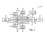
FIG. 1 illustrates a block diagram of an embodiment of agas turbine system 10, which may utilize an aerodynamic feed cap in accordance with present embodiments. Thesystem 10 includes acompressor 12,turbine combustors 14, and aturbine 16. Theturbine combustors 14 includefuel nozzles 18 which route a liquid fuel and/or gas fuel, such as natural gas or syngas, into theturbine combustors 14. As shown, eachturbine combustor 14 may havemultiple fuel nozzles 18. More specifically, theturbine combustors 14 may each include a primary fuel injection system havingprimary fuel nozzles 20 and a secondary fuel injection system havingsecondary fuel nozzles 22. As described in detail below, eachturbine combustor 14 may also include a feed cap configured to reduce undesirable no-flow, low-flow, recirculation, or other undesirable air flow situations. Furthermore, the aerodynamic feed cap of eachturbine combustor 14 may mitigate acoustic waves and suppress pressure fluctuations (i.e., reduce the occurrence of dynamics) in theturbine combustor 14. Indeed, such a feed cap design may be desirable to mitigate the possibility of retaining a combustible mixture of fuel and air in a recirculation zone, such as a low velocity region. For example, in a recirculation zone, a flame can hold in this region and/or travel upstream to this region, which may be undesirable. - The
turbine combustors 14 ignite and combust an air-fuel mixture, and then pass hot pressurized combustion gasses 24 (e.g., exhaust) into theturbine 16. Turbine blades are coupled to ashaft 26, which is also coupled to several other components throughout theturbine system 10. As thecombustion gases 24 pass through the turbine blades in theturbine 16, theturbine 16 is driven into rotation, which causes theshaft 26 to rotate. Eventually, thecombustion gases 24 exit theturbine system 10 via anexhaust outlet 28. Further, theshaft 26 may be coupled to aload 30, which is powered via rotation of theshaft 26. For example, theload 30 may be any suitable device that may generate power via the rotational output of theturbine system 10, such as an electrical generator, a propeller of an airplane, and so forth. - Compressor blades are included as components of the
compressor 12. The blades within thecompressor 12 are coupled to theshaft 26, and will rotate as theshaft 26 is driven to rotate by theturbine 16, as described above. The rotation of the blades within thecompressor 12 compress air from anair intake 32 intopressurized air 34. Thepressurized air 34 is then fed into thefuel nozzles 18 of theturbine combustors 14. The fuel nozzles 18 mix thepressurized air 34 and fuel to produce a suitable mixture ratio for combustion (e.g., a combustion that causes the fuel to more completely burn) so as not to waste fuel or cause excess emissions. As discussed below, the compressed air may pass through and/or around the feed cap in each combustor 14 upstream from fuel injection. -
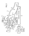
FIG. 2 is a schematic of an embodiment of one of theturbine combustors 14 ofFIG. 1 , illustrating afeed cap 50 disposed within ahead end 52 of theturbine combustor 14 and about asingle fuel nozzle 20. As described above, thecompressor 12 receives air from theair intake 32, compresses the air, and produces the flow ofpressurized air 34 for use in the combustion process within theturbine combustor 14. As shown in the illustrated embodiment, thepressurized air 34 is received by acompressor discharge 54 that is operatively coupled to theturbine combustor 14. As indicated byarrows 56, thepressurized air 34 flows from thecompressor discharge 54 toward thehead end 52 of theturbine combustor 14. More specifically, thepressurized air 34 flows through anannulus 60 between aliner 62 and aflow sleeve 64 of theturbine combustor 14 to reach thehead end 52. - In certain embodiments, the
head end 52 includes anend plate 66 that may support theprimary fuel nozzles 20 depicted inFIG. 1 . In the illustrated embodiment, thehead end 52 has the singleprimary fuel nozzle 20 and associatedfeed cap 50. However, as discussed below, thehead end 52 may include a plurality offuel nozzles 20, with one or more feed caps 50 surrounding thefuel nozzles 20. In accordance with one embodiment, asingle feed cap 50 may surround a plurality of thefuel nozzles 20, such as between 2 and 10 fuel nozzles (e.g., between 2 and 8 or 4 and 6 fuel nozzles). - A fuel supply provides
fuel 68 to theprimary fuel nozzle 20. Additionally, anair flow path 72 delivers thepressurized air 34 from theannulus 60 of theturbine combustor 14 through theprimary fuel nozzle 20. Theprimary fuel nozzle 20 combines thepressurized air 34 with thefuel 68 provided by theprimary fuel supply 68 to form an fuel-air mixture. Specifically, thefuel 68 may be injected into theair flow path 72 by a plurality ofswirl vanes 74 and, in some embodiments, additionally by one or morequaternary fuel injectors 97. The fuel-air mixture flows from theair flow path 72 into acombustion chamber 76 where the fuel-air mixture is ignited and combusted to form combustion gases (e.g., exhaust). The combustion gases flow in adirection 78 toward atransition piece 80 of theturbine combustor 14. The combustion gases pass through thetransition piece 80, as indicated byarrow 82, toward theturbine 16, where the combustion gases drive the rotation of the blades within theturbine 16. - As noted above, the
turbine combustor 14 includes regions where combustion is desired, such as thecombustion chamber 76, and regions where combustion is undesirable, such as ahead end chamber 84 disposed between theend plate 66 and adivider plate 86 separating thehead end 52 from thecombustion chamber 76. Combustion (e.g., flashback and/or flame holding) within thehead end chamber 84 may be a result of turbulent air flow and fuel-air pockets along theair flow path 72, where the flow recirculates and/or has a low or no velocity in an upstream region, such as upstream of a combustion chamber and/or upstream of a fuel injector (e.g., fuel injector 20), and downstream ofquaternary fuel injectors 97. Thus, in accordance with the present disclosure, it is now recognized that these and other undesirable flow conditions may be mitigated, at least in part, by providing anaerodynamic back plate 88 connecting anouter wall 90 of thefeed cap 50 with anouter shell 92 of thefuel nozzle 20. Specifically, as discussed in detail below, theback plate 88 connects theouter shell 92 of thefuel nozzle 20 with theouter wall 90 of thefeed cap 50 in such a way that thepressurized air 34 is able to flow along theair flow path 72 without encountering substantial turbulence or pockets of low flow or no flow. Further, the configuration of theback plate 88 may also help reduce the occurrence of pressure waves, acoustic waves, and other oscillations referred to as combustion dynamics, produced by the combustion process. Combustion dynamics may cause performance degradation, structural stresses, and mechanical or thermal fatigue in the turbine combustor 14 (e.g., within the head end chamber 84). - The
back plate 88, theouter wall 90 of thefeed cap 50, theouter shell 92 of thefuel nozzle 20, and thedivider plate 86 together define a closed volume orchamber 94. Thechamber 94, as illustrated, receives an influx of preconditionedair 96 from the set ofquaternary fuel injectors 97 at a pressure that may be equal to or greater than a pressure of thepressurized air 34 flowing along theair path 72. Therefore, relative to theair path 72 andhead end chamber 84, thechamber 94 may be considered to be a pressurized chamber. Thechamber 94, in some embodiments, receives the preconditionedair 96 at a pressure that is between approximately 1 and 20% higher than the pressure of thepressurized air 34 and/or the air/fuel mixture flowing along theair path 72, such as between approximately 1 and 15%, 1 and 10%, 2 and 8%, 2 and 6%, or 3 and 5% (e.g., approximately 3%, 4%, or 5%) higher. Therefore, thechamber 94 may be sealed to thehead end chamber 84, which may prevent an influx of the fuel and/or the air/fuel mixture from entering thechamber 94. In preventing such an influx, thechamber 94 may reduce the likelihood of premature combustion of the air/fuel mixture within thehead end chamber 84 as a result of no flow or low flow of the air/fuel mixture. As discussed in further detail below, thechamber 94 may also enable cooling of thedivider plate 86 by passing preconditionedair 96 into thecombustion chamber 76. The preconditionedair 96 may be thepressurized air 34, or may be from another air source. As discussed below, thequaternary fuel injectors 97 may also injectfuel 86 into theair path 72 to form a fuel-air mixture. Accordingly, the configuration of theback plate 88, and in particular its manner of connection with theouter wall 90 of thefeed cap 50 and theouter shell 92 of thefuel nozzle 20, reduces the possibility of flame holding and recirculation of the fuel-air mixture. -
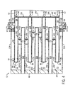
FIG. 3 is a schematic of an embodiment of thehead end 52 of theturbine combustor 14, taken within line 3-3 ofFIG. 2 , illustrating thechamber 94, thequaternary fuel injectors 97, and theprimary fuel nozzle 20 disposed within thehead end chamber 84. As noted, theback plate 88 joins theouter wall 90 of thefeed cap 50 with theouter shell 92 of thefuel nozzle 20. Specifically, theback plate 88 directly connects ahead end terminus 98 of theouter wall 90 with ahead end terminus 100 of theouter shell 92. Theback plate 88 may take on any aerodynamic form, wherein a main portion 102 of theback plate 88 may be curved (e.g., concave or convex), sinuous, angled, or substantially parallel with respect to theend plate 66 and/or thedivider plate 86, as discussed below with respect toFIGS. 5-7 . In certain embodiments, theback plate 88 may extend in a substantially straight line from thehead end terminus 98 to thehead end terminus 100, and may be substantially free of flow-impeding surfaces such as recesses or concave shapes(e.g., with respect to thetermini 98, 100). In one embodiment, theback plate 88 is substantially parallel with respect to theend plate 66 and/or thedivider plate 86. As defined herein, substantially parallel includes configurations where the entirety of the first portion 102 is oriented to within approximately 2° of parallel with respect to either or both of theend plate 66 and thedivider plate 86, accounting for manufacturing tolerances. However, configurations where the main portion 102 is angled with respect to theend plate 66 and/or thedivider plate 86 is also presently contemplated, such as angled to between approximately 2 and 30°, 2 and 20°, 2 and 15°, 3 and 10°, or 4 and 8°. As illustrated, the main portion 102 is substantially parallel with respect to both theend plate 66 and thedivider plate 86, and is rounded at its first and second edges 104, 106 where it connects to theouter wall 90 and theouter shell 92, respectively. In accordance with present embodiments, the first and second edges 104, 106 may assume any edge configuration, including rounded edges, straight edges, beveled edges, protruding edges, or any edge that does not create shear forces on thepressurized air 34. - Indeed, the configuration of the
back plate 88, as discussed herein, facilitates flow of thepressurized air 34 and the fuel-air mixture along theair flow path 72. As mentioned above, theair flow path 72 receives thepressurized air 34 from theannulus 60 of theturbine combustor 14. Additionally, in certain embodiments, thequaternary fuel injectors 97 injectfuel 68 into theflow path 72 to form the fuel-air mixture, which may also flow along theair flow path 72. Theair flow path 72 includes afirst portion 120, asecond portion 122, and athird portion 123. Thefirst portion 120, thesecond portion 122, and thethird portion 123 are operatively coupled. Thefirst portion 120 of theair flow path 72 is defined by anouter wall 124, which may be a head end casing or theflow sleeve 64, and theouter wall 90 of thefeed cap 50. Thesecond portion 122 of theair flow path 72 is defined by theend plate 66 of thehead end chamber 84 and theback plate 88 of thefeed cap 50. Theouter shell 92 and aninner shell 130 of thefuel nozzle 20 define thethird portion 123. In other words, the flow of thepressurized air 34 and/or the fuel-air mixture flows along an outer surface of thepressurized chamber 94 including a first outer surface of thefeed cap 50 disposed around thefuel nozzle 20, an outer surface of theback plate 88, and an outer surface of theouter shell 92 of thefuel nozzle 20. As illustrated, theback plate 88 is disposed at the juncture of the first andsecond portions third portions back plate 88 may facilitate flow of thepressurized air 34 between each portion. - For example, the first edge 104 of the
back plate 88, which couples theback plate 88 with theouter wall 90 of thefeed cap 50, may be rounded so as to prevent turbulent, recirculating, and/or low-velocity flow as thepressurized air 34 and/or fuel-air mixture flows from thefirst portion 120 to thesecond portion 122. Likewise, the second edge 106 of theback plate 88, which couples theback plate 88 with theouter shell 92 of thefuel nozzle 20, may be rounded so as to prevent turbulent, recirculating, and/or low-velocity flow as the pressurized air and/or fuel-air mixture flows from thesecond portion 122 to thethird portion 123. The main portion 102 of theback plate 88 prevents the air and/or fuel-air flow from stalling. In other words, the main portion 102 prevents pockets ofpressurized air 34 and/or the air/fuel mixture from becoming trapped in thesecond portion 122 by enabling continuous flow of thepressurized air 34 and/or the fuel-air mixture. Additionally, the main portion 102 is shaped to prevent areas where a crosswise flow of air is formed in thesecond portion 122. Generally, theback plate 88 will not have any surfaces that create flow shearing, such as protrusions, obstructions, recesses, and so on. Indeed, theouter wall 90, theback plate 88, and theouter shell 92 are configured such that theair path 72 is substantially free of no flow or low flow regions in which a flow of the pressurized air and/or fuel-air mixture is impeded, halted, or otherwise sheared. That is, theback plate 88 may be a substantially smooth, continuous surface. - As indicated by
arrows 132, thepressurized air 34 flows from theannulus 60, first through thefirst portion 120 of theair flow path 72, through thesecond portion 122 of theair flow path 72, and then through thethird portion 123. As noted, thepressurized air 34 may mix with thefuel 68, forming a fuel-air mixture. Therefore, in teh first, second, andthird portions arrows 132 may also represent the fuel-air mixture. Thepressurized air 34 and/or fuel-air mixture also flows around the swirl vanes 74. As discussed above, thefuel 68 is released into thepressurized air 34 through the swirl vanes 74. Specifically, thefuel 68 flows down afuel path 134 within theinner shell 130 of thefuel nozzle 20, as represented by arrows 136. Thefuel 68 passes into theswirl vanes 74 from thefuel path 134, as represented byarrows 138, and exits theswirl vanes 74 throughfuel ports 140 in theswirl vanes 74, as represented byarrows 142. Thefuel 68 mixes with thepressurized air 34 to create an air/fuel mixture. The air/fuel mixture flows downstream, as indicated byarrows 144, toward thecombustion chamber 76. In the illustrated embodiment, thedivider plate 86 includes one ormore openings 146 that operatively join thehead end chamber 84 and thecombustion chamber 76. - As mentioned above, the
head end 52 of theturbine combustor 14 includes thechamber 94, which receives preconditionedair 96. Specifically, the preconditionedair 96 enters thechamber 94 through a preconditionedair inlet 148, while a flow of thefuel 86 enters thefirst portion 120 of theair flow path 72 through a series offuel inlets 149. For example, the preconditionedair 96 may be supplied by thecompressor discharge 54. While the illustrated embodiment shows two preconditionedair inlets 148, other embodiments may include fewer or morepreconditioned air inlets 148. For example, theturbine combustor 14 may have 1, 3, 4, 5, 6, 7, 8, or morepreconditioned air inlets 148. Thechamber 94 receives preconditionedair 96 from the preconditionedair inlet 148 and fills with the preconditionedair 96, as indicated byarrows 150. Additionally, the preconditionedair 96 may be directed towardapertures 152 in thedivider plate 86, as indicated byarrows 154. In certain embodiments, theapertures 152 may be straight or angled holes. The preconditionedair 96 may pass through theapertures 152, thereby cooling thedivider plate 86 and entering thecombustion chamber 76. As noted, the preconditionedair 96 is provided to thechamber 94 at a pressure sufficient to prevent the influx of the fuel-air mixture produced at thefuel nozzle 20 into thechamber 94. That is, the fuel-air mixture may be at a first pressure, the preconditionedair 96 within thechamber 94 may be at a second pressure, and the second pressure may be greater than the first pressure. Again, the preconditionedair 96 may be between approximately 1 and 15%, 1 and 10%, 2 and 8%, 2 and 6%, or 3 and 5% (e.g., approximately 3%, 4%, or 5%) higher than thepressurized air 34 and/or the fuel-air mixture. Additionally, in certain embodiments, the pressure within thechamber 94 may be at a level sufficient to prevent the influx of the combustion products produced within thecombustion chamber 76. -
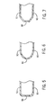
FIG. 4 is a schematic of an embodiment of thehead end 52 of theturbine combustor 14, taken along line 3-3 ofFIG. 2 , illustrating thefeed cap 50 disposed about a plurality offuel nozzles 20. For example, theturbine combustor 14 may include a central fuel nozzle and a plurality of surrounding fuel nozzles (e.g., 2 to 10). In the illustrated embodiment, thefeed cap 50 surrounds first and secondouter fuel nozzles central fuel nozzle 164. In present embodiments, theouter wall 90 of thefeed cap 50 acts as a main wall that surrounds all of the fuel nozzles. Additionally, it should be noted that thefuel nozzles 20 are illustrated in a linear configuration to facilitate discussion, and may be in other configurations, such as in an annular arrangement where thefuel nozzles 20 are disposed in a barrel-like configuration. Accordingly, theouter wall 90 of thefeed cap 50 is illustrated as only being disposed proximate the first and secondouter fuel nozzles feed cap 50 includes a plurality of openings corresponding to each of thefuel nozzles outer shells nozzles - As discussed above with respect to
FIG. 3 , the joining of theouter wall 90 of thefeed cap 50 with theouter shell 92 of thefuel nozzle 20 by theback plate 88 and thedivider plate 86forms chamber 94. In a similar manner, the respectiveouter shells 92 of the first and secondouter fuel nozzles outer shell 166 of thecentral fuel nozzle 164 are joined by theback plate 88 and thedivider plate 86 to form avolume 168. That is, theback plate 88 of thefeed cap 50 joins thehead end termini 100 of theouter shells 92 of the first and secondouter fuel nozzles head end terminus 170 of theouter shell 166 of thecentral fuel nozzle 164. In this way, theair flow path 72 in the area of thecentral fuel nozzle 164 may be substantially free of areas of low flow or no flow. Therefore, the illustrated configuration is adapted to reduce the possibility of undesirable flow situations, such as recirculation flow, low-velocity flow, flame holding, and so on, within thehead end chamber 84. Additionally, like thechamber 94, thevolume 168 may be filled with the preconditionedair 96. - For example, it will be appreciated that the
central fuel nozzle 164 is not disposed proximate theouter wall 90 of thefeed cap 50. Rather, the first and secondouter fuel nozzles central fuel nozzles outer wall 90. Thus, the preconditionedair 96 is not directly injected into thevolume 168. Instead, the preconditionedair 96 is first directly injected into thechamber 94, and flows toward the central region of thehead end 52, which includes thecentral fuel nozzle 164 and thevolume 168. The preconditionedair 96 then fills thevolume 168. Thus, thevolume 168 and thechamber 94 are in direct flow communication, and may have the same pressure. Indeed, thevolume 168 may have a pressure of preconditionedair 96 that is greater than a pressure of an air fuel mixture flowing through thecentral nozzle 164. For example, the pressure of the preconditionedair 96 within thevolume 168 may be between approximately 1 and 15%, 1 and 10%, 2 and 8%, 2 and 6%, or 3 and 5% (e.g., approximately 3%, 4%, or 5%) higher than thepressurized air 34 and/or the fuel-air mixture. - As noted above, the
back plate 88 may take on any aerodynamic form that connects theouter wall 90 of thefeed cap 50 with theouter shell 92 of thefuel nozzle 20. That is, theback plate 88 is configured to maintain sufficient flow along all boundary surfaces so as to prevent recirculation of the fuel-air mixture and/or thepressurized air 34. Examples of such configurations are illustrated inFIGS. 5-7 . Specifically, inFIG. 5 , theback plate 88 may have a generally straight shape that is substantially free of any flow-impeding surfaces. Alternatively, theback plate 88 may be bent and/or angled. For example, as illustrated inFIG. 6 , theback plate 88 may have a curved shape that is convex (i.e., bows outward) with respect to the head end termini of theouter wall 90 and theouter shell 92. Alternatively or additionally, theback plate 88 may be angled, as illustrated inFIG. 7 . InFIG. 7 , theback plate 88 is illustrated as being angled generally along a flow direction of theflow path 72. Indeed, any general shape and configuration of theback plate 88 that is configured to reduce the possibility of flame holding, flashback, low-velocity flow, no flow, and similar undesirable flow conditions, are presently contemplated. - This written description uses examples to disclose the invention, including the best mode, and also to enable any person skilled in the art to practice the invention, including making and using any devices or systems and performing any incorporated methods. The patentable scope of the invention is defined by the claims, and may include other examples that occur to those skilled in the art. Such other examples are intended to be within the scope of the claims if they have structural elements that do not differ from the literal language of the claims, or if they include equivalent structural elements with insubstantial differences from the literal language of the claims.
- Various aspects and embodiments of the present invention are defined by the following numbered clauses:
- 1. A system, comprising:
- a turbine combustor, comprising:
- a combustion chamber;
- a head end chamber separated from the combustion chamber by a divider plate; and
- an air path disposed in the head end chamber and configured to flow a first pressurized air into a fuel nozzle, wherein the air path comprises:
- a first segment disposed between a flow sleeve of the turbine combustor and an outer wall of a feed cap;
- a second segment disposed downstream of the first segment and between a back plate of the feed cap and an end plate of the head end chamber, wherein the second segment is substantially free of any flow-impeding surfaces between the back plate and the end plate; and
- a third segment disposed downstream of the second segment and between inner and outer shells of the fuel nozzle.
- a turbine combustor, comprising:
- 2. The system of clause 1, wherein the air path is configured to receive the first pressurized air at a first pressure from an annulus defined by the flow sleeve and a flow liner of the turbine combustor, and wherein the air path is configured to mix the first pressurized air with a fuel injected by a quaternary fuel injector to produce a pressurized fuel-air mixture at a second pressure.
- 3. The system of any preceding clause, wherein the divider plate, the back plate of the feed cap, the outer wall of the feed cap, and the outer shell of the fuel nozzle form a pressurized chamber configured to receive a flow of a second pressurized air at a third pressure, wherein the third pressure is greater than the second pressure.
- 4. The system of any preceding clause, wherein the second segment of the air path is configured to be substantially free of a crosswise flow of the first pressurized air, wherein the crosswise flow comprises a flow direction oriented crosswise with respect to the end plate of the head end chamber.
Claims (15)
- A system (10), comprising:a turbine combustor (14), comprising:a fuel nozzle (20) comprising an inner shell (130) and an outer shell (92); anda feed cap (50) disposed about the fuel nozzle (20) comprising an outer wall (90) and a back plate (88), wherein the back plate (88) joins respective upstream ends of the outer shell (92) of the fuel nozzle (20) and the outer wall (90) of the feed cap (50);wherein the turbine combustor (14) is configured to flow a first pressurized air via a first air path (72) extending along the outer wall (90) of the feed cap (50), the back plate (88) of the feed cap (50), and into the fuel nozzle (20).
- The system of claim 1, wherein the back plate (88) of the feed cap (50) is configured to maintain flow along the back plate (88) to impede any recirculation of the flow along the back plate (88).
- The system of claim 1 or 2, wherein the back plate (88) excludes any obstructions or recesses between the outer shell (92) and the outer wall (90).
- The system of any of claims 1 to 3, wherein the turbine combustor (14) comprises a combustion chamber (76), a head end chamber (84), and a divider plate (86) separating the combustion chamber (76) from the head end chamber (84), wherein the divider plate (86) and the back plate (88) form two walls of a pressurized chamber (94) surrounding the fuel nozzle (20).
- The system of claim 4, wherein the back plate (88) is oriented substantially parallel with respect to an end plate (66) of the head end chamber (84), and the back plate (88) is rounded at its edges where the back plate (88) merges with the outer wall (90) of the feed cap (50) and the outer shell (92) of the fuel nozzle (20).
- The system of claim 4 or 5, wherein at least a portion of the first air path (72) is defined by the inner (130) and outer shells (92) of the fuel nozzle (20), an end plate (66) of the head end chamber (84), the back plate (88) of the feed cap (50), and the outer wall (90) of the feed cap (50).
- The system of any of claims 4 to 6, wherein the outer wall (90) of the feed cap (50) and the outer shell (92) of the fuel nozzle (20) are each attached to the divider plate (86) to form the pressurized chamber (94).
- The system of claim 7, wherein the turbine combustor (14) is configured to flow the first pressurized air (34) at a first pressure and provide a second pressurized air (96) to the pressurized chamber (94) at a second pressure, wherein the second pressure is greater than the first pressure.
- The system of any preceding claim, wherein the turbine combustor (14) comprises a fuel injector (97) along the air path upstream from the fuel nozzle (20) and the back plate (88).
- The system of any preceding claim, wherein the turbine combustor comprises a divider plate (86) between a combustion chamber (76) and a head end chamber (84), wherein the fuel nozzle (20) is disposed in the head end chamber (84) between an end plate (66) and the divider plate (86), wherein the outer wall (90) of the feed cap (50), the back plate (88) of the feed cap (50), and the outer shell (92) of the fuel nozzle (20) are configured to maintain a sufficient flow along all boundaries to impede combustion in the head end chamber (84).
- The system of claim 4, further comprising:a pressurized chamber (94) disposed in the head end chamber (84) and about the fuel nozzle (20), wherein the pressurized chamber (94) comprises the back plate (88) that is joined to an upstream end of the outer shell (92) of the fuel nozzle (20).
- The system of claim 11, wherein the first air path (72) is configured to flow a first pressurized air (84) along an outer surface of the pressurized chamber (94), and the outer surface of the pressurized chamber (94) comprises a first outer surface of the feed cap (50) disposed around the fuel nozzle (20), a second outer surface of the back plate (88), and a third outer surface of the outer shell (92) of the fuel nozzle (20).
- The system of any preceding claim, the first air path (72) is substantially free of flow impeding surfaces.
- The system of any of claims 11 to 13, wherein the back plate (88) of the pressurized chamber (94) joins a terminal head end (98) of the outer shell (92) of the fuel nozzle (20) and another terminal head end (100) of a feed cap (50) disposed about the fuel nozzle (20).
- The system of any of claims 6 to 14, wherein the end plate (66) ispositioned substantially parallel with respect to the divider plate (86), wherein the back plate (88) comprises a flat wall or a curved wall that is curved toward the end plate (66).
Applications Claiming Priority (1)
| Application Number | Priority Date | Filing Date | Title |
|---|---|---|---|
| US13/448,283 US8966907B2 (en) | 2012-04-16 | 2012-04-16 | Turbine combustor system having aerodynamic feed cap |
Publications (3)
| Publication Number | Publication Date |
|---|---|
| EP2653783A2 true EP2653783A2 (en) | 2013-10-23 |
| EP2653783A3 EP2653783A3 (en) | 2018-03-28 |
| EP2653783B1 EP2653783B1 (en) | 2019-06-12 |
Family
ID=48050552
Family Applications (1)
| Application Number | Title | Priority Date | Filing Date |
|---|---|---|---|
| EP13163005.5A Active EP2653783B1 (en) | 2012-04-16 | 2013-04-09 | Turbine combustor system having aerodynamic feed cap |
Country Status (5)
| Country | Link |
|---|---|
| US (1) | US8966907B2 (en) |
| EP (1) | EP2653783B1 (en) |
| JP (1) | JP6200678B2 (en) |
| CN (1) | CN103375814B (en) |
| RU (1) | RU2013116922A (en) |
Cited By (1)
| Publication number | Priority date | Publication date | Assignee | Title |
|---|---|---|---|---|
| CN106979518A (en) * | 2016-01-19 | 2017-07-25 | 株式会社能率 | Burner shell and the burner apparatus with the burner shell |
Families Citing this family (12)
| Publication number | Priority date | Publication date | Assignee | Title |
|---|---|---|---|---|
| US20120308947A1 (en) * | 2011-06-06 | 2012-12-06 | General Electric Company | Combustor having a pressure feed |
| US20130205799A1 (en) * | 2012-02-15 | 2013-08-15 | Donald Mark Bailey | Outer Fuel Nozzle Inlet Flow Conditioner Interface to End Cap |
| US9631815B2 (en) * | 2012-12-28 | 2017-04-25 | General Electric Company | System and method for a turbine combustor |
| US9297535B2 (en) | 2013-02-25 | 2016-03-29 | General Electric Company | Fuel/air mixing system for fuel nozzle |
| EP2993404B1 (en) * | 2014-09-08 | 2019-03-13 | Ansaldo Energia Switzerland AG | Dilution gas or air mixer for a combustor of a gas turbine |
| US10094566B2 (en) * | 2015-02-04 | 2018-10-09 | General Electric Company | Systems and methods for high volumetric oxidant flow in gas turbine engine with exhaust gas recirculation |
| EP3314167B1 (en) * | 2015-06-24 | 2023-04-05 | General Electric Company | Fuel nozzle assembly having a premix flame stabilizer |
| US10670271B2 (en) * | 2016-09-30 | 2020-06-02 | DOOSAN Heavy Industries Construction Co., LTD | Acoustic dampening liner cap and gas turbine combustor including the same |
| KR102066042B1 (en) * | 2017-10-31 | 2020-01-14 | 두산중공업 주식회사 | Combustor and gas turbine including the same |
| KR102197130B1 (en) * | 2020-01-07 | 2020-12-31 | 두산중공업 주식회사 | Combustor and gas turbine including the same |
| CN115682031B (en) * | 2022-09-29 | 2024-12-06 | 星辰萌想科技(北京)有限公司 | Dual-medium combustion chamber and gas turbine |
| US12429224B1 (en) * | 2024-05-09 | 2025-09-30 | Ge Infrastructure Technology Llc | Axial fuel stage injector with fuel injection in same direction as high-pressure air flow |
Family Cites Families (26)
| Publication number | Priority date | Publication date | Assignee | Title |
|---|---|---|---|---|
| US5339635A (en) * | 1987-09-04 | 1994-08-23 | Hitachi, Ltd. | Gas turbine combustor of the completely premixed combustion type |
| JP2528894B2 (en) * | 1987-09-04 | 1996-08-28 | 株式会社日立製作所 | Gas turbine combustor |
| US5257499A (en) * | 1991-09-23 | 1993-11-02 | General Electric Company | Air staged premixed dry low NOx combustor with venturi modulated flow split |
| JPH06272862A (en) * | 1993-03-18 | 1994-09-27 | Hitachi Ltd | Method and apparatus for mixing fuel into air |
| US5671597A (en) * | 1994-12-22 | 1997-09-30 | United Technologies Corporation | Low nox fuel nozzle assembly |
| US5675971A (en) * | 1996-01-02 | 1997-10-14 | General Electric Company | Dual fuel mixer for gas turbine combustor |
| JPH102558A (en) * | 1996-06-14 | 1998-01-06 | Hitachi Ltd | Fuel nozzle for gas turbine combustor |
| US6178752B1 (en) * | 1998-03-24 | 2001-01-30 | United Technologies Corporation | Durability flame stabilizing fuel injector with impingement and transpiration cooled tip |
| ITMI20012781A1 (en) * | 2001-12-21 | 2003-06-21 | Nuovo Pignone Spa | IMPROVED ASSEMBLY OF PRE-MIXING CHAMBER AND COMBUSTION CHAMBER, LOW POLLUTING EMISSIONS FOR GAS TURBINES WITH FUEL |
| US7134287B2 (en) | 2003-07-10 | 2006-11-14 | General Electric Company | Turbine combustor endcover assembly |
| US6923002B2 (en) | 2003-08-28 | 2005-08-02 | General Electric Company | Combustion liner cap assembly for combustion dynamics reduction |
| US7284378B2 (en) | 2004-06-04 | 2007-10-23 | General Electric Company | Methods and apparatus for low emission gas turbine energy generation |
| US6993916B2 (en) * | 2004-06-08 | 2006-02-07 | General Electric Company | Burner tube and method for mixing air and gas in a gas turbine engine |
| JP2006138566A (en) * | 2004-11-15 | 2006-06-01 | Hitachi Ltd | Gas turbine combustor and liquid fuel injection nozzle thereof |
| US7540152B2 (en) * | 2006-02-27 | 2009-06-02 | Mitsubishi Heavy Industries, Ltd. | Combustor |
| US7523614B2 (en) * | 2006-02-27 | 2009-04-28 | Mitsubishi Heavy Industries, Ltd. | Combustor |
| US9121609B2 (en) | 2008-10-14 | 2015-09-01 | General Electric Company | Method and apparatus for introducing diluent flow into a combustor |
| US8161750B2 (en) * | 2009-01-16 | 2012-04-24 | General Electric Company | Fuel nozzle for a turbomachine |
| US8607568B2 (en) | 2009-05-14 | 2013-12-17 | General Electric Company | Dry low NOx combustion system with pre-mixed direct-injection secondary fuel nozzle |
| US8141363B2 (en) | 2009-10-08 | 2012-03-27 | General Electric Company | Apparatus and method for cooling nozzles |
| US8276385B2 (en) * | 2009-10-08 | 2012-10-02 | General Electric Company | Staged multi-tube premixing injector |
| US8371123B2 (en) * | 2009-10-28 | 2013-02-12 | General Electric Company | Apparatus for conditioning airflow through a nozzle |
| US8381526B2 (en) | 2010-02-15 | 2013-02-26 | General Electric Company | Systems and methods of providing high pressure air to a head end of a combustor |
| US8123150B2 (en) | 2010-03-30 | 2012-02-28 | General Electric Company | Variable area fuel nozzle |
| US8572979B2 (en) * | 2010-06-24 | 2013-11-05 | United Technologies Corporation | Gas turbine combustor liner cap assembly |
| US8281596B1 (en) * | 2011-05-16 | 2012-10-09 | General Electric Company | Combustor assembly for a turbomachine |
-
2012
- 2012-04-16 US US13/448,283 patent/US8966907B2/en active Active
-
2013
- 2013-04-09 EP EP13163005.5A patent/EP2653783B1/en active Active
- 2013-04-11 JP JP2013082583A patent/JP6200678B2/en active Active
- 2013-04-15 RU RU2013116922/06A patent/RU2013116922A/en not_active Application Discontinuation
- 2013-04-16 CN CN201310131857.2A patent/CN103375814B/en active Active
Cited By (1)
| Publication number | Priority date | Publication date | Assignee | Title |
|---|---|---|---|---|
| CN106979518A (en) * | 2016-01-19 | 2017-07-25 | 株式会社能率 | Burner shell and the burner apparatus with the burner shell |
Also Published As
| Publication number | Publication date |
|---|---|
| US8966907B2 (en) | 2015-03-03 |
| EP2653783A3 (en) | 2018-03-28 |
| JP6200678B2 (en) | 2017-09-20 |
| EP2653783B1 (en) | 2019-06-12 |
| JP2013221737A (en) | 2013-10-28 |
| US20130269350A1 (en) | 2013-10-17 |
| RU2013116922A (en) | 2014-10-20 |
| CN103375814B (en) | 2017-04-12 |
| CN103375814A (en) | 2013-10-30 |
Similar Documents
| Publication | Publication Date | Title |
|---|---|---|
| US8966907B2 (en) | Turbine combustor system having aerodynamic feed cap | |
| CN102444911B (en) | There is the burner of poor pre-spraying nozzle fuel injection system | |
| US6786047B2 (en) | Flashback resistant pre-mix burner for a gas turbine combustor | |
| EP2527741B1 (en) | System for flow control in gas turbine engine | |
| EP1923637B1 (en) | Triple annular counter rotating swirler | |
| US8381532B2 (en) | Bled diffuser fed secondary combustion system for gas turbines | |
| EP2527742B1 (en) | System and method for flow control in gas turbine engine | |
| KR101774630B1 (en) | Tangential annular combustor with premixed fuel and air for use on gas turbine engines | |
| JP2014132214A (en) | Fuel injector for supplying fuel to combustor | |
| EP2664854B1 (en) | Secondary combustion system | |
| EP2664852A2 (en) | Fuel Nozzle Cap | |
| US10458655B2 (en) | Fuel nozzle assembly | |
| JP2010096487A (en) | Vanelet of combustor burner | |
| EP2505921B1 (en) | Combustor crossfire tube having purge holes | |
| EP3425281B1 (en) | Pilot nozzle with inline premixing | |
| US20180340689A1 (en) | Low Profile Axially Staged Fuel Injector | |
| EP2527744B1 (en) | System and method for turbine combustor mounting assembly | |
| US9068750B2 (en) | Combustor with a pre-nozzle mixing cap assembly | |
| CN107191967B (en) | Combustion liner cooling | |
| US11209163B2 (en) | Gas turbine combustor, manufacturing method for gas turbine and gas turbine combustor | |
| US20180245792A1 (en) | Combustion System with Axially Staged Fuel Injection | |
| US10228135B2 (en) | Combustion liner cooling |
Legal Events
| Date | Code | Title | Description |
|---|---|---|---|
| PUAI | Public reference made under article 153(3) epc to a published international application that has entered the european phase |
Free format text: ORIGINAL CODE: 0009012 |
|
| AK | Designated contracting states |
Kind code of ref document: A2 Designated state(s): AL AT BE BG CH CY CZ DE DK EE ES FI FR GB GR HR HU IE IS IT LI LT LU LV MC MK MT NL NO PL PT RO RS SE SI SK SM TR |
|
| AX | Request for extension of the european patent |
Extension state: BA ME |
|
| PUAL | Search report despatched |
Free format text: ORIGINAL CODE: 0009013 |
|
| AK | Designated contracting states |
Kind code of ref document: A3 Designated state(s): AL AT BE BG CH CY CZ DE DK EE ES FI FR GB GR HR HU IE IS IT LI LT LU LV MC MK MT NL NO PL PT RO RS SE SI SK SM TR |
|
| AX | Request for extension of the european patent |
Extension state: BA ME |
|
| RIC1 | Information provided on ipc code assigned before grant |
Ipc: F23R 3/28 20060101AFI20180221BHEP Ipc: F23D 14/64 20060101ALI20180221BHEP |
|
| STAA | Information on the status of an ep patent application or granted ep patent |
Free format text: STATUS: REQUEST FOR EXAMINATION WAS MADE |
|
| 17P | Request for examination filed |
Effective date: 20180928 |
|
| RBV | Designated contracting states (corrected) |
Designated state(s): AL AT BE BG CH CY CZ DE DK EE ES FI FR GB GR HR HU IE IS IT LI LT LU LV MC MK MT NL NO PL PT RO RS SE SI SK SM TR |
|
| GRAP | Despatch of communication of intention to grant a patent |
Free format text: ORIGINAL CODE: EPIDOSNIGR1 |
|
| STAA | Information on the status of an ep patent application or granted ep patent |
Free format text: STATUS: GRANT OF PATENT IS INTENDED |
|
| INTG | Intention to grant announced |
Effective date: 20190129 |
|
| GRAS | Grant fee paid |
Free format text: ORIGINAL CODE: EPIDOSNIGR3 |
|
| GRAA | (expected) grant |
Free format text: ORIGINAL CODE: 0009210 |
|
| STAA | Information on the status of an ep patent application or granted ep patent |
Free format text: STATUS: THE PATENT HAS BEEN GRANTED |
|
| AK | Designated contracting states |
Kind code of ref document: B1 Designated state(s): AL AT BE BG CH CY CZ DE DK EE ES FI FR GB GR HR HU IE IS IT LI LT LU LV MC MK MT NL NO PL PT RO RS SE SI SK SM TR |
|
| REG | Reference to a national code |
Ref country code: GB Ref legal event code: FG4D |
|
| REG | Reference to a national code |
Ref country code: CH Ref legal event code: EP |
|
| REG | Reference to a national code |
Ref country code: AT Ref legal event code: REF Ref document number: 1143047 Country of ref document: AT Kind code of ref document: T Effective date: 20190615 |
|
| REG | Reference to a national code |
Ref country code: DE Ref legal event code: R096 Ref document number: 602013056415 Country of ref document: DE |
|
| REG | Reference to a national code |
Ref country code: IE Ref legal event code: FG4D |
|
| REG | Reference to a national code |
Ref country code: NL Ref legal event code: MP Effective date: 20190612 |
|
| REG | Reference to a national code |
Ref country code: LT Ref legal event code: MG4D |
|
| PG25 | Lapsed in a contracting state [announced via postgrant information from national office to epo] |
Ref country code: ES Free format text: LAPSE BECAUSE OF FAILURE TO SUBMIT A TRANSLATION OF THE DESCRIPTION OR TO PAY THE FEE WITHIN THE PRESCRIBED TIME-LIMIT Effective date: 20190612 Ref country code: AL Free format text: LAPSE BECAUSE OF FAILURE TO SUBMIT A TRANSLATION OF THE DESCRIPTION OR TO PAY THE FEE WITHIN THE PRESCRIBED TIME-LIMIT Effective date: 20190612 Ref country code: FI Free format text: LAPSE BECAUSE OF FAILURE TO SUBMIT A TRANSLATION OF THE DESCRIPTION OR TO PAY THE FEE WITHIN THE PRESCRIBED TIME-LIMIT Effective date: 20190612 Ref country code: LT Free format text: LAPSE BECAUSE OF FAILURE TO SUBMIT A TRANSLATION OF THE DESCRIPTION OR TO PAY THE FEE WITHIN THE PRESCRIBED TIME-LIMIT Effective date: 20190612 Ref country code: HR Free format text: LAPSE BECAUSE OF FAILURE TO SUBMIT A TRANSLATION OF THE DESCRIPTION OR TO PAY THE FEE WITHIN THE PRESCRIBED TIME-LIMIT Effective date: 20190612 Ref country code: SE Free format text: LAPSE BECAUSE OF FAILURE TO SUBMIT A TRANSLATION OF THE DESCRIPTION OR TO PAY THE FEE WITHIN THE PRESCRIBED TIME-LIMIT Effective date: 20190612 Ref country code: NO Free format text: LAPSE BECAUSE OF FAILURE TO SUBMIT A TRANSLATION OF THE DESCRIPTION OR TO PAY THE FEE WITHIN THE PRESCRIBED TIME-LIMIT Effective date: 20190912 |
|
| PG25 | Lapsed in a contracting state [announced via postgrant information from national office to epo] |
Ref country code: RS Free format text: LAPSE BECAUSE OF FAILURE TO SUBMIT A TRANSLATION OF THE DESCRIPTION OR TO PAY THE FEE WITHIN THE PRESCRIBED TIME-LIMIT Effective date: 20190612 Ref country code: LV Free format text: LAPSE BECAUSE OF FAILURE TO SUBMIT A TRANSLATION OF THE DESCRIPTION OR TO PAY THE FEE WITHIN THE PRESCRIBED TIME-LIMIT Effective date: 20190612 Ref country code: GR Free format text: LAPSE BECAUSE OF FAILURE TO SUBMIT A TRANSLATION OF THE DESCRIPTION OR TO PAY THE FEE WITHIN THE PRESCRIBED TIME-LIMIT Effective date: 20190913 Ref country code: BG Free format text: LAPSE BECAUSE OF FAILURE TO SUBMIT A TRANSLATION OF THE DESCRIPTION OR TO PAY THE FEE WITHIN THE PRESCRIBED TIME-LIMIT Effective date: 20190912 |
|
| REG | Reference to a national code |
Ref country code: AT Ref legal event code: MK05 Ref document number: 1143047 Country of ref document: AT Kind code of ref document: T Effective date: 20190612 |
|
| PG25 | Lapsed in a contracting state [announced via postgrant information from national office to epo] |
Ref country code: AT Free format text: LAPSE BECAUSE OF FAILURE TO SUBMIT A TRANSLATION OF THE DESCRIPTION OR TO PAY THE FEE WITHIN THE PRESCRIBED TIME-LIMIT Effective date: 20190612 Ref country code: PT Free format text: LAPSE BECAUSE OF FAILURE TO SUBMIT A TRANSLATION OF THE DESCRIPTION OR TO PAY THE FEE WITHIN THE PRESCRIBED TIME-LIMIT Effective date: 20191014 Ref country code: NL Free format text: LAPSE BECAUSE OF FAILURE TO SUBMIT A TRANSLATION OF THE DESCRIPTION OR TO PAY THE FEE WITHIN THE PRESCRIBED TIME-LIMIT Effective date: 20190612 Ref country code: CZ Free format text: LAPSE BECAUSE OF FAILURE TO SUBMIT A TRANSLATION OF THE DESCRIPTION OR TO PAY THE FEE WITHIN THE PRESCRIBED TIME-LIMIT Effective date: 20190612 Ref country code: SK Free format text: LAPSE BECAUSE OF FAILURE TO SUBMIT A TRANSLATION OF THE DESCRIPTION OR TO PAY THE FEE WITHIN THE PRESCRIBED TIME-LIMIT Effective date: 20190612 Ref country code: RO Free format text: LAPSE BECAUSE OF FAILURE TO SUBMIT A TRANSLATION OF THE DESCRIPTION OR TO PAY THE FEE WITHIN THE PRESCRIBED TIME-LIMIT Effective date: 20190612 Ref country code: EE Free format text: LAPSE BECAUSE OF FAILURE TO SUBMIT A TRANSLATION OF THE DESCRIPTION OR TO PAY THE FEE WITHIN THE PRESCRIBED TIME-LIMIT Effective date: 20190612 |
|
| PG25 | Lapsed in a contracting state [announced via postgrant information from national office to epo] |
Ref country code: IS Free format text: LAPSE BECAUSE OF FAILURE TO SUBMIT A TRANSLATION OF THE DESCRIPTION OR TO PAY THE FEE WITHIN THE PRESCRIBED TIME-LIMIT Effective date: 20191012 Ref country code: SM Free format text: LAPSE BECAUSE OF FAILURE TO SUBMIT A TRANSLATION OF THE DESCRIPTION OR TO PAY THE FEE WITHIN THE PRESCRIBED TIME-LIMIT Effective date: 20190612 |
|
| REG | Reference to a national code |
Ref country code: DE Ref legal event code: R097 Ref document number: 602013056415 Country of ref document: DE |
|
| PG25 | Lapsed in a contracting state [announced via postgrant information from national office to epo] |
Ref country code: TR Free format text: LAPSE BECAUSE OF FAILURE TO SUBMIT A TRANSLATION OF THE DESCRIPTION OR TO PAY THE FEE WITHIN THE PRESCRIBED TIME-LIMIT Effective date: 20190612 |
|
| PLBE | No opposition filed within time limit |
Free format text: ORIGINAL CODE: 0009261 |
|
| STAA | Information on the status of an ep patent application or granted ep patent |
Free format text: STATUS: NO OPPOSITION FILED WITHIN TIME LIMIT |
|
| PG25 | Lapsed in a contracting state [announced via postgrant information from national office to epo] |
Ref country code: DK Free format text: LAPSE BECAUSE OF FAILURE TO SUBMIT A TRANSLATION OF THE DESCRIPTION OR TO PAY THE FEE WITHIN THE PRESCRIBED TIME-LIMIT Effective date: 20190612 Ref country code: PL Free format text: LAPSE BECAUSE OF FAILURE TO SUBMIT A TRANSLATION OF THE DESCRIPTION OR TO PAY THE FEE WITHIN THE PRESCRIBED TIME-LIMIT Effective date: 20190612 |
|
| 26N | No opposition filed |
Effective date: 20200313 |
|
| PG25 | Lapsed in a contracting state [announced via postgrant information from national office to epo] |
Ref country code: SI Free format text: LAPSE BECAUSE OF FAILURE TO SUBMIT A TRANSLATION OF THE DESCRIPTION OR TO PAY THE FEE WITHIN THE PRESCRIBED TIME-LIMIT Effective date: 20190612 Ref country code: IS Free format text: LAPSE BECAUSE OF FAILURE TO SUBMIT A TRANSLATION OF THE DESCRIPTION OR TO PAY THE FEE WITHIN THE PRESCRIBED TIME-LIMIT Effective date: 20200224 |
|
| PG2D | Information on lapse in contracting state deleted |
Ref country code: IS |
|
| PG25 | Lapsed in a contracting state [announced via postgrant information from national office to epo] |
Ref country code: MC Free format text: LAPSE BECAUSE OF FAILURE TO SUBMIT A TRANSLATION OF THE DESCRIPTION OR TO PAY THE FEE WITHIN THE PRESCRIBED TIME-LIMIT Effective date: 20190612 |
|
| REG | Reference to a national code |
Ref country code: CH Ref legal event code: PL |
|
| PG25 | Lapsed in a contracting state [announced via postgrant information from national office to epo] |
Ref country code: LU Free format text: LAPSE BECAUSE OF NON-PAYMENT OF DUE FEES Effective date: 20200409 Ref country code: CH Free format text: LAPSE BECAUSE OF NON-PAYMENT OF DUE FEES Effective date: 20200430 Ref country code: LI Free format text: LAPSE BECAUSE OF NON-PAYMENT OF DUE FEES Effective date: 20200430 |
|
| REG | Reference to a national code |
Ref country code: BE Ref legal event code: MM Effective date: 20200430 |
|
| PG25 | Lapsed in a contracting state [announced via postgrant information from national office to epo] |
Ref country code: BE Free format text: LAPSE BECAUSE OF NON-PAYMENT OF DUE FEES Effective date: 20200430 |
|
| GBPC | Gb: european patent ceased through non-payment of renewal fee |
Effective date: 20200409 |
|
| PG25 | Lapsed in a contracting state [announced via postgrant information from national office to epo] |
Ref country code: IE Free format text: LAPSE BECAUSE OF NON-PAYMENT OF DUE FEES Effective date: 20200409 Ref country code: GB Free format text: LAPSE BECAUSE OF NON-PAYMENT OF DUE FEES Effective date: 20200409 |
|
| PGFP | Annual fee paid to national office [announced via postgrant information from national office to epo] |
Ref country code: IT Payment date: 20210323 Year of fee payment: 9 Ref country code: FR Payment date: 20210323 Year of fee payment: 9 |
|
| PG25 | Lapsed in a contracting state [announced via postgrant information from national office to epo] |
Ref country code: MT Free format text: LAPSE BECAUSE OF FAILURE TO SUBMIT A TRANSLATION OF THE DESCRIPTION OR TO PAY THE FEE WITHIN THE PRESCRIBED TIME-LIMIT Effective date: 20190612 Ref country code: CY Free format text: LAPSE BECAUSE OF FAILURE TO SUBMIT A TRANSLATION OF THE DESCRIPTION OR TO PAY THE FEE WITHIN THE PRESCRIBED TIME-LIMIT Effective date: 20190612 |
|
| PG25 | Lapsed in a contracting state [announced via postgrant information from national office to epo] |
Ref country code: MK Free format text: LAPSE BECAUSE OF FAILURE TO SUBMIT A TRANSLATION OF THE DESCRIPTION OR TO PAY THE FEE WITHIN THE PRESCRIBED TIME-LIMIT Effective date: 20190612 |
|
| PG25 | Lapsed in a contracting state [announced via postgrant information from national office to epo] |
Ref country code: FR Free format text: LAPSE BECAUSE OF NON-PAYMENT OF DUE FEES Effective date: 20220430 |
|
| PG25 | Lapsed in a contracting state [announced via postgrant information from national office to epo] |
Ref country code: IT Free format text: LAPSE BECAUSE OF NON-PAYMENT OF DUE FEES Effective date: 20220409 |
|
| P01 | Opt-out of the competence of the unified patent court (upc) registered |
Effective date: 20230522 |
|
| REG | Reference to a national code |
Ref country code: DE Ref legal event code: R082 Ref document number: 602013056415 Country of ref document: DE Ref country code: DE Ref legal event code: R081 Ref document number: 602013056415 Country of ref document: DE Owner name: GENERAL ELECTRIC TECHNOLOGY GMBH, CH Free format text: FORMER OWNER: GENERAL ELECTRIC COMPANY, SCHENECTADY, NY, US |
|
| PGFP | Annual fee paid to national office [announced via postgrant information from national office to epo] |
Ref country code: DE Payment date: 20250319 Year of fee payment: 13 |