EP2653778A1 - Rückbeleuchtungsanordnung und Anzeigevorrichtung damit - Google Patents
Rückbeleuchtungsanordnung und Anzeigevorrichtung damit Download PDFInfo
- Publication number
- EP2653778A1 EP2653778A1 EP12184413.8A EP12184413A EP2653778A1 EP 2653778 A1 EP2653778 A1 EP 2653778A1 EP 12184413 A EP12184413 A EP 12184413A EP 2653778 A1 EP2653778 A1 EP 2653778A1
- Authority
- EP
- European Patent Office
- Prior art keywords
- light
- light guide
- backlight assembly
- reflector
- light source
- Prior art date
- Legal status (The legal status is an assumption and is not a legal conclusion. Google has not performed a legal analysis and makes no representation as to the accuracy of the status listed.)
- Withdrawn
Links
- 230000003287 optical effect Effects 0.000 claims abstract description 46
- 239000012780 transparent material Substances 0.000 claims description 2
- 239000000758 substrate Substances 0.000 description 8
- 230000003247 decreasing effect Effects 0.000 description 5
- 230000007423 decrease Effects 0.000 description 4
- 238000005286 illumination Methods 0.000 description 4
- 238000009792 diffusion process Methods 0.000 description 3
- 230000003252 repetitive effect Effects 0.000 description 3
- 230000004048 modification Effects 0.000 description 2
- 238000012986 modification Methods 0.000 description 2
- 229920003229 poly(methyl methacrylate) Polymers 0.000 description 2
- 239000004926 polymethyl methacrylate Substances 0.000 description 2
- 239000004417 polycarbonate Substances 0.000 description 1
- 229920000515 polycarbonate Polymers 0.000 description 1
- 230000001681 protective effect Effects 0.000 description 1
Images




Classifications
-
- G—PHYSICS
- G02—OPTICS
- G02B—OPTICAL ELEMENTS, SYSTEMS OR APPARATUS
- G02B6/00—Light guides; Structural details of arrangements comprising light guides and other optical elements, e.g. couplings
- G02B6/0001—Light guides; Structural details of arrangements comprising light guides and other optical elements, e.g. couplings specially adapted for lighting devices or systems
- G02B6/0011—Light guides; Structural details of arrangements comprising light guides and other optical elements, e.g. couplings specially adapted for lighting devices or systems the light guides being planar or of plate-like form
- G02B6/0013—Means for improving the coupling-in of light from the light source into the light guide
- G02B6/0023—Means for improving the coupling-in of light from the light source into the light guide provided by one optical element, or plurality thereof, placed between the light guide and the light source, or around the light source
-
- G—PHYSICS
- G02—OPTICS
- G02F—OPTICAL DEVICES OR ARRANGEMENTS FOR THE CONTROL OF LIGHT BY MODIFICATION OF THE OPTICAL PROPERTIES OF THE MEDIA OF THE ELEMENTS INVOLVED THEREIN; NON-LINEAR OPTICS; FREQUENCY-CHANGING OF LIGHT; OPTICAL LOGIC ELEMENTS; OPTICAL ANALOGUE/DIGITAL CONVERTERS
- G02F1/00—Devices or arrangements for the control of the intensity, colour, phase, polarisation or direction of light arriving from an independent light source, e.g. switching, gating or modulating; Non-linear optics
- G02F1/01—Devices or arrangements for the control of the intensity, colour, phase, polarisation or direction of light arriving from an independent light source, e.g. switching, gating or modulating; Non-linear optics for the control of the intensity, phase, polarisation or colour
- G02F1/13—Devices or arrangements for the control of the intensity, colour, phase, polarisation or direction of light arriving from an independent light source, e.g. switching, gating or modulating; Non-linear optics for the control of the intensity, phase, polarisation or colour based on liquid crystals, e.g. single liquid crystal display cells
- G02F1/133—Constructional arrangements; Operation of liquid crystal cells; Circuit arrangements
- G02F1/1333—Constructional arrangements; Manufacturing methods
- G02F1/1335—Structural association of cells with optical devices, e.g. polarisers or reflectors
-
- G—PHYSICS
- G02—OPTICS
- G02B—OPTICAL ELEMENTS, SYSTEMS OR APPARATUS
- G02B6/00—Light guides; Structural details of arrangements comprising light guides and other optical elements, e.g. couplings
- G02B6/0001—Light guides; Structural details of arrangements comprising light guides and other optical elements, e.g. couplings specially adapted for lighting devices or systems
- G02B6/0096—Light guides; Structural details of arrangements comprising light guides and other optical elements, e.g. couplings specially adapted for lighting devices or systems the lights guides being of the hollow type
Definitions
- Exemplary embodiments of the present invention relate to a backlight assembly and a display apparatus having the backlight assembly.
- a display apparatus includes a backlight assembly and a display panel.
- the backlight assembly emits light, and the display panel displays an image using the light from the backlight assembly.
- a light source may be disposed at a side portion of the backlight assembly, which is called as an edge-illumination type backlight assembly, to decrease the thickness of a display apparatus.
- the edge-illumination type backlight assembly includes a light guide plate and a reflective plate.
- the light guide plate guides the light from the light source disposed at the side of the light guide plate.
- the reflective plate is disposed under the light guide plate and reflects the light to the display panel.
- a newly developed structure of the display apparatus does not include the light guide plate, to decrease the weight of a display apparatus and maintain a uniformity of luminance.
- a light emitting diode LED
- the light source which is a point light source providing the light to all directions
- a light-emitting direction of the LED should be focused onto the display panel, to increase the uniformity of luminance.
- Exemplary embodiments of the present invention provide a backlight assembly having increased luminance uniformity.
- Exemplary embodiments of the present invention also provide a display apparatus including the backlight assembly.
- An exemplary embodiment of the backlight assembly includes a light source, a light guide, a first reflector, and an optical unit.
- the light guide is disposed adjacent to the light source, extends substantially parallel with a longitudinal direction of the light source, and refracts light emitted from the light source.
- the first reflector is disposed under the light guide, and reflects the refracted light toward the optical unit.
- the optical unit is disposed over the first reflector such that an empty space is formed between the optical unit and the first reflector.
- Exemplary embodiments of the present invention provide a display apparatus that includes a display panel, a mold frame, a backlight assembly and a container.
- the display panel displays an image using light.
- the mold frame supports the display panel.
- the backlight assembly is disposed under the display panel and provides the light to the display panel.
- the container is disposed under the backlight assembly, and receives the display panel, the mold frame and the backlight assembly.
- the backlight assembly includes a light source, a light guide, a first reflector and an optical unit.
- the light source emits light.
- the light guide is disposed adjacent to the light source, extends substantially parallel with a longitudinal direction of the light source, and refracts the light from the light source.
- the first reflector is disposed under the light guide, and reflects the light refracted from the light source toward an upper direction.
- the optical unit is disposed over the first reflector so that a vacant space is formed between the optical unit and the first reflector.
- the light guide is disposed adjacent to the light source and refracts the light from the light source, and thus an angle of a light-emitting direction of the light source may be decreased.
- luminance of the light provided to the display panel may be more uniform.
- the angle of the light-emitting direction is decreased, and thus, the light is uniformly provided to the first reflector.
- the luminance of the light provided to the display panel may be more uniform.
- a distance between the light source and the light guide, a shape of the light guide, and so on, may be changed to change a focal distance of the light passing through the light guide.
- the luminance may be adjusted based on the structure and the size of the display apparatus.
- the second reflector is disposed between the light guide and the optical to block the light from passing through the light guide and being radiated upward. Thus, hot-spots may be prevented.
- the display apparatus may have improved structural stability.
- the light guide is formed at an inner portion of the light source, and thus, the luminance may be more uniform, without increasing the thickness of a bezel.
- both ends of the light guide are fixed by the mold frame, the container, or the cover portion.
- an additional fixing element may be omitted.
- the display apparatus may have improved structural stability due to a simplified fixing element.
- FIG. 1 is an exploded perspective view illustrating a display apparatus according to an exemplary embodiment of the present invention.
- FIG. 2 is a cross-sectional view taken along a line I-I' in FIG. 1 .
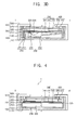
- FIG. 3A , 3B , 3C and 3D are cross-sectional views illustrating examples of a light guide of FIG. 1 .
- FIG. 4 is a cross-sectional view taken along a line II-II' in FIG. 1 .
- FIG. 5 is an exploded perspective view illustrating a display apparatus according to an exemplary embodiment of the present invention.
- FIG. 6 is a cross-sectional view taken along a line III-III' in FIG. 5 .
- FIG. 7 is an exploded perspective view illustrating a display apparatus according to an exemplary embodiment of the present invention.
- FIG. 8 is a cross-sectional view taken along a line IV-IV' in FIG. 7 .
- FIG. 9 is a cross-sectional view illustrating a display apparatus according to an exemplary embodiment of the present invention.
- FIG. 1 is an exploded perspective view illustrating a display apparatus 1 according to an exemplary embodiment of the present invention.
- FIG. 2 is a cross-sectional view taken along a line I-I' in FIG. 1 .
- the display apparatus 1 includes a container 100, a backlight assembly 200, a mold frame 300, a display panel 400, and a cover 500.
- the container 100 includes a bottom plate 110 and a sidewall 120.
- the sidewall 120 extends from the bottom plate 110 and at least partially defines a space with the bottom plate 110.
- the container 100 receives the backlight assembly 200, the mold frame 300, and the display panel 400 in the space.
- the space has a rectangular shape, but is not limited thereto.
- the backlight assembly 200 is received by the container 100, is disposed under the display panel 400, and provides light to the display panel 400. A detailed description of the backlight assembly 200 will be provided later.
- the mold frame 300 has a frame shape and includes a first opening 330.
- the mold frame 300 includes a side portion 310 forming the frame shape, and an extension 320 extending from the side portion 310 toward the first opening 330.
- the extension 320 supports the display panel 400.
- the mold frame 300 is received by the container 100.
- An optical unit 240 is disposed on a lower surface of the extension 320. The light from the backlight assembly 200 passes through the first opening 330 and is provided to the display panel 400.
- the display panel 400 includes a first substrate 410 and is disposed on an opposing second substrate 420.
- the display panel 400 displays an image using the light provided by the backlight assembly 200.
- the cover 500 includes a side cover 510 and an upper cover 520.
- the side cover 510 has a frame shape and includes a second opening 530.
- the upper cover 520 extends from the side cover 510 toward the second opening 530, and partially covers an upper portion of the display panel 400.
- the image from the display panel 500 is provided through the second opening 530.
- the backlight assembly 200 includes a light source 210, a light guide 220, a first reflector 230, and an optical unit 240, and may further include a second reflector 225.
- the light source 210 includes a base substrate 211 and point light sources 212 mounted on the base substrate 211.
- the point light sources 212 may be light emitting diodes (LEDs).
- the base substrate 211 may be an LED printed circuit board (PCB) to drive the LED.
- the base substrate 211 is mounted on the side portion 310 of the mold frame 300, as illustrated in FIG. 2 , but alternatively may be mounted on the bottom plate 110 of the container 100.
- the light source 210 longitudinally extends along the side portion 310 of the mold frame 300.
- the point light sources 212 are disposed along the side portion 310.
- the point light sources 212 are spaced apart from each other by a constant distance.
- the light guide 220 is disposed adjacent to the light source 210, and extends substantially parallel with the longitudinal direction of the light source 210. Thus, the light guide 220 extends substantially parallel with the side portion 310 of the mold frame 300.
- the light guide 220 refracts the light emitted from the light source 212.
- the light emitted from the point light source 212 is radiated in multiple directions.
- the light is scattered, which means that the light has 'a relatively larger angle of a light-emitting direction'.
- the light from the point light source 212 disposed at the edge should be provided to an entire surface of the display panel uniformly.
- the light is emitted from the point light source 212 in multiple directions and should be controlled to radiate more linearly.
- the angle of the direction of the light emitted from the point light source should be reduced.
- the light guide 220 refracts the light emitted from the point light source 212, and thus the angle of the direction of the light may be narrowed.
- the light passing through the light guide 220 advances to relatively farther positions with high luminance, and thus the luminance of the light from the display panel 400 may be more uniform.
- the light refracted by the light guide 220 advances with a focal distance F1
- the focal distance F1 may be controlled by changing a distance between the light source 210 and the light guide 220.
- the distance between the light source 210 and the light guide is controlled considering a size and an inner structure of the display apparatus.
- the luminance of the light provided to the display panel may be improved.
- the light guide 220 is generally cylindrical and has a circular width-wise cross-section.
- the light guide 220 may include a transparent material such as polymethylmethacrylate (PMMA) or polycarbonate (PC).
- PMMA polymethylmethacrylate
- PC polycarbonate
- the first reflector 230 is disposed on a lower surface of the light guide 220, and reflects the light refracted by the light guide 220 toward the display panel 400, which is disposed over the first reflector 230.
- the first reflector 230 includes a first reflective surface 231 and a second reflective surface 232 extending from the first reflective surface 231.
- the first reflective surface 231 makes contact with the light guide 220, and extends substantially parallel with an extending direction of the bottom plate 110 of the container 100. Thus, the first reflective surface 231 and the light guide 200 may be attached with each other more strongly.
- the second reflective surface 232 obliquely extends with respect to the bottom surface 110 toward the optical unit 240. For example, as the second reflective surface 232 extends away from the light guide 220, the second reflective surface 232 becomes closer to the optical unit 240. Since the luminance of the light decreases as the distance from the light guide 220 increases, the second reflective surface 232 is inclined to enhance the luminance of the light provided to the display panel 400. Thus, the light may be more uniformly applied to the optical unit 240.
- a diffusive ink may be uniformly formed on the first and second reflective surfaces 231 and 232 of the first reflector 230.
- the reflectiveness of the light and the diffusion of the light incident into the first reflector 230 may be enhanced.
- the optical unit 240 is disposed over the first reflector 230, and a vacant space is formed between the optical unit 240 and the first reflector 230.
- the light guide plate is omitted between the first reflector 230 and the optical unit 240, and thus the vacant space is formed between the first reflector 230 and the optical unit 240, which is called as an air guide structure.
- the angle of the direction of the light emitted from the light source 210 should be reduced using the light guide 220.
- the optical unit 240 includes a protective sheet 241, a prism sheet 242, and a diffusive sheet 243, to enhance quality of the light provided to the display panel 400.
- the optical unit 240 is supported by an upper surface of the light guide 220.
- a lower surface of the light guide 220 makes contact with the first reflector 230, and the upper surface of the light guide 220 makes contact with the optical unit 240 to support the optical unit 240.
- an additional supporting element may be omitted and thus the display apparatus 1 may be more structurally stabilized with a simple structure.
- a second reflector 225 may be disposed between the light guide 220 and the optical unit 240.
- the second reflector 225 may be disposed on the upper surface of the light guide 220 as illustrated in FIG. 2 .
- the light guide 220 has a circular cross-section.
- the second reflector 225 partially covers the light guide 220 and has a curved shape matching the curved surface of the light guide 220.
- the second reflector 225 is formed on the light guide 220.
- the light emitted from the light source 212 is prevented from passing through the light guide 220 and directly advancing to the display panel 400, without being refracted by the light guide 220. Accordingly, a hot spot may be prevented and the image quality of the display panel 400 may be enhanced.
- FIG. 3A , 3B , 3C , and 3D are cross-sectional views illustrating examples of a light guide of FIG. 1 .
- a second reflector 226 is not formed on the upper surface of the light guide 220. Instead, the second reflector 226 is formed on a lower surface of the optical unit 240.
- the second reflector 226 is formed on a lower surface of the diffusion sheet 243 of the optical unit 240 and is generally planar.
- the second reflector 226 may be effective substantially same as the second reflector 225 in FIG. 2 .
- a light guide 221 has an elliptical-cylindrical shape, i.e., is cylindrical and has an elliptical cross-section.
- a major axis of the light guide 221 extends substantially parallel with an extending direction of the sidewall 120 of the container 100.
- the elliptical cross-section of the light guide 221 is elongated in a direction extending away from the bottom plate 110.
- a focal distance F2 of the light is decreased, as compared to the focal distance F1 of the light in the light guide 220 having the cylindrical shape.
- a second reflector 227 formed on the upper surface of the light guide 221 has the curved shape corresponding to the curved shape of the light guide 221.
- a major axis of a light guide 222 extends substantially parallel with the plane of the bottom plate 110 of the container 100 and has an elliptical cross-section.
- the elliptical cross-section of the light guide 222 is elongated in a direction parallel to the plane of the bottom plate 110.
- a focal distance F3 of the light is increased, as compared to the focal distance F1 of the light in the light guide 220 having the cylindrical shape.
- a second reflector 228 formed on the upper surface of the light guide 222 has the curved shape corresponding to the curved shape of the light guide 222.
- a light guide 223 has a semi-cylindrical shape that is otherwise similar to that of the light guide 220, and is disposed adjacent to the light source 210.
- a curved surface of the light guide 223 faces away from the light source 210.
- second reflectors may be disposed on the lower surface of the diffusion sheet 243, instead of being formed on the upper surface of a corresponding light guide.
- the light guides having the elliptical-cylindrical shape as illustrated in FIGS. 3B and 3C may be substituted for the light guide having a semi-elliptical cylindrical shape shown in FIG. 3D .
- the curved surface of the light guide may face away from the light source, as explained with reference to FIG. 3D .
- FIG. 4 is a cross-sectional view taken along a line II-II' in FIG. 1 .
- both end portions of the light guide 220 are fixed to the mold frame 301.
- the side portion 310 of the mold frame 300 includes first fixing grooves 312.
- the light guide 220 is adjacent to the light source 210 and extends substantially parallel with the extending direction of the light source 210.
- the light source 210 is fixed at the side portion 310 of the mold frame 300.
- the first fixing grooves 312 should be formed at opposing side portions 310.
- the opposing side portions 310 respectively extend from ends of the side portion 310, at which the light source 210 is fixed.
- both end portions of the light guide 220 are fixed in the fixing grooves 312 of the mold frame 300.
- an additional fixing element for fixing the light guide 220 may be omitted, and the display apparatus 1 may be structurally stabilized with a simple structure.
- FIG. 5 is an exploded perspective view illustrating a display apparatus 2 according to an exemplary embodiment of the present invention.
- FIG. 6 is a cross-sectional view taken along a line III-III' in FIG. 5 .
- the display apparatus 2 is substantially same as the display apparatus 1, except for a fixing structure of a light guide 260, a mold frame 301, and a container 101. Thus, the same reference numerals are used for same elements and repetitive explanation will be omitted.
- both end portions of the light guide 260 are fixed to the mold frame 301 and the container 101.
- the side portion 310 of the mold frame 301 includes first fixing holes 313, and the sidewall 120 of the container 101 includes second fixing grooves 122.
- both end portions of the light guide 260 are inserted into and supported by the first fixing holes 313, and are fixed at the second fixing grooves 122.
- the light guide 260 is disposed adjacent to the light source 210 and extends substantially parallel with the extending direction of the light source 210.
- the light source 210 is fixed to the side portion 310 of the mold frame 301.
- the first fixing holes 313 are formed to face each other, and the second fixing grooves 122 are formed to face facing each other at corresponding positions.
- the side portions 310 face each other and extend from both end portions of the side portion 310.
- both end portions of the light guide 260 are fixed through the first fixing holes 313 and are fixed at the second fixing grooves 122.
- an additional fixing element for fixing the light guide 260 may be omitted, and the display apparatus 1 may be structurally stabilized with a simple structure.
- FIG. 7 is an exploded perspective view illustrating a display apparatus 3 according to an exemplary embodiment of the present invention.
- FIG. 8 is a cross-sectional view taken along a line IV-IV' in FIG. 7 .
- the display apparatus 3 is substantially same as the display apparatus 1, except for a fixing structure of a light guide 270, a mold frame 301, a container 102, and a cover 501. Thus, the same reference numerals are used for same elements and repetitive explanation will be omitted.
- both end portions of the light guide 270 are fixed to the mold frame 301, the container 102, and the cover 501.
- the side portion 310 of the mold frame 301 includes first fixing holes 313, the sidewall 120 of the container 102 includes second fixing holes 123, and the side cover 510 includes third fixing grooves 512.
- the end portions of the light guide 270 pass through, are inserted into, and are supported by, the first and second fixing holes 313 and 123, and are fixed in the third fixing groove 512.
- the light guide 270 is disposed adjacent to the light source 210 and extends substantially parallel with the extending direction of the light source 210.
- the light source 210 is fixed at the side portion 310 of the mold frame 301.
- the first fixing holes 313 are formed to face each other
- the second fixing holes 123 are formed to face each other
- the third fixing grooves 512 are formed to face each other.
- both end portions of the light guide 270 are fixed through the first fixing holes 313 formed through the side portions 310 of the mold frame 301 and through the second fixing holes 123 formed through the sidewalls 120 of the container 102, and are fixed in the third fixing grooves 512 formed in the side cover 510 of the cover 501.
- FIG. 9 is a cross-sectional view illustrating a display apparatus 4 according to an exemplary embodiment of the present invention.
- the display apparatus 4 is substantially same as the display apparatus 1, except for the structure of a backlight assembly. Thus, the same reference numerals are used for the same elements and repetitive explanation will be omitted.
- the backlight assembly includes a pair of light sources that face each other and a pair of light guides that face each other.
- a first light source 210 includes a first base substrate 211 and first point light sources 212, and is disposed on the side portion 310 of the mold frame 300.
- a second light source 213 includes a second base substrate 214 and second point light sources 215, and is disposed on the side portion 310 of the mold frame 300. The second light source 213 faces the first light source 210.
- a first light guide 220 is disposed adjacent to the first light source 210, and a second light guide 280 faces the first light guide 220 and is disposed adjacent to the second light source 213.
- a third reflector 285 is disposed adjacent to the second light guide 280.
- a first reflector 237 includes a first reflective surface 233, a second reflective surface 234, a third reflective surface 235, and a fourth reflective surface 236.
- the first reflective surface 233 extends substantially parallel with the bottom plate 110 and makes contact with a lower surface of the first light guide 220.
- the second reflective surface 234 obliquely extends from the first reflective surface 233 toward the optical unit 240.
- the second reflective surface 234 is inclined with respect to the bottom plate 110.
- the third reflective surface 235 extends substantially parallel with the bottom plate 110 and makes contact with a lower surface of the second light guide 280.
- the fourth reflective surface 236 obliquely extends from the third reflective surface 236 toward the optical unit 240.
- the fourth reflective surface 236 is inclined with respect to the bottom plate 110.
- the fourth reflective surface 236 is connected to the second reflective surface 234 at an apex of the first reflector 237.
- the first and second reflective surfaces 233 and 234 mainly reflect the light passing through and refracted by the first light guide 220, to radiate the light toward the display panel 400.
- the third and fourth reflective surfaces 235 and 236 mainly reflect the light passing through and reflected by the second light guide 280, to radiate the light toward the display panel 400.
- the display apparatus 3 according to the present exemplary embodiment includes a pair of light sources and a pair of light guides and thus the luminance may be more enhanced.
- the light guide is disposed adjacent to the light source and refracts the light from the light source, and thus an angle of a light-emitting direction of the light source may be decreased.
- luminance of the light provided to the display panel may be more uniformized.
- the angle of the light-emitting direction is decreased and thus the light is uniformly provided to the first reflector.
- the luminance of the light provided to the display panel may be more uniformized.
- a distance between the light source and the light guide, a shape of the light guide, and so on, may be variously changed to change a focal distance of the light passing through the light guide.
- the luminance may be optimized based on the structure and the size of the display apparatus.
- the second reflector is disposed between the light guide and the optical unit to block the light from passing through the light guide and being provided upwardly. Thus, a hot-spot may be prevented.
- the display apparatus may have excellent structural stability.
- the light guide is formed at an inner portion of the light source.
- the luminance may be more uniform without increasing thickness of a bezel due to the light guide.
- both ends of the light guide are fixed by the mold frame, the container or the cover portion, and thus an additional fixing element may be unnecessary.
- the display apparatus may be more structurally stabilized with a simple fixing element.
Landscapes
- Physics & Mathematics (AREA)
- General Physics & Mathematics (AREA)
- Optics & Photonics (AREA)
- Nonlinear Science (AREA)
- Mathematical Physics (AREA)
- Chemical & Material Sciences (AREA)
- Crystallography & Structural Chemistry (AREA)
- Planar Illumination Modules (AREA)
Applications Claiming Priority (1)
| Application Number | Priority Date | Filing Date | Title |
|---|---|---|---|
| KR1020120039321A KR20130116704A (ko) | 2012-04-16 | 2012-04-16 | 백라이트 어셈블리 및 이를 포함한 표시장치 |
Publications (1)
| Publication Number | Publication Date |
|---|---|
| EP2653778A1 true EP2653778A1 (de) | 2013-10-23 |
Family
ID=47088657
Family Applications (1)
| Application Number | Title | Priority Date | Filing Date |
|---|---|---|---|
| EP12184413.8A Withdrawn EP2653778A1 (de) | 2012-04-16 | 2012-09-14 | Rückbeleuchtungsanordnung und Anzeigevorrichtung damit |
Country Status (4)
| Country | Link |
|---|---|
| US (1) | US8926155B2 (de) |
| EP (1) | EP2653778A1 (de) |
| KR (1) | KR20130116704A (de) |
| CN (1) | CN103375738B (de) |
Families Citing this family (8)
| Publication number | Priority date | Publication date | Assignee | Title |
|---|---|---|---|---|
| US9752753B2 (en) | 2012-03-14 | 2017-09-05 | Samsung Display Co., Ltd. | Display device comprising the same |
| TWI588570B (zh) | 2016-03-28 | 2017-06-21 | 友達光電股份有限公司 | 顯示裝置及使用之背光模組 |
| US11119263B2 (en) | 2017-06-22 | 2021-09-14 | Xerox Corporation | System and method for image specific illumination of image printed on optical waveguide |
| US11249240B2 (en) | 2017-06-22 | 2022-02-15 | Xerox Corporation | System and method for image specific illumination of image printed on optical waveguide |
| US10168279B1 (en) | 2017-06-22 | 2019-01-01 | Xerox Corporation | System and method for image specific illumination of image printed on optical waveguide |
| US10161864B1 (en) | 2017-06-22 | 2018-12-25 | Xerox Corporation | System and method for image specific illumination of image printed on optical waveguide |
| US10082460B1 (en) | 2017-06-22 | 2018-09-25 | Xerox Corporation | System and method for image specific illumination of image printed on optical waveguide |
| US10539732B2 (en) | 2017-06-22 | 2020-01-21 | Xerox Corporation | System and method for image specific illumination of image printed on optical waveguide |
Citations (6)
| Publication number | Priority date | Publication date | Assignee | Title |
|---|---|---|---|---|
| JP2000315056A (ja) * | 1999-03-02 | 2000-11-14 | Matsushita Electric Ind Co Ltd | 照明装置及びその照明装置を備えた表示装置 |
| WO2002029314A1 (en) * | 2000-10-05 | 2002-04-11 | Bright View Electronics Co., Ltd. | An illumination device providing longitudinal illumination |
| EP1653149A1 (de) * | 2003-06-16 | 2006-05-03 | Advanced Display Inc. | Ebene lichtquelle und deren verwendung in einer anzeigevorrichtung |
| US20090262517A1 (en) * | 2008-04-03 | 2009-10-22 | Toyoda Gosei Co., Ltd. | Light source unit |
| KR20110014046A (ko) * | 2009-08-04 | 2011-02-10 | 엘지디스플레이 주식회사 | 액정표시장치 및 그 설계 방법 |
| US20110095970A1 (en) * | 2009-10-27 | 2011-04-28 | Samsung Electronics Co., Ltd. | Backlight unit and display apparatus having the same |
Family Cites Families (8)
| Publication number | Priority date | Publication date | Assignee | Title |
|---|---|---|---|---|
| JPH09325219A (ja) * | 1996-06-07 | 1997-12-16 | Toshiba Corp | 液晶表示装置 |
| JP2002258764A (ja) * | 2001-02-27 | 2002-09-11 | Toshiba Lighting & Technology Corp | バックライトおよび表示装置 |
| CN1836133A (zh) * | 2003-06-16 | 2006-09-20 | 三菱电机株式会社 | 面状光源装置及采用该装置的显示装置 |
| KR20070064752A (ko) | 2005-12-19 | 2007-06-22 | 엘지.필립스 엘시디 주식회사 | 백 라이트 유닛 |
| JP5437071B2 (ja) | 2007-09-21 | 2014-03-12 | 昭和電工株式会社 | 発光装置および表示装置 |
| CN201106807Y (zh) * | 2007-12-10 | 2008-08-27 | 范振魁 | 导光柱 |
| KR101698816B1 (ko) * | 2009-11-30 | 2017-01-24 | 삼성디스플레이 주식회사 | 백라이트 어셈블리 |
| CN101782218B (zh) * | 2010-02-26 | 2012-09-05 | 上海向隆电子科技有限公司 | 导光板、背光模组以及光线传导方法 |
-
2012
- 2012-04-16 KR KR1020120039321A patent/KR20130116704A/ko not_active Withdrawn
- 2012-08-23 US US13/592,740 patent/US8926155B2/en active Active
- 2012-09-14 EP EP12184413.8A patent/EP2653778A1/de not_active Withdrawn
- 2012-10-25 CN CN201210414332.5A patent/CN103375738B/zh not_active Expired - Fee Related
Patent Citations (6)
| Publication number | Priority date | Publication date | Assignee | Title |
|---|---|---|---|---|
| JP2000315056A (ja) * | 1999-03-02 | 2000-11-14 | Matsushita Electric Ind Co Ltd | 照明装置及びその照明装置を備えた表示装置 |
| WO2002029314A1 (en) * | 2000-10-05 | 2002-04-11 | Bright View Electronics Co., Ltd. | An illumination device providing longitudinal illumination |
| EP1653149A1 (de) * | 2003-06-16 | 2006-05-03 | Advanced Display Inc. | Ebene lichtquelle und deren verwendung in einer anzeigevorrichtung |
| US20090262517A1 (en) * | 2008-04-03 | 2009-10-22 | Toyoda Gosei Co., Ltd. | Light source unit |
| KR20110014046A (ko) * | 2009-08-04 | 2011-02-10 | 엘지디스플레이 주식회사 | 액정표시장치 및 그 설계 방법 |
| US20110095970A1 (en) * | 2009-10-27 | 2011-04-28 | Samsung Electronics Co., Ltd. | Backlight unit and display apparatus having the same |
Also Published As
| Publication number | Publication date |
|---|---|
| CN103375738B (zh) | 2017-06-09 |
| US20130272022A1 (en) | 2013-10-17 |
| US8926155B2 (en) | 2015-01-06 |
| CN103375738A (zh) | 2013-10-30 |
| KR20130116704A (ko) | 2013-10-24 |
Similar Documents
| Publication | Publication Date | Title |
|---|---|---|
| US8926155B2 (en) | Backlight assembly and display apparatus having the same | |
| JP5518881B2 (ja) | 発光装置、面光源および液晶ディスプレイ装置 | |
| US20060077685A1 (en) | Illumination apparatus | |
| US9829180B2 (en) | Display apparatus | |
| KR20190053312A (ko) | 도광 렌즈 및 이를 구비하는 직하형 백라이트 장치 | |
| US9310547B2 (en) | Backlight assembly and a display device using the same | |
| US8636374B2 (en) | Backlight unit and display device including the same | |
| KR101419031B1 (ko) | 발광장치 및 이를 구비하는 조명장치 | |
| US20140016348A1 (en) | Planar lighting device | |
| TWI605224B (zh) | 照明裝置 | |
| CN109196273B (zh) | 具有光导的照明布置 | |
| KR20190027046A (ko) | 도광 렌즈 및 이를 구비하는 직하형 백라이트 장치 | |
| JP2007087658A (ja) | 面照明装置 | |
| US9746709B2 (en) | Backlight unit and display apparatus including the same | |
| CA2917851A1 (en) | Lighting device | |
| EP3217214B1 (de) | Anzeigevorrichtung | |
| US20140029305A1 (en) | Light source module | |
| KR101355815B1 (ko) | 발광장치 및 이를 구비하는 조명장치 | |
| KR20110111122A (ko) | 백라이트 유닛 | |
| US9052542B2 (en) | Light source package and backlight unit including the light source package | |
| KR20140077292A (ko) | 발광 확산 소자, 이를 갖는 엘이디 어레이 유닛 및 이를 갖는 백라이트 어셈블리 | |
| US20130322086A1 (en) | Light emitting device | |
| KR101458992B1 (ko) | 도광판을 적용한 led 조명장치 | |
| KR102158906B1 (ko) | 광 확산 구조체 및 이를 포함하는 백라이트 유닛 | |
| JP5229630B2 (ja) | 光照射装置 |
Legal Events
| Date | Code | Title | Description |
|---|---|---|---|
| PUAI | Public reference made under article 153(3) epc to a published international application that has entered the european phase |
Free format text: ORIGINAL CODE: 0009012 |
|
| AK | Designated contracting states |
Kind code of ref document: A1 Designated state(s): AL AT BE BG CH CY CZ DE DK EE ES FI FR GB GR HR HU IE IS IT LI LT LU LV MC MK MT NL NO PL PT RO RS SE SI SK SM TR |
|
| AX | Request for extension of the european patent |
Extension state: BA ME |
|
| 17P | Request for examination filed |
Effective date: 20140210 |
|
| RBV | Designated contracting states (corrected) |
Designated state(s): AL AT BE BG CH CY CZ DE DK EE ES FI FR GB GR HR HU IE IS IT LI LT LU LV MC MK MT NL NO PL PT RO RS SE SI SK SM TR |
|
| RAP1 | Party data changed (applicant data changed or rights of an application transferred) |
Owner name: SAMSUNG DISPLAY CO., LTD. |
|
| 17Q | First examination report despatched |
Effective date: 20160127 |
|
| STAA | Information on the status of an ep patent application or granted ep patent |
Free format text: STATUS: THE APPLICATION IS DEEMED TO BE WITHDRAWN |
|
| 18D | Application deemed to be withdrawn |
Effective date: 20171130 |