EP2653376A1 - Bolted joint of the cover of an access opening in an aircraft lifting surface - Google Patents
Bolted joint of the cover of an access opening in an aircraft lifting surface Download PDFInfo
- Publication number
- EP2653376A1 EP2653376A1 EP12382152.2A EP12382152A EP2653376A1 EP 2653376 A1 EP2653376 A1 EP 2653376A1 EP 12382152 A EP12382152 A EP 12382152A EP 2653376 A1 EP2653376 A1 EP 2653376A1
- Authority
- EP
- European Patent Office
- Prior art keywords
- cover
- clearance
- bolted
- bolted joint
- bushing
- Prior art date
- Legal status (The legal status is an assumption and is not a legal conclusion. Google has not performed a legal analysis and makes no representation as to the accuracy of the status listed.)
- Granted
Links
- 239000002828 fuel tank Substances 0.000 claims description 10
- 239000004696 Poly ether ether ketone Substances 0.000 claims description 2
- XAGFODPZIPBFFR-UHFFFAOYSA-N aluminium Chemical compound [Al] XAGFODPZIPBFFR-UHFFFAOYSA-N 0.000 claims description 2
- 229910052782 aluminium Inorganic materials 0.000 claims description 2
- JUPQTSLXMOCDHR-UHFFFAOYSA-N benzene-1,4-diol;bis(4-fluorophenyl)methanone Chemical compound OC1=CC=C(O)C=C1.C1=CC(F)=CC=C1C(=O)C1=CC=C(F)C=C1 JUPQTSLXMOCDHR-UHFFFAOYSA-N 0.000 claims description 2
- 239000002131 composite material Substances 0.000 claims description 2
- 239000000463 material Substances 0.000 claims description 2
- 229920002530 polyetherether ketone Polymers 0.000 claims description 2
- 229910001220 stainless steel Inorganic materials 0.000 claims description 2
- 239000010935 stainless steel Substances 0.000 claims description 2
- 238000006073 displacement reaction Methods 0.000 description 7
- 229920000265 Polyparaphenylene Polymers 0.000 description 1
- -1 Polyphenylene Polymers 0.000 description 1
- UCKMPCXJQFINFW-UHFFFAOYSA-N Sulphide Chemical compound [S-2] UCKMPCXJQFINFW-UHFFFAOYSA-N 0.000 description 1
- 239000004809 Teflon Substances 0.000 description 1
- 229920006362 Teflon® Polymers 0.000 description 1
- 238000005452 bending Methods 0.000 description 1
- 230000005540 biological transmission Effects 0.000 description 1
- 238000005260 corrosion Methods 0.000 description 1
- 230000007797 corrosion Effects 0.000 description 1
- 238000010586 diagram Methods 0.000 description 1
- 230000005611 electricity Effects 0.000 description 1
- 239000000446 fuel Substances 0.000 description 1
- 238000012423 maintenance Methods 0.000 description 1
- 238000000034 method Methods 0.000 description 1
- 230000003014 reinforcing effect Effects 0.000 description 1
Images

Classifications
-
- B—PERFORMING OPERATIONS; TRANSPORTING
- B64—AIRCRAFT; AVIATION; COSMONAUTICS
- B64C—AEROPLANES; HELICOPTERS
- B64C3/00—Wings
- B64C3/26—Construction, shape, or attachment of separate skins, e.g. panels
-
- B—PERFORMING OPERATIONS; TRANSPORTING
- B64—AIRCRAFT; AVIATION; COSMONAUTICS
- B64C—AEROPLANES; HELICOPTERS
- B64C1/00—Fuselages; Constructional features common to fuselages, wings, stabilising surfaces or the like
- B64C1/14—Windows; Doors; Hatch covers or access panels; Surrounding frame structures; Canopies; Windscreens accessories therefor, e.g. pressure sensors, water deflectors, hinges, seals, handles, latches, windscreen wipers
- B64C1/1407—Doors; surrounding frames
- B64C1/1446—Inspection hatches
-
- B—PERFORMING OPERATIONS; TRANSPORTING
- B64—AIRCRAFT; AVIATION; COSMONAUTICS
- B64C—AEROPLANES; HELICOPTERS
- B64C3/00—Wings
- B64C3/34—Tanks constructed integrally with wings, e.g. for fuel or water
-
- F—MECHANICAL ENGINEERING; LIGHTING; HEATING; WEAPONS; BLASTING
- F16—ENGINEERING ELEMENTS AND UNITS; GENERAL MEASURES FOR PRODUCING AND MAINTAINING EFFECTIVE FUNCTIONING OF MACHINES OR INSTALLATIONS; THERMAL INSULATION IN GENERAL
- F16B—DEVICES FOR FASTENING OR SECURING CONSTRUCTIONAL ELEMENTS OR MACHINE PARTS TOGETHER, e.g. NAILS, BOLTS, CIRCLIPS, CLAMPS, CLIPS OR WEDGES; JOINTS OR JOINTING
- F16B5/00—Joining sheets or plates, e.g. panels, to one another or to strips or bars parallel to them
- F16B5/02—Joining sheets or plates, e.g. panels, to one another or to strips or bars parallel to them by means of fastening members using screw-thread
- F16B5/025—Joining sheets or plates, e.g. panels, to one another or to strips or bars parallel to them by means of fastening members using screw-thread specially designed to compensate for misalignement or to eliminate unwanted play
Landscapes
- Engineering & Computer Science (AREA)
- Mechanical Engineering (AREA)
- Aviation & Aerospace Engineering (AREA)
- Connection Of Plates (AREA)
- Casings For Electric Apparatus (AREA)
Abstract
Description
- The present invention relates to lifting surfaces of aircraft and, more particularly, to a bolted joint of the cover of an access opening in an aircraft lifting surface such as the cover of a fuel tank access opening in the lower wing skin of an aircraft.
- The design of the cover of the access opening of a fuel tank which is mounted in the wing of an aircraft shall, at least, meet the following requirements:
- Provide a reliable seal to prevent leakage from the fuel tank.
- Facilitate its removal for maintenance purposes.
- Have a low weight.
- Have an adequate structural strength.
- As the wing of the aircraft deflects upwardly and downwardly under aerodynamic loads, the lower skin of the wing where the access opening to the fuel tank is located and its cover are subjected to deflections that affect the design of the attachment of the cover to the skin of the wing.
-
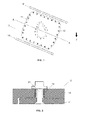
Figure 1 schematically shows thecover 11 of a fuel tank access opening which is joined to thelower skin 13 of the wing by means ofbolted joints 12 according to the prior art andFigure 2 shows a cross section of one boltedjoint 12. - The
cover 11 has a symmetry axis A-A in the direction of the span of the wing substantially parallel to the reinforcingstringers 15, 15' of thelower skin 13 of the wing. - As can be seen in
Figure 2 , there is a hole clearance between abushing 14 joined to thelower skin 13 and thebolt 31, whereas thecover 11 has a countersunk hole with no hole clearances. This means that thecover 11 movies with the bolt 31 (to which it is fixed) with respect to thelower skin 13. - Ideally the
cover 11 should not support loads. For this to happen, thebolts 31 of thejoints 12 must not contact thebushings 14 of thelower skin 13. Otherwise, loads would be transmitted from thelower skin 13 to thecover 11. - Due to the bending moments supported by the wings, the
bolts 31 can enter into contact with thebushings 14 of thelower skin 13, thus cancelling the hole clearance of thejoints 12 on one side. When the hole clearance of ajoint 12 is cancelled on one side, thecover 11 starts to take loads. This is illustrated inFigure 3 : when abolt 31 is floating inside the hole in abushing 14 of thelower skin 13, the loads L transmitted from thelower skin 13 to thecover 11 are insignificant, but as soon as thebolt 31 touches thebushing 14 of thelower skin 13 on one side, the loads L transmitted from thelower skin 13 to thecover 11 increase dramatically. Consequently, thecover 11 has to be reinforced, with a corresponding increase in weight due to the fact that it does end up carrying loads. - It is an object of the present invention to provide a bolted joint between a primary structure of an aircraft lifting surface (such as a skin of an aircraft wing) and a secondary structure (such as a cover of an opening in the skin of the aircraft wing) that avoids the transmission of loads from the primary structure to the secondary structure.
- It is another object of the present invention to provide a bolted joint between a primary structure of an aircraft lifting surface (such as a skin of an aircraft wing) and a secondary structure (such as a cover of an opening in the skin of the aircraft wing) that allows reducing the weight of the secondary structure.
- These and another objects are met by a bolted joint for connecting a cover of an opening in a primary structure of a lifting surface of an aircraft to said primary structure, the cover having a symmetry axis A-A in the direction of the span of said lifting surface comprising:
- two first bolted joints on either side of the symmetry axis A-A on the side of the cover closest to the root of the lifting surface, or on the side of the cover farthest from the root of the lifting surface, arranged without any clearance in the holes of the primary structure and in the holes of the cover;
- two second bolted joints on either of the symmetry axis A-A on the side of the cover opposite to that of the two first bolted joints, arranged without any clearance in the holes of the primary structure and with a clearance in the holes of the cover in the direction of said symmetry axis A-A;
- a plurality of third bolted joints along the border of the cover arranged without any clearance in the holes of the primary structure and with a radial clearance in the holes of the cover.
- In one embodiment the first, second and third bolted joints comprise a bolt with a bushing fixed to it having the same length L than the width W of the cover.
- Advantageously the hole in the cover and the bushing in the second bolted joints are configured, respectively, with frontal facing surfaces having a frontal clearance Cf between them and with lateral facing surfaces having a linear clearance Cx between them in the direction of said symmetry axis A-A.
- Advantageously the hole in the cover and the bushing in the third bolted joints are configured, respectively, with frontal facing surfaces having a frontal clearance Cf between them and with lateral facing surfaces having a radial clearance Cx between them.
- Other desirable features and advantages of the bolted joint according to this invention will become apparent from the subsequent detailed description of the invention and the appended claims, in relation with the enclosed drawings.
-
-
Figure 1 is a plan view of a cover of a fuel tank access opening in a lower skin of the wing of an aircraft according to the prior art. -
Figure 2 is a section view of one of the joints between said cover and said lower skin. -
Figure 3 is a diagram showing the relation between the load L transferred from the lower skin to the cover and the clearance C in the joints shown inFigures 1 and 2 . -
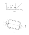
Figure 4 is a plan view of a cover of a fuel tank access opening in a lower skin of the wing of an aircraft according to the present invention. -
Figure 5 is a section view of one embodiment of a joint between said cover and said lower skin according to the present invention. -
Figures 6a and 6b are schematic views of joints with linear and radial clearances. -
Figure 7 is a section view of another embodiment of a joint between said cover and said lower skin according to the present invention. -
Figure 4 illustrates the bolted joint of thecover 11 of a fuel tank access opening in thelower skin 13 of the wing of an aircraft as an example of a bolted joint of a cover of an opening in a primary structure of a lifting surface of an aircraft according to this invention. - The bolted joint comprises:
- Two first fixed
bolted joints 21, 21' on either side of the axis A-A on theside 12 of thecover 11 farthest from the root of the wing (and closest to the incoming flow F). The axis A-A is the symmetry axis of thecover 11 in the wing span direction. The displacements of thelower skin 13 of the wing due to the aerodynamic loads increase along its span. - Two second
bolted joints 23, 23' on theside 10 of thecover 11 closest from the wing root (and farthest from the incoming flow) without any clearance in the holes of thelower skin 13 and with a clearance in the holes of thecover 11 only in the direction of said symmetry axis A-A. - A plurality of third
bolted joints cover 11 without any clearance in the holes of thelower skin 13 and with a radial clearance in the holes of thecover 11. - The fixed bolted
joints 21, 21' ensure that thecover 11 moves with thelower skin 13 of the wing. - These fixed
bolted joints 21, 21' transmit the carried by thelower skin 13 of the wing to thecover 11, but thecover 11 will not carry said loads (and must not be reinforced) unless these loads can be transmitted back to thelower skin 13 through the rest of the bolted joints of thecover 11. In other words, thecover 11 will only carry loads if loads are transmitted from thelower skin 13 to thecover 11 through an entry point and back to thelower skin 13 through an exit point. - In order to avoid this load transfer, the second
bolted joints 23, 23' and the third bolted joins 25, 25', 25", ... have clearances in the holes of thecover 11 avoiding the contact of thebolts 31 with thecover 11. - These clearances must never be cancelled by the displacement of the
lower skin 13 of the wing due to the aerodynamic loads. This means that the clearances must have the dimensions needed for more than compensating the maximum displacement of thelower skin 13 with respect to the fixed boltedjoints 21, 21'. - The fixed
bolted joints 21, 21' provide a reference point because thecover 11 is able to return to a home position each tine due to the second boltedjoints 23, 23', so that the maximum displacements of thecover 11 are limited. Otherwise, thecover 11 could shift in position each time and end at a different home position involving the risk of a situation without a clearance in some of the third boltedjoints -
Figure 5 illustrates an embodiment of a bolted joint with clearances in thecover 11 according to this invention. - The hole in the
lower skin 13 does not have any clearance with respect to thebolt 31. - The
bolt 31 has abushing 33 fixed to it, being the length L of thebushing 33 substantially equal to the width W of thecover 11. - The bushing 33 must be light, conduct electricity and avoid corrosion problems. It can be made of one of the following materials: PEEK, Aluminum, stainless steel or Polyphenylene sulphide (PPS).
- The
hole 30 and thebushing 33 are configured, respectively, with lateral facingsurfaces surfaces - The lateral clearance Cx corresponds to the above mentioned clearances that enable the
cover 11 not to take loads from thelower skin 13. - In the case of a second bolted
joint 23, 23' the lateral clearance Cx is a clearance restricted in a linear direction.Figure 6a schematically shows the clearance between thebolt 31 with thebushing 33 and thecover 11 in these joints allowing one degree of translational freedom. - In the case of a third bolted
joint Figure 6b schematically shows the clearance between thebolt 31 with thebushing 33 and thecover 11 in these joints allowing two degrees of translational freedom. - The frontal clearance Cf allows the implementation of a low friction surface between the frontal facing surfaces 43, 40 of the
bushing 33 and thecover 11 for facilitating relative horizontal displacements between said surfaces. - Several techniques may be used for implementing said low friction surface, for example attaching a Teflon pad (not shown in
Figure 6 ) to one of the facing surfaces 43, 40. - In addition, the
frontal surface 43 of thebushing 33 may be configured with a rounded protruding edge 51 (seeFigure 7 ) that provides a contact point between both frontal facing surfaces regardless of the contact angle between them, helping their relative displacements. - As shown in
Figures 5 and 7 , the bolted joints according to this invention also comprise aseal 49 avoiding fuel leaks but allowing relative displacements between thelower skin 13 and thecover 11. - The bolted joint according to this invention provides a reduction of the weight and the cost of the cover and is particularly applicable to a cover and a primary structure made of a composite material.
- Although the present invention has been described in connection with various embodiments, it will be appreciated from the specification that various combinations of elements, variations or improvements therein may be made, and are within the scope of the invention.
Claims (12)
- Bolted joint for connecting a cover (11) of an opening in a primary structure (13) of a lifting surface of an aircraft to said primary structure (13), the cover (11) having a symmetry axis (A-A) in the direction of the span of said lifting surface, characterized by comprising:- two first bolted joints (21, 21') on either side of the symmetry axis (A-A) on the side of the cover (11) closest to the root of the lifting surface or on the side of the cover (11) farthest from the root of the lifting surface, arranged without any clearance in the holes of the primary structure (13) and in the holes of the cover (11).- two second bolted joints (23, 23') on either side of the symmetry axis (A-A) on the side of the cover (11) opposite to that of the two first bolted joints (21, 21'), arranged without any clearance in the holes of the primary structure (13) and with a clearance in the holes (30) of the cover (11) in the direction of said symmetry axis (A-A);- a plurality of third bolted joints (25, 25', 25", ...) along the border of the cover (11) arranged without any clearance in the holes of the primary structure (13) and with a radial clearance in the holes (30) of the cover (11).
- Bolted joint according to claim 1, wherein:- each first bolted joint (21, 21') comprises a bolt (31) with a bushing (33) fixed to it having the same length (L) than the width (W) of the cover (11);- the hole (30) in the cover (11) and the bushing (33) are configured without any clearance between the .
- Bolted joint according to any of claims 1-2, wherein:- each second bolted joint (23, 23') comprises a bolt (31) with a bushing (33) fixed to it having the same length (L) than the width (W) of the cover (11);- the hole (30) in the cover (11) and the bushing (33) are configured with a linear clearance between the in the direction of said symmetry axis (A-A).
- Bolted joint according to claim 3, wherein said bushing (33) and said hole (30) are configured, respectively, with frontal facing surfaces (43, 40) having a frontal clearance (Cf) between them and with lateral facing surfaces (45, 47; 44, 46) having a linear clearance (Cx) between the in the direction of said symmetry axis (A-A).
- Bolted joint according to any of claims 1-4, wherein:- each third bolted joint (25, 25', 25") comprises a bolt (31) with a bushing (33) fixed to it having the same length (L) than the width (W) of the cover (11)- the hole (30) in the cover (11) and the bushing (33) are configured with a radial clearance between them.
- Bolted joint according to claim 5, wherein said bushing (33) and said hole (30) are configured, respectively, with frontal facing surfaces (43, 40) having a frontal clearance (Cf) between them and with lateral facing surfaces (45, 47; 44, 46) having a radial clearance (Cx) between the .
- Bolted joint according to claim 6, wherein the frontal facing surface (43) of the bushing (33) has a rounded protruding edge (51).
- Bolted joint according to any of claims 1-7, wherein said bushing (33) is made of one of the following materials: PEEK, Aluminum, Stainless Steel, PPS.
- Bolted joint according to any of claims 1-8, wherein said cover (11) and said primary structure (13) are made of a composite material.
- Bolted joint according to any of claims 1-9, wherein said opening in a primary structure (13) is the access opening of a fuel tank in the lower skin of a wing.
- Lifting surface of an aircraft having an opening in a primary structure (13) covered by a cover (11), characterized in that the cover (11) and the primary structure (13) are joined by a bolted joint according to any of claims 1-10.
- Lifting surface according to claim 11, wherein said opening in a primary structure (13) is the access opening of a fuel tank in the lower skin of a wing.
Priority Applications (4)
| Application Number | Priority Date | Filing Date | Title |
|---|---|---|---|
| EP12382152.2A EP2653376B1 (en) | 2012-04-18 | 2012-04-18 | Bolted joint of the cover of an access opening in an aircraft lifting surface |
| ES12382152.2T ES2575028T3 (en) | 2012-04-18 | 2012-04-18 | Screwed connection of the lid of an access opening on a supporting surface of an aircraft |
| US13/845,272 US20130280008A1 (en) | 2012-04-18 | 2013-03-18 | Bolted joint of the cover of an access opening in an aircraft lifting surface |
| CN201310134113.6A CN103373464B (en) | 2012-04-18 | 2013-04-17 | Bolted joint of the cover of an access opening in an aircraft lifting surface |
Applications Claiming Priority (1)
| Application Number | Priority Date | Filing Date | Title |
|---|---|---|---|
| EP12382152.2A EP2653376B1 (en) | 2012-04-18 | 2012-04-18 | Bolted joint of the cover of an access opening in an aircraft lifting surface |
Publications (2)
| Publication Number | Publication Date |
|---|---|
| EP2653376A1 true EP2653376A1 (en) | 2013-10-23 |
| EP2653376B1 EP2653376B1 (en) | 2016-03-23 |
Family
ID=46027885
Family Applications (1)
| Application Number | Title | Priority Date | Filing Date |
|---|---|---|---|
| EP12382152.2A Active EP2653376B1 (en) | 2012-04-18 | 2012-04-18 | Bolted joint of the cover of an access opening in an aircraft lifting surface |
Country Status (4)
| Country | Link |
|---|---|
| US (1) | US20130280008A1 (en) |
| EP (1) | EP2653376B1 (en) |
| CN (1) | CN103373464B (en) |
| ES (1) | ES2575028T3 (en) |
Cited By (5)
| Publication number | Priority date | Publication date | Assignee | Title |
|---|---|---|---|---|
| WO2016055747A1 (en) * | 2014-10-10 | 2016-04-14 | Snecma | Assembly of two parts comprising a removable centring seat for an aircraft turbine engine |
| CN111056020A (en) * | 2019-12-19 | 2020-04-24 | 中国航空工业集团公司西安飞机设计研究所 | Wing oil tank maintenance large opening structure |
| CN111731493A (en) * | 2020-06-18 | 2020-10-02 | 天津爱思达新材料科技有限公司 | Light diffusion structure of aircraft fuel tank hoisting position |
| GB2587391A (en) * | 2019-09-26 | 2021-03-31 | Airbus Operations Ltd | Aircraft assembly |
| GB2591457A (en) * | 2020-01-23 | 2021-08-04 | Bae Systems Plc | Airframe and method of manufacturing an airframe |
Families Citing this family (1)
| Publication number | Priority date | Publication date | Assignee | Title |
|---|---|---|---|---|
| US10179640B2 (en) * | 2016-08-24 | 2019-01-15 | The Boeing Company | Wing and method of manufacturing |
Citations (3)
| Publication number | Priority date | Publication date | Assignee | Title |
|---|---|---|---|---|
| US3357730A (en) * | 1961-10-27 | 1967-12-12 | Joseph T Siler | Methods and means for parts assembly |
| EP0170300A1 (en) * | 1984-07-19 | 1986-02-05 | The Boeing Company | Access panel assembly for aircraft fuel tank |
| FR2828246A1 (en) * | 2001-07-31 | 2003-02-07 | Renault | Stress-free mechanical assembly has positioning system with at least four holes to receive cylindrical elements |
Family Cites Families (12)
| Publication number | Priority date | Publication date | Assignee | Title |
|---|---|---|---|---|
| US4309123A (en) * | 1979-10-26 | 1982-01-05 | Rajac Corporation | Method and apparatus for fastening misaligned structural members |
| US4291816A (en) * | 1980-07-09 | 1981-09-29 | Canadair Limited | Fuel tank access door for aircraft |
| DE3377788D1 (en) * | 1983-11-10 | 1988-09-29 | Boeing Co | Unitary access panel for aircraft fuel tanks |
| JP2001263314A (en) * | 2000-03-17 | 2001-09-26 | Honda Motor Co Ltd | Bolt fastening structure of magnesium alloy member |
| US7338244B2 (en) * | 2004-01-13 | 2008-03-04 | Siemens Power Generation, Inc. | Attachment device for turbine combustor liner |
| JP4729977B2 (en) * | 2005-05-17 | 2011-07-20 | 株式会社ケンウッド | Waterproof structure for fastening parts with screws |
| GB0525896D0 (en) * | 2005-12-20 | 2006-02-01 | Airbus Uk Ltd | A joint for use in aircraft construction |
| EP2210001B1 (en) * | 2007-10-16 | 2017-08-02 | Fatigue Technology, Inc. | Expandable fastener assembly with deformed collar |
| US8777537B2 (en) * | 2007-12-26 | 2014-07-15 | Rolls-Royce North American Technologies, Inc. | Fastener with shear bushing |
| US20090180831A1 (en) * | 2008-01-11 | 2009-07-16 | Kendall Kenneth W | Apparatus and method for tolerance stack-up compensation |
| US8262331B2 (en) * | 2009-05-04 | 2012-09-11 | Polaris Fastening Consulting, Llc | Integrated expanding sleeve hole filling threaded fastener |
| US8267630B2 (en) * | 2009-07-13 | 2012-09-18 | United Technologies Corporation | Threaded flanged bushing for fastening applications |
-
2012
- 2012-04-18 EP EP12382152.2A patent/EP2653376B1/en active Active
- 2012-04-18 ES ES12382152.2T patent/ES2575028T3/en active Active
-
2013
- 2013-03-18 US US13/845,272 patent/US20130280008A1/en not_active Abandoned
- 2013-04-17 CN CN201310134113.6A patent/CN103373464B/en active Active
Patent Citations (3)
| Publication number | Priority date | Publication date | Assignee | Title |
|---|---|---|---|---|
| US3357730A (en) * | 1961-10-27 | 1967-12-12 | Joseph T Siler | Methods and means for parts assembly |
| EP0170300A1 (en) * | 1984-07-19 | 1986-02-05 | The Boeing Company | Access panel assembly for aircraft fuel tank |
| FR2828246A1 (en) * | 2001-07-31 | 2003-02-07 | Renault | Stress-free mechanical assembly has positioning system with at least four holes to receive cylindrical elements |
Cited By (10)
| Publication number | Priority date | Publication date | Assignee | Title |
|---|---|---|---|---|
| WO2016055747A1 (en) * | 2014-10-10 | 2016-04-14 | Snecma | Assembly of two parts comprising a removable centring seat for an aircraft turbine engine |
| FR3027073A1 (en) * | 2014-10-10 | 2016-04-15 | Snecma | TWO-PIECE ASSEMBLY COMPRISING A REMOVABLE CENTERING CUTTER FOR AIRCRAFT TURBOMACHINE |
| CN106795779A (en) * | 2014-10-10 | 2017-05-31 | 赛峰航空器发动机 | For the component of two parts including removable centering pedestal of aircraft turbine |
| CN106795779B (en) * | 2014-10-10 | 2020-01-10 | 赛峰航空器发动机 | Assembly of two parts comprising a removable centring base for an aircraft turbomachine |
| US10533455B2 (en) | 2014-10-10 | 2020-01-14 | Safran Aircraft Engines | Assembly of two parts comprising a removable centring seat for an aircraft turbine engine |
| GB2587391A (en) * | 2019-09-26 | 2021-03-31 | Airbus Operations Ltd | Aircraft assembly |
| CN111056020A (en) * | 2019-12-19 | 2020-04-24 | 中国航空工业集团公司西安飞机设计研究所 | Wing oil tank maintenance large opening structure |
| CN111056020B (en) * | 2019-12-19 | 2023-11-21 | 中国航空工业集团公司西安飞机设计研究所 | Wing oil tank maintains big opening structure |
| GB2591457A (en) * | 2020-01-23 | 2021-08-04 | Bae Systems Plc | Airframe and method of manufacturing an airframe |
| CN111731493A (en) * | 2020-06-18 | 2020-10-02 | 天津爱思达新材料科技有限公司 | Light diffusion structure of aircraft fuel tank hoisting position |
Also Published As
| Publication number | Publication date |
|---|---|
| ES2575028T3 (en) | 2016-06-23 |
| EP2653376B1 (en) | 2016-03-23 |
| US20130280008A1 (en) | 2013-10-24 |
| CN103373464A (en) | 2013-10-30 |
| CN103373464B (en) | 2017-05-17 |
Similar Documents
| Publication | Publication Date | Title |
|---|---|---|
| EP2653376B1 (en) | Bolted joint of the cover of an access opening in an aircraft lifting surface | |
| EP2848519B1 (en) | Upper joints between outboard wing boxes and wing center sections of aircraft wing assemblies | |
| AU2016202359B2 (en) | Pinned fuselage-to-wing connection | |
| CA2831723C (en) | Joint | |
| US20110290941A1 (en) | Attachment system of aircraft components | |
| RU2428353C2 (en) | Airship structural element | |
| EP2845805B1 (en) | Aircraft engine mount | |
| EP3148875B1 (en) | Pressure bulkhead for an aircraft fuselage | |
| US10501163B2 (en) | Pressure bulkhead for an aircraft fuselage, and an aircraft comprising such a pressure bulkhead | |
| US10259557B2 (en) | Pressure bulkhead for an aircraft fuselage, and an aircraft comprising such a pressure bulkhead | |
| US20200156758A1 (en) | Frame assembly for a rear section of an aircraft and rear section of an aircraft comprising said frame assembly | |
| US11027823B2 (en) | Holding device for an aircraft actuator | |
| US8356771B2 (en) | Coupling for joining two frame segments | |
| CN107512399B (en) | Box-shaped beam type engine main mounting joint | |
| JP7473318B2 (en) | Bulkhead Connection Assembly | |
| US20110073711A1 (en) | Joining of structural aircraft elements | |
| CN220281655U (en) | T-shaped lap joint with high bending rigidity | |
| US10364017B2 (en) | Structural component | |
| CN216332703U (en) | Airborne distributed SAR radar repacking structure | |
| US11052991B2 (en) | Fairing for an aircraft | |
| EP3636539A1 (en) | Panel for an aircraft |
Legal Events
| Date | Code | Title | Description |
|---|---|---|---|
| PUAI | Public reference made under article 153(3) epc to a published international application that has entered the european phase |
Free format text: ORIGINAL CODE: 0009012 |
|
| AK | Designated contracting states |
Kind code of ref document: A1 Designated state(s): AL AT BE BG CH CY CZ DE DK EE ES FI FR GB GR HR HU IE IS IT LI LT LU LV MC MK MT NL NO PL PT RO RS SE SI SK SM TR |
|
| AX | Request for extension of the european patent |
Extension state: BA ME |
|
| 17P | Request for examination filed |
Effective date: 20140325 |
|
| RBV | Designated contracting states (corrected) |
Designated state(s): AL AT BE BG CH CY CZ DE DK EE ES FI FR GB GR HR HU IE IS IT LI LT LU LV MC MK MT NL NO PL PT RO RS SE SI SK SM TR |
|
| RIC1 | Information provided on ipc code assigned before grant |
Ipc: B64C 3/34 20060101ALI20140903BHEP Ipc: B64C 1/14 20060101AFI20140903BHEP Ipc: F16B 5/02 20060101ALI20140903BHEP Ipc: B64D 37/14 20060101ALI20140903BHEP |
|
| 17Q | First examination report despatched |
Effective date: 20150119 |
|
| GRAP | Despatch of communication of intention to grant a patent |
Free format text: ORIGINAL CODE: EPIDOSNIGR1 |
|
| INTG | Intention to grant announced |
Effective date: 20151005 |
|
| GRAS | Grant fee paid |
Free format text: ORIGINAL CODE: EPIDOSNIGR3 |
|
| GRAA | (expected) grant |
Free format text: ORIGINAL CODE: 0009210 |
|
| AK | Designated contracting states |
Kind code of ref document: B1 Designated state(s): AL AT BE BG CH CY CZ DE DK EE ES FI FR GB GR HR HU IE IS IT LI LT LU LV MC MK MT NL NO PL PT RO RS SE SI SK SM TR |
|
| REG | Reference to a national code |
Ref country code: GB Ref legal event code: FG4D |
|
| REG | Reference to a national code |
Ref country code: CH Ref legal event code: EP |
|
| REG | Reference to a national code |
Ref country code: AT Ref legal event code: REF Ref document number: 782872 Country of ref document: AT Kind code of ref document: T Effective date: 20160415 |
|
| REG | Reference to a national code |
Ref country code: IE Ref legal event code: FG4D |
|
| REG | Reference to a national code |
Ref country code: FR Ref legal event code: PLFP Year of fee payment: 5 |
|
| REG | Reference to a national code |
Ref country code: DE Ref legal event code: R096 Ref document number: 602012015903 Country of ref document: DE |
|
| REG | Reference to a national code |
Ref country code: ES Ref legal event code: FG2A Ref document number: 2575028 Country of ref document: ES Kind code of ref document: T3 Effective date: 20160623 |
|
| REG | Reference to a national code |
Ref country code: LT Ref legal event code: MG4D |
|
| REG | Reference to a national code |
Ref country code: NL Ref legal event code: MP Effective date: 20160323 |
|
| PG25 | Lapsed in a contracting state [announced via postgrant information from national office to epo] |
Ref country code: FI Free format text: LAPSE BECAUSE OF FAILURE TO SUBMIT A TRANSLATION OF THE DESCRIPTION OR TO PAY THE FEE WITHIN THE PRESCRIBED TIME-LIMIT Effective date: 20160323 Ref country code: HR Free format text: LAPSE BECAUSE OF FAILURE TO SUBMIT A TRANSLATION OF THE DESCRIPTION OR TO PAY THE FEE WITHIN THE PRESCRIBED TIME-LIMIT Effective date: 20160323 Ref country code: GR Free format text: LAPSE BECAUSE OF FAILURE TO SUBMIT A TRANSLATION OF THE DESCRIPTION OR TO PAY THE FEE WITHIN THE PRESCRIBED TIME-LIMIT Effective date: 20160624 Ref country code: NO Free format text: LAPSE BECAUSE OF FAILURE TO SUBMIT A TRANSLATION OF THE DESCRIPTION OR TO PAY THE FEE WITHIN THE PRESCRIBED TIME-LIMIT Effective date: 20160623 |
|
| REG | Reference to a national code |
Ref country code: AT Ref legal event code: MK05 Ref document number: 782872 Country of ref document: AT Kind code of ref document: T Effective date: 20160323 |
|
| PG25 | Lapsed in a contracting state [announced via postgrant information from national office to epo] |
Ref country code: SE Free format text: LAPSE BECAUSE OF FAILURE TO SUBMIT A TRANSLATION OF THE DESCRIPTION OR TO PAY THE FEE WITHIN THE PRESCRIBED TIME-LIMIT Effective date: 20160323 Ref country code: RS Free format text: LAPSE BECAUSE OF FAILURE TO SUBMIT A TRANSLATION OF THE DESCRIPTION OR TO PAY THE FEE WITHIN THE PRESCRIBED TIME-LIMIT Effective date: 20160323 Ref country code: NL Free format text: LAPSE BECAUSE OF FAILURE TO SUBMIT A TRANSLATION OF THE DESCRIPTION OR TO PAY THE FEE WITHIN THE PRESCRIBED TIME-LIMIT Effective date: 20160323 Ref country code: LT Free format text: LAPSE BECAUSE OF FAILURE TO SUBMIT A TRANSLATION OF THE DESCRIPTION OR TO PAY THE FEE WITHIN THE PRESCRIBED TIME-LIMIT Effective date: 20160323 Ref country code: BE Free format text: LAPSE BECAUSE OF NON-PAYMENT OF DUE FEES Effective date: 20160430 Ref country code: LV Free format text: LAPSE BECAUSE OF FAILURE TO SUBMIT A TRANSLATION OF THE DESCRIPTION OR TO PAY THE FEE WITHIN THE PRESCRIBED TIME-LIMIT Effective date: 20160323 |
|
| PG25 | Lapsed in a contracting state [announced via postgrant information from national office to epo] |
Ref country code: IS Free format text: LAPSE BECAUSE OF FAILURE TO SUBMIT A TRANSLATION OF THE DESCRIPTION OR TO PAY THE FEE WITHIN THE PRESCRIBED TIME-LIMIT Effective date: 20160723 Ref country code: EE Free format text: LAPSE BECAUSE OF FAILURE TO SUBMIT A TRANSLATION OF THE DESCRIPTION OR TO PAY THE FEE WITHIN THE PRESCRIBED TIME-LIMIT Effective date: 20160323 Ref country code: PL Free format text: LAPSE BECAUSE OF FAILURE TO SUBMIT A TRANSLATION OF THE DESCRIPTION OR TO PAY THE FEE WITHIN THE PRESCRIBED TIME-LIMIT Effective date: 20160323 |
|
| PG25 | Lapsed in a contracting state [announced via postgrant information from national office to epo] |
Ref country code: PT Free format text: LAPSE BECAUSE OF FAILURE TO SUBMIT A TRANSLATION OF THE DESCRIPTION OR TO PAY THE FEE WITHIN THE PRESCRIBED TIME-LIMIT Effective date: 20160725 Ref country code: CZ Free format text: LAPSE BECAUSE OF FAILURE TO SUBMIT A TRANSLATION OF THE DESCRIPTION OR TO PAY THE FEE WITHIN THE PRESCRIBED TIME-LIMIT Effective date: 20160323 Ref country code: AT Free format text: LAPSE BECAUSE OF FAILURE TO SUBMIT A TRANSLATION OF THE DESCRIPTION OR TO PAY THE FEE WITHIN THE PRESCRIBED TIME-LIMIT Effective date: 20160323 Ref country code: RO Free format text: LAPSE BECAUSE OF FAILURE TO SUBMIT A TRANSLATION OF THE DESCRIPTION OR TO PAY THE FEE WITHIN THE PRESCRIBED TIME-LIMIT Effective date: 20160323 Ref country code: SM Free format text: LAPSE BECAUSE OF FAILURE TO SUBMIT A TRANSLATION OF THE DESCRIPTION OR TO PAY THE FEE WITHIN THE PRESCRIBED TIME-LIMIT Effective date: 20160323 Ref country code: SK Free format text: LAPSE BECAUSE OF FAILURE TO SUBMIT A TRANSLATION OF THE DESCRIPTION OR TO PAY THE FEE WITHIN THE PRESCRIBED TIME-LIMIT Effective date: 20160323 |
|
| REG | Reference to a national code |
Ref country code: CH Ref legal event code: PL |
|
| PG25 | Lapsed in a contracting state [announced via postgrant information from national office to epo] |
Ref country code: BE Free format text: LAPSE BECAUSE OF FAILURE TO SUBMIT A TRANSLATION OF THE DESCRIPTION OR TO PAY THE FEE WITHIN THE PRESCRIBED TIME-LIMIT Effective date: 20160323 Ref country code: IT Free format text: LAPSE BECAUSE OF FAILURE TO SUBMIT A TRANSLATION OF THE DESCRIPTION OR TO PAY THE FEE WITHIN THE PRESCRIBED TIME-LIMIT Effective date: 20160323 |
|
| REG | Reference to a national code |
Ref country code: DE Ref legal event code: R097 Ref document number: 602012015903 Country of ref document: DE |
|
| REG | Reference to a national code |
Ref country code: IE Ref legal event code: MM4A |
|
| PLBE | No opposition filed within time limit |
Free format text: ORIGINAL CODE: 0009261 |
|
| STAA | Information on the status of an ep patent application or granted ep patent |
Free format text: STATUS: NO OPPOSITION FILED WITHIN TIME LIMIT |
|
| PG25 | Lapsed in a contracting state [announced via postgrant information from national office to epo] |
Ref country code: CH Free format text: LAPSE BECAUSE OF NON-PAYMENT OF DUE FEES Effective date: 20160430 Ref country code: DK Free format text: LAPSE BECAUSE OF FAILURE TO SUBMIT A TRANSLATION OF THE DESCRIPTION OR TO PAY THE FEE WITHIN THE PRESCRIBED TIME-LIMIT Effective date: 20160323 Ref country code: LI Free format text: LAPSE BECAUSE OF NON-PAYMENT OF DUE FEES Effective date: 20160430 |
|
| PG25 | Lapsed in a contracting state [announced via postgrant information from national office to epo] |
Ref country code: BG Free format text: LAPSE BECAUSE OF FAILURE TO SUBMIT A TRANSLATION OF THE DESCRIPTION OR TO PAY THE FEE WITHIN THE PRESCRIBED TIME-LIMIT Effective date: 20160623 |
|
| 26N | No opposition filed |
Effective date: 20170102 |
|
| REG | Reference to a national code |
Ref country code: FR Ref legal event code: PLFP Year of fee payment: 6 |
|
| PG25 | Lapsed in a contracting state [announced via postgrant information from national office to epo] |
Ref country code: IE Free format text: LAPSE BECAUSE OF NON-PAYMENT OF DUE FEES Effective date: 20160418 Ref country code: SI Free format text: LAPSE BECAUSE OF FAILURE TO SUBMIT A TRANSLATION OF THE DESCRIPTION OR TO PAY THE FEE WITHIN THE PRESCRIBED TIME-LIMIT Effective date: 20160323 |
|
| REG | Reference to a national code |
Ref country code: FR Ref legal event code: PLFP Year of fee payment: 7 |
|
| PG25 | Lapsed in a contracting state [announced via postgrant information from national office to epo] |
Ref country code: CY Free format text: LAPSE BECAUSE OF FAILURE TO SUBMIT A TRANSLATION OF THE DESCRIPTION OR TO PAY THE FEE WITHIN THE PRESCRIBED TIME-LIMIT Effective date: 20160323 Ref country code: HU Free format text: LAPSE BECAUSE OF FAILURE TO SUBMIT A TRANSLATION OF THE DESCRIPTION OR TO PAY THE FEE WITHIN THE PRESCRIBED TIME-LIMIT; INVALID AB INITIO Effective date: 20120418 |
|
| PG25 | Lapsed in a contracting state [announced via postgrant information from national office to epo] |
Ref country code: LU Free format text: LAPSE BECAUSE OF NON-PAYMENT OF DUE FEES Effective date: 20160418 Ref country code: MK Free format text: LAPSE BECAUSE OF FAILURE TO SUBMIT A TRANSLATION OF THE DESCRIPTION OR TO PAY THE FEE WITHIN THE PRESCRIBED TIME-LIMIT Effective date: 20160323 Ref country code: TR Free format text: LAPSE BECAUSE OF FAILURE TO SUBMIT A TRANSLATION OF THE DESCRIPTION OR TO PAY THE FEE WITHIN THE PRESCRIBED TIME-LIMIT Effective date: 20160323 Ref country code: MC Free format text: LAPSE BECAUSE OF FAILURE TO SUBMIT A TRANSLATION OF THE DESCRIPTION OR TO PAY THE FEE WITHIN THE PRESCRIBED TIME-LIMIT Effective date: 20160323 Ref country code: MT Free format text: LAPSE BECAUSE OF NON-PAYMENT OF DUE FEES Effective date: 20160430 |
|
| PG25 | Lapsed in a contracting state [announced via postgrant information from national office to epo] |
Ref country code: AL Free format text: LAPSE BECAUSE OF FAILURE TO SUBMIT A TRANSLATION OF THE DESCRIPTION OR TO PAY THE FEE WITHIN THE PRESCRIBED TIME-LIMIT Effective date: 20160323 |
|
| PGFP | Annual fee paid to national office [announced via postgrant information from national office to epo] |
Ref country code: FR Payment date: 20230420 Year of fee payment: 12 Ref country code: ES Payment date: 20230627 Year of fee payment: 12 Ref country code: DE Payment date: 20230420 Year of fee payment: 12 |
|
| PGFP | Annual fee paid to national office [announced via postgrant information from national office to epo] |
Ref country code: GB Payment date: 20230419 Year of fee payment: 12 |