EP2653250A1 - Sawing unit for wood - Google Patents
Sawing unit for wood Download PDFInfo
- Publication number
- EP2653250A1 EP2653250A1 EP13164234.0A EP13164234A EP2653250A1 EP 2653250 A1 EP2653250 A1 EP 2653250A1 EP 13164234 A EP13164234 A EP 13164234A EP 2653250 A1 EP2653250 A1 EP 2653250A1
- Authority
- EP
- European Patent Office
- Prior art keywords
- blade
- shaft
- oscillating body
- oscillation
- motor
- Prior art date
- Legal status (The legal status is an assumption and is not a legal conclusion. Google has not performed a legal analysis and makes no representation as to the accuracy of the status listed.)
- Granted
Links
Images
Classifications
-
- B—PERFORMING OPERATIONS; TRANSPORTING
- B23—MACHINE TOOLS; METAL-WORKING NOT OTHERWISE PROVIDED FOR
- B23D—PLANING; SLOTTING; SHEARING; BROACHING; SAWING; FILING; SCRAPING; LIKE OPERATIONS FOR WORKING METAL BY REMOVING MATERIAL, NOT OTHERWISE PROVIDED FOR
- B23D45/00—Sawing machines or sawing devices with circular saw blades or with friction saw discs
- B23D45/06—Sawing machines or sawing devices with circular saw blades or with friction saw discs with a circular saw blade arranged underneath a stationary work-table
- B23D45/065—Sawing machines or sawing devices with circular saw blades or with friction saw discs with a circular saw blade arranged underneath a stationary work-table with the saw blade carried by a pivoted lever
- B23D45/066—Sawing machines or sawing devices with circular saw blades or with friction saw discs with a circular saw blade arranged underneath a stationary work-table with the saw blade carried by a pivoted lever the pivoted lever being mounted on a carriage
-
- B—PERFORMING OPERATIONS; TRANSPORTING
- B23—MACHINE TOOLS; METAL-WORKING NOT OTHERWISE PROVIDED FOR
- B23D—PLANING; SLOTTING; SHEARING; BROACHING; SAWING; FILING; SCRAPING; LIKE OPERATIONS FOR WORKING METAL BY REMOVING MATERIAL, NOT OTHERWISE PROVIDED FOR
- B23D47/00—Sawing machines or sawing devices working with circular saw blades, characterised only by constructional features of particular parts
- B23D47/08—Sawing machines or sawing devices working with circular saw blades, characterised only by constructional features of particular parts of devices for bringing the circular saw blade to the workpiece or removing same therefrom
Definitions
- the invention relates to a sawing unit, in particular for machining wooden workpieces or workpieces made of a material that is similar to wood, and a (circular) saw apparatus comprising the aforesaid sawing unit.
- the sawing unit and the corresponding saw apparatus can be usefully employed in a machine for sectioning panels.
- a sawing unit having a blade the height of which is variable, in particular for enabling the blade to disappear below the horizontal supporting plane of the workpiece during the return stroke along the cutting axis and/or for adjusting the protrusion of the blade above the supporting plane.
- Circular saws for wood are already known that have a circular blade that can be raised and lowered and which is connected to a drive motor by a blade-height varying device, in such a manner as to prevent or limit the movements of great masses, in particular the mass of the drive motor.
- DE 19532726 shows a circular saw with a carriage that is horizontally movable below the workpiece-holding table and a vertically movable blade-holding slide, in which a motor arranged on the carriage drives the blade by a continuous drive belt guided by a group of pulleys comprising a pulley that is coaxial to the drive shaft, a pulley that is coaxial to the blade shaft, a pulley mounted on the lower end of the blade-holding slide and two auxiliary pulleys arranged on the carriage on top of one another; the belt branches coming from the drive shaft are guided by the auxiliary pulleys arranged on the carriage; the belt branch that leaves the upper auxiliary pulley is guided on the pulley that is coaxial to the blade and the belt branch that leaves the lower auxiliary pulley is guided on the pulley mounted at the bottom on the slide.
- EP 1815930 shows a circular saw for wood in which the protrusion of the saw, above the table on which the workpiece is supported, can be varied by a double rocker device, in which a lower rocker is connected to the drive shaft, an upper rocker is connected to the saw shaft and the two rockers are connected together on a movable axis.
- EP 1990114 shows a circular saw carried by a vertically movable carriage on a base; the saw is driven, via a dual belt transmission, by a motor arranged on a rocker hinged on the carriage; the motor is supported by an arm hinged on one side to the rocker and on the other side to the base; simultaneously with the vertical movement of the carriage the motor performs a movement comprising about two linear movements.
- EP 1992438 shows a circular saw with a blade of adjustable height arranged on an adjusting carriage that is movable with respect to the axis of the drive shaft, wherein a drive belt is guided around the drive shaft, around the blade shaft, around a first transmission pulley in a fixed position compared with the axis of the drive shaft and around a second transmission pulley that is movable together with the axis of the blade shaft to compensate for the variation of the distance between the drive shaft and the blade shaft.
- One object of the invention is to make a sawing unit having a blade with a variable height.
- One advantage is to permit a height-varying movement in which the blade moves in relation to the workpiece machining plane.
- One advantage is to enable the height of the blade to be varied, limiting movements of great mass, in particular of the mass of the drive motor, in a vertical direction.
- One advantage is to enable the height of the blade to be varied by varying the height of the motor slightly.
- One advantage is to simplify the control of the height of the blade and to improve the quality and the precision of the workpieces machined by the saw unit.
- One advantage is to provide a constructionally simple and cheap sawing unit.
- One advantage is to rotate the blade by a motor of relatively large size without problems of interference with other elements.
- One advantage is to make a sawing unit available that has a balanced anti-imbalance structure, in particular a structure with a centre of gravity that can be located on the lying plane of the linear guides along which the sawing unit is movable below the machining plane with a cutting stroke and a return stroke.
- One object of the invention is to provide a circular saw apparatus having the aforesaid sawing unit.
- a sawing unit comprises a movable support below a workpiece machining plane and an oscillating body that is carried by the support and in turn carries a rotating blade, a blade-driving motor and a system for transmitting motion from the motor to the blade; the oscillating body can oscillate in such a manner as to vary the height of the blade in relation to the machining plane.
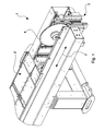
- Figure 1 is a perspective view of a circular saw apparatus of known type.
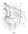
- Figure 1 is a perspective view of an example of a sawing unit according to the invention.
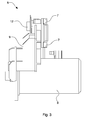
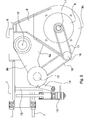
- Figure 3 is a vertical raised side view of the sawing unit in figure 2 .
- Figure 4 is a view from the left of figure 3 .
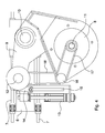
- Figure 5 is a view as in figure 4 with the sawing unit in a different operating configuration.
- a circular saw apparatus of known type has been indicated overall, for machining wooden workpieces or workpieces made of a material equivalent to wood.
- the saw apparatus can be used for cutting (sectioning) workpieces into panel shapes.
- the saw apparatus comprises a supporting table 2 for supporting the workpiece and a sawing unit 3 that is movable below the supporting table.
- the sawing unit is movable in one direction F (both ways) that is substantially parallel to the (horizontal) plane defined by the supporting table 2.
- F both ways
- With the sawing unit 3 at least one circular blade 4 is operationally associated that can traverse the supporting table 2.
- the height of the blade 4 is variable in such a manner as to take the blade below the (horizontal) supporting plane of the workpiece defined by the table 2 in a position of disengagement from the workpiece (to permit the return stroke of the blade after the cutting stroke) and/or to vary the protrusion of the blade above the aforesaid supporting plane.
- the sawing unit 5 can be applied, for example, to the saw apparatus 1 of Figure 1 in replacement of the sawing unit 3 of known type.
- the sawing unit 5 will be movable below the supporting table 2 in the direction F (both ways).
- at least one circular blade 4 will be operationally associated that can traverse the supporting table 2 and the height of which is variable in such a manner as to vary the protrusion of the blade above the (horizontal) supporting plane of the workpiece defined by the table 2 and in such a manner as to take the blade below the table 2 in a disengagement position.
- the sawing unit 5 comprises a support 6 coupled with a frame of the saw apparatus 1.
- the support 6 will be movable on the frame at the command of the driving means.
- the support 6 may be, in particular, coupled with the frame with the possibility of sliding in the machining direction F parallel to the supporting table 2.
- the support 6 may be coupled with the frame of the saw apparatus 1 by (horizontal) linear sliding guides 7.
- the sawing unit 5 comprises a motor 8 carried by an oscillating body 9 that is in turn supported by the support 6 with the possibility of oscillating, in particular rotating around an oscillation axis 10.
- the motor 8 will have a drive shaft 11 with a horizontal rotation axis (parallel to the oscillation axis 10).
- the sawing unit 5 comprises a blade shaft 12 carried by the oscillating body 9.
- the blade shaft 12 (with a horizontal rotation axis and/or rotation axis parallel to the oscillation axis 10) is arranged for supporting a blade, in particular a circular blade, for example the rotating saw blade 4 in figure 1 .
- the coupling means will be associated that are suitable for coupling the circular blade removably with the shaft 12.
- the sawing unit 5 comprises transmission means for transmitting motion from the drive shaft 11 to the blade shaft 12.
- Such transmission means will in particular comprise flexible tensile means.
- the oscillating body 9 is arranged for supporting the motor 8 with the drive shaft 11, the blade shaft 12 and the aforesaid motion transmission means.
- the oscillating body 9 is connected to the support 6 with the possibility of oscillating, with consequent oscillation of the elements carried by the oscillating body 9, such as, in particular, the motor 8, the blade shaft 12 and the motion transmission means.
- the oscillating body 9 is rotatably coupled with the support 6 with the possibility of rotation around the oscillation axis 10 with a horizontal rotation axis.
- the oscillating body 9 will in particular have the possibility of oscillating between two end positions (for example two positions defined by two stops of the drive means of the oscillating body) by performing an oscillating stroke (in particular limited both ways) during which the component in the vertical direction of the oscillation of the blade shaft 12 is greater than the component in a vertical direction of the oscillation that in a corresponding manner (i.e. together with the oscillation of the shaft 12), the motor 8 performs.
- the blade shaft 12 and the motor 8 are, substantially, arranged on the oscillating body 9 in such a manner that, whilst the oscillating body 9 is commanded to perform oscillations along the oscillating stroke thereof, the blade shaft 12 consequently performs oscillations in a prevalently vertical direction, whilst the motor 8 performs oscillations in a prevalently horizontal direction or anyway with a component in a vertical direction that is much less than the vertical component of the blade shaft 12.
- the drive shaft 11, during the oscillating stroke of the oscillating body 9, is always arranged below the oscillation axis 10 and/or the blade shaft 12.
- the blade shaft 12 may have, as in the specific case, a rotation axis arranged in such a manner that, during the oscillating stroke, this axis moves from an upper position ( figure 4 ) to a lower position ( figure 5 ) wherein it is arranged at a height that is, respectively, greater and less than the oscillation axis 10 (as visible in figures 4 and 5 ).
- the oscillating body 9 may have, in particular, a central portion 9a, a side portion 9b and a lower portion 9c.
- the central portion 9a is traversed by the oscillation axis 10 of the body.
- the side portion 9b protrudes laterally from the central portion 9a and is traversed by the rotation axis of the blade shaft 12.
- the lower portion 9c protrudes downwards from the central portion 9a and is traversed by the rotation axis of the drive shaft 11.
- the sawing unit 5 comprises driving means carried by the support 6 for commanding the oscillating body 9 to oscillate.
- this driving means comprises a linear actuator 13 (with a vertical axis) mounted on the support 6 is connected to the oscillating body 9 by a connecting rod 14.
- the linear actuator 13 may be driven electrically, pneumatically, hydraulically, etc.
- the driving means may further comprise a cursor that is integral with a movable element of the actuator 13.
- the cursor is slidably coupled with a linear guide 15 (with a guide axis that is parallel to the axis of the actuator 13).
- the connecting rod 14 will have an end articulated on the (linearly movable) cursor and an opposite end articulated on the oscillating body 9.
- the transmission means may comprise, as in this example, a transmission shaft 16 rotatably supported (with a horizontal rotation axis and/or parallel to the oscillation axis 10) by the oscillating body 9.
- the transmission shaft 16 is arranged, in particular, vertically below the blade shaft 12 at the upper position of the shaft ( figure 4 ).
- the transmission means may comprise, in particular, two endless flexible members in which a first flexible member 17 is wound around the drive shaft 11 and around a first end of the transmission shaft 16, and a second flexible member 18 is wound around a second end (opposite the first) of the transmission shaft 16 and around the blade shaft 12.
- the endless flexible members 17 and 18 may be, for example, two drive belts wound on two pairs of pulleys.
- the height of the blade 4 is varied by driving the actuator 13.
- Lifting the movable element of the actuator 13 will cause the blade 4 to lift up, vice versa for lowering.
- the oscillating body 9 will oscillate in one direction (in the clockwise direction with reference to figures 4 and 5 ) such as to lift the blade shaft 12 and thus the blade 4 rotatably supported by the shaft 12, whilst the lowering of the actuator 13 will cause oscillation in the opposite direction (anticlockwise) and thus lowering of the blade 4.
- the motor 8 and the motion transmission means (the shaft 16, the flexible members 17 and 18 and the corresponding pulleys) will move together with the blade shaft 12, to form a group that is integral with the oscillating body 9.
- the movement of the motor 8 in a vertical direction is minimal. This simplifies the height adjustment of the blade and further favours the stability and precision of the sawing unit.
- the position of the motor 8, located below the oscillation axis 10 enables the motor to perform movements in a mainly horizontal direction.
- the distance of the drive shaft 11 from the oscillation axis is greater than the distance of the blade shaft 12 from the oscillation axis, so that the component in a vertical direction of the motor, is also for this reason, relatively reduced.
- the motion transmission means has a flexible-member dual transmission. It is possible to provide other types of motion transmission, for example a system with a single transmission having a flexible endless member wound directly around the drive shaft and around the blade shaft, in particular without the use of an intermediate driven shaft and of a second endless flexible member, as in the case illustrated above.
Landscapes
- Engineering & Computer Science (AREA)
- Mechanical Engineering (AREA)
- Sawing (AREA)
- Dovetailed Work, And Nailing Machines And Stapling Machines For Wood (AREA)
Abstract
Description
- The invention relates to a sawing unit, in particular for machining wooden workpieces or workpieces made of a material that is similar to wood, and a (circular) saw apparatus comprising the aforesaid sawing unit.
- Specifically, but not exclusively, the sawing unit and the corresponding saw apparatus can be usefully employed in a machine for sectioning panels.
- In particular, reference is made to a sawing unit having a blade the height of which is variable, in particular for enabling the blade to disappear below the horizontal supporting plane of the workpiece during the return stroke along the cutting axis and/or for adjusting the protrusion of the blade above the supporting plane.
- Circular saws for wood are already known that have a circular blade that can be raised and lowered and which is connected to a drive motor by a blade-height varying device, in such a manner as to prevent or limit the movements of great masses, in particular the mass of the drive motor.
-
DE 19532726 shows a circular saw with a carriage that is horizontally movable below the workpiece-holding table and a vertically movable blade-holding slide, in which a motor arranged on the carriage drives the blade by a continuous drive belt guided by a group of pulleys comprising a pulley that is coaxial to the drive shaft, a pulley that is coaxial to the blade shaft, a pulley mounted on the lower end of the blade-holding slide and two auxiliary pulleys arranged on the carriage on top of one another; the belt branches coming from the drive shaft are guided by the auxiliary pulleys arranged on the carriage; the belt branch that leaves the upper auxiliary pulley is guided on the pulley that is coaxial to the blade and the belt branch that leaves the lower auxiliary pulley is guided on the pulley mounted at the bottom on the slide. -
EP 1815930 shows a circular saw for wood in which the protrusion of the saw, above the table on which the workpiece is supported, can be varied by a double rocker device, in which a lower rocker is connected to the drive shaft, an upper rocker is connected to the saw shaft and the two rockers are connected together on a movable axis. -
EP 1990114 shows a circular saw carried by a vertically movable carriage on a base; the saw is driven, via a dual belt transmission, by a motor arranged on a rocker hinged on the carriage; the motor is supported by an arm hinged on one side to the rocker and on the other side to the base; simultaneously with the vertical movement of the carriage the motor performs a movement comprising about two linear movements. -
EP 1992438 shows a circular saw with a blade of adjustable height arranged on an adjusting carriage that is movable with respect to the axis of the drive shaft, wherein a drive belt is guided around the drive shaft, around the blade shaft, around a first transmission pulley in a fixed position compared with the axis of the drive shaft and around a second transmission pulley that is movable together with the axis of the blade shaft to compensate for the variation of the distance between the drive shaft and the blade shaft. - One object of the invention is to make a sawing unit having a blade with a variable height.
- One advantage is to permit a height-varying movement in which the blade moves in relation to the workpiece machining plane.
- One advantage is to enable the height of the blade to be varied, limiting movements of great mass, in particular of the mass of the drive motor, in a vertical direction.
- One advantage is to enable the height of the blade to be varied by varying the height of the motor slightly.
- One advantage is to simplify the control of the height of the blade and to improve the quality and the precision of the workpieces machined by the saw unit.
- One advantage is to provide a constructionally simple and cheap sawing unit.
- One advantage is to rotate the blade by a motor of relatively large size without problems of interference with other elements.
- One advantage is to make a sawing unit available that has a balanced anti-imbalance structure, in particular a structure with a centre of gravity that can be located on the lying plane of the linear guides along which the sawing unit is movable below the machining plane with a cutting stroke and a return stroke.
- One object of the invention is to provide a circular saw apparatus having the aforesaid sawing unit.
- Such objects and advantages and still others are all achieved by the saw unit and apparatus according to one or more of the claims set out below.
- In one example, a sawing unit comprises a movable support below a workpiece machining plane and an oscillating body that is carried by the support and in turn carries a rotating blade, a blade-driving motor and a system for transmitting motion from the motor to the blade; the oscillating body can oscillate in such a manner as to vary the height of the blade in relation to the machining plane.
- The invention can be better understood and implemented with reference to the attached drawings that illustrate one example by way of non-limiting example.
-
Figure 1 is a perspective view of a circular saw apparatus of known type. -
Figure 1 is a perspective view of an example of a sawing unit according to the invention. -
Figure 3 is a vertical raised side view of the sawing unit infigure 2 . -
Figure 4 is a view from the left offigure 3 . -
Figure 5 is a view as infigure 4 with the sawing unit in a different operating configuration. - With reference to
figure 1 , with 1 a circular saw apparatus of known type has been indicated overall, for machining wooden workpieces or workpieces made of a material equivalent to wood. In particular, the saw apparatus can be used for cutting (sectioning) workpieces into panel shapes. - The saw apparatus comprises a supporting table 2 for supporting the workpiece and a
sawing unit 3 that is movable below the supporting table. The sawing unit is movable in one direction F (both ways) that is substantially parallel to the (horizontal) plane defined by the supporting table 2. With thesawing unit 3 at least onecircular blade 4 is operationally associated that can traverse the supporting table 2. The height of theblade 4 is variable in such a manner as to take the blade below the (horizontal) supporting plane of the workpiece defined by the table 2 in a position of disengagement from the workpiece (to permit the return stroke of the blade after the cutting stroke) and/or to vary the protrusion of the blade above the aforesaid supporting plane. - With reference to
figures 2 to 5 , an example of asawing unit 5 made according to the present invention is now disclosed. Thesawing unit 5 can be applied, for example, to the saw apparatus 1 ofFigure 1 in replacement of thesawing unit 3 of known type. Thus also thesawing unit 5 will be movable below the supporting table 2 in the direction F (both ways). Also with thesawing unit 3 at least onecircular blade 4 will be operationally associated that can traverse the supporting table 2 and the height of which is variable in such a manner as to vary the protrusion of the blade above the (horizontal) supporting plane of the workpiece defined by the table 2 and in such a manner as to take the blade below the table 2 in a disengagement position. - The
sawing unit 5 according to the invention comprises asupport 6 coupled with a frame of the saw apparatus 1. Thesupport 6 will be movable on the frame at the command of the driving means. Thesupport 6 may be, in particular, coupled with the frame with the possibility of sliding in the machining direction F parallel to the supporting table 2. Thesupport 6 may be coupled with the frame of the saw apparatus 1 by (horizontal) linearsliding guides 7. - The
sawing unit 5 comprises amotor 8 carried by an oscillatingbody 9 that is in turn supported by thesupport 6 with the possibility of oscillating, in particular rotating around anoscillation axis 10. Themotor 8 will have adrive shaft 11 with a horizontal rotation axis (parallel to the oscillation axis 10). - The
sawing unit 5 comprises ablade shaft 12 carried by the oscillatingbody 9. The blade shaft 12 (with a horizontal rotation axis and/or rotation axis parallel to the oscillation axis 10) is arranged for supporting a blade, in particular a circular blade, for example the rotatingsaw blade 4 infigure 1 . With theblade shaft 12 the coupling means will be associated that are suitable for coupling the circular blade removably with theshaft 12. - The
sawing unit 5 comprises transmission means for transmitting motion from thedrive shaft 11 to theblade shaft 12. Such transmission means will in particular comprise flexible tensile means. - The oscillating
body 9 is arranged for supporting themotor 8 with thedrive shaft 11, theblade shaft 12 and the aforesaid motion transmission means. The oscillatingbody 9 is connected to thesupport 6 with the possibility of oscillating, with consequent oscillation of the elements carried by the oscillatingbody 9, such as, in particular, themotor 8, theblade shaft 12 and the motion transmission means. In the specific case the oscillatingbody 9 is rotatably coupled with thesupport 6 with the possibility of rotation around theoscillation axis 10 with a horizontal rotation axis. - The oscillating
body 9 will in particular have the possibility of oscillating between two end positions (for example two positions defined by two stops of the drive means of the oscillating body) by performing an oscillating stroke (in particular limited both ways) during which the component in the vertical direction of the oscillation of theblade shaft 12 is greater than the component in a vertical direction of the oscillation that in a corresponding manner (i.e. together with the oscillation of the shaft 12), themotor 8 performs. - The
blade shaft 12 and themotor 8 are, substantially, arranged on theoscillating body 9 in such a manner that, whilst theoscillating body 9 is commanded to perform oscillations along the oscillating stroke thereof, theblade shaft 12 consequently performs oscillations in a prevalently vertical direction, whilst themotor 8 performs oscillations in a prevalently horizontal direction or anyway with a component in a vertical direction that is much less than the vertical component of theblade shaft 12. - The
drive shaft 11, during the oscillating stroke of the oscillatingbody 9, is always arranged below theoscillation axis 10 and/or theblade shaft 12. - The
blade shaft 12 may have, as in the specific case, a rotation axis arranged in such a manner that, during the oscillating stroke, this axis moves from an upper position (figure 4 ) to a lower position (figure 5 ) wherein it is arranged at a height that is, respectively, greater and less than the oscillation axis 10 (as visible infigures 4 and5 ). - The oscillating
body 9 may have, in particular, acentral portion 9a, aside portion 9b and alower portion 9c. Thecentral portion 9a is traversed by theoscillation axis 10 of the body. Theside portion 9b protrudes laterally from thecentral portion 9a and is traversed by the rotation axis of theblade shaft 12. Thelower portion 9c protrudes downwards from thecentral portion 9a and is traversed by the rotation axis of thedrive shaft 11. - The
sawing unit 5 comprises driving means carried by thesupport 6 for commanding theoscillating body 9 to oscillate. In the specific case, this driving means comprises a linear actuator 13 (with a vertical axis) mounted on thesupport 6 is connected to the oscillatingbody 9 by a connectingrod 14. Thelinear actuator 13 may be driven electrically, pneumatically, hydraulically, etc. The driving means may further comprise a cursor that is integral with a movable element of theactuator 13. The cursor is slidably coupled with a linear guide 15 (with a guide axis that is parallel to the axis of the actuator 13). The connectingrod 14 will have an end articulated on the (linearly movable) cursor and an opposite end articulated on theoscillating body 9. - The transmission means may comprise, as in this example, a
transmission shaft 16 rotatably supported (with a horizontal rotation axis and/or parallel to the oscillation axis 10) by theoscillating body 9. Thetransmission shaft 16 is arranged, in particular, vertically below theblade shaft 12 at the upper position of the shaft (figure 4 ). - The transmission means may comprise, in particular, two endless flexible members in which a first
flexible member 17 is wound around thedrive shaft 11 and around a first end of thetransmission shaft 16, and a secondflexible member 18 is wound around a second end (opposite the first) of thetransmission shaft 16 and around theblade shaft 12. The endlessflexible members - In use, the height of the
blade 4 is varied by driving theactuator 13. Lifting the movable element of theactuator 13 will cause theblade 4 to lift up, vice versa for lowering. In particular, through the effect of the lifting of theactuator 13, theoscillating body 9 will oscillate in one direction (in the clockwise direction with reference tofigures 4 and5 ) such as to lift theblade shaft 12 and thus theblade 4 rotatably supported by theshaft 12, whilst the lowering of theactuator 13 will cause oscillation in the opposite direction (anticlockwise) and thus lowering of theblade 4. Themotor 8 and the motion transmission means (theshaft 16, theflexible members blade shaft 12, to form a group that is integral with theoscillating body 9. - It should be noted that the movement of the
motor 8 in a vertical direction is minimal. This simplifies the height adjustment of the blade and further favours the stability and precision of the sawing unit. In particular, the position of themotor 8, located below theoscillation axis 10, enables the motor to perform movements in a mainly horizontal direction. It should be further noted that the distance of thedrive shaft 11 from the oscillation axis is greater than the distance of theblade shaft 12 from the oscillation axis, so that the component in a vertical direction of the motor, is also for this reason, relatively reduced. - In the specific case disclosed above, the motion transmission means has a flexible-member dual transmission. It is possible to provide other types of motion transmission, for example a system with a single transmission having a flexible endless member wound directly around the drive shaft and around the blade shaft, in particular without the use of an intermediate driven shaft and of a second endless flexible member, as in the case illustrated above.
Claims (10)
- Saw unit (5) comprising:- a support (6);- an oscillating body (9) connected to said support (6) with the possibility of oscillating;- a motor (8) carried by said oscillating body (9), said motor (8) having a motor shaft (11);- a blade shaft (12) carried by said oscillating body (9), said blade shaft (12) being arranged for supporting a blade (4);- transmission means (16, 17, 18) arranged for transmitting the motion from said motor shaft (11) to said blade shaft (12), said transmission means (16, 17, 18) being carried by said oscillating body (9);
wherein the oscillation of said oscillating body (9) entails the oscillation of said motor (8), blade shaft (12) and transmission means (16, 17, 18). - Saw unit according to claim 1, wherein said oscillating body (9) is constrained to oscillate around an oscillation axis (10) between at least two positions of an oscillation stroke during which the component in a vertical direction of the oscillation of said blade shaft (12) is greater than the component in a vertical direction of the oscillation of said motor (8).
- Saw unit according to claim 2, wherein, during said oscillation stroke, said motor shaft (11) is always arranged below said oscillation axis (10) and/or said blade shaft (12).
- Saw unit according to claim 2 o 3, wherein said blade shaft (12) has a rotation axis that, during said oscillation stroke, moves from an upper position to a lower position wherein it is arranged at a height that is respectively higher and lower than said oscillation axis (10).
- Saw unit according to any preceding claim, wherein said oscillating body (9) is constrained to oscillate around an oscillation axis (10), said oscillating body (9) having a central portion (9a) traversed by said oscillation axis (10), a lateral portion (9b) that protrudes laterally from said central portion (9a) and is traversed by said blade shaft (12), and a lower portion (9c) that protrudes downwards from said central portion (9a) and is traversed by said motor shaft (11).
- Saw unit according to any preceding claim, comprising driving means (13) carried by said support (6) to command the oscillation of said oscillating body (9).
- Saw unit according to claim 6, wherein said driving means comprises a linear actuator (13) mounted on said support (6) and connected to said oscillating body (9) by at least one connecting rod (14).
- Saw unit according to any preceding claim, wherein said oscillating body (9) is constrained to oscillate around an oscillation axis (10), and wherein said motor shaft (11), said blade shaft (12) and said oscillation axis (10) are parallel to one another and in particular horizontal.
- Saw unit according to any preceding claim, wherein said transmission means comprises a transmission shaft (16) that is rotatably supported by said oscillating body (9), a first endless flexible member (17) and a second endless flexible member (18), said first endless flexible member (17) being wound around said motor shaft (11) and around a first end of said transmission shaft (16), said second endless flexible member (18) being wound around a second end, opposite the first end, of said transmission shaft (16) and around said blade shaft (12).
- Saw apparatus comprising a table for supporting a workpiece and a saw unit that is movable below said supporting table, said saw unit having a circular blade that traverses said supporting table and is height-variable, characterised in that said saw unit is made according to any one of claims 1 to 9.
Applications Claiming Priority (1)
| Application Number | Priority Date | Filing Date | Title |
|---|---|---|---|
| IT000100A ITMO20120100A1 (en) | 2012-04-18 | 2012-04-18 | GROUP SAW FOR WOOD |
Publications (2)
| Publication Number | Publication Date |
|---|---|
| EP2653250A1 true EP2653250A1 (en) | 2013-10-23 |
| EP2653250B1 EP2653250B1 (en) | 2019-01-16 |
Family
ID=46321290
Family Applications (1)
| Application Number | Title | Priority Date | Filing Date |
|---|---|---|---|
| EP13164234.0A Active EP2653250B1 (en) | 2012-04-18 | 2013-04-18 | Sawing unit for wood |
Country Status (2)
| Country | Link |
|---|---|
| EP (1) | EP2653250B1 (en) |
| IT (1) | ITMO20120100A1 (en) |
Cited By (1)
| Publication number | Priority date | Publication date | Assignee | Title |
|---|---|---|---|---|
| CN108127170A (en) * | 2017-12-21 | 2018-06-08 | 合肥市春华起重机械有限公司 | A kind of burglary-resisting window steel pipe cutting device |
Citations (7)
| Publication number | Priority date | Publication date | Assignee | Title |
|---|---|---|---|---|
| US1988102A (en) * | 1932-04-02 | 1935-01-15 | William H Woodward | Circular saw machine |
| US2067652A (en) * | 1934-08-04 | 1937-01-12 | Herbert E Tautz | Woodworking machine |
| DE4033785A1 (en) * | 1990-10-24 | 1992-04-30 | Lutz Eugen Masch | Mitring saw unit - has rotary saw blade located on pivot arm beneath rotatable workpiece table |
| DE19532726A1 (en) | 1994-10-18 | 1996-04-25 | Schelling & Co | Saw unit for underfloor circular saws |
| EP1815930A1 (en) | 2006-02-02 | 2007-08-08 | Otto Martin Maschinenbau GmbH & Co. KG | Wood working machine, in particular a circular saw with a cutting tool |
| EP1990114A1 (en) | 2007-05-07 | 2008-11-12 | HOLZMA Plattenaufteiltechnik GmbH | Panel machining device |
| EP1992438A2 (en) | 2007-05-14 | 2008-11-19 | Panhans Maschinenbau Gmbh | Circular sawing machine with adjustable circular saw blade |
Family Cites Families (1)
| Publication number | Priority date | Publication date | Assignee | Title |
|---|---|---|---|---|
| KR100635125B1 (en) * | 2006-07-13 | 2006-10-18 | 최이구 | cutter |
-
2012
- 2012-04-18 IT IT000100A patent/ITMO20120100A1/en unknown
-
2013
- 2013-04-18 EP EP13164234.0A patent/EP2653250B1/en active Active
Patent Citations (7)
| Publication number | Priority date | Publication date | Assignee | Title |
|---|---|---|---|---|
| US1988102A (en) * | 1932-04-02 | 1935-01-15 | William H Woodward | Circular saw machine |
| US2067652A (en) * | 1934-08-04 | 1937-01-12 | Herbert E Tautz | Woodworking machine |
| DE4033785A1 (en) * | 1990-10-24 | 1992-04-30 | Lutz Eugen Masch | Mitring saw unit - has rotary saw blade located on pivot arm beneath rotatable workpiece table |
| DE19532726A1 (en) | 1994-10-18 | 1996-04-25 | Schelling & Co | Saw unit for underfloor circular saws |
| EP1815930A1 (en) | 2006-02-02 | 2007-08-08 | Otto Martin Maschinenbau GmbH & Co. KG | Wood working machine, in particular a circular saw with a cutting tool |
| EP1990114A1 (en) | 2007-05-07 | 2008-11-12 | HOLZMA Plattenaufteiltechnik GmbH | Panel machining device |
| EP1992438A2 (en) | 2007-05-14 | 2008-11-19 | Panhans Maschinenbau Gmbh | Circular sawing machine with adjustable circular saw blade |
Cited By (2)
| Publication number | Priority date | Publication date | Assignee | Title |
|---|---|---|---|---|
| CN108127170A (en) * | 2017-12-21 | 2018-06-08 | 合肥市春华起重机械有限公司 | A kind of burglary-resisting window steel pipe cutting device |
| CN108127170B (en) * | 2017-12-21 | 2019-08-23 | 合肥市春华起重机械有限公司 | An anti-theft window steel pipe cutting device |
Also Published As
| Publication number | Publication date |
|---|---|
| EP2653250B1 (en) | 2019-01-16 |
| ITMO20120100A1 (en) | 2013-10-19 |
Similar Documents
| Publication | Publication Date | Title |
|---|---|---|
| CN107971900B (en) | Multi-station numerical control side polishing machine | |
| EP2653250B1 (en) | Sawing unit for wood | |
| JPH0729275B2 (en) | Sheet material cutting machine | |
| CN108326977B (en) | Feeding device of sheet processing equipment | |
| CN208917576U (en) | A cutting device for silk processing | |
| KR20140000745U (en) | Heavy board cutting device | |
| EP2653252A1 (en) | Sawing unit for wood | |
| KR100453622B1 (en) | Ascending and descending device of circular saw blade for acryl-plate sawing machine | |
| KR102925546B1 (en) | Automatic variable cutting machine | |
| CN220330306U (en) | Laser cutting equipment for organic glass | |
| EP2653251A1 (en) | Sawing unit for wood | |
| CN220144896U (en) | Conveying type numerical control four-side sawing machine | |
| KR101362931B1 (en) | cutter | |
| CN211590761U (en) | Bevel edge cutting machine | |
| CN108943185A (en) | A kind of timber trimming equipment | |
| CN110899839A (en) | Cutting device with adjustable work position | |
| CN217195807U (en) | Full-automatic four sides saw cut equipment | |
| CN107114820B (en) | A kind of cigarette block cutting machine | |
| CN108672825B (en) | A kind of cross sliding type wood-based plate auto-translating intercept device | |
| CN109263381A (en) | A kind of environmental protection vertical 3 D numerical controlled carving rope saw all-in-one machine | |
| EP2101971B1 (en) | Automatic machine for cutting an object along a non-flat section | |
| CN210210607U (en) | An automatic foam cutting machine | |
| CN209305213U (en) | A kind of vertical 3 D digital-controlled carving machine | |
| CN208197953U (en) | Carving machine with multiple working positions | |
| CN224254238U (en) | A clamping mechanism for a metalworking lathe |
Legal Events
| Date | Code | Title | Description |
|---|---|---|---|
| PUAI | Public reference made under article 153(3) epc to a published international application that has entered the european phase |
Free format text: ORIGINAL CODE: 0009012 |
|
| AK | Designated contracting states |
Kind code of ref document: A1 Designated state(s): AL AT BE BG CH CY CZ DE DK EE ES FI FR GB GR HR HU IE IS IT LI LT LU LV MC MK MT NL NO PL PT RO RS SE SI SK SM TR |
|
| AX | Request for extension of the european patent |
Extension state: BA ME |
|
| 17P | Request for examination filed |
Effective date: 20140324 |
|
| RBV | Designated contracting states (corrected) |
Designated state(s): AL AT BE BG CH CY CZ DE DK EE ES FI FR GB GR HR HU IE IS IT LI LT LU LV MC MK MT NL NO PL PT RO RS SE SI SK SM TR |
|
| STAA | Information on the status of an ep patent application or granted ep patent |
Free format text: STATUS: EXAMINATION IS IN PROGRESS |
|
| 17Q | First examination report despatched |
Effective date: 20171024 |
|
| GRAP | Despatch of communication of intention to grant a patent |
Free format text: ORIGINAL CODE: EPIDOSNIGR1 |
|
| STAA | Information on the status of an ep patent application or granted ep patent |
Free format text: STATUS: GRANT OF PATENT IS INTENDED |
|
| INTG | Intention to grant announced |
Effective date: 20180822 |
|
| GRAS | Grant fee paid |
Free format text: ORIGINAL CODE: EPIDOSNIGR3 |
|
| GRAA | (expected) grant |
Free format text: ORIGINAL CODE: 0009210 |
|
| STAA | Information on the status of an ep patent application or granted ep patent |
Free format text: STATUS: THE PATENT HAS BEEN GRANTED |
|
| AK | Designated contracting states |
Kind code of ref document: B1 Designated state(s): AL AT BE BG CH CY CZ DE DK EE ES FI FR GB GR HR HU IE IS IT LI LT LU LV MC MK MT NL NO PL PT RO RS SE SI SK SM TR |
|
| REG | Reference to a national code |
Ref country code: GB Ref legal event code: FG4D |
|
| REG | Reference to a national code |
Ref country code: CH Ref legal event code: EP |
|
| REG | Reference to a national code |
Ref country code: IE Ref legal event code: FG4D |
|
| REG | Reference to a national code |
Ref country code: DE Ref legal event code: R096 Ref document number: 602013049801 Country of ref document: DE |
|
| REG | Reference to a national code |
Ref country code: AT Ref legal event code: REF Ref document number: 1089341 Country of ref document: AT Kind code of ref document: T Effective date: 20190215 |
|
| REG | Reference to a national code |
Ref country code: NL Ref legal event code: MP Effective date: 20190116 |
|
| REG | Reference to a national code |
Ref country code: LT Ref legal event code: MG4D |
|
| PG25 | Lapsed in a contracting state [announced via postgrant information from national office to epo] |
Ref country code: NL Free format text: LAPSE BECAUSE OF FAILURE TO SUBMIT A TRANSLATION OF THE DESCRIPTION OR TO PAY THE FEE WITHIN THE PRESCRIBED TIME-LIMIT Effective date: 20190116 |
|
| PG25 | Lapsed in a contracting state [announced via postgrant information from national office to epo] |
Ref country code: PT Free format text: LAPSE BECAUSE OF FAILURE TO SUBMIT A TRANSLATION OF THE DESCRIPTION OR TO PAY THE FEE WITHIN THE PRESCRIBED TIME-LIMIT Effective date: 20190516 Ref country code: ES Free format text: LAPSE BECAUSE OF FAILURE TO SUBMIT A TRANSLATION OF THE DESCRIPTION OR TO PAY THE FEE WITHIN THE PRESCRIBED TIME-LIMIT Effective date: 20190116 Ref country code: PL Free format text: LAPSE BECAUSE OF FAILURE TO SUBMIT A TRANSLATION OF THE DESCRIPTION OR TO PAY THE FEE WITHIN THE PRESCRIBED TIME-LIMIT Effective date: 20190116 Ref country code: LT Free format text: LAPSE BECAUSE OF FAILURE TO SUBMIT A TRANSLATION OF THE DESCRIPTION OR TO PAY THE FEE WITHIN THE PRESCRIBED TIME-LIMIT Effective date: 20190116 Ref country code: FI Free format text: LAPSE BECAUSE OF FAILURE TO SUBMIT A TRANSLATION OF THE DESCRIPTION OR TO PAY THE FEE WITHIN THE PRESCRIBED TIME-LIMIT Effective date: 20190116 Ref country code: NO Free format text: LAPSE BECAUSE OF FAILURE TO SUBMIT A TRANSLATION OF THE DESCRIPTION OR TO PAY THE FEE WITHIN THE PRESCRIBED TIME-LIMIT Effective date: 20190416 Ref country code: SE Free format text: LAPSE BECAUSE OF FAILURE TO SUBMIT A TRANSLATION OF THE DESCRIPTION OR TO PAY THE FEE WITHIN THE PRESCRIBED TIME-LIMIT Effective date: 20190116 |
|
| PG25 | Lapsed in a contracting state [announced via postgrant information from national office to epo] |
Ref country code: GR Free format text: LAPSE BECAUSE OF FAILURE TO SUBMIT A TRANSLATION OF THE DESCRIPTION OR TO PAY THE FEE WITHIN THE PRESCRIBED TIME-LIMIT Effective date: 20190417 Ref country code: RS Free format text: LAPSE BECAUSE OF FAILURE TO SUBMIT A TRANSLATION OF THE DESCRIPTION OR TO PAY THE FEE WITHIN THE PRESCRIBED TIME-LIMIT Effective date: 20190116 Ref country code: BG Free format text: LAPSE BECAUSE OF FAILURE TO SUBMIT A TRANSLATION OF THE DESCRIPTION OR TO PAY THE FEE WITHIN THE PRESCRIBED TIME-LIMIT Effective date: 20190416 Ref country code: LV Free format text: LAPSE BECAUSE OF FAILURE TO SUBMIT A TRANSLATION OF THE DESCRIPTION OR TO PAY THE FEE WITHIN THE PRESCRIBED TIME-LIMIT Effective date: 20190116 Ref country code: IS Free format text: LAPSE BECAUSE OF FAILURE TO SUBMIT A TRANSLATION OF THE DESCRIPTION OR TO PAY THE FEE WITHIN THE PRESCRIBED TIME-LIMIT Effective date: 20190516 Ref country code: HR Free format text: LAPSE BECAUSE OF FAILURE TO SUBMIT A TRANSLATION OF THE DESCRIPTION OR TO PAY THE FEE WITHIN THE PRESCRIBED TIME-LIMIT Effective date: 20190116 |
|
| REG | Reference to a national code |
Ref country code: DE Ref legal event code: R097 Ref document number: 602013049801 Country of ref document: DE |
|
| PG25 | Lapsed in a contracting state [announced via postgrant information from national office to epo] |
Ref country code: SK Free format text: LAPSE BECAUSE OF FAILURE TO SUBMIT A TRANSLATION OF THE DESCRIPTION OR TO PAY THE FEE WITHIN THE PRESCRIBED TIME-LIMIT Effective date: 20190116 Ref country code: AL Free format text: LAPSE BECAUSE OF FAILURE TO SUBMIT A TRANSLATION OF THE DESCRIPTION OR TO PAY THE FEE WITHIN THE PRESCRIBED TIME-LIMIT Effective date: 20190116 Ref country code: DK Free format text: LAPSE BECAUSE OF FAILURE TO SUBMIT A TRANSLATION OF THE DESCRIPTION OR TO PAY THE FEE WITHIN THE PRESCRIBED TIME-LIMIT Effective date: 20190116 Ref country code: EE Free format text: LAPSE BECAUSE OF FAILURE TO SUBMIT A TRANSLATION OF THE DESCRIPTION OR TO PAY THE FEE WITHIN THE PRESCRIBED TIME-LIMIT Effective date: 20190116 Ref country code: CZ Free format text: LAPSE BECAUSE OF FAILURE TO SUBMIT A TRANSLATION OF THE DESCRIPTION OR TO PAY THE FEE WITHIN THE PRESCRIBED TIME-LIMIT Effective date: 20190116 Ref country code: RO Free format text: LAPSE BECAUSE OF FAILURE TO SUBMIT A TRANSLATION OF THE DESCRIPTION OR TO PAY THE FEE WITHIN THE PRESCRIBED TIME-LIMIT Effective date: 20190116 |
|
| PLBE | No opposition filed within time limit |
Free format text: ORIGINAL CODE: 0009261 |
|
| STAA | Information on the status of an ep patent application or granted ep patent |
Free format text: STATUS: NO OPPOSITION FILED WITHIN TIME LIMIT |
|
| PG25 | Lapsed in a contracting state [announced via postgrant information from national office to epo] |
Ref country code: SM Free format text: LAPSE BECAUSE OF FAILURE TO SUBMIT A TRANSLATION OF THE DESCRIPTION OR TO PAY THE FEE WITHIN THE PRESCRIBED TIME-LIMIT Effective date: 20190116 |
|
| REG | Reference to a national code |
Ref country code: CH Ref legal event code: PL |
|
| REG | Reference to a national code |
Ref country code: BE Ref legal event code: MM Effective date: 20190430 |
|
| 26N | No opposition filed |
Effective date: 20191017 |
|
| GBPC | Gb: european patent ceased through non-payment of renewal fee |
Effective date: 20190418 |
|
| PG25 | Lapsed in a contracting state [announced via postgrant information from national office to epo] |
Ref country code: LU Free format text: LAPSE BECAUSE OF NON-PAYMENT OF DUE FEES Effective date: 20190418 Ref country code: MC Free format text: LAPSE BECAUSE OF FAILURE TO SUBMIT A TRANSLATION OF THE DESCRIPTION OR TO PAY THE FEE WITHIN THE PRESCRIBED TIME-LIMIT Effective date: 20190116 |
|
| PG25 | Lapsed in a contracting state [announced via postgrant information from national office to epo] |
Ref country code: LI Free format text: LAPSE BECAUSE OF NON-PAYMENT OF DUE FEES Effective date: 20190430 Ref country code: CH Free format text: LAPSE BECAUSE OF NON-PAYMENT OF DUE FEES Effective date: 20190430 Ref country code: GB Free format text: LAPSE BECAUSE OF NON-PAYMENT OF DUE FEES Effective date: 20190418 |
|
| PG25 | Lapsed in a contracting state [announced via postgrant information from national office to epo] |
Ref country code: BE Free format text: LAPSE BECAUSE OF NON-PAYMENT OF DUE FEES Effective date: 20190430 Ref country code: SI Free format text: LAPSE BECAUSE OF FAILURE TO SUBMIT A TRANSLATION OF THE DESCRIPTION OR TO PAY THE FEE WITHIN THE PRESCRIBED TIME-LIMIT Effective date: 20190116 Ref country code: FR Free format text: LAPSE BECAUSE OF NON-PAYMENT OF DUE FEES Effective date: 20190430 |
|
| PG25 | Lapsed in a contracting state [announced via postgrant information from national office to epo] |
Ref country code: TR Free format text: LAPSE BECAUSE OF FAILURE TO SUBMIT A TRANSLATION OF THE DESCRIPTION OR TO PAY THE FEE WITHIN THE PRESCRIBED TIME-LIMIT Effective date: 20190116 |
|
| REG | Reference to a national code |
Ref country code: AT Ref legal event code: UEP Ref document number: 1089341 Country of ref document: AT Kind code of ref document: T Effective date: 20190116 |
|
| PG25 | Lapsed in a contracting state [announced via postgrant information from national office to epo] |
Ref country code: IE Free format text: LAPSE BECAUSE OF NON-PAYMENT OF DUE FEES Effective date: 20190418 |
|
| PG25 | Lapsed in a contracting state [announced via postgrant information from national office to epo] |
Ref country code: CY Free format text: LAPSE BECAUSE OF FAILURE TO SUBMIT A TRANSLATION OF THE DESCRIPTION OR TO PAY THE FEE WITHIN THE PRESCRIBED TIME-LIMIT Effective date: 20190116 |
|
| PG25 | Lapsed in a contracting state [announced via postgrant information from national office to epo] |
Ref country code: HU Free format text: LAPSE BECAUSE OF FAILURE TO SUBMIT A TRANSLATION OF THE DESCRIPTION OR TO PAY THE FEE WITHIN THE PRESCRIBED TIME-LIMIT; INVALID AB INITIO Effective date: 20130418 Ref country code: MT Free format text: LAPSE BECAUSE OF FAILURE TO SUBMIT A TRANSLATION OF THE DESCRIPTION OR TO PAY THE FEE WITHIN THE PRESCRIBED TIME-LIMIT Effective date: 20190116 |
|
| PG25 | Lapsed in a contracting state [announced via postgrant information from national office to epo] |
Ref country code: MK Free format text: LAPSE BECAUSE OF FAILURE TO SUBMIT A TRANSLATION OF THE DESCRIPTION OR TO PAY THE FEE WITHIN THE PRESCRIBED TIME-LIMIT Effective date: 20190116 |
|
| P01 | Opt-out of the competence of the unified patent court (upc) registered |
Effective date: 20230518 |
|
| PGFP | Annual fee paid to national office [announced via postgrant information from national office to epo] |
Ref country code: DE Payment date: 20250417 Year of fee payment: 13 |
|
| PGFP | Annual fee paid to national office [announced via postgrant information from national office to epo] |
Ref country code: AT Payment date: 20250416 Year of fee payment: 13 |
|
| PGFP | Annual fee paid to national office [announced via postgrant information from national office to epo] |
Ref country code: IT Payment date: 20260206 Year of fee payment: 14 |