EP2651833B1 - Process, apparatus and membrane bioreactor for wastewater treatment - Google Patents
Process, apparatus and membrane bioreactor for wastewater treatment Download PDFInfo
- Publication number
- EP2651833B1 EP2651833B1 EP11849768.4A EP11849768A EP2651833B1 EP 2651833 B1 EP2651833 B1 EP 2651833B1 EP 11849768 A EP11849768 A EP 11849768A EP 2651833 B1 EP2651833 B1 EP 2651833B1
- Authority
- EP
- European Patent Office
- Prior art keywords
- membrane
- aeration
- zone
- tank
- anaerobic
- Prior art date
- Legal status (The legal status is an assumption and is not a legal conclusion. Google has not performed a legal analysis and makes no representation as to the accuracy of the status listed.)
- Active
Links
- 239000012528 membrane Substances 0.000 title claims description 157
- 238000000034 method Methods 0.000 title claims description 50
- 230000008569 process Effects 0.000 title claims description 46
- 238000004065 wastewater treatment Methods 0.000 title claims description 15
- 238000005273 aeration Methods 0.000 claims description 66
- 239000011148 porous material Substances 0.000 claims description 50
- 239000010802 sludge Substances 0.000 claims description 48
- 239000007788 liquid Substances 0.000 claims description 37
- QAOWNCQODCNURD-UHFFFAOYSA-L Sulfate Chemical compound [O-]S([O-])(=O)=O QAOWNCQODCNURD-UHFFFAOYSA-L 0.000 claims description 29
- QVGXLLKOCUKJST-UHFFFAOYSA-N atomic oxygen Chemical compound [O] QVGXLLKOCUKJST-UHFFFAOYSA-N 0.000 claims description 29
- 229910052760 oxygen Inorganic materials 0.000 claims description 29
- 239000001301 oxygen Substances 0.000 claims description 29
- 230000004907 flux Effects 0.000 claims description 26
- UCKMPCXJQFINFW-UHFFFAOYSA-N Sulphide Chemical compound [S-2] UCKMPCXJQFINFW-UHFFFAOYSA-N 0.000 claims description 19
- 239000002351 wastewater Substances 0.000 claims description 19
- CURLTUGMZLYLDI-UHFFFAOYSA-N Carbon dioxide Chemical compound O=C=O CURLTUGMZLYLDI-UHFFFAOYSA-N 0.000 claims description 18
- OKTJSMMVPCPJKN-UHFFFAOYSA-N Carbon Chemical compound [C] OKTJSMMVPCPJKN-UHFFFAOYSA-N 0.000 claims description 15
- 229910002651 NO3 Inorganic materials 0.000 claims description 15
- NHNBFGGVMKEFGY-UHFFFAOYSA-N Nitrate Chemical compound [O-][N+]([O-])=O NHNBFGGVMKEFGY-UHFFFAOYSA-N 0.000 claims description 15
- 229910052799 carbon Inorganic materials 0.000 claims description 15
- IJGRMHOSHXDMSA-UHFFFAOYSA-N Atomic nitrogen Chemical compound N#N IJGRMHOSHXDMSA-UHFFFAOYSA-N 0.000 claims description 13
- 230000001651 autotrophic effect Effects 0.000 claims description 13
- 239000012466 permeate Substances 0.000 claims description 13
- QGZKDVFQNNGYKY-UHFFFAOYSA-N Ammonia Chemical compound N QGZKDVFQNNGYKY-UHFFFAOYSA-N 0.000 claims description 10
- 241000894006 Bacteria Species 0.000 claims description 9
- 229910002092 carbon dioxide Inorganic materials 0.000 claims description 9
- 239000001569 carbon dioxide Substances 0.000 claims description 9
- NINIDFKCEFEMDL-UHFFFAOYSA-N Sulfur Chemical compound [S] NINIDFKCEFEMDL-UHFFFAOYSA-N 0.000 claims description 8
- 238000005260 corrosion Methods 0.000 claims description 8
- 230000007797 corrosion Effects 0.000 claims description 8
- 230000001590 oxidative effect Effects 0.000 claims description 8
- 239000000463 material Substances 0.000 claims description 7
- 229910052717 sulfur Inorganic materials 0.000 claims description 6
- 239000011593 sulfur Substances 0.000 claims description 6
- 229910021529 ammonia Inorganic materials 0.000 claims description 5
- 229910001873 dinitrogen Inorganic materials 0.000 claims description 5
- 239000005416 organic matter Substances 0.000 claims description 5
- 238000005276 aerator Methods 0.000 claims description 4
- 229910052757 nitrogen Inorganic materials 0.000 claims description 4
- 239000004745 nonwoven fabric Substances 0.000 claims description 4
- FAPWRFPIFSIZLT-UHFFFAOYSA-M Sodium chloride Chemical compound [Na+].[Cl-] FAPWRFPIFSIZLT-UHFFFAOYSA-M 0.000 claims description 3
- 238000001914 filtration Methods 0.000 claims description 3
- 239000007789 gas Substances 0.000 claims description 3
- 239000013535 sea water Substances 0.000 claims description 3
- 239000011780 sodium chloride Substances 0.000 claims description 3
- LSNNMFCWUKXFEE-UHFFFAOYSA-N Sulfurous acid Chemical compound OS(O)=O LSNNMFCWUKXFEE-UHFFFAOYSA-N 0.000 claims description 2
- 239000000919 ceramic Substances 0.000 claims description 2
- 239000002131 composite material Substances 0.000 claims description 2
- 239000011152 fibreglass Substances 0.000 claims description 2
- 239000002184 metal Substances 0.000 claims description 2
- 238000002156 mixing Methods 0.000 claims description 2
- 239000004033 plastic Substances 0.000 claims description 2
- 229920000642 polymer Polymers 0.000 claims description 2
- 238000004064 recycling Methods 0.000 claims description 2
- 229910001220 stainless steel Inorganic materials 0.000 claims description 2
- 239000010935 stainless steel Substances 0.000 claims description 2
- 239000010409 thin film Substances 0.000 claims description 2
- 241001148470 aerobic bacillus Species 0.000 claims 1
- 239000000203 mixture Substances 0.000 claims 1
- 150000004764 thiosulfuric acid derivatives Chemical class 0.000 claims 1
- 238000006243 chemical reaction Methods 0.000 description 14
- 238000010586 diagram Methods 0.000 description 14
- 238000004519 manufacturing process Methods 0.000 description 12
- 238000006722 reduction reaction Methods 0.000 description 11
- 230000014759 maintenance of location Effects 0.000 description 10
- 230000009467 reduction Effects 0.000 description 10
- 239000007787 solid Substances 0.000 description 10
- 238000004062 sedimentation Methods 0.000 description 8
- 239000002028 Biomass Substances 0.000 description 7
- 238000004140 cleaning Methods 0.000 description 7
- 238000007254 oxidation reaction Methods 0.000 description 7
- 230000003647 oxidation Effects 0.000 description 6
- 238000011282 treatment Methods 0.000 description 6
- 238000009285 membrane fouling Methods 0.000 description 5
- 239000000126 substance Substances 0.000 description 5
- 239000000370 acceptor Substances 0.000 description 4
- VNWKTOKETHGBQD-UHFFFAOYSA-N methane Chemical compound C VNWKTOKETHGBQD-UHFFFAOYSA-N 0.000 description 4
- 230000000696 methanogenic effect Effects 0.000 description 4
- 244000005700 microbiome Species 0.000 description 4
- 238000009991 scouring Methods 0.000 description 4
- 238000012216 screening Methods 0.000 description 4
- 238000000926 separation method Methods 0.000 description 4
- 239000010865 sewage Substances 0.000 description 4
- XLYOFNOQVPJJNP-UHFFFAOYSA-N water Substances O XLYOFNOQVPJJNP-UHFFFAOYSA-N 0.000 description 4
- 230000001580 bacterial effect Effects 0.000 description 3
- 238000010276 construction Methods 0.000 description 3
- 238000009826 distribution Methods 0.000 description 3
- 238000005516 engineering process Methods 0.000 description 3
- 238000011221 initial treatment Methods 0.000 description 3
- 150000003464 sulfur compounds Chemical class 0.000 description 3
- 238000004174 sulfur cycle Methods 0.000 description 3
- 239000002253 acid Substances 0.000 description 2
- 238000011001 backwashing Methods 0.000 description 2
- 230000008859 change Effects 0.000 description 2
- 230000000694 effects Effects 0.000 description 2
- 238000011010 flushing procedure Methods 0.000 description 2
- 239000010842 industrial wastewater Substances 0.000 description 2
- 230000007246 mechanism Effects 0.000 description 2
- 238000001471 micro-filtration Methods 0.000 description 2
- 239000000758 substrate Substances 0.000 description 2
- 0 C1CC*CC1 Chemical compound C1CC*CC1 0.000 description 1
- RWSOTUBLDIXVET-UHFFFAOYSA-N Dihydrogen sulfide Chemical compound S RWSOTUBLDIXVET-UHFFFAOYSA-N 0.000 description 1
- 108091006149 Electron carriers Proteins 0.000 description 1
- 238000009825 accumulation Methods 0.000 description 1
- 238000003914 acid mine drainage Methods 0.000 description 1
- 244000062766 autotrophic organism Species 0.000 description 1
- 230000009286 beneficial effect Effects 0.000 description 1
- 238000004177 carbon cycle Methods 0.000 description 1
- 230000015556 catabolic process Effects 0.000 description 1
- 230000002860 competitive effect Effects 0.000 description 1
- 230000007423 decrease Effects 0.000 description 1
- 238000006731 degradation reaction Methods 0.000 description 1
- 230000000593 degrading effect Effects 0.000 description 1
- 238000006477 desulfuration reaction Methods 0.000 description 1
- 230000023556 desulfurization Effects 0.000 description 1
- 239000010840 domestic wastewater Substances 0.000 description 1
- 238000005265 energy consumption Methods 0.000 description 1
- 238000000855 fermentation Methods 0.000 description 1
- 230000004151 fermentation Effects 0.000 description 1
- 239000000706 filtrate Substances 0.000 description 1
- 239000002803 fossil fuel Substances 0.000 description 1
- 244000059217 heterotrophic organism Species 0.000 description 1
- 239000012510 hollow fiber Substances 0.000 description 1
- 229910000037 hydrogen sulfide Inorganic materials 0.000 description 1
- 230000007062 hydrolysis Effects 0.000 description 1
- 238000006460 hydrolysis reaction Methods 0.000 description 1
- 239000004615 ingredient Substances 0.000 description 1
- 238000005259 measurement Methods 0.000 description 1
- 230000000813 microbial effect Effects 0.000 description 1
- 238000004172 nitrogen cycle Methods 0.000 description 1
- QJGQUHMNIGDVPM-UHFFFAOYSA-N nitrogen group Chemical group [N] QJGQUHMNIGDVPM-UHFFFAOYSA-N 0.000 description 1
- 235000015097 nutrients Nutrition 0.000 description 1
- 230000036284 oxygen consumption Effects 0.000 description 1
- 230000000737 periodic effect Effects 0.000 description 1
- 230000035699 permeability Effects 0.000 description 1
- 238000011112 process operation Methods 0.000 description 1
- 230000000717 retained effect Effects 0.000 description 1
- 230000002441 reversible effect Effects 0.000 description 1
- DHCDFWKWKRSZHF-UHFFFAOYSA-N sulfurothioic S-acid Chemical compound OS(O)(=O)=S DHCDFWKWKRSZHF-UHFFFAOYSA-N 0.000 description 1
- 239000000725 suspension Substances 0.000 description 1
- 238000000108 ultra-filtration Methods 0.000 description 1
Images


Classifications
-
- C—CHEMISTRY; METALLURGY
- C02—TREATMENT OF WATER, WASTE WATER, SEWAGE, OR SLUDGE
- C02F—TREATMENT OF WATER, WASTE WATER, SEWAGE, OR SLUDGE
- C02F3/00—Biological treatment of water, waste water, or sewage
- C02F3/02—Aerobic processes
- C02F3/12—Activated sludge processes
- C02F3/1236—Particular type of activated sludge installations
- C02F3/1268—Membrane bioreactor systems
- C02F3/1273—Submerged membrane bioreactors
-
- C—CHEMISTRY; METALLURGY
- C02—TREATMENT OF WATER, WASTE WATER, SEWAGE, OR SLUDGE
- C02F—TREATMENT OF WATER, WASTE WATER, SEWAGE, OR SLUDGE
- C02F3/00—Biological treatment of water, waste water, or sewage
- C02F3/30—Aerobic and anaerobic processes
-
- B—PERFORMING OPERATIONS; TRANSPORTING
- B01—PHYSICAL OR CHEMICAL PROCESSES OR APPARATUS IN GENERAL
- B01D—SEPARATION
- B01D63/00—Apparatus in general for separation processes using semi-permeable membranes
- B01D63/08—Flat membrane modules
- B01D63/082—Flat membrane modules comprising a stack of flat membranes
- B01D63/0821—Membrane plate arrangements for submerged operation
-
- C—CHEMISTRY; METALLURGY
- C02—TREATMENT OF WATER, WASTE WATER, SEWAGE, OR SLUDGE
- C02F—TREATMENT OF WATER, WASTE WATER, SEWAGE, OR SLUDGE
- C02F3/00—Biological treatment of water, waste water, or sewage
- C02F3/30—Aerobic and anaerobic processes
- C02F3/302—Nitrification and denitrification treatment
-
- B—PERFORMING OPERATIONS; TRANSPORTING
- B01—PHYSICAL OR CHEMICAL PROCESSES OR APPARATUS IN GENERAL
- B01D—SEPARATION
- B01D2311/00—Details relating to membrane separation process operations and control
- B01D2311/26—Further operations combined with membrane separation processes
- B01D2311/2688—Biological processes
-
- B—PERFORMING OPERATIONS; TRANSPORTING
- B01—PHYSICAL OR CHEMICAL PROCESSES OR APPARATUS IN GENERAL
- B01D—SEPARATION
- B01D2313/00—Details relating to membrane modules or apparatus
- B01D2313/12—Specific discharge elements
-
- B—PERFORMING OPERATIONS; TRANSPORTING
- B01—PHYSICAL OR CHEMICAL PROCESSES OR APPARATUS IN GENERAL
- B01D—SEPARATION
- B01D2313/00—Details relating to membrane modules or apparatus
- B01D2313/26—Specific gas distributors or gas intakes
-
- B—PERFORMING OPERATIONS; TRANSPORTING
- B01—PHYSICAL OR CHEMICAL PROCESSES OR APPARATUS IN GENERAL
- B01D—SEPARATION
- B01D2315/00—Details relating to the membrane module operation
- B01D2315/06—Submerged-type; Immersion type
-
- C—CHEMISTRY; METALLURGY
- C02—TREATMENT OF WATER, WASTE WATER, SEWAGE, OR SLUDGE
- C02F—TREATMENT OF WATER, WASTE WATER, SEWAGE, OR SLUDGE
- C02F2209/00—Controlling or monitoring parameters in water treatment
- C02F2209/22—O2
-
- C—CHEMISTRY; METALLURGY
- C02—TREATMENT OF WATER, WASTE WATER, SEWAGE, OR SLUDGE
- C02F—TREATMENT OF WATER, WASTE WATER, SEWAGE, OR SLUDGE
- C02F2303/00—Specific treatment goals
- C02F2303/20—Prevention of biofouling
-
- C—CHEMISTRY; METALLURGY
- C02—TREATMENT OF WATER, WASTE WATER, SEWAGE, OR SLUDGE
- C02F—TREATMENT OF WATER, WASTE WATER, SEWAGE, OR SLUDGE
- C02F2303/00—Specific treatment goals
- C02F2303/24—Separation of coarse particles, e.g. by using sieves or screens
-
- C—CHEMISTRY; METALLURGY
- C02—TREATMENT OF WATER, WASTE WATER, SEWAGE, OR SLUDGE
- C02F—TREATMENT OF WATER, WASTE WATER, SEWAGE, OR SLUDGE
- C02F3/00—Biological treatment of water, waste water, or sewage
- C02F3/02—Aerobic processes
- C02F3/12—Activated sludge processes
- C02F3/20—Activated sludge processes using diffusers
- C02F3/201—Perforated, resilient plastic diffusers, e.g. membranes, sheets, foils, tubes, hoses
-
- Y—GENERAL TAGGING OF NEW TECHNOLOGICAL DEVELOPMENTS; GENERAL TAGGING OF CROSS-SECTIONAL TECHNOLOGIES SPANNING OVER SEVERAL SECTIONS OF THE IPC; TECHNICAL SUBJECTS COVERED BY FORMER USPC CROSS-REFERENCE ART COLLECTIONS [XRACs] AND DIGESTS
- Y02—TECHNOLOGIES OR APPLICATIONS FOR MITIGATION OR ADAPTATION AGAINST CLIMATE CHANGE
- Y02W—CLIMATE CHANGE MITIGATION TECHNOLOGIES RELATED TO WASTEWATER TREATMENT OR WASTE MANAGEMENT
- Y02W10/00—Technologies for wastewater treatment
- Y02W10/10—Biological treatment of water, waste water, or sewage
Definitions
- This disclosure relates to treatment of wastewaters containing organic matter and nitrogen by using a new category of membrane bioreactor.
- the disclosure relates to a high flux, non-fouling membrane module.
- the disclosure also relates to a process whereby sulfate reduction is used in an anaerobic zone to reduce excess sludge production.
- a Membrane Bioreactor depicted in FIG. 1 , is a type of biological wastewater treatment process. It operates in the mode of activated sludge, i.e., using a suspended growth of biological floc, also known as sludge, composed of bacteria and protozoa processes to oxidize organic carbon in the wastewater. Nevertheless, instead of using a sedimentation process to separate the sludge from the mixed liquid, the MBR process makes use of microfiltration membranes with typical pore size of 0.1 ⁇ m to 1 ⁇ m to separate the sludge from the mixed liquid. The permeate flux across the membrane is limited to below 1 m 3 per m 2 of membrane per day.
- Solids retention time is the average time the sludge stays in the system, and can be defined by: total amount of sludge sludge wastage rate including solids in the effluent
- Hydraulic retention time (HRT), sometimes called “hydraulic residence time” is the average time the water stays in the system, and can be defined by: total volume influent flow rate
- the MBR process normally operates at a hydraulic retention time (HRT) of over 6 hrs and has a soluble Chemical Oxygen Demand (COD) removal efficiency similar to a conventional activated sludge process.
- WO2008/115444 discloses a wastewater treatment system comprising an aerobic membrane bioreactor; and an anaerobic digester system connected to continuously receive wasted solids from the aerobic membrane bioreactor; the anaerobic digester system also being connected to return effluent from the anaerobic digester system continuously to the aerobic membrane bioreactor.
- the membrane bioreactor comprises a membrane separator having an average pore size of at least about 0.01 microns.
- sludge production minimizing processes have been developed recently, these processes lead to either high costs or the need for more space.
- the best option for sludge minimization is using a process which inherently has low sludge production.
- low sludge production can be achieved by using hydrolysis and methanogenic fermentation or using sulfate as the electron acceptor instead of oxygen or nitrate.
- Oxic-Settling-Anaerobic is a wastewater treatment technique employing an anaerobic zone or tank, and is capable of efficiently reducing sludge production and improving the stability of process operation by adding an anaerobic sludge tank in the sludge return line.
- OSA process depicted in FIG. 2 , two biological reactors and a settling tank are needed, which requires a larger real estate footprint.
- the hydraulic retention time (HRT) for OSA process is usually in excess of 4 hours to reduce the production of excess sludge and remove organic matters.
- MEPT Membrane Enhanced Primary Treatment
- a wastewater treatment process is used for treating organic matter and nitrogen contained in the wastewater in a short hydraulic retention time (HRT), minimizing excess sludge, and maintaining a "macrofiltration" membrane module in a high flux operation condition.
- An aeration zone having the membrane module is provided. Wastewater influent is received and treated with activated sludge in the aeration zone. An oxygen surplus is maintained by controlling a rate of oxygen supplied to the aeration zone.
- the wastewater influent is mixed with the activated sludge in the aeration zone to form a first mixed liquid.
- the first mixed liquid is processed in two portions. A first portion of the first mixed liquid is filtered through a membrane forming a permeate as the effluent. A second portion is transferred from the aeration zone to an anaerobic zone forming a second mixed liquid. An equal volume of the second mixed liquid is recycled back to the aerobic zone.
- the terms "aeration zone" and “tank with a continuous oxygen surplus” refer to a zone having a continuous oxygen surplus maintained, e.g., by controlling the rate of aeration such that the rate of oxygen supplied is equal to the rate of oxygen consumed by the microorganisms in the tank.
- the disclosed technology provides a process for treating wastewater containing organic matter, using a new type of membrane (module) for solids separation.
- the process comprises introducing wastewater influent into an oxygen-surplus aeration zone having activated sludge and one or more membrane modules.
- the influent is mixed with the activated sludge in the aeration zone to form a mixed liquid.
- Treated effluent is taken out of the reactor by means of a vacuum pump filtering through the membrane.
- microfiltration or ultrafiltration membranes with pore sizes of 0.1 ⁇ m to 1 ⁇ m or less are used.
- the membranes used in the presently disclosed technology have pore sizes of 5 ⁇ m to 150 ⁇ m, which may be referred to as a "macrofiltration membrane".
- these large pore size membranes can allow individual bacteria to pass through, they are effective to stop large biological floc from passing through the membrane. Therefore the activated sludge can be retained in the aeration tank.
- TMP trans-membrane pressure
- coarse bubble diffusers are mainly used to flush the membrane modules to avoid membrane fouling
- fine bubble diffusers are mainly used to provide dissolved oxygen.
- honeycomb membrane module to house and fix the membrane in the aeration tank to facilitate proper backwashing and operation of the membrane.
- an anaerobic zone can be added to the process. This is implemented by transferring a portion of the mixed liquid from the aeration zone to an oxygen-free anaerobic zone.
- the process includes recycling the mixed liquid in the anaerobic zone back to the aeration zone.
- the membrane module provided in the aeration zone continues to be used for the separation of solids from the mixed liquid so as to form the treated effluent.
- the process can also make use of sulfur compounds for minimizing sludge production.
- Sulfur compounds including sulfate, sulfite, thiosulfate, sulfide or elemental sulfur can be added to the system.
- Possible sulfur sources can be sulfate from seawater, saline sewage through seawater toilet flushing, or industrial wastewater such as acid mine drainage or effluent from desulfurization units of fossil fuel power stations.
- the sulfur compounds will be oxidized to sulfate.
- Part of the sulfate will enter the anaerobic zone and act as the electron acceptor for oxidation of the organic carbon, forming carbon dioxide and sulfide.
- the sulfide will then be recycled back to the aeration tank for conversion to sulfate.
- Part of the sulfate will leave the system with the permeate through the membrane.
- the dissolved oxygen in aeration tank should be kept at a low level of about 2 mg/L.
- the process affords a smaller footprint, higher nutrient removal efficiency, and lower membrane fouling frequency than previous wastewater treatment technologies. This is very suitable for land shortage areas such as Hong Kong and Singapore.
- the membrane module used in this process is produced by Hong Kong University of Science and Technology (HKUST).
- the membranes were housed on a HKUST designed honeycomb module, in which the membrane is held between two thin corrosion-resistant honeycomb plates.
- the corrosion-resistant honeycomb plates support the membrane and keep the membrane in a flat shape, which enables a high efficiency of the membrane module and increases the efficiency of backwash.
- the plates and membrane are installed and fixed on the membrane frame by fasteners such as screws, nuts, and gaskets to enable a close fit for the membrane.
- This equipment forms an integrated HKUST membrane module which is installed into the aeration zone.
- membranes having pore sizes between 0.5 ⁇ m and 220 ⁇ m have been tested for determination of the critical flux as well as observing the biomass accumulation on the membrane surface under a microscope.
- Critical flux is an important parameter to indicate the maximum permeability and workload of a membrane in a MBR system.
- the membrane has to be operated below critical flux (i.e. in the sub-critical flux) to avoid membrane fouling.
- a higher critical flux means a smaller membrane is needed.
- the trans-membrane pressure (TMP) will increase significantly if the operational flux is higher than critical flux.
- the steady state TMP of the membrane operated under different flux is measured to determine the critical flux.
- FIG. 3 is a graph showing the operational trans-membrane pressure (TMP) data in a sub-critical and critical flux of membranes.
- FIG. 3 shows the result of the critical flux measurements with nominal pore sizes of 0.5 ⁇ m, 5 ⁇ m, 55 ⁇ m and 100 ⁇ m.
- critical flux will increase when the pore size increases, with pore size higher than 5 ⁇ m being acceptable, and with pore size higher than 55 ⁇ m optimal; with critical flux up to around 16 m 3 /m 2 d.
- nominal pore sizes because the size of individual pores varies significantly.
- the nominal pore sizes are rough averages of the pore size as produced by the manufacturer.
- FIGs. 4a - 4f are diagrams showing the biomass accumulated on the surface of the membranes with pore sizes from 0.5 ⁇ m to 220 ⁇ m, viewed under a Confocal Laser Scanning Microscope.
- FIGs. 4a - 4f show the biomass accumulated the membrane observed under the microscope.
- FIG. 4a depicts a sample with a 0.5 ⁇ m pore size
- FIG. 4b depicts a sample with a 5 ⁇ m pore size
- FIG. 4c depicts a sample with a 55 ⁇ m pore size
- FIG. 4d depicts a sample with a 100 ⁇ m pore size
- FIG. 4e depicts a sample with a 150 ⁇ m pore size
- the nominal pore size can be in the range of 5 ⁇ m to 150 ⁇ m or 10 ⁇ m to 100 ⁇ m.
- a single membrane can have pores of different sizes which include pores within the stated range, or can have pores within a narrow range of pore sizes in the previously-mentioned ranges.
- FIG. 5 is a schematic diagram illustrating an improved wastewater treatment system. Depicted are influent supply conduit 501, aeration zone or tank (MEPT tank) 502, membrane module 503 with membrane module outlet pipe 507, aeration to anaerobic connection pipe 509, and Oxic-Settling-Anaerobic (OSA) tank 515. OSA tank 515 establishes an anaerobic zone.
- MEPT tank aeration zone or tank
- OSA Oxic-Settling-Anaerobic
- the configuration employs a complete mixing system for treating organic matter and nitrogen-containing wastewater. Wastewater, before entering the system, should first pass through grit removal and screening of 3 mm, but there is no need for suspended solids removal. The wastewater is then fed through a conduit 501 into MEPT tank 502 with a continuous oxygen surplus.
- the oxygen surplus in the aeration zone is such that the rate of oxygen supply is equal to the rate of oxygen consumption by the microorganisms in the tank. This results in dissolved oxygen concentration at about 2 mg/L throughout the tank.
- Aerator devices or a combination of aerator devices and mechanical mixers typically provide oxygen and keep the mixed liquid solids in suspension.
- oxygen supplemented by the aerators or mixers in the aeration tank heterotrophic organisms oxidize organic carbon to carbon dioxide and autotrophic organisms oxidize ammonia to nitrate, as well as the hydrogen sulfide, contained in the mixed liquid which recycled from OSA tank 515, to sulfate.
- the hydraulic retention time in MEPT tank 502 is typically, but not limited to, 1.5 to 2 hours.
- the mixed liquid suspended solids in MEPT tank 502 is about, but not limited to, 3000 mg/L.
- FIG. 6 is a schematic diagram showing a side elevation of one embodiment of a membrane module 503. Depicted are module 503, with outlet 507 and corrosion-resistant honeycomb plates 605 (one shown). Honeycomb plates 605 have honeycombed openings 606 with hole size of 10 mm. The hole size for openings 606 is selected according to the requirements of structural integrity of the honeycomb plate 605 and for supporting the membrane (717, Fig. 7 ) within the module 503.
- One or more membrane modules 503 are installed in MEPT tank 502 where permeate passes through the membrane filters within the modules 503 as effluent while the biological solids are separated by membrane filters and left behind in the MEPT tank 502. Membrane modules 503 need a significant amount of air bubbles not only for supplying oxygen to the microorganisms but also for membrane scouring in order to avoid membrane fouling.
- OSA tank 515 Part of the mixed liquid from MEPT tank 502 then flows to OSA tank 515 through a connection pipe 509.
- OSA tank 515 nitrate and sulfate contained in the mixed liquid from MEPT tank 502 acts as electron acceptors and reduce to nitrogen gas and sulfide by oxidizing organic carbon to carbon dioxide. Part of the nitrate may also act as electron acceptor to oxidize sulfide through autotrophic denitrification.
- the same amount of mixed liquid in OSA tank 515 is then recycled back to MEPT tank 502.
- the hydraulic retention time in OSA tank 515 is typically, but not limited to, 1.5 to 2 hours.
- the mixed liquid suspended solids concentration in OSA tank 515 is about, but not limited to, 3000 mg/L.
- MEPT Membrane Enhanced Primary Treatment
- Membrane Bioreactor (MBR) systems combine biological treatment, involving bacteria (referred to as activated sludge), with membrane separation to treat wastewater.
- Wastewater after passing through grit removal, screening and primary sedimentation, enters an aeration tank filled with activated sludge and fitted with air diffusers for providing oxygen and scouring of the membranes.
- Treated effluent is separated from the sludge by passing through the membrane in the form of permeate.
- MBR typically employ flat sheet or hollow fiber membrane modules submerged in the aeration tank.
- MEPT tank 502 of the wastewater treatment system resembles a MBR without primary sedimentation.
- the membrane used in the MEPT has a nominal pore size of 55 ⁇ m, called as macrofiltration membranes.
- Wastewater, after passing through screening enters the aeration tank through feeding pumps and pipes.
- the effluent is taken out of the reactor by applying a vacuum to the membrane modules to withdraw the permeate through the membranes.
- Course gas bubbles are supplied such that, in use, the coarse bubbles move past the membrane surface are entrained or mixed with a liquid flow and scoured against the membrane surface.
- the course gas bubbles function to dislodge fouling materials from the membrane surface.
- a further source of aeration can be provided within the tank to assist microorganism activity.
- This kind of source is provided by fine bubbles.
- the combined use of aeration for both degrading of organic substances and membrane cleaning, together with the specific macrofiltration membranes, has been shown to enable constant filtrate flow with significant increase in TMP under a very high flux up to 16 m 3 /m 2 d.
- the membrane module is therefore used to establish a flux across the membrane of between 2 and 16 m 3 /m 2 d.
- the MEPT process can be used to provide an effective treatment of domestic or industrial wastewater and to provide effluent resembling secondary treatment plus nitrification.
- This type of submerged membrane process uses membrane modules immersed in an aeration tank. The submerged membrane allows the MEPT process to combine primary treatment, biological treatment and physical separation of sludge in one stage, so that the membrane bioreactor is compact, efficient, economical, and versatile.
- Membrane modules 503 used in this system are produced in HKUST.
- the type of the membrane module is flat sheet with the length-to-width-to-thickness 7:4.3:0.25.
- Corrosion resistant honeycomb plates 605 are fixed onto the membrane module 503 surfaces symmetrically with holes 606 of 10 mm diameter and spacing of 20 mm between centers.
- Outlet 507 for effluent from membrane module 503 is installed on the top of membrane module 503.
- the membrane in the membrane module comprises a material selected from the group consisting of non-woven fabric, plastic, polymer, stainless steel, metal, ceramic, fiber glass or thin film composites.
- FIG. 7 is a diagram illustrating construction of a membrane module 503. Depicted are two membranes 717, each held by two thin corrosion-resistant honeycomb plates 605a, 605b, and fasteners, 731, 732, such as nut and bolt fasteners used for tightening plates 605a, 605b against membrane 717, which is held between two plates 605a and 605b.
- the membrane 717 used is a non-woven fabric flat sheet membrane with nominal pore size ranged from 5 ⁇ m to 150 ⁇ m, with optimum pore size of 55 ⁇ m. All the pore size in this range could be used in this MEPT process.
- the thin corrosion-resistant honeycomb plates 605a, 605b are used to hold membrane 717 so that the membrane shape does not change during operation, and thereby maintains membrane module 503 at a high level of stability."
- permeate flux is more than 10 times larger than traditional membrane bioreactor and backwash flux is even larger than permeate flux. Therefore, membrane 717 must be held in a fixed position tightly by the honeycomb plates 605a, 605b in membrane module 503 in order to avoid changes in shape of membrane 717.
- the thin corrosion-resistant honeycomb plates 605a, 605b used in this system are 1 mm thick which could provide the efficiency of air bubble flushing and control bio-cake growth on the membrane surface.
- the bolts and nuts 731, 732 are installed through the whole membrane module 503 from the front side to the reverse side (or vice-versa). The distance between each bolt is 50 mm which results in membrane 717 being closely fitted within membrane module 503.
- the membrane bioreactor system utilizes an effective and efficient membrane cleaning method.
- Commonly used physical cleaning methods include backwash using effluent and scouring using coarse bubbles in the mixed liquid. In the example shown below, chemical or off-tank cleaning is not needed.
- the backwash using 1% effluent is conducted twice a day, and trans-membrane pressure (TMP) is typically below 0.09 bars after a 1 min. backwash.
- FIG. 8 is a diagram showing a plan view schematic of aeration zone (MEPT tank 502) and illustrates the distribution of aeration diffusers and inflow of influent and recirculation, and illustrates the distribution of aeration diffusers and inflow of influent and recirculation.
- MEPT tank 502 membrane module 503
- aeration holes 808 coarse bubble diffusers
- air diffusers 809 fine bubble diffusers
- holes 813 for influent holes 815 for recycled mixed liquid
- valves 821-825 valves 821-825.
- Aeration holes 808 having a diameter 5 mm for producing coarse bubbles are designed on the bottom of MEPT tank 502 and positioned on both sides of membrane module 503 where scouring membrane module 503 can be quite effectively performed.
- Air diffusers 809 are installed evenly in MEPT tank 502 to provide dissolved oxygen symmetrically in the tank. Influent and recycled mixed liquid from OSA tank 515 flow into MEPT tank 502 from the bottom of the tank in order to guarantee a desired hydraulic retention time (HRT). Holes 813 having a diameter 8 mm are used for influent while holes 815 having a diameter 10 mm are used for recycled mixed liquid. Valves 821-825 installed externally to MEPT tank 502 are controlled by a programmable logic controller (PLC) panel.
- PLC programmable logic controller
- the anaerobic tank (OSA tank) 115 of the wastewater treatment system is a sludge minimizing reactor.
- the heterotrophic oxidation reaction using oxygen or nitrate has a sludge yield coefficient 0.4 g VSS/g COD, which is much higher than the yield coefficient 0.1 g VSS/g COD for anaerobic methanogenic reactions
- diversion of the mixed liquid or sludge from the aeration tank to the anaerobic tank to facilitate anaerobic methanogenic reactions can reduce the overall sludge production.
- the reaction rate of methanogenic reaction is much slower than heterotrophic oxidation, such reaction requires a very long HRT and SRT to remove enable sludge minimization efficiently.
- the OSA process can be added to the MBR process without applying secondary sedimentation.
- Hong Kong sewage contains 500 mgSO 4 2- /L sulfate or 167 mgS/L and 400 mg/L COD, indicating a sufficient sulfate reduction potential.
- As sulfate reduction reaction also has a low sludge yield 0.2 g VSS/g reduced sulfate, it provides an opportunity for sludge minimization using the sulfur cycle.
- As sulfate-reducing bacteria (SRB) have a higher specific growth rate and lower Monod's saturation coefficient than that of methane producing bacteria, they can out-compete methane producing bacteria for degradation of organic substrates, making them suitable for OSA applications.
- SRB sulfate-reducing bacteria
- autotrophic denitrification by sulfide also have a very low sludge yield, the sludge minimization rate with sulfate will not be affected by the nitrate level.
- Reduction of sulfate to sulfide is a change from a strong acid to a weak acid, which would result in the increase in pH.
- sulfide generated from sulfate reduction tends to dissolve in water as pH increases, thereby generating adequate amounts of dissolved sulfide, enable it to be re-circulated to the aeration tank where it would be oxidized by oxygen to sulfate through autotrophic sulfide oxidation.
- this process also has a low sludge yield factor, the sludge production rate of the system would be minimized by this sulfate-sulfide-sulfate cycle.
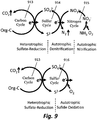
- FIG. 9 is a diagram showing a mechanism of reactions in the aerobic zone (MEPT tank 502) and anaerobic zone (OSA tank 515) involving sulfur. Depicted are representations of a carbon cycle, described as “heterotrophic sulfur reduction” 913, a sulfur cycle described as “autotrophic denitrification” 914, a nitrogen cycle described as “autotrophic nitrification” 915, and another sulfur cycle described as “autotrophic sulfide oxidation” 916. The process results in reactions involving the three elements, carbon, nitrogen and sulfur.
- organic carbon provides electrons to achieve sulfate reduction and is oxidized to carbon dioxide, while sulfate is reduced to sulfide by sulfate reducing bacteria through heterotrophic sulfate reduction 913.
- Nitrate is reduced to nitrogen gas through two competitive reactions, namely autotrophic denitrification 914 oxidizing sulfide to sulfate, or heterotrophic denitrification oxidizing organic carbon to carbon dioxide.
- the mixed liquid recycled to MEPT tank 502 contains dissolved sulfide which will be oxidize to sulfate again by oxygen through autotrophic sulfide oxidation 916 in MEPT tank 502. Part of the organic carbon will also be oxidized by oxygen to carbon dioxide in MEPT tank 502.
- This process significantly reduces excess sludge production because the three major microbial populations in the process -- sulfate reduction bacteria, autotrophic denitrifiers and autotrophic nitrifiers -- all have low growth yields. Growth yields are a function of the bacterial growth rate. The lower growth yield is, the less bacterial mass will produce per unit substrate (e.g. carbon) consumed. Low growth yield is therefore beneficial for the biological sewage treatment process in minimizing sludge production.
- the membrane used is a non-woven fabric membrane with nominal pore size of 55 ⁇ m.
- the size of membrane modules is 0.7 m ⁇ 0.43 m ⁇ 0.025 m with a porosity of 0.42.
- the size of the aeration tank is 0.38 m ⁇ 0.54 m ⁇ 0.97 m and the size of anaerobic tank is 0.4 m ⁇ 0.4 m ⁇ 1.25 m.
- the total volume of the system is 400 L, with each of the reactor roughly equals to 200 L.
- the total HRT is 3.5 hrs while SRT is 36 days.
- the influent entered the aeration tank. Part of the mixed liquid of the aeration tank then entered the anaerobic tank with a recirculation rate equal to the influent inflow rate.
- the air-to-water ratio in aeration tank was around 20-25 (m 3 /m 3 ) while mixed liquid in the anaerobic tank was mixed with a mechanical mixer operating at 40-60 rpm/min.
- the average MLSS in both the aeration tank and anaerobic tank are 3000 - 3500 mg/L.
- the permeate flux of this example was maintained at 10.8 to 11 m 3 /m 2 day.
- Membrane backwash was conducted every 12 hours.
Landscapes
- Life Sciences & Earth Sciences (AREA)
- Chemical & Material Sciences (AREA)
- Engineering & Computer Science (AREA)
- Biodiversity & Conservation Biology (AREA)
- Microbiology (AREA)
- Hydrology & Water Resources (AREA)
- Environmental & Geological Engineering (AREA)
- Water Supply & Treatment (AREA)
- Organic Chemistry (AREA)
- Chemical Kinetics & Catalysis (AREA)
- Separation Using Semi-Permeable Membranes (AREA)
- Filtering Materials (AREA)
- Treatment Of Biological Wastes In General (AREA)
- Activated Sludge Processes (AREA)
- Purification Treatments By Anaerobic Or Anaerobic And Aerobic Bacteria Or Animals (AREA)
Description
- This disclosure relates to treatment of wastewaters containing organic matter and nitrogen by using a new category of membrane bioreactor. In particular, the disclosure relates to a high flux, non-fouling membrane module. The disclosure also relates to a process whereby sulfate reduction is used in an anaerobic zone to reduce excess sludge production.
- A Membrane Bioreactor (MBR), depicted in
FIG. 1 , is a type of biological wastewater treatment process. It operates in the mode of activated sludge, i.e., using a suspended growth of biological floc, also known as sludge, composed of bacteria and protozoa processes to oxidize organic carbon in the wastewater. Nevertheless, instead of using a sedimentation process to separate the sludge from the mixed liquid, the MBR process makes use of microfiltration membranes with typical pore size of 0.1 µm to 1 µm to separate the sludge from the mixed liquid. The permeate flux across the membrane is limited to below 1 m3 per m2 of membrane per day. - To ensure proper functioning of the membrane, special operations have to be arranged to prevent biofouling of the membrane. These include keeping the air-to-water ratio above 25 to provide sufficient self-cleaning of the membranes; frequent backwashing of the membrane once every 30 minutes; and periodic chemical or off-tank cleaning of the membrane every one or two months. All these special operations would result in the increase in energy consumption and operation cost, as well as reduction of effective operational duration. Moreover, to protect the membrane, the influent wastewater has to pass through primary sedimentation and fine-screening of 1 mm before the entering the aeration tank.
- Solids retention time (SRT) is the average time the sludge stays in the system, and can be defined by:

- Hydraulic retention time (HRT), sometimes called "hydraulic residence time", is the average time the water stays in the system, and can be defined by:

- The MBR process normally operates at a hydraulic retention time (HRT) of over 6 hrs and has a soluble Chemical Oxygen Demand (COD) removal efficiency similar to a conventional activated sludge process.
WO2008/115444 discloses a wastewater treatment system comprising an aerobic membrane bioreactor; and an anaerobic digester system connected to continuously receive wasted solids from the aerobic membrane bioreactor; the anaerobic digester system also being connected to return effluent from the anaerobic digester system continuously to the aerobic membrane bioreactor. The membrane bioreactor comprises a membrane separator having an average pore size of at least about 0.01 microns. - Although a number of sludge production minimizing processes have been developed recently, these processes lead to either high costs or the need for more space. The best option for sludge minimization is using a process which inherently has low sludge production. For COD conversion, low sludge production can be achieved by using hydrolysis and methanogenic fermentation or using sulfate as the electron acceptor instead of oxygen or nitrate.
- Oxic-Settling-Anaerobic (OSA) is a wastewater treatment technique employing an anaerobic zone or tank, and is capable of efficiently reducing sludge production and improving the stability of process operation by adding an anaerobic sludge tank in the sludge return line. In an OSA process, depicted in
FIG. 2 , two biological reactors and a settling tank are needed, which requires a larger real estate footprint. The hydraulic retention time (HRT) for OSA process is usually in excess of 4 hours to reduce the production of excess sludge and remove organic matters. - The Membrane Enhanced Primary Treatment (MEPT) is a wastewater treatment process that resembles a membrane bioreactor (MBR) without primary sedimentation, hence its performance effectively combines a primary sedimentation and MBR process.
- A wastewater treatment process is used for treating organic matter and nitrogen contained in the wastewater in a short hydraulic retention time (HRT), minimizing excess sludge, and maintaining a "macrofiltration" membrane module in a high flux operation condition. An aeration zone having the membrane module is provided. Wastewater influent is received and treated with activated sludge in the aeration zone. An oxygen surplus is maintained by controlling a rate of oxygen supplied to the aeration zone. The wastewater influent is mixed with the activated sludge in the aeration zone to form a first mixed liquid. The first mixed liquid is processed in two portions. A first portion of the first mixed liquid is filtered through a membrane forming a permeate as the effluent. A second portion is transferred from the aeration zone to an anaerobic zone forming a second mixed liquid. An equal volume of the second mixed liquid is recycled back to the aerobic zone.
-
-
FIG. 1 is a schematic diagram showing a typical membrane bioreactor. -
FIG. 2 is a schematic diagram showing a typical activated sludge-OSA process. -
FIG. 3 is a graph showing the operational trans-membrane pressure (TMP) data in a sub-critical / critical flux of membranes with pore sizes of 0.5 µm, 5 µm, 55 µm and 100 µm. -
FIGs. 4a - 4f are diagrams showing the biomass accumulated on the surface of the membranes with nominal pore sizes from 0.5 µm to 220 µm, viewed under a Confocal Laser Scanning Microscope (CLSM).FIG. 4a depicts a sample with a 0.5 µm pore size;FIG. 4b depicts a sample with a 5 µm pore size;FIG. 4c depicts a sample with a 55 µm pore size;FIG. 4d depicts a sample with a 100 µm pore size;FIG. 4e depicts a sample with a 150 µm pore size;FIG. 4f depicts a sample with a 220 µm pore size. -
FIG. 5 is a schematic diagram illustrating a complete MEPT-OSA reactor. -
FIG. 6 is a schematic diagram showing a side elevation of one embodiment of a membrane module. -
FIG. 7 is a diagram illustrating construction details of a membrane module. -
FIG. 8 is a diagram showing a plan view of aeration zone (MEPT tank) and illustrates the distribution of aeration diffusers and inflow of influent and recirculation. -
FIG. 9 is a diagram showing a mechanism of reactions in aerobic and anaerobic zones, using sulfur as the electron carrier. - As used herein, the terms "aeration zone" and "tank with a continuous oxygen surplus" refer to a zone having a continuous oxygen surplus maintained, e.g., by controlling the rate of aeration such that the rate of oxygen supplied is equal to the rate of oxygen consumed by the microorganisms in the tank.
- The disclosed technology provides a process for treating wastewater containing organic matter, using a new type of membrane (module) for solids separation. The process comprises introducing wastewater influent into an oxygen-surplus aeration zone having activated sludge and one or more membrane modules. The influent is mixed with the activated sludge in the aeration zone to form a mixed liquid. Treated effluent is taken out of the reactor by means of a vacuum pump filtering through the membrane.
- In the conventional MBR process, microfiltration or ultrafiltration membranes with pore sizes of 0.1 µm to 1 µm or less are used. In contrast, the membranes used in the presently disclosed technology have pore sizes of 5 µm to 150 µm, which may be referred to as a "macrofiltration membrane". Although these large pore size membranes can allow individual bacteria to pass through, they are effective to stop large biological floc from passing through the membrane. Therefore the activated sludge can be retained in the aeration tank. With the large pore size in the macrofiltration membranes, biofouling of membranes can be minimized and the trans-membrane pressure (TMP) can be kept at a low value which means the membrane would not foul even at very high permeate flux.
- To avoid biofouling of the filters and to control the dissolved oxygen level in the aeration tank, two kinds of air diffusers are provided in this system: coarse bubble diffusers and fine bubble diffusers. The coarse bubble diffusers are mainly used to flush the membrane modules to avoid membrane fouling, while the fine bubble diffusers are mainly used to provide dissolved oxygen.
- Depending on the material used for constructing the macrofiltration membranes, there may be a need to construct a honeycomb membrane module to house and fix the membrane in the aeration tank to facilitate proper backwashing and operation of the membrane.
- To minimize sludge production, an anaerobic zone can be added to the process. This is implemented by transferring a portion of the mixed liquid from the aeration zone to an oxygen-free anaerobic zone. In addition, the process includes recycling the mixed liquid in the anaerobic zone back to the aeration zone. The membrane module provided in the aeration zone continues to be used for the separation of solids from the mixed liquid so as to form the treated effluent.
- The process can also make use of sulfur compounds for minimizing sludge production. Sulfur compounds including sulfate, sulfite, thiosulfate, sulfide or elemental sulfur can be added to the system. Possible sulfur sources can be sulfate from seawater, saline sewage through seawater toilet flushing, or industrial wastewater such as acid mine drainage or effluent from desulfurization units of fossil fuel power stations.
- In the aeration tank, the sulfur compounds will be oxidized to sulfate. Part of the sulfate will enter the anaerobic zone and act as the electron acceptor for oxidation of the organic carbon, forming carbon dioxide and sulfide. The sulfide will then be recycled back to the aeration tank for conversion to sulfate. Part of the sulfate will leave the system with the permeate through the membrane.
- Depending on the sludge retention time (SRT) and hydraulic retention time (HRT), conversion of ammonia (originated in the wastewater) to nitrate through nitrification may occur in the aeration tank. Part of the nitrate formed would be transferred, following the bulk mixed liquid to the anaerobic zone where the nitrate will be reduced to nitrogen gas through denitrification. In this configuration, denitrification and sulfate reduction happen in the anaerobic zone, where 50% to 70% of the organic carbon oxidation to carbon dioxide occurs.
- High dissolved oxygen level in the mixed liquid transferred to anaerobic zone may affect the performance of the anaerobic zone. Hence, the dissolved oxygen in aeration tank should be kept at a low level of about 2 mg/L.
- The process affords a smaller footprint, higher nutrient removal efficiency, and lower membrane fouling frequency than previous wastewater treatment technologies. This is very suitable for land shortage areas such as Hong Kong and Singapore.
- In a model plant, the membrane module used in this process is produced by Hong Kong University of Science and Technology (HKUST). The membranes were housed on a HKUST designed honeycomb module, in which the membrane is held between two thin corrosion-resistant honeycomb plates. The corrosion-resistant honeycomb plates support the membrane and keep the membrane in a flat shape, which enables a high efficiency of the membrane module and increases the efficiency of backwash. The plates and membrane are installed and fixed on the membrane frame by fasteners such as screws, nuts, and gaskets to enable a close fit for the membrane. This equipment forms an integrated HKUST membrane module which is installed into the aeration zone.
- To identify the acceptable range of membrane pore size for the process, membranes having pore sizes between 0.5 µm and 220 µm have been tested for determination of the critical flux as well as observing the biomass accumulation on the membrane surface under a microscope.
- Critical flux is an important parameter to indicate the maximum permeability and workload of a membrane in a MBR system. The membrane has to be operated below critical flux (i.e. in the sub-critical flux) to avoid membrane fouling. A higher critical flux means a smaller membrane is needed. The trans-membrane pressure (TMP) will increase significantly if the operational flux is higher than critical flux. The steady state TMP of the membrane operated under different flux is measured to determine the critical flux.
FIG. 3 is a graph showing the operational trans-membrane pressure (TMP) data in a sub-critical and critical flux of membranes.FIG. 3 shows the result of the critical flux measurements with nominal pore sizes of 0.5 µm, 5 µm, 55 µm and 100 µm. It indicated that the critical flux will increase when the pore size increases, with pore size higher than 5 µm being acceptable, and with pore size higher than 55 µm optimal; with critical flux up to around 16 m3/m2d. These are considered nominal pore sizes because the size of individual pores varies significantly. The nominal pore sizes are rough averages of the pore size as produced by the manufacturer. -
FIGs. 4a - 4f are diagrams showing the biomass accumulated on the surface of the membranes with pore sizes from 0.5 µm to 220 µm, viewed under a Confocal Laser Scanning Microscope.FIGs. 4a - 4f show the biomass accumulated the membrane observed under the microscope.FIG. 4a depicts a sample with a 0.5 µm pore size;FIG. 4b depicts a sample with a 5 µm pore size;FIG. 4c depicts a sample with a 55 µm pore size;FIG. 4d depicts a sample with a 100 µm pore size;FIG. 4e depicts a sample with a 150 µm pore size;FIG. 4f depicts a sample with a 220 µm pore size. The thicker the biomass accumulated on the membrane, the more efficient is the membrane in filtering out the biomass from the permeate. The photos indicated that membrane with pore size larger than 220 µm was inefficient in retaining the biomass on the membrane surface. This also confirms with our observations that the effluent would become very turbid when the pore size is larger than 220 µm. Based on the results of these two tests, the acceptable pore size is between 5 µm and 150 µm, with the optimum pore size as 55 µm. The pore size is a nominal value in that it is likely that a given membrane will have a variety of pore sizes, depending on construction techniques. The nominal pore size can be in the range of 5 µm to 150 µm or 10 µm to 100 µm. A single membrane can have pores of different sizes which include pores within the stated range, or can have pores within a narrow range of pore sizes in the previously-mentioned ranges. -
FIG. 5 is a schematic diagram illustrating an improved wastewater treatment system. Depicted areinfluent supply conduit 501, aeration zone or tank (MEPT tank) 502,membrane module 503 with membranemodule outlet pipe 507, aeration toanaerobic connection pipe 509, and Oxic-Settling-Anaerobic (OSA)tank 515.OSA tank 515 establishes an anaerobic zone. - Referring to
FIG. 5 , the configuration employs a complete mixing system for treating organic matter and nitrogen-containing wastewater. Wastewater, before entering the system, should first pass through grit removal and screening of 3 mm, but there is no need for suspended solids removal. The wastewater is then fed through aconduit 501 intoMEPT tank 502 with a continuous oxygen surplus. - The oxygen surplus in the aeration zone is such that the rate of oxygen supply is equal to the rate of oxygen consumption by the microorganisms in the tank. This results in dissolved oxygen concentration at about 2 mg/L throughout the tank.
- Aerator devices or a combination of aerator devices and mechanical mixers typically provide oxygen and keep the mixed liquid solids in suspension. Using oxygen supplemented by the aerators or mixers in the aeration tank, heterotrophic organisms oxidize organic carbon to carbon dioxide and autotrophic organisms oxidize ammonia to nitrate, as well as the hydrogen sulfide, contained in the mixed liquid which recycled from
OSA tank 515, to sulfate. The hydraulic retention time inMEPT tank 502 is typically, but not limited to, 1.5 to 2 hours. The mixed liquid suspended solids inMEPT tank 502 is about, but not limited to, 3000 mg/L. -
FIG. 6 is a schematic diagram showing a side elevation of one embodiment of amembrane module 503. Depicted aremodule 503, withoutlet 507 and corrosion-resistant honeycomb plates 605 (one shown).Honeycomb plates 605 have honeycombedopenings 606 with hole size of 10 mm. The hole size foropenings 606 is selected according to the requirements of structural integrity of thehoneycomb plate 605 and for supporting the membrane (717,Fig. 7 ) within themodule 503. One ormore membrane modules 503 are installed inMEPT tank 502 where permeate passes through the membrane filters within themodules 503 as effluent while the biological solids are separated by membrane filters and left behind in theMEPT tank 502.Membrane modules 503 need a significant amount of air bubbles not only for supplying oxygen to the microorganisms but also for membrane scouring in order to avoid membrane fouling. - Part of the mixed liquid from
MEPT tank 502 then flows toOSA tank 515 through aconnection pipe 509. InOSA tank 515, nitrate and sulfate contained in the mixed liquid fromMEPT tank 502 acts as electron acceptors and reduce to nitrogen gas and sulfide by oxidizing organic carbon to carbon dioxide. Part of the nitrate may also act as electron acceptor to oxidize sulfide through autotrophic denitrification. The same amount of mixed liquid inOSA tank 515 is then recycled back toMEPT tank 502. The hydraulic retention time inOSA tank 515 is typically, but not limited to, 1.5 to 2 hours. The mixed liquid suspended solids concentration inOSA tank 515 is about, but not limited to, 3000 mg/L. - Membrane Bioreactor (MBR) systems combine biological treatment, involving bacteria (referred to as activated sludge), with membrane separation to treat wastewater. Wastewater, after passing through grit removal, screening and primary sedimentation, enters an aeration tank filled with activated sludge and fitted with air diffusers for providing oxygen and scouring of the membranes. Treated effluent is separated from the sludge by passing through the membrane in the form of permeate. MBR typically employ flat sheet or hollow fiber membrane modules submerged in the aeration tank.
-
MEPT tank 502 of the wastewater treatment system resembles a MBR without primary sedimentation. The membrane used in the MEPT has a nominal pore size of 55 µm, called as macrofiltration membranes. Wastewater, after passing through screening enters the aeration tank through feeding pumps and pipes. The effluent is taken out of the reactor by applying a vacuum to the membrane modules to withdraw the permeate through the membranes. Course gas bubbles are supplied such that, in use, the coarse bubbles move past the membrane surface are entrained or mixed with a liquid flow and scoured against the membrane surface. The course gas bubbles function to dislodge fouling materials from the membrane surface. - In this system, a further source of aeration can be provided within the tank to assist microorganism activity. This kind of source is provided by fine bubbles. The combined use of aeration for both degrading of organic substances and membrane cleaning, together with the specific macrofiltration membranes, has been shown to enable constant filtrate flow with significant increase in TMP under a very high flux up to 16 m3/m2d. The membrane module is therefore used to establish a flux across the membrane of between 2 and 16 m3/m2d.
- The MEPT process can be used to provide an effective treatment of domestic or industrial wastewater and to provide effluent resembling secondary treatment plus nitrification. This type of submerged membrane process uses membrane modules immersed in an aeration tank. The submerged membrane allows the MEPT process to combine primary treatment, biological treatment and physical separation of sludge in one stage, so that the membrane bioreactor is compact, efficient, economical, and versatile.
-
Membrane modules 503 used in this system are produced in HKUST. Referring toFIG. 6 , the type of the membrane module is flat sheet with the length-to-width-to-thickness 7:4.3:0.25. Corrosionresistant honeycomb plates 605 are fixed onto themembrane module 503 surfaces symmetrically withholes 606 of 10 mm diameter and spacing of 20 mm between centers.Outlet 507 for effluent frommembrane module 503 is installed on the top ofmembrane module 503. - The membrane in the membrane module comprises a material selected from the group consisting of non-woven fabric, plastic, polymer, stainless steel, metal, ceramic, fiber glass or thin film composites.
-
FIG. 7 is a diagram illustrating construction of amembrane module 503. Depicted are twomembranes 717, each held by two thin corrosion-resistant honeycomb plates plates membrane 717, which is held between twoplates membrane 717 used is a non-woven fabric flat sheet membrane with nominal pore size ranged from 5 µm to 150 µm, with optimum pore size of 55 µm. All the pore size in this range could be used in this MEPT process. - The thin corrosion-
resistant honeycomb plates membrane 717 so that the membrane shape does not change during operation, and thereby maintainsmembrane module 503 at a high level of stability." In the MEPT system, permeate flux is more than 10 times larger than traditional membrane bioreactor and backwash flux is even larger than permeate flux. Therefore,membrane 717 must be held in a fixed position tightly by thehoneycomb plates membrane module 503 in order to avoid changes in shape ofmembrane 717. The thin corrosion-resistant honeycomb plates nuts whole membrane module 503 from the front side to the reverse side (or vice-versa). The distance between each bolt is 50 mm which results inmembrane 717 being closely fitted withinmembrane module 503. - The membrane bioreactor system utilizes an effective and efficient membrane cleaning method. Commonly used physical cleaning methods include backwash using effluent and scouring using coarse bubbles in the mixed liquid. In the example shown below, chemical or off-tank cleaning is not needed. The backwash using 1% effluent is conducted twice a day, and trans-membrane pressure (TMP) is typically below 0.09 bars after a 1 min. backwash.
-
FIG. 8 is a diagram showing a plan view schematic of aeration zone (MEPT tank 502) and illustrates the distribution of aeration diffusers and inflow of influent and recirculation, and illustrates the distribution of aeration diffusers and inflow of influent and recirculation. Depicted areMEPT tank 502,membrane module 503, aeration holes 808 (coarse bubble diffusers), air diffusers 809 (fine bubble diffusers), holes 813 for influent, holes 815 for recycled mixed liquid, and valves 821-825. Aeration holes 808 having a diameter 5 mm for producing coarse bubbles are designed on the bottom ofMEPT tank 502 and positioned on both sides ofmembrane module 503 where scouringmembrane module 503 can be quite effectively performed.Air diffusers 809 are installed evenly inMEPT tank 502 to provide dissolved oxygen symmetrically in the tank. Influent and recycled mixed liquid fromOSA tank 515 flow intoMEPT tank 502 from the bottom of the tank in order to guarantee a desired hydraulic retention time (HRT).Holes 813 having adiameter 8 mm are used for influent whileholes 815 having adiameter 10 mm are used for recycled mixed liquid. Valves 821-825 installed externally toMEPT tank 502 are controlled by a programmable logic controller (PLC) panel. - The anaerobic tank (OSA tank) 115 of the wastewater treatment system is a sludge minimizing reactor. As the heterotrophic oxidation reaction using oxygen or nitrate has a sludge yield coefficient 0.4 g VSS/g COD, which is much higher than the yield coefficient 0.1 g VSS/g COD for anaerobic methanogenic reactions, diversion of the mixed liquid or sludge from the aeration tank to the anaerobic tank to facilitate anaerobic methanogenic reactions can reduce the overall sludge production. However, as the reaction rate of methanogenic reaction is much slower than heterotrophic oxidation, such reaction requires a very long HRT and SRT to remove enable sludge minimization efficiently. As MBR process can be operated with a higher sludge concentration than conventional activated sludge process, the OSA process can be added to the MBR process without applying secondary sedimentation.
- On the other hand, as part of the nitrate in the aeration tank will also enter the anaerobic zone, heterotrophic denitrification would occur in the anaerobic zone. However, as this reaction has a high sludge yield factor, the sludge minimization effect of the OSA reactor would be reduced.
- Hong Kong sewage contains 500 mgSO4 2-/L sulfate or 167 mgS/L and 400 mg/L COD, indicating a sufficient sulfate reduction potential. As sulfate reduction reaction also has a low sludge yield 0.2 g VSS/g reduced sulfate, it provides an opportunity for sludge minimization using the sulfur cycle. Moreover, as sulfate-reducing bacteria (SRB) have a higher specific growth rate and lower Monod's saturation coefficient than that of methane producing bacteria, they can out-compete methane producing bacteria for degradation of organic substrates, making them suitable for OSA applications. Furthermore, as autotrophic denitrification by sulfide also have a very low sludge yield, the sludge minimization rate with sulfate will not be affected by the nitrate level.
- Reduction of sulfate to sulfide is a change from a strong acid to a weak acid, which would result in the increase in pH. In a closed anaerobic environment, sulfide generated from sulfate reduction tends to dissolve in water as pH increases, thereby generating adequate amounts of dissolved sulfide, enable it to be re-circulated to the aeration tank where it would be oxidized by oxygen to sulfate through autotrophic sulfide oxidation. As this process also has a low sludge yield factor, the sludge production rate of the system would be minimized by this sulfate-sulfide-sulfate cycle.
-
FIG. 9 is a diagram showing a mechanism of reactions in the aerobic zone (MEPT tank 502) and anaerobic zone (OSA tank 515) involving sulfur. Depicted are representations of a carbon cycle, described as "heterotrophic sulfur reduction" 913, a sulfur cycle described as "autotrophic denitrification" 914, a nitrogen cycle described as "autotrophic nitrification" 915, and another sulfur cycle described as "autotrophic sulfide oxidation" 916. The process results in reactions involving the three elements, carbon, nitrogen and sulfur. The portion of organic carbon not consumed inMEPT tank 502, organic carbon in the form of bacterial mass, nitrate which is produced from oxidizing ammonia inMEPT tank 502 throughautotrophic nitrification 915, and sulfate originated from the sewage are pumped intoOSA tank 515. These are the main sources of the three elements. - In the
OSA tank 515, organic carbon provides electrons to achieve sulfate reduction and is oxidized to carbon dioxide, while sulfate is reduced to sulfide by sulfate reducing bacteria throughheterotrophic sulfate reduction 913. Nitrate is reduced to nitrogen gas through two competitive reactions, namelyautotrophic denitrification 914 oxidizing sulfide to sulfate, or heterotrophic denitrification oxidizing organic carbon to carbon dioxide. - The mixed liquid recycled to
MEPT tank 502 contains dissolved sulfide which will be oxidize to sulfate again by oxygen throughautotrophic sulfide oxidation 916 inMEPT tank 502. Part of the organic carbon will also be oxidized by oxygen to carbon dioxide inMEPT tank 502. - This process significantly reduces excess sludge production because the three major microbial populations in the process -- sulfate reduction bacteria, autotrophic denitrifiers and autotrophic nitrifiers -- all have low growth yields. Growth yields are a function of the bacterial growth rate. The lower growth yield is, the less bacterial mass will produce per unit substrate (e.g. carbon) consumed. Low growth yield is therefore beneficial for the biological sewage treatment process in minimizing sludge production.
- We have operated the MEPT-OSA Reactor for 4 months with an influent of screened saline wastewater at 2.7 m3/day without passing through primary sedimentation. The membrane used is a non-woven fabric membrane with nominal pore size of 55 µm. The size of membrane modules is 0.7 m × 0.43 m × 0.025 m with a porosity of 0.42. The size of the aeration tank is 0.38 m × 0.54 m × 0.97 m and the size of anaerobic tank is 0.4 m × 0.4 m × 1.25 m. The total volume of the system is 400 L, with each of the reactor roughly equals to 200 L. The total HRT is 3.5 hrs while SRT is 36 days. The influent entered the aeration tank. Part of the mixed liquid of the aeration tank then entered the anaerobic tank with a recirculation rate equal to the influent inflow rate. The air-to-water ratio in aeration tank was around 20-25 (m3/m3) while mixed liquid in the anaerobic tank was mixed with a mechanical mixer operating at 40-60 rpm/min. The average MLSS in both the aeration tank and anaerobic tank are 3000 - 3500 mg/L. The permeate flux of this example was maintained at 10.8 to 11 m3/m2day. Membrane backwash was conducted every 12 hours. Under these operational conditions, stable effluent with turbidity less than 10 NTU, SS less than 20 mg/L, COD less than 50 mg/L, and ammonia less than 5 mg/L can be achieved. During the entire operation period, no membrane fouling happened as TMP was always below 0.2 bars before backwash and decreases to 0.09 bars after backwash. No chemical or off-tank cleaning of the membrane has been performed.
- All numbers expressing quantities of ingredients, reaction conditions, and so forth used in the specification and claims are given by way of example, and are to be understood as being modified in all instances by the term "about". Accordingly unless indicated to the contrary, the numerical parameters set forth in the specification and attached claims are approximations that may vary depending upon the desired properties sought to be obtained by the present disclosure.
- It will be understood that many additional changes in the details, materials, steps and arrangement of parts, which have been herein described and illustrated to explain the nature of the subject matter, may be made by those skilled in the art within the principle and scope of the invention as expressed in the appended claims.
Claims (11)
- A process for treating organic matter and nitrogen contained in wastewater in an aeration zone with a membrane module, the process comprising:filling an aeration zone fitted with aerators with liquid comprising a mixture of bacteria and influent wastewater to form a mixed liquid, wherein the aeration zone is fitted with coarse bubble diffusers and fine bubble diffusers;controlling a rate of oxygen supplied to the aeration zone to provide oxygen to support the growth of aerobic bacteria;processing the mixed liquid in the aeration zone by filtering a first portion of the mixed liquid through the membrane module comprising membranes having a pore size of 5 µm to 150 µm to form a permeate as the treated effluent and leaving the residual part as unfiltered activated sludge remaining suspended in the aeration zone;maintaining a flux across the membrane module of between 2 and 16 m3/m2d;transferring a second portion of the mixed liquid from the aeration zone to an anaerobic zone, and mixing with the liquid in the anaerobic zone; andtransferring the mixed liquid from the anaerobic zone to the aerobic zone.
- The process according to claim 1, further comprising, in the aeration zone:oxidizing organic carbon to carbon dioxide;oxidizing sulfide to sulfate; and/oroxidizing ammonia to nitrate by autotrophic nitrification.
- The process according to claim 1, further comprising, in the anaerobic zone:reducing sulfate to sulfide by oxidizing organic carbon to carbon dioxide;reducing nitrate to nitrogen gas by autotrophic denitrification using sulfide, and/orreducing nitrate to nitrogen gas by heterotrophic denitrification using organic carbon.
- The process according to anyone of claims 1 to 3, further comprising adding seawater, saline wastewater, or sulfur selected from the group comprising sulfate, sulfite, thiosulfates, sulfide and elemental sulfur in the aeration zone or the anaerobic zone.
- The process according to claim 1, wherein the concentration of the dissolved oxygen is kept at about 2 mg/l.
- The process according to claim 1, wherein aeration bubbles are supplied to agitate the membrane to maintain a non-fouling condition of the membrane module in a high flux operation condition.
- A wastewater treatment apparatus comprising:an aeration zone comprising an aeration tank;a membrane module inside the aeration zone having at least one membrane with a pore size in the range of 5 µm to 150 µm; coarse bubble diffusers (aeration holes) on the bottom of the aeration tank for producing gas bubbles to agitate the membrane to dislodge fouling materials from the membrane surface; fine bubble diffusers (air diffusers) in the aeration tank for controlling a rate of oxygen supplied to the aeration zone; andan anaerobic zone comprising an anaerobic tank;wherein the aeration tank is connected via a connection pipe to the anaerobic tank and a recycling pipe connects the anaerobic tank with the aeration tank.
- The wastewater treatment apparatus according to claim 7, wherein the membrane pore size is in the range of 10 -100 µm.
- The wastewater treatment apparatus according to claims 7 or 8, wherein the membrane in the membrane module comprises a material selected from the group consisting of non-woven fabric, plastic, polymer, stainless steel, metal, ceramic, fiber glass or thin film composites.
- The wastewater treatment apparatus according to any one of claims 7 - 9, wherein the membrane module comprises a sheet type non-woven material membrane fixed by two thin corrosion-resistant plates provided with holes thereon.
- The wastewater treatment apparatus according to anyone of claims 7 - 10, further comprising a pump to draw a portion of the mixed liquid through the membrane to form a permeate as the treated effluent.
Applications Claiming Priority (2)
| Application Number | Priority Date | Filing Date | Title |
|---|---|---|---|
| US45959710P | 2010-12-16 | 2010-12-16 | |
| PCT/CN2011/002113 WO2012079288A1 (en) | 2010-12-16 | 2011-12-16 | Process, apparatus and membrane bioreactor for wastewater treatment |
Publications (3)
| Publication Number | Publication Date |
|---|---|
| EP2651833A1 EP2651833A1 (en) | 2013-10-23 |
| EP2651833A4 EP2651833A4 (en) | 2015-10-07 |
| EP2651833B1 true EP2651833B1 (en) | 2017-07-12 |
Family
ID=46244016
Family Applications (1)
| Application Number | Title | Priority Date | Filing Date |
|---|---|---|---|
| EP11849768.4A Active EP2651833B1 (en) | 2010-12-16 | 2011-12-16 | Process, apparatus and membrane bioreactor for wastewater treatment |
Country Status (5)
| Country | Link |
|---|---|
| US (1) | US9975796B2 (en) |
| EP (1) | EP2651833B1 (en) |
| JP (1) | JP5889328B2 (en) |
| CN (1) | CN103402927B (en) |
| WO (1) | WO2012079288A1 (en) |
Families Citing this family (13)
| Publication number | Priority date | Publication date | Assignee | Title |
|---|---|---|---|---|
| CA2870933A1 (en) * | 2012-04-26 | 2013-10-31 | The University Of Florida Research Foundation, Inc. | System for anaerobic digestion of solid and soluble organic wastes, by-products and residues |
| CN103723893B (en) * | 2014-01-10 | 2016-06-29 | 中国科学院生态环境研究中心 | A kind of remove the method for nitrate nitrogen in water |
| JP6369203B2 (en) * | 2014-08-04 | 2018-08-08 | 株式会社Ihi | Activated sludge treatment system |
| WO2016060892A1 (en) * | 2014-10-16 | 2016-04-21 | University Of South Florida | Systems and methods for cultivating algae |
| AU2015337112A1 (en) | 2014-10-22 | 2017-05-18 | Koch Membrane Systems, Inc. | Membrane module system with bundle enclosures and pulsed aeration and method of operation |
| USD779631S1 (en) | 2015-08-10 | 2017-02-21 | Koch Membrane Systems, Inc. | Gasification device |
| CN105692894B (en) * | 2016-03-30 | 2018-05-08 | 大连理工大学 | A kind of anaerobism electrochemical membrane bioreactor system and its method for treating water |
| CN108946940B (en) * | 2018-06-21 | 2020-12-29 | 南京大学 | An integrated device for processing low-carbon nitrogen ratio wastewater and its operation method |
| CN109867352B (en) * | 2019-03-19 | 2021-05-11 | 中山大学 | A method for realizing autotrophic deep denitrification of nitrogenous wastewater by using anaerobic MBR |
| CN112624326A (en) * | 2020-12-08 | 2021-04-09 | 香港科技大学深圳研究院 | Control method for membrane pollution in membrane bioreactor and sewage treatment system |
| JP2023073851A (en) * | 2021-11-16 | 2023-05-26 | 前澤工業株式会社 | Wastewater treatment equipment and wastewater treatment method |
| CN116143291A (en) * | 2023-02-07 | 2023-05-23 | 水木清环(苏州)环保科技有限公司 | Sewage treatment equipment and sewage treatment method |
| US20250178939A1 (en) * | 2023-12-01 | 2025-06-05 | Black & Veatch Holding Company | Intensified fermentation for decarbonization |
Family Cites Families (24)
| Publication number | Priority date | Publication date | Assignee | Title |
|---|---|---|---|---|
| US5733455A (en) * | 1992-07-06 | 1998-03-31 | Polytechnic University | Wastewater treatment process |
| JP2001219187A (en) * | 2000-02-09 | 2001-08-14 | Sumitomo Heavy Ind Ltd | Wastewater treatment method |
| JP2002001028A (en) * | 2000-06-22 | 2002-01-08 | Hitoshi Daido | Filter body |
| JP2002153714A (en) * | 2000-11-21 | 2002-05-28 | Ebara Corp | Filter and solid-liquid separation apparatus |
| JP2006055849A (en) * | 2001-11-22 | 2006-03-02 | Ebara Corp | Apparatus and method for treating organic waste water |
| CN1162352C (en) * | 2001-12-17 | 2004-08-18 | 财团法人工业技术研究院 | Membrane bioreactor using non-woven fabric for filtration |
| US6723245B1 (en) * | 2002-01-04 | 2004-04-20 | Nalco Company | Method of using water soluble cationic polymers in membrane biological reactors |
| US6767455B2 (en) * | 2002-08-21 | 2004-07-27 | Ceramem Corporation | Airlift membrane device and membrane bioreactor and bioreactor process containing same |
| JP4113759B2 (en) * | 2002-10-31 | 2008-07-09 | 隆司 山口 | Waste water treatment method and waste water treatment equipment |
| TWI313187B (en) * | 2003-11-21 | 2009-08-11 | Ind Tech Res Inst | System for the treatment of organic containing waste water |
| AU2006287178B2 (en) * | 2005-09-02 | 2011-03-17 | Evoqua Water Technologies Llc | Screening of inert solids from a low-yield wastewater treatment process |
| US7481933B2 (en) * | 2006-04-11 | 2009-01-27 | Siemens Water Technologies Corporation | Process to improve the efficiency of a membrane filter activated sludge system |
| US20090218299A1 (en) * | 2006-05-05 | 2009-09-03 | Pierre Lucien Cote | Inverted aerated immersed screen, screen assembly and operating process |
| CN101168113B (en) * | 2006-10-26 | 2010-12-22 | 康那香企业股份有限公司 | Solid-liquid separation type filter material for thin film biological treatment, filter and filter module |
| CN101168461A (en) * | 2006-10-26 | 2008-04-30 | 上海市政工程设计研究总院 | Sewage denitrogenation dephosphorylation treatment method by using biological film to filter |
| US7713417B2 (en) | 2007-03-16 | 2010-05-11 | Envirogen Technologies, Inc. | Method for wastewater treatment with resource recovery and reduced residual solids generation |
| US20100282654A1 (en) * | 2007-10-15 | 2010-11-11 | Martin Hauschild | Integrated water processing technology |
| JP5197223B2 (en) * | 2008-08-08 | 2013-05-15 | 株式会社東芝 | Water treatment system |
| CN101475287A (en) * | 2009-01-06 | 2009-07-08 | 环境保护部华南环境科学研究所 | Novel membrane-biological membrane reactor system and use thereof |
| CN101492202B (en) * | 2009-02-27 | 2010-12-29 | 天津市天水环保设计工程有限公司 | Micro-net dynamic membrane bioreactor for continuously updating dynamic membrane |
| CN101519265B (en) * | 2009-04-09 | 2011-07-13 | 孙友峰 | Sewage treatment process and system |
| CN101885538B (en) * | 2009-05-15 | 2013-02-27 | 江西金达莱环保股份有限公司 | Membrane bioreactor process for removing phosphorus without mud discharge |
| US20120255903A1 (en) * | 2009-12-30 | 2012-10-11 | Steven Duwayne Kloos | Non-woven membrane bioreactor and its fouling control method |
| CN101857307B (en) * | 2010-06-17 | 2011-07-27 | 同济大学 | Synchronous nitrogen and phosphorus removal process of integral bio-enhancement activated carbon dynamic membrane |
-
2011
- 2011-12-16 JP JP2013543497A patent/JP5889328B2/en active Active
- 2011-12-16 WO PCT/CN2011/002113 patent/WO2012079288A1/en not_active Ceased
- 2011-12-16 US US13/994,403 patent/US9975796B2/en active Active
- 2011-12-16 CN CN201180059312.4A patent/CN103402927B/en active Active
- 2011-12-16 EP EP11849768.4A patent/EP2651833B1/en active Active
Non-Patent Citations (1)
| Title |
|---|
| None * |
Also Published As
| Publication number | Publication date |
|---|---|
| JP5889328B2 (en) | 2016-03-22 |
| CN103402927B (en) | 2016-06-08 |
| JP2014503349A (en) | 2014-02-13 |
| HK1187595A1 (en) | 2014-04-11 |
| EP2651833A4 (en) | 2015-10-07 |
| US9975796B2 (en) | 2018-05-22 |
| EP2651833A1 (en) | 2013-10-23 |
| CN103402927A (en) | 2013-11-20 |
| WO2012079288A1 (en) | 2012-06-21 |
| US20130264282A1 (en) | 2013-10-10 |
Similar Documents
| Publication | Publication Date | Title |
|---|---|---|
| US9975796B2 (en) | Process, apparatus and membrane bioreactor for wastewater treatment | |
| US7435349B2 (en) | System for treating wastewater containing organic compounds | |
| US7481933B2 (en) | Process to improve the efficiency of a membrane filter activated sludge system | |
| EP3606880B1 (en) | Wastewater treatment method | |
| US8273247B2 (en) | Water reclamation without biosludge reproduction | |
| CN103112991A (en) | Coking wastewater treatment system and coking wastewater treatment method | |
| Zhang et al. | The integration of methanogensis with simultaneous nitrification and denitrification in a membrane bioreactor | |
| Ferraris et al. | Start-up of a pilot-scale membrane bioreactor to treat municipal wastewater | |
| Sun et al. | Impact of prolonged sludge retention time on the performance of a submerged membrane bioreactor | |
| EP1899273A1 (en) | Water treatment process | |
| Cinar et al. | A review on dynamic membrane bioreactors: comparison of membrane bioreactors and different support materials, transmembrane pressure | |
| Waqas et al. | Energy-efficient single-stage membrane rotating biological contactor for wastewater treatment | |
| Lobos et al. | Membrane bioreactor performances: effluent quality ofcontinuous and sequencing systems for water reuse | |
| Rachmani | Cost and Performance Comparison of a Membrane Bioreactor (MBR) Plant and a Bardenpho Plant for Wastewater Treatment | |
| KR102940572B1 (en) | An advanced treatment method for wastewater using the active sludge method of separating membranes(MBR) and soil microorganisms, and its treatment apparatus | |
| Jegatheesan et al. | Process fundamentals: from conventional biological wastewater treatment to MBR | |
| Hussain et al. | Membrane bio reactors (MBR) in waste water treatment: a review of the recent patents | |
| KR102858711B1 (en) | High-Efficiency Sewage Treatment System Using Sidestream Screening and Sewage Treatment Method Thereof | |
| Siriweera et al. | Development of MBR, MABR and AnMBR Systems for Wastewater Treatment | |
| Siriweera et al. | 17 Development of MBR | |
| Phattaranawik et al. | Feasibility study of moving-fiber biofilm membrane bioreactor for wastewater treatment: Process control | |
| HK1187595B (en) | Process, apparatus and membrane bioreactor for wastewater treatment | |
| Dančová et al. | Long-term operation of a domestic wastewater treatment plant with membrane filtration | |
| Bodík et al. | Comparison of Membrane Modules in Domestic Wastewater Treatment plant–Three Years of Test Operation | |
| Patsios | A study of membrane bioreactors for wastewater treatment and water reclamation |
Legal Events
| Date | Code | Title | Description |
|---|---|---|---|
| PUAI | Public reference made under article 153(3) epc to a published international application that has entered the european phase |
Free format text: ORIGINAL CODE: 0009012 |
|
| 17P | Request for examination filed |
Effective date: 20130625 |
|
| AK | Designated contracting states |
Kind code of ref document: A1 Designated state(s): AL AT BE BG CH CY CZ DE DK EE ES FI FR GB GR HR HU IE IS IT LI LT LU LV MC MK MT NL NO PL PT RO RS SE SI SK SM TR |
|
| DAX | Request for extension of the european patent (deleted) | ||
| RA4 | Supplementary search report drawn up and despatched (corrected) |
Effective date: 20150907 |
|
| RIC1 | Information provided on ipc code assigned before grant |
Ipc: B01D 63/08 20060101ALI20150901BHEP Ipc: C02F 1/44 20060101ALI20150901BHEP Ipc: C02F 3/30 20060101AFI20150901BHEP Ipc: C02F 3/12 20060101ALI20150901BHEP Ipc: C02F 3/20 20060101ALN20150901BHEP |
|
| 17Q | First examination report despatched |
Effective date: 20160518 |
|
| GRAP | Despatch of communication of intention to grant a patent |
Free format text: ORIGINAL CODE: EPIDOSNIGR1 |
|
| RIC1 | Information provided on ipc code assigned before grant |
Ipc: C02F 3/30 20060101AFI20170113BHEP Ipc: C02F 3/20 20060101ALN20170113BHEP Ipc: C02F 1/44 20060101ALI20170113BHEP Ipc: C02F 3/12 20060101ALI20170113BHEP Ipc: B01D 63/08 20060101ALI20170113BHEP |
|
| INTG | Intention to grant announced |
Effective date: 20170209 |
|
| RIN1 | Information on inventor provided before grant (corrected) |
Inventor name: BAI, PENG Inventor name: CHEN, GUANGHAO Inventor name: CHUI, HO KWONG |
|
| GRAS | Grant fee paid |
Free format text: ORIGINAL CODE: EPIDOSNIGR3 |
|
| GRAA | (expected) grant |
Free format text: ORIGINAL CODE: 0009210 |
|
| AK | Designated contracting states |
Kind code of ref document: B1 Designated state(s): AL AT BE BG CH CY CZ DE DK EE ES FI FR GB GR HR HU IE IS IT LI LT LU LV MC MK MT NL NO PL PT RO RS SE SI SK SM TR |
|
| REG | Reference to a national code |
Ref country code: GB Ref legal event code: FG4D |
|
| REG | Reference to a national code |
Ref country code: CH Ref legal event code: EP |
|
| REG | Reference to a national code |
Ref country code: AT Ref legal event code: REF Ref document number: 908149 Country of ref document: AT Kind code of ref document: T Effective date: 20170715 |
|
| REG | Reference to a national code |
Ref country code: IE Ref legal event code: FG4D |
|
| REG | Reference to a national code |
Ref country code: DE Ref legal event code: R096 Ref document number: 602011039588 Country of ref document: DE |
|
| REG | Reference to a national code |
Ref country code: NL Ref legal event code: MP Effective date: 20170712 |
|
| REG | Reference to a national code |
Ref country code: LT Ref legal event code: MG4D |
|
| REG | Reference to a national code |
Ref country code: AT Ref legal event code: MK05 Ref document number: 908149 Country of ref document: AT Kind code of ref document: T Effective date: 20170712 |
|
| REG | Reference to a national code |
Ref country code: FR Ref legal event code: PLFP Year of fee payment: 7 |
|
| PG25 | Lapsed in a contracting state [announced via postgrant information from national office to epo] |
Ref country code: FI Free format text: LAPSE BECAUSE OF FAILURE TO SUBMIT A TRANSLATION OF THE DESCRIPTION OR TO PAY THE FEE WITHIN THE PRESCRIBED TIME-LIMIT Effective date: 20170712 Ref country code: NL Free format text: LAPSE BECAUSE OF FAILURE TO SUBMIT A TRANSLATION OF THE DESCRIPTION OR TO PAY THE FEE WITHIN THE PRESCRIBED TIME-LIMIT Effective date: 20170712 Ref country code: LT Free format text: LAPSE BECAUSE OF FAILURE TO SUBMIT A TRANSLATION OF THE DESCRIPTION OR TO PAY THE FEE WITHIN THE PRESCRIBED TIME-LIMIT Effective date: 20170712 Ref country code: NO Free format text: LAPSE BECAUSE OF FAILURE TO SUBMIT A TRANSLATION OF THE DESCRIPTION OR TO PAY THE FEE WITHIN THE PRESCRIBED TIME-LIMIT Effective date: 20171012 Ref country code: SE Free format text: LAPSE BECAUSE OF FAILURE TO SUBMIT A TRANSLATION OF THE DESCRIPTION OR TO PAY THE FEE WITHIN THE PRESCRIBED TIME-LIMIT Effective date: 20170712 Ref country code: AT Free format text: LAPSE BECAUSE OF FAILURE TO SUBMIT A TRANSLATION OF THE DESCRIPTION OR TO PAY THE FEE WITHIN THE PRESCRIBED TIME-LIMIT Effective date: 20170712 Ref country code: HR Free format text: LAPSE BECAUSE OF FAILURE TO SUBMIT A TRANSLATION OF THE DESCRIPTION OR TO PAY THE FEE WITHIN THE PRESCRIBED TIME-LIMIT Effective date: 20170712 |
|
| PG25 | Lapsed in a contracting state [announced via postgrant information from national office to epo] |
Ref country code: ES Free format text: LAPSE BECAUSE OF FAILURE TO SUBMIT A TRANSLATION OF THE DESCRIPTION OR TO PAY THE FEE WITHIN THE PRESCRIBED TIME-LIMIT Effective date: 20170712 Ref country code: IS Free format text: LAPSE BECAUSE OF FAILURE TO SUBMIT A TRANSLATION OF THE DESCRIPTION OR TO PAY THE FEE WITHIN THE PRESCRIBED TIME-LIMIT Effective date: 20171112 Ref country code: RS Free format text: LAPSE BECAUSE OF FAILURE TO SUBMIT A TRANSLATION OF THE DESCRIPTION OR TO PAY THE FEE WITHIN THE PRESCRIBED TIME-LIMIT Effective date: 20170712 Ref country code: BG Free format text: LAPSE BECAUSE OF FAILURE TO SUBMIT A TRANSLATION OF THE DESCRIPTION OR TO PAY THE FEE WITHIN THE PRESCRIBED TIME-LIMIT Effective date: 20171012 Ref country code: GR Free format text: LAPSE BECAUSE OF FAILURE TO SUBMIT A TRANSLATION OF THE DESCRIPTION OR TO PAY THE FEE WITHIN THE PRESCRIBED TIME-LIMIT Effective date: 20171013 Ref country code: LV Free format text: LAPSE BECAUSE OF FAILURE TO SUBMIT A TRANSLATION OF THE DESCRIPTION OR TO PAY THE FEE WITHIN THE PRESCRIBED TIME-LIMIT Effective date: 20170712 Ref country code: PL Free format text: LAPSE BECAUSE OF FAILURE TO SUBMIT A TRANSLATION OF THE DESCRIPTION OR TO PAY THE FEE WITHIN THE PRESCRIBED TIME-LIMIT Effective date: 20170712 |
|
| REG | Reference to a national code |
Ref country code: DE Ref legal event code: R097 Ref document number: 602011039588 Country of ref document: DE |
|
| PG25 | Lapsed in a contracting state [announced via postgrant information from national office to epo] |
Ref country code: RO Free format text: LAPSE BECAUSE OF FAILURE TO SUBMIT A TRANSLATION OF THE DESCRIPTION OR TO PAY THE FEE WITHIN THE PRESCRIBED TIME-LIMIT Effective date: 20170712 Ref country code: CZ Free format text: LAPSE BECAUSE OF FAILURE TO SUBMIT A TRANSLATION OF THE DESCRIPTION OR TO PAY THE FEE WITHIN THE PRESCRIBED TIME-LIMIT Effective date: 20170712 Ref country code: DK Free format text: LAPSE BECAUSE OF FAILURE TO SUBMIT A TRANSLATION OF THE DESCRIPTION OR TO PAY THE FEE WITHIN THE PRESCRIBED TIME-LIMIT Effective date: 20170712 |
|
| PLBE | No opposition filed within time limit |
Free format text: ORIGINAL CODE: 0009261 |
|
| STAA | Information on the status of an ep patent application or granted ep patent |
Free format text: STATUS: NO OPPOSITION FILED WITHIN TIME LIMIT |
|
| PG25 | Lapsed in a contracting state [announced via postgrant information from national office to epo] |
Ref country code: IT Free format text: LAPSE BECAUSE OF FAILURE TO SUBMIT A TRANSLATION OF THE DESCRIPTION OR TO PAY THE FEE WITHIN THE PRESCRIBED TIME-LIMIT Effective date: 20170712 Ref country code: EE Free format text: LAPSE BECAUSE OF FAILURE TO SUBMIT A TRANSLATION OF THE DESCRIPTION OR TO PAY THE FEE WITHIN THE PRESCRIBED TIME-LIMIT Effective date: 20170712 Ref country code: SK Free format text: LAPSE BECAUSE OF FAILURE TO SUBMIT A TRANSLATION OF THE DESCRIPTION OR TO PAY THE FEE WITHIN THE PRESCRIBED TIME-LIMIT Effective date: 20170712 Ref country code: SM Free format text: LAPSE BECAUSE OF FAILURE TO SUBMIT A TRANSLATION OF THE DESCRIPTION OR TO PAY THE FEE WITHIN THE PRESCRIBED TIME-LIMIT Effective date: 20170712 |
|
| 26N | No opposition filed |
Effective date: 20180413 |
|
| REG | Reference to a national code |
Ref country code: CH Ref legal event code: PL |
|
| PG25 | Lapsed in a contracting state [announced via postgrant information from national office to epo] |
Ref country code: SI Free format text: LAPSE BECAUSE OF FAILURE TO SUBMIT A TRANSLATION OF THE DESCRIPTION OR TO PAY THE FEE WITHIN THE PRESCRIBED TIME-LIMIT Effective date: 20170712 |
|
| REG | Reference to a national code |
Ref country code: IE Ref legal event code: MM4A |
|
| PG25 | Lapsed in a contracting state [announced via postgrant information from national office to epo] |
Ref country code: LU Free format text: LAPSE BECAUSE OF NON-PAYMENT OF DUE FEES Effective date: 20171216 Ref country code: MT Free format text: LAPSE BECAUSE OF NON-PAYMENT OF DUE FEES Effective date: 20171216 |
|
| REG | Reference to a national code |
Ref country code: BE Ref legal event code: MM Effective date: 20171231 |
|
| PG25 | Lapsed in a contracting state [announced via postgrant information from national office to epo] |
Ref country code: IE Free format text: LAPSE BECAUSE OF NON-PAYMENT OF DUE FEES Effective date: 20171216 |
|
| PG25 | Lapsed in a contracting state [announced via postgrant information from national office to epo] |
Ref country code: BE Free format text: LAPSE BECAUSE OF NON-PAYMENT OF DUE FEES Effective date: 20171231 Ref country code: CH Free format text: LAPSE BECAUSE OF NON-PAYMENT OF DUE FEES Effective date: 20171231 Ref country code: LI Free format text: LAPSE BECAUSE OF NON-PAYMENT OF DUE FEES Effective date: 20171231 |
|
| PG25 | Lapsed in a contracting state [announced via postgrant information from national office to epo] |
Ref country code: MC Free format text: LAPSE BECAUSE OF FAILURE TO SUBMIT A TRANSLATION OF THE DESCRIPTION OR TO PAY THE FEE WITHIN THE PRESCRIBED TIME-LIMIT Effective date: 20170712 Ref country code: HU Free format text: LAPSE BECAUSE OF FAILURE TO SUBMIT A TRANSLATION OF THE DESCRIPTION OR TO PAY THE FEE WITHIN THE PRESCRIBED TIME-LIMIT; INVALID AB INITIO Effective date: 20111216 |
|
| PG25 | Lapsed in a contracting state [announced via postgrant information from national office to epo] |
Ref country code: CY Free format text: LAPSE BECAUSE OF NON-PAYMENT OF DUE FEES Effective date: 20170712 |
|
| PG25 | Lapsed in a contracting state [announced via postgrant information from national office to epo] |
Ref country code: MK Free format text: LAPSE BECAUSE OF FAILURE TO SUBMIT A TRANSLATION OF THE DESCRIPTION OR TO PAY THE FEE WITHIN THE PRESCRIBED TIME-LIMIT Effective date: 20170712 |
|
| PG25 | Lapsed in a contracting state [announced via postgrant information from national office to epo] |
Ref country code: TR Free format text: LAPSE BECAUSE OF FAILURE TO SUBMIT A TRANSLATION OF THE DESCRIPTION OR TO PAY THE FEE WITHIN THE PRESCRIBED TIME-LIMIT Effective date: 20170712 |
|
| PG25 | Lapsed in a contracting state [announced via postgrant information from national office to epo] |
Ref country code: PT Free format text: LAPSE BECAUSE OF FAILURE TO SUBMIT A TRANSLATION OF THE DESCRIPTION OR TO PAY THE FEE WITHIN THE PRESCRIBED TIME-LIMIT Effective date: 20170712 |
|
| PG25 | Lapsed in a contracting state [announced via postgrant information from national office to epo] |
Ref country code: AL Free format text: LAPSE BECAUSE OF FAILURE TO SUBMIT A TRANSLATION OF THE DESCRIPTION OR TO PAY THE FEE WITHIN THE PRESCRIBED TIME-LIMIT Effective date: 20170712 |
|
| PGFP | Annual fee paid to national office [announced via postgrant information from national office to epo] |
Ref country code: FR Payment date: 20241227 Year of fee payment: 14 |
|
| PGFP | Annual fee paid to national office [announced via postgrant information from national office to epo] |
Ref country code: DE Payment date: 20241227 Year of fee payment: 14 |
|
| PGFP | Annual fee paid to national office [announced via postgrant information from national office to epo] |
Ref country code: GB Payment date: 20250120 Year of fee payment: 14 |