EP2651133A2 - Hochleistungsfähige Renormierung für binäre arithmetische Videokodierung - Google Patents
Hochleistungsfähige Renormierung für binäre arithmetische Videokodierung Download PDFInfo
- Publication number
- EP2651133A2 EP2651133A2 EP13003537.1A EP13003537A EP2651133A2 EP 2651133 A2 EP2651133 A2 EP 2651133A2 EP 13003537 A EP13003537 A EP 13003537A EP 2651133 A2 EP2651133 A2 EP 2651133A2
- Authority
- EP
- European Patent Office
- Prior art keywords
- value
- renormalization
- offset value
- iteration
- module
- Prior art date
- Legal status (The legal status is an assumption and is not a legal conclusion. Google has not performed a legal analysis and makes no representation as to the accuracy of the status listed.)
- Withdrawn
Links
Images


Classifications
-
- H—ELECTRICITY
- H03—ELECTRONIC CIRCUITRY
- H03M—CODING; DECODING; CODE CONVERSION IN GENERAL
- H03M7/00—Conversion of a code where information is represented by a given sequence or number of digits to a code where the same, similar or subset of information is represented by a different sequence or number of digits
- H03M7/30—Compression; Expansion; Suppression of unnecessary data, e.g. redundancy reduction
- H03M7/40—Conversion to or from variable length codes, e.g. Shannon-Fano code, Huffman code, Morse code
- H03M7/4006—Conversion to or from arithmetic code
-
- H—ELECTRICITY
- H04—ELECTRIC COMMUNICATION TECHNIQUE
- H04N—PICTORIAL COMMUNICATION, e.g. TELEVISION
- H04N19/00—Methods or arrangements for coding, decoding, compressing or decompressing digital video signals
- H04N19/42—Methods or arrangements for coding, decoding, compressing or decompressing digital video signals characterised by implementation details or hardware specially adapted for video compression or decompression, e.g. dedicated software implementation
- H04N19/436—Methods or arrangements for coding, decoding, compressing or decompressing digital video signals characterised by implementation details or hardware specially adapted for video compression or decompression, e.g. dedicated software implementation using parallelised computational arrangements
-
- H—ELECTRICITY
- H04—ELECTRIC COMMUNICATION TECHNIQUE
- H04N—PICTORIAL COMMUNICATION, e.g. TELEVISION
- H04N19/00—Methods or arrangements for coding, decoding, compressing or decompressing digital video signals
- H04N19/46—Embedding additional information in the video signal during the compression process
-
- H—ELECTRICITY
- H04—ELECTRIC COMMUNICATION TECHNIQUE
- H04N—PICTORIAL COMMUNICATION, e.g. TELEVISION
- H04N19/00—Methods or arrangements for coding, decoding, compressing or decompressing digital video signals
- H04N19/60—Methods or arrangements for coding, decoding, compressing or decompressing digital video signals using transform coding
- H04N19/61—Methods or arrangements for coding, decoding, compressing or decompressing digital video signals using transform coding in combination with predictive coding
-
- H—ELECTRICITY
- H04—ELECTRIC COMMUNICATION TECHNIQUE
- H04N—PICTORIAL COMMUNICATION, e.g. TELEVISION
- H04N19/00—Methods or arrangements for coding, decoding, compressing or decompressing digital video signals
- H04N19/90—Methods or arrangements for coding, decoding, compressing or decompressing digital video signals using coding techniques not provided for in groups H04N19/10-H04N19/85, e.g. fractals
- H04N19/91—Entropy coding, e.g. variable length coding [VLC] or arithmetic coding
-
- G—PHYSICS
- G06—COMPUTING OR CALCULATING; COUNTING
- G06F—ELECTRIC DIGITAL DATA PROCESSING
- G06F7/00—Methods or arrangements for processing data by operating upon the order or content of the data handled
- G06F7/74—Selecting or encoding within a word the position of one or more bits having a specified value, e.g. most or least significant one or zero detection, priority encoders
Definitions
- CABAC Context Adaptive Binary Arithmetic Coding
- H.264/AVC H.264/AVC standard ITU-T/ISO/IEC H.264/MPEG-4 (Part 10) Advanced Video Coding (Video Coding for Very Low Bit Rate-Communication, ITU-T Recommendation H.264 (May 2003), ITU-T Recommendation H.264: Advanced video coding for generic audiovisual services, ISO/IEC 14496-10:2005 (E)).
- CABAC CABAC involves arithmetic coding which is quite high in computational complexity. Arithmetic coding takes a stream of symbols as input and outputs a floating point number between 0 and 1 based on the probability of occurrence of each symbol in the input stream. The longer the input stream size, the more bits required to represent the floating point number. In order to avoid this floating point number from overflowing, a renormalization process is used.
- the renormalization process uses a range value (e.g., codIRange) and an offset value (e.g., codILow) to output bits at every clock into a compressed bitstream.
- a range value e.g., codIRange
- an offset value e.g., codILow
- Binary arithmetic encoding is used to modify the codIRange value and the codILow value at every clock and to provide the modified values as inputs for the next clock.
- the values are used again and again in a iterative loop. When values outside a certain range or window, the values are renormalized and brought back within the window.
- the renormalization process generally involves restricting a nine bit codIRange value and a 10 bit codILow value to specific ranges. If the codIRange value falls within a 0-255 range, the codIRange value is pushed into a 256-511 range by multiplying the codIRange value by 2 repeatedly (e.g., in N steps).
- the codILow value falls in the 256-511 range, the codILow value is subtracted by 256 while incrementing a bitsOutstanding value. If the codILow value falls in the 512-1023 range, the codILow value is subtracted by 512 while outputting ' 1'. If the codILow value falls in the 0-255 range, the codILow value is multiplied by 2 while outputting '0'.
- This renormalization process is sequential in nature and is a bottleneck in achieving a high throughput CABAC encoder.
- Current solutions for CABAC renormalization are software based and take multiple cycles to normalize one value.
- Hardware based solutions generally take 3 to 5 cycles per bit.
- Typical CABAC encoders output 1 bit for every 3 to 5 clocks on the average. This means for 200 MHz clock frequency, at 1bit for every 4 clocks, the encoding bit rate is 50 Mbps. Therefore, to encode higher bitrate video streams at real time requires higher frequency of operation.
- FIG. 1 illustrates a media processing system comprising a renormalizer apparatus in accordance with one or more embodiments.
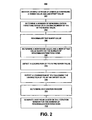
- FIG. 2 a logic flow for renormalization in accordance with one or more embodiments.
- FIG. 3 illustrates a renormalizer system in accordance with one or more embodiments.
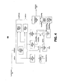
- FIG. 4 illustrates a renormalizer apparatus in accordance with one or more embodiments.
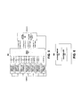
- FIG. 5 illustrates a pattern detector and in-place computation module in accordance with one or more embodiments.
- FIG. 6 illustrates an article of manufacture comprising renormalizer logic in accordance with one or more embodiments.
- renormalization may involve detecting a leading number of '0's in a range value of an input stream of symbols, a run of '1's in an offset value of the input stream of symbols, and a run of '0's following the run of '1' in the offset value.
- a bitstream may be outputted based on an iteration window for a number of renormalization iterations.
- the iteration window may comprise a bit range after the run of '1's in the offset value, and the number of renormalization iterations may be based on the leading number of '0's in the range value.
- the range value may be renormalized by shifting the range value by the leading number of '0's. New range values and new offset values may be determined based on the number of renormalization iterations.
- the offset value may fall in an upper range if significant bits of the offset value comprise a run of '1's in the iteration window and a value of '1' may be outputted to the bitstream.
- the offset value may be reduced by the lowest value of the upper range after an iteration and multiplied to put the offset value back into the upper range.
- the offset value may fall below the upper range during the run of '0's and a value of '0' may be outputted to the bitstream.
- the iteration window may be latched into a register and the number of bits outstanding may be incremented if a last bit in the register comprises a '1'. Otherwise, a value of '0' may be outputted to the bitstream. In some embodiments, a run of '1's followed by one or more '0's may be identified as a particular pattern.
- FIG. 1 illustrates a media processing system 100 in accordance with one or more embodiments.
- the media processing system 100 may comprise various physical and/or logical components for communicating information which may be implemented as hardware, software, or any combination thereof, as desired for a given set of design parameters or performance constraints.
- FIG. 1 may show a limited number of components by way of example, it can be appreciated that a greater or a fewer number of components may be employed for a given implementation.
- the media processing system 100 may be implemented for a PC, consumer electronics (CE), and/or mobile platform as a system within and/or connected to a device such as personal PC, STB, digital TV device, Internet Protocol TV (IPTV) device, digital camera, media player, and/or cellular telephone.
- a device such as personal PC, STB, digital TV device, Internet Protocol TV (IPTV) device, digital camera, media player, and/or cellular telephone.
- IPTV Internet Protocol TV
- Such devices may include, without limitation, a workstation, terminal, server, media appliance, audio/video (A/V) receiver, digital music player, entertainment system, digital TV (DTV) device, high-definition TV (HDTV) device, direct broadcast satellite TV (DBS) device, video on-demand (VOD) device, Web TV device, digital video recorder (DVR) device, digital versatile disc (DVD) device, high-definition DVD (HD-DVD) device, Blu-ray disc (BD) device, video home system (VHS) device, digital VHS device, a gaming console, display device, notebook PC, a laptop computer, portable computer, handheld computer, personal digital assistant (PDA), voice over IP (VoIP) device, combination cellular telephone/PDA, smart phone, pager, messaging device, wireless access point (AP), wireless client device, wireless station (STA), base station (BS), subscriber station (SS), mobile subscriber center (MSC), mobile unit, and so forth.
- A/V audio/video
- DTV digital TV
- HDTV high
- the media processing system 100 may be implemented within and/or connected to a device comprising one more interfaces and/or components for wireless communication such as one or more transmitters, receivers, transceivers, chipsets, amplifiers, filters, control logic, network interface cards (NICs), antennas, and so forth.
- a device comprising one more interfaces and/or components for wireless communication such as one or more transmitters, receivers, transceivers, chipsets, amplifiers, filters, control logic, network interface cards (NICs), antennas, and so forth.
- NICs network interface cards
- an antenna may include, without limitation, an internal antenna, an omni-directional antenna, a monopole antenna, a dipole antenna, an end fed antenna, a circularly polarized antenna, a micro-strip antenna, a diversity antenna, a dual antenna, an antenna array, and so forth.
- the media processing system 100 may form part of a wired communications system, a wireless communications system, or a combination of both.
- the media processing system 100 may be arranged to communicate information over one or more types of wired communication links.
- Examples of a wired communication link may include, without limitation, a wire, cable, bus, printed circuit board (PCB), Ethernet connection, peer-to-peer (P2P) connection, backplane, switch fabric, semiconductor material, twisted-pair wire, co-axial cable, fiber optic connection, and so forth.
- the media processing system 100 also may be arranged to communicate information over one or more types of wireless communication links.
- Examples of a wireless communication link may include, without limitation, a radio channel, satellite channel, television channel, broadcast channel infrared channel, radio-frequency (RF) channel, Wireless Fidelity (WiFi) channel, a portion of the RF spectrum, and/or one or more licensed or license-free frequency bands.
- RF radio-frequency
- WiFi Wireless Fidelity
- the media processing system 100 may be arranged to operate within a network, such as a Wide Area Network (WAN), Local Area Network (LAN), Metropolitan Area Network (MAN), wireless WAN (WWAN), wireless LAN (WLAN), wireless MAN (WMAN), wireless personal area network (WPAN), Worldwide Interoperability for Microwave Access (WiMAX) network, broadband wireless access (BWA) network, the Internet, the World Wide Web, telephone network, radio network, television network, cable network, satellite network such as a direct broadcast satellite (DBS) network, Code Division Multiple Access (CDMA) network, third generation (3G) network such as Wide-band CDMA (WCDMA), fourth generation (4G) network, Time Division Multiple Access (TDMA) network, Extended-TDMA (E-TDMA) cellular radiotelephone network, Global System for Mobile Communications (GSM) network, GSM with General Packet Radio Service (GPRS) systems (GSM/GPRS) network, Synchronous Division Multiple Access (SDMA) network, Time Division Synchronous CDMA (TD-SCDMA
- GSM
- the media processing system 100 may be arranged to communicate one or more types of information, such as media information and control information.
- Media information generally may refer to any data representing content meant for a user, such as image information, video information, audio information, A/V information, graphical information, voice information, textual information, numerical information, alphanumeric symbols, character symbols, and so forth.
- Control information generally may refer to any data representing commands, instructions or control words meant for an automated system. For example, control information may be used to route media information through a system, or instruct a node to process the media information in a certain manner.
- the media and control information may be communicated from and to a number of different devices or networks.
- the media information and control information may be segmented into a series of packets.
- Each packet may comprise, for example, a discrete data set having a fixed or varying size represented in terms of bits or bytes. It can be appreciated that the described embodiments are applicable to any type of communication content or format, such as packets, frames, fragments, cells, windows, units, and so forth.
- the media processing system 100 may communicate information in accordance with one or more protocols.
- a protocol may comprise a set of predefined rules or instructions for managing communication among nodes.
- the media processing system 100 may employ one or more protocols such as medium access control (MAC) protocol, Physical Layer Convergence Protocol (PLCP), Simple Network Management Protocol (SNMP), Asynchronous Transfer Mode (ATM) protocol, Frame Relay protocol, Systems Network Architecture (SNA) protocol, Transport Control Protocol (TCP), Internet Protocol (IP), TCP/IP, X.25, Hypertext Transfer Protocol (HTTP), User Datagram Protocol (UDP), and so forth.
- MAC medium access control
- PLCP Physical Layer Convergence Protocol
- SNMP Simple Network Management Protocol
- ATM Asynchronous Transfer Mode
- Frame Relay protocol Frame Relay protocol
- SNA Systems Network Architecture
- TCP Internet Protocol
- IP Internet Protocol
- TCP/IP Transmission Control Protocol
- HTTP Hypertext Transfer Protocol
- UDP User Datagram Protocol
- the media processing system 100 may communicate information in accordance with one or more standards as promulgated by a standards organization, such as the ITU, the ISO, the IEC, the Institute of Electrical and Electronics Engineers (IEEE), the Internet Engineering Task Force (IETF), and so forth.
- a standards organization such as the ITU, the ISO, the IEC, the Institute of Electrical and Electronics Engineers (IEEE), the Internet Engineering Task Force (IETF), and so forth.
- the media processing system 100 may communicate information according to media processing standards such as, for example, the H.264/AVC standard, the ITU/IEC H.263 standard (Video Coding for Low Bitrate Communication, ITU-T Recommendation H.263v3, published November 2000), MPEG standards (e.g., MPEG-1, MPEG-2, MPEG-4), Digital Video Broadcasting (DVB) terrestrial (DVB-T) standards, DVB satellite (DVB-S or -S2) standards, DVB cable (DVB-C) standards, DVB terrestrial for handhelds (DVB-H), National Television System Committee (NTSC) and Phase Alteration by Line (PAL) standards, Advanced Television Systems Committee (ATSC) standards, Society of Motion Picture and Television Engineers (SMPTE) standards such as the SMPTE 421M or VC-1 standard based on Windows Media Video (WMV) version 9, Digital Transmission Content Protection over Internet Protocol (DTCP-IP) standards, High performance radio Local Area Network (HiperLAN) standards, and so forth.
- media processing standards such as,
- the media processing system 100 may be arranged to receive media content from a media source.
- the media source generally may comprise various devices and/or systems capable of delivering static or dynamic media content to the media processing system 100.
- the media source may comprise or form part of an image acquisition device such as a video camera or mobile device with imaging capabilities.
- the media source also may comprise a multimedia server arranged to provide broadcast or streaming media content.
- the media source may comprise or form part of a media distribution system (DS) or broadcast system such as an over-the-air (OTA) broadcast system, DVB system, radio broadcast system, satellite broadcast system, and so forth.
- DS media distribution system
- OTA over-the-air
- the media source may be implemented within a VOD system or interactive television system that allows users to select, receive, and view video content over a network.
- the media source also may comprise or form part of an IPTV system that delivers digital television content over an IP connection, such as a broadband connection.
- the media processing system 100 may be coupled to the media source through various types of communication channels capable of carrying information signals such as wired communication links, wireless communication links, or a combination of both, as desired for a given implementation.
- the media processing system 100 also may be arranged to receive media content from the media source through various types of components or interfaces.
- the media processing system 100 may be arranged to receive media content through one or more tuners and/or interfaces such as an OpenCable (OC) tuner, NTSC/PAL tuner, tuner/demodulator, point-of-deployment (POD)/DVB common interface (DVB-CI), A/V decoder interface, Ethernet interface, PCI interface, and so forth.
- the media content delivered to the media processing system 100 may comprise various types of information such as image information, audio information, video information, A/V information, and/or other data.
- the media source may be arranged to deliver media content in various formats for use by a device such as a STB, IPTV device, VOD device, media player, and so forth.
- the media content may be delivered as compressed media content to allow the media processing system 100 to efficiently store and/or transfer data.
- the media content may be compressed by employing techniques such as spatial compression using discrete cosine transform (DCT), temporal compression, motion compensation, and quantization.
- Video compression of the media content may be performed, for example, in accordance with standards such as H.264, MPEG-2, MPEG-4, VC-1, and so forth.
- the media content may be delivered as scrambled and/or encrypted media content to prevent unauthorized reception, copying, and/or viewing.
- Video information generally may refer to any data derived from or associated with one or more video images.
- video information may comprise one or more of video data, video sequences, group of pictures (GOP), pictures, images, regions, objects, frames, slices, macroblocks, blocks, pixels, signals (e.g., Y, U, and V), and so forth.
- the values assigned to pixels may comprise real numbers and/or integer numbers.
- the media processing system 100 may be arranged to perform video coding, such as entropy encoding.
- the media processing system 100 may be implemented within and/or coupled to an entropy encoder, such as a CABAC encoder or any other suitable entropy encoder consistent with the described embodiments. While some embodiments may be described as implementing CABAC encoding for purposes of illustration, it can be appreciated that various aspects of the described embodiments may find applicability in other video coding and/or decoding techniques such as variable length coding (VLC), context-based adaptive variable length coding (CAVLC), and so forth.
- VLC variable length coding
- CAVLC context-based adaptive variable length coding
- the media processing system 100 may be arranged to use arithmetic coding according to the H.264/AVC standard and to encode values using a non-integer or fractional number of bits per symbol.
- the media processing system 100 also may be arranged to adaptively adjust to dynamic symbol statistics and to use context modeling based on observed relevant syntax elements.
- the media processing system 100 may be arranged to receive and encode a symbol stream 102 and to output an encoded bitstream 104 comprising a sequence of compressed video bits.
- the symbol stream 102 may comprise symbols for various syntax elements. Examples of syntax elements may include one or more of slice payload data, macroblock type and/or block pattern, intra prediction modes, reference frame indexes, motion vectors, quantized transform coefficients, and so forth.
- the symbol stream 102 may be provided from a quantizer.
- the quantizer may be arranged to quantize transformed (e.g., forward DCT) coefficients and output residue coefficients according to a quantization factor and/or quantization matrix.
- the residue may relate to differences in predicted and/or actual content (e.g., pixels, motion vectors) such as differences between blocks of a current frame and one or more reference frames.
- the media processing system 100 may comprise a renormalizer apparatus 106.
- the renormalizer apparatus may be arranged to optimize the datapath for CABAC encoding and renormalization.
- the renormalizer apparatus 106 may be implemented, for example, to perform high performance renormalization for applications and/or products where a very high throughput is required at lower clock frequencies such as high definition (HD) applications and products (e.g., HD-capable H.264 encoder, multi-stream HD encoder, more than HD resolution encoder (4000x3000 pixels) for digital cinema applications, etc.)
- HD high definition
- HD high definition
- the renormalizer apparatus 106 may comprise a plurality of functional components or modules.
- the modules may be implemented by one or more chips or integrated circuits (ICs) and may comprise, for example, hardware and/or software such as logic (e.g., instructions, data, and/or code) to be executed by a logic device.
- a logic device include, without limitation, a central processing unit (CPU), microcontroller, microprocessor, general purpose processor, dedicated processor, chip multiprocessor (CMP), media processor, digital signal processor (DSP), network processor, co-processor, input/output (I/O) processor, application specific integrated circuit (ASIC), field programmable gate array (FPGA), programmable logic device (PLD), and so forth.
- Executable logic may be stored internally or externally to a logic device on one or more types of computer-readable storage media such as volatile or non-volatile memory, removable or non-removable memory, erasable or non-erasable memory, writeable or re-writeable memory, and so forth.
- the modules may be physically or logically coupled and/or connected by communications media comprising wired communication media, wireless communication media, or a combination of both, as desired for a given implementation.
- the plurality of modules may be implemented as a system-on-a-chip (SOC) by a single chip or integrated circuit (IC). The embodiments are not limited in this context.
- the renormalizer apparatus 106 may receive a symbol stream 102.
- the symbol stream 102 may comprise a range value and an offset value.
- the range value may comprise a nine bit (e.g., B 0 -B 8 ) codIRange value
- the offset value may comprise a ten bit (e.g., B 0 -B 9 ) codILow value.
- the renormalizer apparatus 106 may comprise a lead '0'detection module 108.
- the lead '0' detection module 108 may be arranged to receive the range value codIRange and to detect the leading number of '0's before the first '1' in the range value codIRange from left to right.
- the lead '0' detection module 108 may determine a number of renormalization iterations based on a leading number of '0's in the range value codIRange and may set a renormalization iteration number IterN equal to the leading number of '0's.
- the minimum value of the renormalization iteration number IterN may be 1, and the maximum value of the renormalization iteration number IterN may be 8.
- the renormalizer apparatus 106 may comprise a first shifter and register module 110 and a second shifter and register module 112 coupled to the lead '0' detection module 108.
- the shifter and register modules 110, 112 may be implemented, for example, by barrel shifter logic and registers.
- the first shifter and register module 110 may receive the range value codIRange and the renormalization iteration number IterN as inputs.
- the second shifter and register module 112 may receive the offset value codILow and the renormalization iteration number IterN as inputs.
- the first shifter and register module 110 may be arranged to renormalize the range value codIRange.
- the range value codIRange may comprise a nine bit value (e.g., B 0 -B 8 ), and renormalization of the range value codIRange may be obtained by repeated left shifts until a '1' appears in the bit eight (B 8 ) position.
- the number of shifts ShiftN to renormalize the range value codIRange corresponds to the number of renormalization iterations as well as the leading number of '0's in the range value codIRange.
- the shifter and register modules 110, 112 may be arranged to determine a new range value codIRange and a new offset value codILow to be used for a subsequent step of arithmetic encoding based on the renormalization iteration number IterN.
- codILow codILow ⁇ IterN
- the new codIRange value and the new codILow value may be generated by the shifter and register modules 110, 112 in one cycle.
- the renormalizer apparatus 106 may comprise a subtraction module 116 coupled to the lead '0' detection module 108 and the lead '1' detection module 114.
- the subtraction module 116 may provide the InterNew value to a decision module 118.
- the decision module 118 may end the renormalization loop if the IterNew value is less than or equal to 0.
- the decision module 118 may provide the InterNew value to a subtraction module 120 coupled to a lead '0' detection module 122.
- the lead '0' detection module 122 may set a leading run of '0's value LeadZeroN to the number of '0's from the bit position B 9-OneWindow to bit position B 0 of the offset value codILow.
- the subtraction module 120 may provide the InterEffective value to a decision module 124. If the run length is greater than effective iteration value IterEffective (e.g., IterEffective ⁇ 0), the decision module 124 may instruct that a value of '0' be put into the bitsteam for a number of times corresponding to the absolute value of the effective iteration value IterEffective.
- Effective iteration value IterEffective e.g., IterEffective ⁇ 0
- the decision module 124 may be coupled to an interloop module 126.
- the interloop module 126 may receive the InterEffective value and the codILow value and latch the bit range after the run of '1's in the offset value codILow into a register (e.g., eight bit register A[8:0]).
- the renormalizer apparatus 106 may comprise a finite state machine (FSM) module 128.
- the FSM module 128 may be coupled to the lead '1' detection module 114, the decision module 124, and the interloop module 126.
- the FSM module may receive a PutBit(1) instruction and a number of PutBit(1) calls instruction from the lead '1' detection module 114.
- the FSM module may receive a PutBit(0) instruction and a number of PutBit(0) calls instruction from the decision module 124.
- the FSM module 128 may receive a PutBit(x) instruction and a number of PutBit(x) calls instruction from the interloop module 126.
- the FSM module 128 also may receive a bitsOutstanding value from a register 130 coupled to a trail '1' detection module 132 arranged to detect a sequence of '1's in the codILow value.
- the FSM module 128 may be arranged to provide a PutBit(x) instruction, a number of PutBit(x) calls instruction, and bitsOutstanding value to a bit generation module 134.
- the bit generation module 134 may arranged to output the bitstream 104 in response to the PutBit(x) instruction, a number of PutBit(x) calls instruction, and bitsOutstanding value received from the FSM module 128.
- the bit generation module 130 may be arranged to generate the bitstream 104 as follows.
- the offset value codILow may fall within a 512-1023 range when entering the renormalization loop. For example, if bit positions B 9 and below contains a run of '1's in the iteration window bit range IterWindow, then after every iteration, the offset value codILow is reduced by 512 and multiplied by 2 to put the offset value codILow back in the 512-1023 range while outputting '1' to the bitstream. In various implementations, during renormalization for the number of renormalization iterations IterN, once the codILow value falls to the 0-255 range, it may never again fall in 512-1023 range.
- the offset value codILow may fall in a 0-511 range during the run of '0's, and a value of '0' may be outputted to the bitstream.
- the iteration window comprising the bits after the run of '1's in the offset value codILow is latched into a register (e.g., eight bit register A[8:0]).
- a register e.g., eight bit register A[8:0]
- the last bit in the register is a '1'
- the number of bits outstanding is incremented (e.g., bitsOutstanding++). Otherwise, a value of '0'is put into the bitstream and the register is left shifted by 1 (e.g., A[8:0] ⁇ 1). It can be appreciated that it may take up to 8 clock cycles to complete the iteration window.
- FIG. 2 illustrates a logic flow 200 for renormalization in accordance with one or more embodiments.
- the logic flow 200 may be performed by various systems, devices, units, and/or components and may be implemented as hardware, software, and/or any combination thereof, as desired for a given set of design parameters or performance constraints.
- the logic flow 200 may be implemented, for example, by the renormalizer apparatus 106 (e.g., multi-cycle renormalization unit) illustrated in FIG. 1 .
- the embodiments, however, are not limited in this context.
- the logic flow 200 may comprise receiving an input stream of symbols comprising a range value and an offset value (block 202).
- the range value may comprise a nine bit (e.g., B 0 -B 8 ) codIRange value
- the offset value may comprise a ten bit (e.g., B 0 -B 9 ) codILow value.
- the logic flow 200 may comprise determining a number of renormalization iterations based on a leading number of '0's in the range value (block 204).
- the leading number of '0's before the first '1' in the range value codIRange is detected from left to right.
- a renormalization iteration number IterN is set based on the leading number of '0's.
- the minimum value of the renormalization iteration number IterN may be 1, and the maximum value of the renormalization iteration number IterN may be 8.
- the logic flow may comprise renormalizing the range value (block 206).
- the range value codIRange may comprise a nine bit value (e.g., B 0 -B 8 ), and renormalization of the range value codIRange may be obtained by repeated left shifts until a '1' appears in the bit eight (B 8 ) position.
- the number of shifts ShiftN to renormalize the range value codIRange corresponds to the number of renormalization iterations as well as the leading number of '0's in the range value.
- the logic flow 200 may comprise determining a new range value and a new offset value to be used for a subsequent step of arithmetic encoding based on the number of renormalization iterations (block 208).
- the new codIRange value and the new codILow value may be generated in one cycle.
- the logic flow 200 may comprise detecting a leading run of '1's in the range value (block 210).
- the logic flow 200 may comprise detecting a leading run of '0's following the leading run of '1's in the offset value (block 212).
- a leading run of '0's value LeadZeroN may be determined by detecting a leading run of '0's from the bit position B 9-OneWindow to bit position B 0 of the offset value codILow.
- the logic flow 200 may comprise determining an iteration window (block 214).
- the logic flow 200 may comprise generating a bitstream based on the iteration window for the number of renormalization iterations (block 216). If there are consecutive '1's in the most significant bit positions (e.g., starting with bit position B 9 ) of the offset value codIRange, the offset value codILow may fall within a 512-1023 range when entering the renormalization loop. For example, if bit positions B 9 and below contains a run of '1's in the iteration window bit range IterWindow, then after every iteration, the offset value codILow is reduced by 512 and multiplied by 2 to put the offset value codILow back in the 512-1023 range while outputting '1' to the bitstream. In various implementations, during renormalization for the number of renormalization iterations IterN, once the codILow value falls to the 0-255 range, it may never again fall in 512-1023 range.
- the offset value codILow may fall in a 0-511 range during the run of '0's, and a value of '0' may be outputted to the bitstream.
- the iteration window comprising the bits after the run of '1's in the offset value codILow is latched into a register (e.g., eight bit register A[8:0]).
- a register e.g., eight bit register A[8:0]
- the last bit in the register is a '1'
- the number of bits outstanding is incremented (e.g., bitsOutstanding++). Otherwise, a value of '0'is put into the bitstream and the register is left shifted by 1 (e.g., A[8:0] ⁇ 1). It can be appreciated that it may take up to 8 clock cycles to complete the iteration window.
- the number of iterations (IterN) for the renormalization loop is equal to the leading number of '0's before the first '1' in the codIRange value from left to right. Renormalization of codIRange may be obtained by repeated left shifts until a '1' appears in bit position B 8 .
- codILow renormalization iterations (IterN) once the value falls to 0-255 range, it may never again fall in 512-1023 range. The only possibility for codILow to fall in 512-1023 range is when there are consecutive '1's in the most significant positions starting from bit position B 9 while entering the renormalization loop.
- FIG. 3 illustrates a renormalizer system 300 in accordance with one or more cmbodimcnts.
- the renormalizer system 300 may be used to implement the logic flow 200 of FIG. 2 .
- the embodiments, however, are not limited in this context.
- the renormalizer system 300 may be arranged to receive and encode a symbol stream 302 and to output an encoded bitstream 304 comprising a sequence of compressed video bits.
- the renormalizer system 300 may comprise a plurality of multi-cycle renormalizer units 306-1-X, where X represents any positive integer value consistent with the described embodiments.
- each multi-cycle renormalizer unit 306-1-X may be implemented by the renormalizer apparatus 106 of FIG. 1 .
- the embodiments, however, are not limited in this context.
- renormalizer system 300 may comprise eight multi-cycle renormalization units 306-1-8 to implement a single-cycle renormalization.
- the renormalizer system 300 may comprise a multi-cycle architecture to achieve single clock performance of one bit per clock.
- the renormalizer system 300 may comprise a scheduler module 308 coupled to the multi-cycle renormalization units 306-1-8.
- the scheduler module 308 may be arranged to distribute the incoming values to be renormalized to each of the multi-cycle renormalizer units 306-1-8 in a sequence.
- the scheduler modules 308 may return to the first multi-cycle renormalizer unit 306-1. Even assuming a worst case of 8 cycles to renormalize each value, at the 9th clock, the first multi-cycle renormalizer unit 306-1 is ready to receive the next value. Similarly, at the 10th clock, the second multi-cycle renormalizer unit 306-2 is ready to receive the next value, and so forth.
- the drainer and bitstream composer module 312 may be implemented as a first-in-first out (FIFO) drainer to drain the bits from output of each multi-cycle renormalizer unit 306-1-8 in a sequential manner to compose the final bitstream.
- FIFO first-in-first out
- one or more bits can be generated at each of the iterations by the drainer and bitstream composer module 312. Sometimes, however, no bits are generated. To take into account such traffic bursts, a bitstream buffer 314 may be provided at the output to absorb this burstiness.
- the drainer and bitstream composer module 312 may comprise a 128 bit register which can dump 128 bits in a clock to the bitstream.
- the renormalizer system 300 may provide a throughput of 1 bit /cycle to 10 bits/clock.
- the renormalizer system 300 may be arranged to receive one codILow value for every clock and create a bitstream without any back pressure.
- the renormalizer system 300 may achieve a 50 Mbps throughput using a 50 MHz clock.
- the architecture of the renormalizer system 300 is highly pipelined and scalable both from clock frequency and performance perspectives. For example, the average encoding throughput may be 10 bits/cycle, and at 250 MHz clock, the renormalizer system 300 may encode a bitstream at 2.5 Gbps.
- FIG. 4 illustrates a renormalizer apparatus 400 in accordance with one or more embodiments.
- the renormalizer apparatus 400 may be used to implement the logic flow 200 of FIG. 2 .
- the embodiments, however, are not limited in this context.
- the renormalizer apparatus 400 may receive a symbol stream 402 comprising a range value and an offset value.
- the range value may comprise a nine bit (e.g., B 0 -B 8 ) codIRange value
- the offset value may comprise a ten bit (e.g., B 0 -B 9 ) codILow value.
- the renormalizer apparatus 400 may be implemented as a single-cycle renormalizer capable of outputting a one bit per clock bitstream 404.
- the renormalizer apparatus 400 may comprise a lead '0'detection module 408, a first shifter and register module 410, a second shifter and register module 412, a lead '1'detection module 414, a subtraction module 416, a decision module 418, a subtraction module 420, a lead '0' detection module 422, and a decision module 424.
- a lead '0'detection module 408 a first shifter and register module 410, a second shifter and register module 412, a lead '1'detection module 414, a subtraction module 416, a decision module 418, a subtraction module 420, a lead '0' detection module 422, and a decision module 424.
- such elements may be implemented substantially as described above in connection with the renormalizer apparatus 106 of FIG. 1 .
- the codILow value is sent through the lead '1' detection module 414 and the decision module 424 which handle two
- the renormalizer apparatus 400 may comprise a pattern detector and in-place computation module 426.
- the output of the decision module 424 e.g., SourceReg, OutputReg
- the pattern detector and in-place computation module 426 which completes the renormalization flow.
- the codILow value bits are modified. No shifting of bits is done any stage. Therefore, all the bit manipulation operations can be completed in one cycle.
- the pattern detector and in-place computation module 402 may be arranged to identify a run of '1's followed by one or more '0's as a particular pattern.
- Detected runs of '1's may comprise several possible patterns such as "10" to "11111110". Additionally, for each pattern there are several positions possible. For the "10" pattern, for example, there are seven positions possible starting from B 7 to B 1 . A sequence of eight '1's may be detected using the trail '1' detection module 432.
- specific patterns require special treatment. For example, if a run of '1's is found, no bits are dumped into the bitstream until a breaking condition is found.
- the breaking condition is the occurrence of either a zero in the current codILow value to be encoded or zero/one in the next codILow value to be encoded.
- the pattern detector and in-place computation module 426 may be arranged to prioritize certain patterns. For example, if a pattern "10" and a pattern "110" are both asserted for the same bit ending positions, the pattern "110" may be given higher priority.
- the pattern detector and in-place computation module 426 may be arranged to perform in-place computation where patterns are bit reversed. For example, a codILow value of 11011010 is converted to 01101101, which in turn, gets written into the bitstream.
- the renormalizer apparatus 400 may implement a single cycle renormalizer at the cost of extra die area.
- the renormalizer apparatus 400 may provide a throughput of 1 bit /cycle to 10 bits/clock. Accordingly, the renormalizer apparatus 400 may achieve a 50 Mbps throughput using a 50 MHz clock or 5 MHz clock. For a system running at 25 MHz clock, an average encoding throughput of 250 Mbps may be achieved.
- the architecture of the renormalizer apparatus 400 is highly pipelined and scalable both from clock frequency and performance perspectives. For example, the average encoding throughput may be 10 bits/cycle, and at 250 MHz clock, the renormalizer apparatus 400 may encode a bitstream at 2.5 Gbps.
- FIG. 5 illustrates a pattern detector and in-place computation module 500 in accordance with one or more embodiments.
- the pattern detector and in-place computation module 500 may be implemented, for example, within the renormalizer apparatus 400 of FIG. 4 .
- the embodiments, however, are not limited in this context.
- the pattern detector and in-place computation module 500 may comprise seven pattern detectors 502-1-7 coupled to a position resolver 504. Detected runs of ones may comprise several possible patterns such as "10" to "11111110". Additionally, for each pattern there are several positions possible. For the "10" pattern, for example, there are seven positions possible starting from B 7 to B 1 . In this embodiment, the seven pattern detectors 502-1-7 may correspond to seven possible patterns comprising runs of ones "10" to "11111110".
- signals from each of the pattern detectors 502-1-7 are sent to the position resolver 504.
- the pattern "110” may be given higher priority.
- the position resolver 504 may be arranged to feed the final positions and runs to an in-place computation unit 506 where patterns are bit reversed. For example, a codILow value of 11011010 is converted to 01101101, which in turn, gets written into the bitstream.
- FIG. 6 illustrates one embodiment of an article of manufacture 600.
- the article 600 may comprise a storage medium 602 to store renormalizer logic 604 for performing various operations in accordance with the described embodiments.
- the article 600 may be implemented by various systems, components, and/or modules.
- the article 600 and/or storage medium 602 may include one or more types of computer-readable storage media capable of storing data, including volatile memory or, non-volatile memory, removable or non-removable memory, erasable or non-erasable memory, writeable or re-writeable memory, and so forth.
- Examples of a computer-readable storage medium may include, without limitation, random-access memory (RAM), Dynamic RAM (DRAM), Synchronous DRAM (SDRAM), Double-Data-Rate RAM (DDR RAM), DDR SDRAM, static RAM (SRAM), read-only memory (ROM), programmable ROM (PROM), erasable programmable ROM (EPROM), electrically erasable programmable ROM (EEPROM), Compact Disk ROM (CD-ROM), Compact Disk Recordable (CD-R), Compact Disk Rewriteable (CD-RW), flash memory (e.g., NOR or NAND flash memory), content addressable memory (CAM), polymer memory (e.g., ferroelectric polymer memory), phase-change memory (e.g., ovonic memory), ferroelectric memory, silicon-oxide-nitride-oxide-silicon (SON OS) memory, disk (e.g., floppy disk, hard drive, optical disk, magnetic disk, magneto-optical disk), or card (e.g.,
- the article 600 and/or storage medium 602 may store renormalizer logic 604 comprising instructions, data, and/or code that, if executed, cause a computer or computer system to perform a method and/or operations in accordance with the described embodiments.
- renormalizer logic 604 comprising instructions, data, and/or code that, if executed, cause a computer or computer system to perform a method and/or operations in accordance with the described embodiments.
- Such a computer or computer system may include, for example, any suitable processing platform, computing platform, computing device, processing device, computing system, processing system, processor, or the like, and may be implemented using any suitable combination of hardware and/or software.
- the renormalizer logic 604 may comprise, or be implemented as, software, a software module, an application, a program, a subroutine, instructions, an instruction set, computing code, words, values, symbols or combination thereof.
- the instructions may include any suitable type of code, such as source code, compiled code, interpreted code, executable code, static code, dynamic code, and the like.
- the instructions may be implemented according to a predefined computer language, manner or syntax, for instructing a processor to perform a certain function.
- the instructions may be implemented using any suitable high-level, low-level, object-oriented, visual, compiled and/or interpreted programming language, such as C, C++, Java, BASIC, Perl, Matlab, Pascal, Visual BASIC, assembly language, machine code, and so forth. The embodiments are not limited in this context.
- Various embodiments may comprise one or more elements.
- An element may comprise any structure arranged to perform certain operations.
- Each element may be implemented as hardware, software, or any combination thereof, as desired for a given set of design and/or performance constraints.
- an embodiment may be described with a limited number of elements in a certain topology by way of example, the embodiment may include more or less elements in alternate topologies as desired for a given implementation.
- any reference to "one embodiment” or “an embodiment” means that a particular feature, structure, or characteristic described in connection with the embodiment is included in at least one embodiment.
- the appearances of the phrase “in one embodiment” in the specification are not necessarily all referring to the same embodiment.
- exemplary functional components or modules may be implemented by one or more hardware components, software components, and/or combination thereof.
- the functional components and/or modules may be implemented, for example, by logic (e.g., instructions, data, and/or code) to be executed by a logic device (e.g., processor).
- logic e.g., instructions, data, and/or code
- Such logic may be stored internally or externally to a logic device on one or more types of computer-readable storage media.
- FIG. 1 Some of the figures may include a flow diagram. Although such figures may include a particular logic flow, it can be appreciated that the logic flow merely provides an exemplary implementation of the general functionality. Further, the logic flow does not necessarily have to be executed in the order presented unless otherwise indicated. In addition, the logic flow may be implemented by a hardware element, a software element executed by a processor, or any combination thereof.
- processing refers to the action and/or processes of a computer or computing system, or similar electronic computing device, that manipulates and/or transforms data represented as physical quantities (e.g., electronic) within registers and/or memories into other data similarly represented as physical quantities within the memories, registers or other such information storage, transmission or display devices.
- physical quantities e.g., electronic
- Coupled and “connected” along with their derivatives. These terms are not intended as synonyms for each other. For example, some embodiments may be described using the terms “connected” and/or “coupled” to indicate that two or more elements are in direct physical or electrical contact with each other. The term “coupled,” however, may also mean that two or more elements are not in direct contact with each other, but yet still co-operate or interact with each other. With respect to software elements, for example, the term “coupled” may refer to interfaces, message interfaces, API, exchanging messages, and so forth.
Landscapes
- Engineering & Computer Science (AREA)
- Multimedia (AREA)
- Signal Processing (AREA)
- Theoretical Computer Science (AREA)
- Computing Systems (AREA)
- Compression Or Coding Systems Of Tv Signals (AREA)
Applications Claiming Priority (2)
| Application Number | Priority Date | Filing Date | Title |
|---|---|---|---|
| US11/618,551 US7561082B2 (en) | 2006-12-29 | 2006-12-29 | High performance renormalization for binary arithmetic video coding |
| EP20070869391 EP2127383A4 (de) | 2006-12-29 | 2007-12-17 | Hochleistungs-renormalisierung für videokodierungen mit binärer arithmetik |
Related Parent Applications (1)
| Application Number | Title | Priority Date | Filing Date |
|---|---|---|---|
| EP07869391.8 Division | 2007-12-17 |
Publications (2)
| Publication Number | Publication Date |
|---|---|
| EP2651133A2 true EP2651133A2 (de) | 2013-10-16 |
| EP2651133A3 EP2651133A3 (de) | 2013-11-27 |
Family
ID=39585723
Family Applications (2)
| Application Number | Title | Priority Date | Filing Date |
|---|---|---|---|
| EP13003537.1A Withdrawn EP2651133A3 (de) | 2006-12-29 | 2007-12-17 | Hochleistungsfähige Renormierung für binäre arithmetische Videokodierung |
| EP20070869391 Ceased EP2127383A4 (de) | 2006-12-29 | 2007-12-17 | Hochleistungs-renormalisierung für videokodierungen mit binärer arithmetik |
Family Applications After (1)
| Application Number | Title | Priority Date | Filing Date |
|---|---|---|---|
| EP20070869391 Ceased EP2127383A4 (de) | 2006-12-29 | 2007-12-17 | Hochleistungs-renormalisierung für videokodierungen mit binärer arithmetik |
Country Status (5)
| Country | Link |
|---|---|
| US (1) | US7561082B2 (de) |
| EP (2) | EP2651133A3 (de) |
| CN (2) | CN101573979B (de) |
| TW (1) | TWI364991B (de) |
| WO (1) | WO2008082941A1 (de) |
Families Citing this family (14)
| Publication number | Priority date | Publication date | Assignee | Title |
|---|---|---|---|---|
| US7561082B2 (en) | 2006-12-29 | 2009-07-14 | Intel Corporation | High performance renormalization for binary arithmetic video coding |
| US8416857B2 (en) | 2007-03-29 | 2013-04-09 | James Au | Parallel or pipelined macroblock processing |
| US8837575B2 (en) | 2007-03-29 | 2014-09-16 | Cisco Technology, Inc. | Video processing architecture |
| US8422552B2 (en) * | 2007-03-29 | 2013-04-16 | James Au | Entropy coding for video processing applications |
| US8369411B2 (en) | 2007-03-29 | 2013-02-05 | James Au | Intra-macroblock video processing |
| US9648325B2 (en) | 2007-06-30 | 2017-05-09 | Microsoft Technology Licensing, Llc | Video decoding implementations for a graphics processing unit |
| US7714753B2 (en) * | 2007-12-11 | 2010-05-11 | Intel Corporation | Scalable context adaptive binary arithmetic coding |
| CN101500164B (zh) * | 2008-12-31 | 2011-09-28 | 深圳市同洲电子股份有限公司 | 算术编码的打包输出的方法和装置 |
| EP2273495A1 (de) * | 2009-07-07 | 2011-01-12 | TELEFONAKTIEBOLAGET LM ERICSSON (publ) | System zur Verarbeitung digitaler Audiosignale |
| US9069726B2 (en) | 2012-12-12 | 2015-06-30 | Microsoft Technology Licensing, Llc | Iteratively calculating standard deviation for streamed data |
| US9455743B2 (en) | 2014-05-27 | 2016-09-27 | Qualcomm Incorporated | Dedicated arithmetic encoding instruction |
| CN104038767B (zh) * | 2014-06-05 | 2017-06-27 | 宁波工程学院 | 一种兼容cabac的加密域h.264/avc视频数据隐藏方法 |
| US10547869B2 (en) | 2017-12-08 | 2020-01-28 | Google Llc | Template-based entropy coding of quantized transform coefficients |
| US10609421B2 (en) | 2018-07-12 | 2020-03-31 | Google Llc | Context derivation for coefficient coding |
Family Cites Families (8)
| Publication number | Priority date | Publication date | Assignee | Title |
|---|---|---|---|---|
| US6748410B1 (en) * | 1997-05-04 | 2004-06-08 | M-Systems Flash Disk Pioneers, Ltd. | Apparatus and method for modular multiplication and exponentiation based on montgomery multiplication |
| EP0895361A3 (de) | 1997-07-31 | 2000-03-15 | AT&T Corp. | Z-Kodierer: schneller adaptiver arithmetischer Kodierer |
| US6825782B2 (en) | 2002-09-20 | 2004-11-30 | Ntt Docomo, Inc. | Method and apparatus for arithmetic coding and termination |
| US6876317B2 (en) * | 2003-05-30 | 2005-04-05 | Texas Instruments Incorporated | Method of context based adaptive binary arithmetic decoding with two part symbol decoding |
| KR100624432B1 (ko) | 2004-08-05 | 2006-09-19 | 삼성전자주식회사 | 내용 기반 적응적 이진 산술 복호화 방법 및 장치 |
| CN100373840C (zh) * | 2005-04-01 | 2008-03-05 | 东南大学 | 归一化迭代软干扰抵消信号检测方法和装置 |
| KR100694098B1 (ko) * | 2005-04-04 | 2007-03-12 | 한국과학기술원 | 산술 복호 방법 및 그 장치 |
| US7561082B2 (en) | 2006-12-29 | 2009-07-14 | Intel Corporation | High performance renormalization for binary arithmetic video coding |
-
2006
- 2006-12-29 US US11/618,551 patent/US7561082B2/en not_active Expired - Fee Related
-
2007
- 2007-11-26 TW TW096144754A patent/TWI364991B/zh not_active IP Right Cessation
- 2007-12-17 WO PCT/US2007/087823 patent/WO2008082941A1/en not_active Ceased
- 2007-12-17 CN CN2007800489980A patent/CN101573979B/zh not_active Expired - Fee Related
- 2007-12-17 CN CN201110134237.5A patent/CN102158708B/zh not_active Expired - Fee Related
- 2007-12-17 EP EP13003537.1A patent/EP2651133A3/de not_active Withdrawn
- 2007-12-17 EP EP20070869391 patent/EP2127383A4/de not_active Ceased
Non-Patent Citations (1)
| Title |
|---|
| None |
Also Published As
| Publication number | Publication date |
|---|---|
| US7561082B2 (en) | 2009-07-14 |
| EP2651133A3 (de) | 2013-11-27 |
| EP2127383A1 (de) | 2009-12-02 |
| CN101573979A (zh) | 2009-11-04 |
| CN102158708B (zh) | 2014-03-05 |
| CN102158708A (zh) | 2011-08-17 |
| WO2008082941A1 (en) | 2008-07-10 |
| CN101573979B (zh) | 2011-07-06 |
| TWI364991B (en) | 2012-05-21 |
| TW200833122A (en) | 2008-08-01 |
| US20080162911A1 (en) | 2008-07-03 |
| EP2127383A4 (de) | 2011-07-27 |
Similar Documents
| Publication | Publication Date | Title |
|---|---|---|
| EP2651133A2 (de) | Hochleistungsfähige Renormierung für binäre arithmetische Videokodierung | |
| US12425619B2 (en) | CABAC decoder with decoupled arithmetic decoding and inverse binarization | |
| US7932843B2 (en) | Parallel CABAC decoding for video decompression | |
| CN101176089B (zh) | 使用多线程单指令多数据处理并行执行媒体编码 | |
| EP2103142B1 (de) | Bewegungserkennung für videoverarbeitung | |
| US10291913B2 (en) | Entropy encoder, video encoder including the same and electronic system including the same | |
| US7835587B2 (en) | Method and apparatus for local standard deviation based histogram equalization for adaptive contrast enhancement | |
| US20190356911A1 (en) | Region-based processing of predicted pixels | |
| US20130208797A1 (en) | Image encoding/decoding system and associated method | |
| US11509940B1 (en) | Video apparatus with reduced artifact and memory storage for improved motion estimation |
Legal Events
| Date | Code | Title | Description |
|---|---|---|---|
| PUAI | Public reference made under article 153(3) epc to a published international application that has entered the european phase |
Free format text: ORIGINAL CODE: 0009012 |
|
| 17P | Request for examination filed |
Effective date: 20130726 |
|
| AC | Divisional application: reference to earlier application |
Ref document number: 2127383 Country of ref document: EP Kind code of ref document: P |
|
| AK | Designated contracting states |
Kind code of ref document: A2 Designated state(s): AT BE BG CH CY CZ DE DK EE ES FI FR GB GR HU IE IS IT LI LT LU LV MC MT NL PL PT RO SE SI SK TR |
|
| PUAL | Search report despatched |
Free format text: ORIGINAL CODE: 0009013 |
|
| AK | Designated contracting states |
Kind code of ref document: A3 Designated state(s): AT BE BG CH CY CZ DE DK EE ES FI FR GB GR HU IE IS IT LI LT LU LV MC MT NL PL PT RO SE SI SK TR |
|
| RIC1 | Information provided on ipc code assigned before grant |
Ipc: H04N 7/26 20060101AFI20131021BHEP Ipc: H03M 7/40 20060101ALI20131021BHEP |
|
| 17Q | First examination report despatched |
Effective date: 20131112 |
|
| STAA | Information on the status of an ep patent application or granted ep patent |
Free format text: STATUS: THE APPLICATION HAS BEEN WITHDRAWN |
|
| 18W | Application withdrawn |
Effective date: 20140313 |