EP2651092A2 - Système et procédé pour determiner la presedence des empreintes digitales correspondants dans une historique de compression - Google Patents
Système et procédé pour determiner la presedence des empreintes digitales correspondants dans une historique de compression Download PDFInfo
- Publication number
- EP2651092A2 EP2651092A2 EP20120190298 EP12190298A EP2651092A2 EP 2651092 A2 EP2651092 A2 EP 2651092A2 EP 20120190298 EP20120190298 EP 20120190298 EP 12190298 A EP12190298 A EP 12190298A EP 2651092 A2 EP2651092 A2 EP 2651092A2
- Authority
- EP
- European Patent Office
- Prior art keywords
- data
- appliance
- network
- compression
- client
- Prior art date
- Legal status (The legal status is an assumption and is not a legal conclusion. Google has not performed a legal analysis and makes no representation as to the accuracy of the status listed.)
- Granted
Links
Images


Classifications
-
- H—ELECTRICITY
- H03—ELECTRONIC CIRCUITRY
- H03M—CODING; DECODING; CODE CONVERSION IN GENERAL
- H03M7/00—Conversion of a code where information is represented by a given sequence or number of digits to a code where the same, similar or subset of information is represented by a different sequence or number of digits
- H03M7/30—Compression; Expansion; Suppression of unnecessary data, e.g. redundancy reduction
- H03M7/3084—Compression; Expansion; Suppression of unnecessary data, e.g. redundancy reduction using adaptive string matching, e.g. the Lempel-Ziv method
- H03M7/3088—Compression; Expansion; Suppression of unnecessary data, e.g. redundancy reduction using adaptive string matching, e.g. the Lempel-Ziv method employing the use of a dictionary, e.g. LZ78
-
- H—ELECTRICITY
- H04—ELECTRIC COMMUNICATION TECHNIQUE
- H04L—TRANSMISSION OF DIGITAL INFORMATION, e.g. TELEGRAPHIC COMMUNICATION
- H04L67/00—Network arrangements or protocols for supporting network services or applications
- H04L67/2866—Architectures; Arrangements
- H04L67/2876—Pairs of inter-processing entities at each side of the network, e.g. split proxies
-
- H—ELECTRICITY
- H04—ELECTRIC COMMUNICATION TECHNIQUE
- H04L—TRANSMISSION OF DIGITAL INFORMATION, e.g. TELEGRAPHIC COMMUNICATION
- H04L67/00—Network arrangements or protocols for supporting network services or applications
- H04L67/2866—Architectures; Arrangements
- H04L67/2885—Hierarchically arranged intermediate devices, e.g. for hierarchical caching
-
- H—ELECTRICITY
- H04—ELECTRIC COMMUNICATION TECHNIQUE
- H04L—TRANSMISSION OF DIGITAL INFORMATION, e.g. TELEGRAPHIC COMMUNICATION
- H04L67/00—Network arrangements or protocols for supporting network services or applications
- H04L67/50—Network services
- H04L67/56—Provisioning of proxy services
-
- H—ELECTRICITY
- H04—ELECTRIC COMMUNICATION TECHNIQUE
- H04L—TRANSMISSION OF DIGITAL INFORMATION, e.g. TELEGRAPHIC COMMUNICATION
- H04L67/00—Network arrangements or protocols for supporting network services or applications
- H04L67/50—Network services
- H04L67/56—Provisioning of proxy services
- H04L67/565—Conversion or adaptation of application format or content
- H04L67/5651—Reducing the amount or size of exchanged application data
-
- H—ELECTRICITY
- H04—ELECTRIC COMMUNICATION TECHNIQUE
- H04L—TRANSMISSION OF DIGITAL INFORMATION, e.g. TELEGRAPHIC COMMUNICATION
- H04L67/00—Network arrangements or protocols for supporting network services or applications
- H04L67/50—Network services
- H04L67/56—Provisioning of proxy services
- H04L67/568—Storing data temporarily at an intermediate stage, e.g. caching
-
- H—ELECTRICITY
- H04—ELECTRIC COMMUNICATION TECHNIQUE
- H04L—TRANSMISSION OF DIGITAL INFORMATION, e.g. TELEGRAPHIC COMMUNICATION
- H04L69/00—Network arrangements, protocols or services independent of the application payload and not provided for in the other groups of this subclass
- H04L69/04—Protocols for data compression, e.g. ROHC
-
- H—ELECTRICITY
- H04—ELECTRIC COMMUNICATION TECHNIQUE
- H04L—TRANSMISSION OF DIGITAL INFORMATION, e.g. TELEGRAPHIC COMMUNICATION
- H04L69/00—Network arrangements, protocols or services independent of the application payload and not provided for in the other groups of this subclass
- H04L69/22—Parsing or analysis of headers
-
- H—ELECTRICITY
- H04—ELECTRIC COMMUNICATION TECHNIQUE
- H04L—TRANSMISSION OF DIGITAL INFORMATION, e.g. TELEGRAPHIC COMMUNICATION
- H04L69/00—Network arrangements, protocols or services independent of the application payload and not provided for in the other groups of this subclass
- H04L69/14—Multichannel or multilink protocols
Definitions
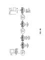
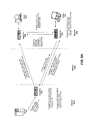
- the network optimization appliance 200 is designed, configured or adapted to optimize Wide Area Network (WAN) network traffic.
- a first appliance 200 works in conjunction or cooperation with a second appliance 200' to optimize network traffic.
- a first appliance 200 may be located between a branch office and a WAN connection while the second appliance 200' is located between the WAN and a corporate Local Area Network (LAN).
- the appliances 200 and 200' may work together to optimize the WAN related network traffic between a client in the branch office and a server on the corporate LAN.
- network 104 may be a private network and network 104' and/or network 104" a public network. In another embodiment, networks 104, 104', 104" may be private networks. In some embodiments, clients 102 may be located at a branch office of a corporate enterprise communicating via a WAN connection over the network 104 to the servers 106 located on a corporate LAN in a corporate data center.
- the servers 106 within each farm 38 can be heterogeneous. One or more of the servers 106 can operate according to one type of operating system platform (e.g., WINDOWS NT, manufactured by Microsoft Corp. of Redmond, Washington), while one or more of the other servers 106 can operate on according to another type of operating system platform (e.g., Unix or Linux).
- the servers 106 of each farm 38 do not need to be physically proximate to another server 106 in the same farm 38.
- the group of servers 106 logically grouped as a farm 38 may be interconnected using a wide-area network (WAN) connection or metropolitan-area network (MAN) connection.
- WAN wide-area network
- MAN metropolitan-area network
- a client 102 communicates with a server 106.
- the client 102 communicates directly with one of the servers 106 in a farm 38.
- the client 102 executes a program neighborhood application to communicate with a server 106 in a farm 38.
- the server 106 provides the functionality of a master node.
- the client 102 communicates with the server 106 in the farm 38 through a network 104. Over the network 104, the client 102 can, for example, request execution of various applications hosted by the servers 106a-106n in the farm 38 and receive output of the results of the application execution for display.
- only the master node provides the functionality required to identify and provide address information associated with a server 106' hosting a requested application.
- a server 106 provides functionality of a web server.
- the server 106a receives requests from the client 102, forwards the requests to a second server 106b and responds to the request by the client 102 with a response to the request from the server 106b.
- the server 106 acquires an enumeration of applications available to the client 102 and address information associated with a server 106 hosting an application identified by the enumeration of applications.
- the server 106 presents the response to the request to the client 102 using a web interface.
- the client 102 communicates directly with the server 106 to access the identified application.
- the client 102 receives application output data, such as display data, generated by an execution of the identified application on the server 106.
- the appliance 200 may be deployed as a single appliance or single proxy on the network 104.
- the appliance 200 may be designed, constructed or adapted to perform WAN optimization techniques discussed herein without a second cooperating appliance 200'.
- a single appliance 200 may be deployed with one or more second appliances 205.
- a WAN acceleration first appliance 200 such as a Citrix WANScaler appliance
- a LAN accelerating or Application Firewall second appliance 205 such as a Citrix NetScaler appliance.
- the central processing unit 101 is any logic circuitry that responds to and processes instructions fetched from the main memory unit 122.
- the central processing unit is provided by a microprocessor unit, such as: those manufactured by Intel Corporation of Mountain View, California; those manufactured by Motorola Corporation of Schaumburg, Illinois; those manufactured by Transmeta Corporation of Santa Clara, California; the RS/6000 processor, those manufactured by International Business Machines of White Plains, New York; or those manufactured by Advanced Micro Devices of Sunnyvale, California.
- the computing device 100 may be based on any of these processors, or any other processor capable of operating as described herein.
- FIG. 1D depicts an embodiment in which the main processor 101 communicates directly with cache memory 140 via a secondary bus, sometimes referred to as a backside bus.
- the main processor 101 communicates with cache memory 140 using the system bus 150.
- Cache memory 140 typically has a faster response time than main memory 122 and is typically provided by SRAM, BSRAM, or EDRAM.
- the processor 101 communicates with various I/O devices 130 via a local system bus 150.
- FIG. 1D depicts an embodiment of a computer 100 in which the main processor 101 communicates directly with I/O device 130 via HyperTransport, Rapid I/O, or InfiniBand.
- FIG. 1D also depicts an embodiment in which local busses and direct communication are mixed: the processor 101 communicates with I/O device 130 using a local interconnect bus while communicating with I/O device 130 directly.
- the computing device 100 may support any suitable installation device 116, such as a floppy disk drive for receiving floppy disks such as 3.5-inch, 5.25-inch disks or ZIP disks, a CD-ROM drive, a CD-R/RW drive, a DVD-ROM drive, tape drives of various formats, USB device, hard-drive or any other device suitable for installing software and programs such as any client agent 120, or portion thereof
- the computing device 100 may further comprise a storage device 128, such as one or more hard disk drives or redundant arrays of independent disks, for storing an operating system and other related software, and for storing application software programs such as any program related to the client agent 120.
- any of the installation devices 116 could also be used as the storage device 128.
- I/O devices 130a-130n may be present in the computing device 100.
- Input devices include keyboards, mice, trackpads, trackballs, microphones, and drawing tablets.
- Output devices include video displays, speakers, inkjet printers, laser printers, and dye-sublimation printers.
- the I/O devices 130 may be controlled by an I/O controller 123 as shown in FIG. 1C .
- the I/O controller may control one or more I/O devices such as a keyboard 126 and a pointing device 127, e.g., a mouse or optical pen.
- an I/O device may also provide storage 128 and/or an installation medium 116 for the computing device 100.
- the computing device 100 may provide USB connections to receive handheld USB storage devices such as the USB Flash Drive line of devices manufactured by Twintech Industry, Inc. of Los Alamitos, California.
- an I/O device 130 may be a bridge 170 between the system bus 150 and an external communication bus, such as a USB bus, an Apple Desktop Bus, an RS-232 serial connection, a SCSI bus, a FireWire bus, a FireWire 800 bus, an Ethernet bus, an AppleTalk bus, a Gigabit Ethernet bus, an Asynchronous Transfer Mode bus, a HIPPI bus, a Super HIPPI bus, a SerialPlus bus, a SCI/LAMP bus, a FibreChannel bus, or a Serial Attached small computer system interface bus.
- an external communication bus such as a USB bus, an Apple Desktop Bus, an RS-232 serial connection, a SCSI bus, a FireWire bus, a FireWire 800 bus, an Ethernet bus, an AppleTalk bus, a Gigabit Ethernet bus, an Asynchronous Transfer Mode bus, a HIPPI bus, a Super HIPPI bus, a SerialPlus bus, a SCI/LAMP bus, a FibreChannel bus, or
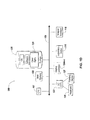
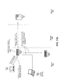
- a server 106 includes an application delivery system 290 for delivering a computing environment or an application and/or data file to one or more clients 102.
- a client 102 is in communication with a server 106 via network 104 and appliance 200.
- the client 102 may reside in a remote office of a company, e.g., a branch office, and the server 106 may reside at a corporate data center.
- the client 102 has a client agent 120, and a computing environment 215.
- the computing environment 215 may execute or operate an application that accesses, processes or uses a data file.
- the computing environment 215, application and/or data file may be delivered via the appliance 200 and/or the server 106.
- a first set of one or more servers 106 may execute the application delivery system 290, and a different server 106n may store or provide the application and data file.
- each of the application delivery system 290, the application, and data file may reside or be located on different servers.
- any portion of the application delivery system 290 may reside, execute or be stored on or distributed to the appliance 200, or a plurality of appliances.
- the client 102 may include a computing environment 215 for executing an application that uses or processes a data file.
- the client 102 via networks 104, 104' and appliance 200 may request an application and data file from the server 106.
- the appliance 200 may forward a request from the client 102 to the server 106.
- the client 102 may not have the application and data file stored or accessible locally.
- the application delivery system 290 and/or server 106 may deliver the application and data file to the client 102.
- the server 106 may transmit the application as an application stream to operate in computing environment 215 on client 102.
- the application delivery system 290 comprises any portion of the Citrix Access SuiteTM by Citrix Systems, Inc., such as the MetaFrame or Citrix Presentation ServerTM and/or any of the Microsoft® Windows Terminal Services manufactured by the Microsoft Corporation.
- the application delivery system 290 may deliver one or more applications to clients 102 or users via a remote-display protocol or otherwise via remote-based or server-based computing.
- the application delivery system 290 may deliver one or more applications to clients or users via steaming of the application.
- the application delivery system 290 includes a policy engine 295 for controlling and managing the access to applications, selection of application execution methods and the delivery of applications.
- the policy engine 295 determines the one or more applications a user or client 102 may access.
- the policy engine 295 determines how the application should be delivered to the user or client 102, e.g., the method of execution.
- the application delivery system 290 provides a plurality of delivery techniques from which to select a method of application execution, such as a server-based computing, streaming or delivering the application locally to the client 120 for local execution.
- a client 102 requests execution of an application program and the application delivery system 290 comprising a server 106 selects a method of executing the application program.
- the server 106 receives credentials from the client 102.
- the server 106 receives a request for an enumeration of available applications from the client 102.
- the application delivery system 290 enumerates a plurality of application programs available to the client 102.
- the application delivery system 290 receives a request to execute an enumerated application.
- the application delivery system 290 selects one of a predetermined number of methods for executing the enumerated application, for example, responsive to a policy of a policy engine.
- the application delivery system 290 may select a method of execution of the application enabling the client 102 to receive application-output data generated by execution of the application program on a server 106.
- the application delivery system 290 may select a method of execution of the application enabling the client or local machine 102 to execute the application program locally after retrieving a plurality of application files comprising the application.
- the application delivery system 290 may select a method of execution of the application to stream the application via the network 104 to the client 102.
- a client 102 may execute, operate or otherwise provide an application, which can be any type and/or form of software, program, or executable instructions such as any type and/or form of web browser, web-based client, client-server application, a thin-client computing client, an ActiveX control, or a Java applet, or any other type and/or form of executable instructions capable of executing on client 102.
- the application may be a server-based or a remote-based application executed on behalf of the client 102 on a server 106.
- the server 106 may display output to the client 102 using any thin-client or remote-display protocol, such as the Independent Computing Architecture (ICA) protocol manufactured by Citrix Systems, Inc. of Ft.
- ICA Independent Computing Architecture
- the application can use any type of protocol and it can be, for example, an HTTP client, an FTP client, an Oscar client, or a Telnet client.
- the application comprises any type of software related to VoIP communications, such as a soft IP telephone.
- the application comprises any application related to real-time data communications, such as applications for streaming video and/or audio.
- the appliance 200 includes or is under the control of an operating system.
- the operating system of the appliance 200 may be any type and/or form of Unix operating system although the invention is not so limited.
- the appliance 200 can be running any operating system such as any of the versions of the Microsoft® Windows operating systems, the different releases of the Unix and Linux operating systems, any version of the Mac OS® for Macintosh computers, any embedded operating system, any network operating system, any real-time operating system, any open source operating system, any proprietary operating system, any operating systems for mobile computing devices or network devices, or any other operating system capable of running on the appliance 200 and performing the operations described herein.
- the operating system of appliance 200 allocates, manages, or otherwise segregates the available system memory into what is referred to as kernel or system space, and user or application space.
- the kernel space is typically reserved for running the kernel, including any device drivers, kernel extensions or other kernel related software.
- the kernel is the core of the operating system, and provides access, control, and management of resources and hardware-related elements of the appliance 200.
- the kernel space also includes a number of network services or processes working in conjunction with the network optimization engine 250, or any portion thereof. Additionally, the embodiment of the kernel will depend on the embodiment of the operating system installed, configured, or otherwise used by the device 200.
- the appliance 200 has one or more network ports 266 for transmitting and receiving data over a network 104.
- the network port 266 provides a physical and/or logical interface between the computing device and a network 104 or another device 100 for transmitting and receiving network communications.
- the type and form of network port 266 depends on the type and form of network and type of medium for connecting to the network.
- any software of, provisioned for or used by the network port 266 and network stack 267 may run in either kernel space or user space.
- the appliance 200 has one network stack 267, such as a TCP/IP based stack, for communicating on a network 105, such with the client 102 and/or the server 106.
- the network stack 267 is used to communicate with a first network, such as network 104, and also with a second network 104'.
- the appliance 200 has two or more network stacks, such as first network stack 267A and a second network stack 267N.
- the first network stack 267A may be used in conjunction with a first port 266A to communicate on a first network 104.
- the second network stack 267N may be used in conjunction with a second port 266N to communicate on a second network 104'.
- the network stack(s) 267 has one or more buffers for queuing one or more network packets for transmission by the appliance 200.
- the network stack 267 may include one or more network drivers supporting the one or more layers, such as a TCP driver or a network layer driver.
- the network drivers may be included as part of the operating system of the computing device 100 or as part of any network interface cards or other network access components of the computing device 100.
- any of the network drivers of the network stack 267 may be customized, modified or adapted to provide a custom or modified portion of the network stack 267 in support of any of the techniques described herein.
- the appliance 200 provides for or maintains a transport layer connection between a client 102 and server 106 using a single network stack 267.
- the appliance 200 effectively terminates the transport layer connection by changing, managing or controlling the behavior of the transport control protocol connection between the client and the server.
- the appliance 200 may use a single network stack 267.
- the appliance 200 terminates a first transport layer connection, such as a TCP connection of a client 102, and establishes a second transport layer connection to a server 106 for use by or on behalf of the client 102, e.g., the second transport layer connection is terminated at the appliance 200 and the server 106.
- the first and second transport layer connections may be established via a single network stack 267.
- the packet engine 240 intercepts or otherwise receives packets at the transport layer, such as intercepting packets as the TCP layer in a TCP/IP embodiment.
- the packet engine 240 operates at any session or application layer above layer 4.
- the packet engine 240 intercepts or otherwise receives network packets above the transport layer protocol layer, such as the payload of a TCP packet in a TCP embodiment.
- any of the logic, functions, or operations of the encryption engine 234, cache manager 232, policy engine 236 and multi-protocol compression logic 238 may be performed at the granularity of time intervals provided via the packet processing timer, for example, at a time interval of less than or equal to 10ms.
- the cache manager 232 may perform expiration of any cached objects responsive to the integrated packet engine 240 and/or the packet processing timer 242.
- the expiry or invalidation time of a cached object can be set to the same order of granularity as the time interval of the packet processing timer, such as at every 10 ms.
- the policy engine 295' includes any logic, function or operations for providing and applying one or more policies or rules to the function, operation or configuration of any portion of the appliance 200.
- the policy engine 295' may include, for example, an intelligent statistical engine or other programmable application(s).
- the policy engine 295 provides a configuration mechanism to allow a user to identify, specify, define or configure a policy for the network optimization engine 250, or any portion thereof.
- the policy engine 295 may provide policies for what data to cache, when to cache the data, for whom to cache the data, when to expire an object in cache or refresh the cache.
- the compression engine 238 includes any logic, business rules, function or operations for compressing one or more protocols of a network packet, such as any of the protocols used by the network stack 267 of the appliance 200.
- the compression engine 238 may also be referred to as a multi-protocol compression engine 238 in that it may be designed, constructed or capable of compressing a plurality of protocols.
- the compression engine 238 applies context insensitive compression, which is compression applied to data without knowledge of the type of data.
- the compression engine 238 applies context-sensitive compression.
- the compression engine 238 utilizes knowledge of the data type to select a specific compression algorithm from a suite of suitable algorithms. In some embodiments, knowledge of the specific protocol is used to perform context-sensitive compression.
- the LAN/WAN detector 238 includes any logic, business rules, function or operations for automatically detecting a slow side connection (e.g., a wide area network (WAN) connection such as an Intranet) and associated port 267, and a fast side connection (e.g., a local area network (LAN) connection) and an associated port 267.
- a slow side connection e.g., a wide area network (WAN) connection such as an Intranet
- a fast side connection e.g., a local area network (LAN) connection
- the LAN/WAN detector 238 monitors network traffic on the network ports 267 of the appliance 200 to detect a synchronization packet, sometimes referred to as a "tagged" network packet.
- the synchronization packet identifies a type or speed of the network traffic. In one embodiment, the synchronization packet identifies a WAN speed or WAN type connection.
- the LAN/WAN detector 238 also identifies receipt of an acknowledgement packet to a tagged synchronization packet and on which port it is received.
- the appliance 200 then configures itself to operate the identified port on which the tagged synchronization packet arrived so that the speed on that port is set to be the speed associated with the network connected to that port.
- the other port is then set to the speed associated with the network connected to that port.
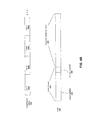
- the client 102 When an end node, such as the client 102, opens a new TCP connection with another end node, such as the server 106, the client 102 sends a TCP packet with a synchronization (SYN) header bit set, or a SYN packet, to the server 106.
- SYN synchronization
- client 102 opens a transport layer connection to server 106.
- the appliance 200 inserts, attaches or otherwise provides a characteristic TCP header option to the packet, which announces its presence. If the packet passes through a second appliance, in this example appliance 200' the second appliance notes the header option on the SYN packet.
- the server 106 responds to the SYN packet with a synchronization acknowledgment (SYN-ACK) packet.
- SYN-ACK synchronization acknowledgment
- the LAN/WAN detector 238 detects fast and slow sides of a network using a SYN-ACK packet.
- the appliance 200 via the LAN/WAN detector 238 determines whether the SYN-ACK packet is tagged with an acknowledgement (ACK). If it is tagged, the appliance 200 identifies or configures the port receiving the tagged SYN packet (SYN-ACK) as the "slow" side. In one embodiment, the appliance 200 optionally removes the ACK tag from the packet before copying the packet to the other port. If the LAN/WAN detector 238 determines that the packet is not tagged, the appliance 200 identifies or configures the port receiving the untagged packet as the "fast" side.
- ACK acknowledgement
- the appliance 200 optionally removes the ACK tag from the packet before copying the packet to the other port. If the LAN/WAN detector 238 determines that the packet is not tagged, the appliance 200 identifies or configures the port receiving the untagged packet as the "fast" side.
- the LAN/WAN detector 238 can be used for applying any type of function, logic or operation of the appliance 200 to a port, connection or flow of network traffic.
- automated assignment of ports can occur whenever a device performs different functions on different ports, where the assignment of a port to a task can be made during the unit's operation, and/or the nature of the network segment on each port is discoverable by the appliance 200.
- the flow control module 200 is configured with predetermined data relating to bottleneck bandwidth. In another embodiment, the flow control module 220 may be configured to detect the bottleneck bandwidth or data associated therewith.
- a receiver-side flow control module 220 may control the data transmission rate.
- the receiver-side flow control module controls 220 the sender-side flow control module, e.g., 220, data transmission rate by forwarding transmission rate limits to the sender-side flow control module 220.
- the receiver-side flow control module 220 piggybacks these transmission rate limits on acknowledgement (ACK) packets (or signals) sent to the sender, e.g., client 102, by the receiver, e.g., server 106.
- ACK acknowledgement
- the client 102 transmits a packet, which is received by the appliance 200.
- the appliance 200 receives the packet, which is transmitted from the client 102 to a recipient via the VPN appliance 205, the appliance 200 retains a copy of the packet and forwards the packet downstream to the VPN appliance 205.
- the appliance 200 then generates an acknowledgement packet (ACK) and sends the ACK packet back to the client 102 or sending endpoint.
- ACK acknowledgement packet
- This ACK a pre-acknowledgment, causes the sender 102 to believe that the packet has been delivered successfully, freeing the sender's resources for subsequent processing.
- the appliance 200 retains the copy of the packet data in the event that a retransmission of the packet is required, so that the sender 102 does not have to handle retransmissions of the data. This early generation of acknowledgements may be called "preacking.”
- the appliance 200 retransmits the packet to the sender.
- the appliance 200 may determine whether retransmission is required as a sender would in a traditional system, for example, determining that a packet is lost if an acknowledgement has not been received for the packet after a predetermined amount of time. To this end, the appliance 200 monitors acknowledgements generated by the receiving endpoint, e.g., server 106 (or any other downstream network entity) so that it can determine whether the packet has been successfully delivered or needs to be retransmitted. If the appliance 200 determines that the packet has been successfully delivered, the appliance 200 is free to discard the saved packet data. The appliance 200 may also inhibit forwarding acknowledgements for packets that have already been received by the sending endpoint.
- the overflow control mechanism in the appliance 200 can require that a minimum amount of space be available before sending a nonzero window advertisement to the sender.
- the appliance 200 waits until there is a minimum of a predetermined number of packets, such as four packets, of space available before sending a nonzero window packet, such as a packet indicating a window size of four packets. This may reduce the overhead by approximately a factor of four, since only two ACK packets are sent for each group of four data packets, instead of eight ACK packets for four data packets.
- TCP delayed ACK Another technique the appliance 200 or flow controller 220 may use for overflow control is the TCP delayed ACK mechanism, which skips ACKs to reduce network traffic.
- the TCP delayed ACKs automatically delay the sending of an ACK, either until two packets are received or until a fixed timeout has occurred. This mechanism alone can result in cutting the overhead in half; moreover, by increasing the numbers of packets above two, additional overhead reduction is realized. But merely delaying the ACK itself may be insufficient to control overflow, and the appliance 200 may also use the advertised window mechanism on the ACKs to control the sender. When doing this, the appliance 200 in one embodiment avoids triggering the timeout mechanism of the sender by delaying the ACK too long.
- the flow controller 220 may use a window virtualization technique to control the rate of flow or bandwidth utilization of a network connection.
- a send window for transport layer protocols such as TCP.
- the send window is similar to the receive window, in that it consumes buffer space (though on the sender).
- the sender's send window consists of all data sent by the application that has not been acknowledged by the receiver. This data must be retained in memory in case retransmission is required. Since memory is a shared resource, some TCP stack implementations limit the size of this data.
- This window size is known as the socket buffer size in some TCP implementations.
- the flow control module 220 is configured to provide access to increased window (or buffer) sizes. This configuration may also be referenced to as window virtualization.
- the TCP header may include a bit string corresponding to a window scale.
- window may be referenced in a context of send, receive, or both.
- the appliances 200 via a flow control module 220 provide window (or buffer) to allow increasing data buffering capabilities within a session despite having end nodes with small buffer sizes, e.g., typically 16 k bytes.
- RFC 1323 requires window scaling for any buffer sizes greater than 64 k bytes, which must be set at the time of session initialization (SYN, SYN-ACK signals).
- the window scaling corresponds to the lowest common denominator in the data path, often an end node with small buffer size.
- This window scale often is a scale of 0 or 1, which corresponds to a buffer size of up to 64 k or 128 k bytes. Note that because the window size is defined as the window field in each packet shifted over by the window scale, the window scale establishes an upper limit for the buffer, but does not guarantee the buffer is actually that large.
- Each packet indicates the current available buffer space at the receiver in the window field.
- the flow control module 220 stores the windows scale of the source node 102 (which is the previous node) or stores a 0 for window scale if the scale of the previous node is missing.
- the first flow control module 220 also modifies the scale, e.g., increases the scale to 4 from 0 or 1, in the SYN-FCM signal.
- the second flow control module 220 When the second flow control module 220 receives the SYN signal, it stores the increased scale from the first flow control signal and resets the scale in the SYN signal back to the source node 103 scale value for transmission to the destination node 106.
- the second flow controller 220 receives the SYN-ACK signal from the destination node 106, it stores the scale from the destination node 106 scale, e.g., 0 or 1, and modifies it to an increased scale that is sent with the SYN-ACK-FCM signal.
- the first flow control node 220 receives and notes the received window scale and revises the windows scale sent back to the source node 102 back down to the original scale, e.g., 0 or 1. Based on the above window shift conversation during connection establishment, the window field in every subsequent packet, e.g., TCP packet, of the session must be shifted according to the window shift conversion.
- the window scale expresses buffer sizes of over 64 k and may not be required for window virtualization.
- shifts for window scale may be used to express increased buffer capacity in each flow control module 220.
- This increase in buffer capacity in may be referenced as window (or buffer) virtualization.
- the increase in buffer size allows greater packet throughput from and to the respective end nodes 102 and 106.
- buffer sizes in TCP are typically expressed in terms of bytes, but for ease of discussion "packets" may be used in the description herein as it relates to virtualization.
- a window (or buffer) virtualization performed by the flow controller 220 is described.
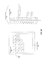
- the source node 102 and the destination node 106 are configured similar to conventional end nodes having a limited buffer capacity of 16 k bytes, which equals approximately 10 packets of data.
- an end node 102, 106 must wait until the packet is transmitted and confirmation is received before a next group of packets can be transmitted.
- the first flow control module 220 when the source node 103 transmits its data packets, the first flow control module 220 receives the packets, stores it in its larger capacity buffer, e.g., 512 packet capacity, and immediately sends back an acknowledgement signal indicating receipt of the packets ("REC-ACK") back to the source node 102.
- the source node 102 can then "flush" its current buffer, load the buffer with 10 new data packets, and transmit those onto the first flow control module 220.
- the first flow control module 220 transmits a REC-ACK signal back to the source node 102 and the source node 102 flushes its buffer and loads it with 10 more new packets for transmission.
- the first flow control module 220 receives the data packets from the source nodes, it loads up its buffer accordingly. When it is ready the first flow control module 220 can begin transmitting the data packets to the second flow control module 230, which also has an increased buffer size, for example, to receive 512 packets.
- the second flow control module 220' receives the data packets and begins to transmit 10 packets at a time to the destination node 106. Each REC-ACK received at the second flow control node 220 from the destination node 106 results in 10 more packets being transmitted to the destination node 106 until all the data packets are transferred.
- the present invention is able to increase data transmission throughput between the source node (sender) 102 and the destination node (receiver) 106 by taking advantage of the larger buffer in the flow control modules 220, 220' between the devices.
- a sender or source node 102 is allowed to transmit more data than is possible without the preacks, thus affecting a larger window size.
- this technique is effective when the flow control module 220, 220' is located "near" a node (e.g., source node 102 or destination node 106) that lacks large windows.
- recongestion Another technique or algorithm of the flow controller 220 is referred to as recongestion.
- the standard TCP congestion avoidance algorithms are known to perform poorly in the face of certain network conditions, including: large RTTs (round trip times), high packet loss rates, and others.
- the appliance 200 detects a congestion condition such as long round trip times or high packet loss, the appliance 200 intervenes, substituting an alternate congestion avoidance algorithm that better suits the particular network condition.
- the recongestion algorithm uses preacks to effectively terminate the connection between the sender and the receiver.
- the appliance 200 then resends the packets from itself to the receiver, using a different congestion avoidance algorithm.
- Recongestion algorithms may be dependent on the characteristics of the TCP connection.
- the appliance 200 monitors each TCP connection, characterizing it with respect to the different dimensions, selecting a recongestion algorithm that is appropriate for the current characterization.
- a recongestion algorithm upon detecting a TCP connection that is limited by round trip times (RTT), a recongestion algorithm is applied which behaves as multiple TCP connections. Each TCP connection operates within its own performance limit but the aggregate bandwidth achieves a higher performance level.
- One parameter in this mechanism is the number of parallel connections that are applied (N). Too large a value ofN and the connection bundle achieves more than its fair share of bandwidth. Too small a value of N and the connection bundle achieves less than its fair share of bandwidth.
- One method of establishing "N" relies on the appliance 200 monitoring the packet loss rate, RTT, and packet size of the actual connection. These numbers are plugged into a TCP response curve formula to provide an upper limit on the performance of a single TCP connection in the present configuration.
- Another method of establishing "N” is to utilize a parallel flow control algorithm such as the TCP "Vegas” algorithm or the TCP "Stabilized Vegas” algorithm.
- the network information associated with the connections in the connection bundle e.g., RTT, loss rate, average packet size, etc.
- the results of this algorithm are in turn distributed among the connections of the bundle controlling their number (i.e., N).
- each connection within the bundle continues using the standard TCP congestion avoidance algorithm.
- the individual connections within a parallel bundle are virtualized, i.e., actual individual TCP connections are not established. Instead the congestion avoidance algorithm is modified to behave as though there were N parallel connections. This method has the advantage of appearing to transiting network nodes as a single connection. Thus the QOS, security and other monitoring methods of these nodes are unaffected by the recongestion algorithm.
- the individual connections within a parallel bundle are real, i.e., a separate. TCP connection is established for each of the parallel connections within a bundle. The congestion avoidance algorithm for each TCP connection need not be modified.
- the appliance 200 uses a retransmit and timeout algorithm is avoid premature RTOs.
- the appliance 200 or flow controller 220 maintains a count of retransmissions is maintained on a per-packet basis. Each time that a packet is retransmitted, the count is incremented by one and the appliance 200 continues to transmit packets. In some embodiments, only if a packet has been retransmitted a predetermined number of times is an RTO declared.
- the sender As the sender transmits data packets, the sender maintains a data structure of acknowledged instances of data packet transmissions. Each instance of a data packet transmission is referenced by its sequence number and transmit number. By maintaining a transmit number for each packet, the sender retains the ordering of the transmission of data packets. When the sender receives an ACK or a SACK, the sender determines the highest transmit number associated with packets that the receiver indicated has arrived (in the received acknowledgement). Any outstanding unacknowledged packets with lower transmit numbers are presumed lost.
- the sender includes an identifier with a transmitted data packet, and the receiver returns that identifier or a function thereof with the acknowledgement.
- the identifier may be a timestamp (e.g., a TCP timestamp as described in RFC 1323), a sequential number, or any other information that can be used to resolve between two or more instances of a packet's transmission.
- a timestamp e.g., a TCP timestamp as described in RFC 1323
- each packet is tagged with up to 32-bits of unique information.
- the receiver echoes this unique information back to the sender with the acknowledgement.
- the sender ensures that the originally sent packet and its retransmitted version or versions contain different values for the timestamp option, allowing it to unambiguously eliminate the ACK ambiguity.
- the sender may maintain this unique information, for example, in the data structure in which it stores the status of sent data packets.
- This technique is advantageous because it complies with industry standards and is thus likely to encounter little or no interoperability issues. However, this technique may require ten bytes of TCP header space in some implementations, reducing the effective throughput rate on the network and reducing space available for other TCP options.
- another field in the packet such as the IP ID field
- the sender arranges for the ID field values of the original and the retransmitted version or versions of the packet to have different ID fields in the IP header.
- the receiver sets the ID field of the ACK packet to a function of the ID field of the packet that triggers the ACK.
- This method is advantageous, as it requires no additional data to be sent, preserving the efficiency of the network and TCP header space.
- the function chosen should provide a high degree of likelihood of providing disambiguation.
- the sender selects IP ID values with the most significant bit set to 0. When the receiver responds, the IP ID value is set to the same IP ID value with the most significant bit set to a one.
- the transmit numbers associated with non-ambiguous acknowledgements are used to disambiguate an ambiguous acknowledgement.
- This technique is based on the principle that acknowledgements for two packets will tend to be received closer in time as the packets are transmitted closer in time. Packets that are not retransmitted will not result in ambiguity, as the acknowledgements received for such packets can be readily associated with a transmit number. Therefore, these known transmit numbers are compared to the possible transmit numbers for an ambiguous acknowledgement received near in time to the known acknowledgement. The sender compares the transmit numbers of the ambiguous acknowledgement against the last known received transmit number, selecting the one closest to the known received transmit number. For example, if an acknowledgement for data packet 1 is received and the last received acknowledgement was for data packet 5, the sender resolves the ambiguity by assuming that the third instance of data packet 1 caused the acknowledgement.
- the receiver returns a TCP Selective Acknowledgment option, referred to as SACK packet to the sender.
- the communication is bi-directional, although only one direction of communication is discussed here for simplicity.
- the receiver maintains a list, or other suitable data structure, that contains a group of ranges of sequence numbers for data packets that the receiver has actually received. In some embodiments, the list is sorted by sequence number in an ascending or descending order.
- the receiver also maintains a left-off pointer, which comprises a reference into the list and indicates the left-off point from the previously generated SACK packet.
- the receiver Upon reception of a data packet, the receiver generates and transmits a SACK packet back to the sender.
- the SACK packet includes a number of fields, each of which can hold a range of sequence numbers to indicate a set of received data packets.
- the receiver fills this first field of the SACK packet with a range of sequence numbers that includes the landing packet that triggered the SACK packet.
- the remaining available SACK fields are filled with ranges of sequence numbers from the list of received packets. As there are more ranges in the list than can be loaded into the SACK packet, the receiver uses the left-off pointer to determine which ranges are loaded into the SACK packet.
- the receiver inserts the SACK ranges consecutively from the sorted list, starting from the range referenced by the pointer and continuing down the list until the available SACK range space in the TCP header of the SACK packet is consumed.
- the receiver wraps around to the start of the list if it reaches the end. In some embodiments, two or three additional SACK ranges can be added to the SACK range information.
- the receiver sends the acknowledgement back to the sender.
- the receiver advances the left-off pointer by one or more SACK range entries in the list. If the receiver inserts four SACK ranges, for example, the left-off pointer may be advanced two SACK ranges in the list. When the advanced left-off pointer reaches at the end of the list, the pointer is reset to the start of the list, effectively wrapping around the list of known received ranges. Wrapping around the list enables the system to perform well, even in the presence of large losses of SACK packets, since the SACK information that is not communicated due to a lost SACK packet will eventually be communicated once the list is wrapped around.
- a SACK packet may communicate several details about the condition of the receiver.
- the SACK packet indicates that, upon generation of the SACK packet, the receiver had just received a data packet that is within the first field of the SACK information.
- the second and subsequent fields of the SACK information indicate that the receiver has received the data packets within those ranges.
- the SACK information also implies that the receiver had not, at the time of the SACK packet's generation, received any of the data packets that fall between the second and subsequent fields of the SACK information.
- the ranges between the second and subsequent ranges in the SACK information are "holes" in the received data, the data therein known not to have been delivered.
- the receiver may indicate to the sender a range of data packets that have not yet been received by the receiver.
- the appliance 200 or flow controller 220 applies a technique referred to as transaction boundary detection.
- the technique pertains to ping-pong behaved connections.
- ping-pong behavior is when one communicant - a sender- sends data and then waits for a response from the other communicant - the receiver. Examples of ping-pong behavior include remote procedure call, HTTP and others.
- the algorithms described above use retransmission timeout (RTO) to recover from the dropping of the last packet or packets associated with the transaction. Since the TCP RTO mechanism is extremely coarse in some embodiments, for example requiring a minimum one second value in all cases), poor application behavior may be seen in these situations.
- RTO retransmission timeout
- One method of detecting a transaction boundary is time based. If the sender has been sending data and ceases, then after a period of time the sender or flow control module 200 declares a transaction boundary. This may be combined with other techniques. For example, the setting of the PSH (TCP Push) bit by the sender in the TCP header may indicate a transaction boundary. Accordingly, combining the time-based approach with these additional heuristics can provide for more accurate detection of a transaction boundary. In another technique, if the sender or flow control module 220 understands the application protocol, it can parse the protocol data stream and directly determine transaction boundaries. In some embodiment, this last behavior can be used independent of any time-based mechanism.
- PSH TCP Push
- the sender or flow control module 220 transmits additional data packets to the receiver to cause acknowledgements therefrom.
- the additional data packets should therefore be such that the receiver will at least generate an ACK or SACK in response to receiving the data packet.
- the last packet or packets of the transaction are simply retransmitted. This has the added benefit of retransmitting needed data if the last packet or packets had been dropped, as compared to merely sending dummy data packets.
- fractions of the last packet or packets are sent, allowing the sender to disambiguate the arrival of these packets from their original packets. This allows the receiver to avoid falsely confusing any reordering adaptation algorithms.
- any of a number of well-known forward error correction techniques can be used to generate additional data for the inserted packets, allowing for the reconstruction of dropped or otherwise missing data at the receiver.
- the packet size may lead to lower transmission rates, as media-induced errors cause an entire packet to be dropped (i.e., media-induced errors beyond the capability of the standard error correcting code for that media), increasing the packet loss rate.
- a sufficiently large increase in the packet loss rate will actually negate any performance benefit of increasing packet size.
- the optimal packet size may vary across the transmission path, depending on the nature of each link.
- the flow controller 220 monitors characteristics of the link and repacketizes according to determined link characteristics. In one embodiment, an appliance 200 or flow controller 220 repacketizes packets with sequential data into a smaller number of larger packets. In another embodiment, an appliance 200 or flow controller 220 repacketizes packets by breaking part a sequence of large packets into a larger number of smaller packets. In other embodiments, an appliance 200 or flow controller 220 monitors the link characteristics and adjusts the packet sizes through recombination to improve throughput.
- the flow controller 220 may include a QoS Engine 236, also referred to as a QoS controller.
- the appliance 200 and/or network optimization engine 250 includes the QoS engine 236, for example, separately but in communication with the flow controller 220.
- the QoS Engine 236 includes any logic, business rules, function or operations for performing one or more Quality of Service (QoS) techniques improving the performance, operation or quality of service of any of the network connections.
- QoS engine 236 includes network traffic control and management mechanisms that provide different priorities to different users, applications, data flows or connections.
- the QoS engine 236 controls, maintains, or assures a certain level of performance to a user, application, data flow or connection. In one embodiment, the QoS engine 236 controls, maintains or assures a certain portion of bandwidth or network capacity for a user, application, data flow or connection. In some embodiments, the QoS engine 236 monitors the achieved level of performance or the quality of service corresponding to a user, application, data flow or connection, for example, the data rate and delay. In response to monitoring, the QoS engine 236 dynamically controls or adjusts scheduling priorities of network packets to achieve the desired level of performance or quality of service.
- the QoS engine 236 prioritizes, schedules and transmits network packets according to one or more classes or levels of services.
- the class or level service may include: 1) best efforts, 2) controlled load, 3) guaranteed or 4) qualitative.
- the appliance 200 makes reasonable effort to deliver packets (a standard service level).
- the appliance 200 or QoS engine 236 approximates the standard packet error loss of the transmission medium or approximates the behavior of best-effort service in lightly loaded network conditions.
- the appliance 200 or QoS engine 236 guarantees the ability to transmit data at a determined rate for the duration of the connection.
- the appliance 200 or QoS engine 236 determines the class of service or priortization based on any logic or configuration of the QoS engine 236 or based on business rules or policies. For example, in one embodiment, the QoS engine 236 prioritizes, schedules and transmits network packets according to one or more policies as specified by the policy engine 295, 295'.
- the protocol accelerator 234 includes any logic, business rules, function or operations for optimizing, accelerating, or otherwise improving the performance, operation or quality of service of one or more protocols. In one embodiment, the protocol accelerator 234 accelerates any application layer protocol or protocols at layers 5-7 of the network stack. In other embodiments, the protocol accelerator 234 accelerates a transport layer or a layer 4 protocol. In one embodiment, the protocol accelerator 234 accelerates layer 2 or layer 3 protocols. In some embodiments, the protocol accelerator 234 is configured, constructed or designed to optimize or accelerate each of one or more protocols according to the type of data, characteristics and/or behavior of the protocol. In another embodiment, the protocol accelerator 234 is configured, constructed or designed to improve a user experience, response times, network or computer load, and/or network or bandwidth utilization with respect to a protocol.
- the protocol accelerator 234 is configured, constructed or designed to minimize the effect of WAN latency on file system access. In some embodiments, the protocol accelerator 234 optimizes or accelerates the use of the CIFS (Common Internet File System) protocol to improve file system access times or access times to data and files. In some embodiments, the protocol accelerator 234 optimizes or accelerates the use of the NFS (Network File System) protocol. In another embodiment, the protocol accelerator 234 optimizes or accelerates the use of the File Transfer protocol (FTP).
- CIFS Common Internet File System
- NFS Network File System
- FTP File Transfer protocol
- the protocol accelerator 234 is configured, constructed or designed to optimize or accelerate a protocol carrying as a payload or using any type and form of markup language. In other embodiments, the protocol accelerator 234 is configured, constructed or designed to optimize or accelerate a HyperText Transfer Protocol (HTTP). In another embodiment, the protocol accelerator 234 is configured, constructed or designed to optimize or accelerate a protocol carrying as a payload or otherwise using XML (eXtensible Markup Language).
- HTTP HyperText Transfer Protocol
- XML eXtensible Markup Language
- the appliance 200 and/or network optimization engine 250 is transparent to any data flowing across a network connection or link, such as a WAN link.
- the appliance 200 and/or network optimization engine 250 operates in such a manner that the data flow across the WAN is recognizable by any network monitoring, QOS management or network analysis tools.
- the appliance 200 and/or network optimization engine 250 does not create any tunnels or streams for transmitting data that may hide, obscure or otherwise make the network traffic not transparent.
- the appliance 200 operates transparently in that the appliance does not change any of the source and/or destination address information or port information of a network packet, such as internet protocol addresses or port numbers.
- the appliance 200 is deployed inline with a WAN link of a router. In this way, all traffic from the WAN passes through the appliance before arriving at a destination of a LAN.
- the appliance 200 is deployed as a proxy device between a client and a server.
- the appliance 200 allows clients to make indirect connections to a resource on a network.
- a client connects to a resource via the appliance 200, and the appliance provides the resource either by connecting to the resource, a different resource, or by serving the resource from a cache.
- the appliance may alter the client's request or the server's response for various purposes, such as for any of the optimization techniques discussed herein.
- the client 102 send requests addressed to the proxy.
- the proxy responds to the client in place of or acting as a server 106.
- the appliance 200 behaves as a transparent proxy, by intercepting and forwarding requests and responses transparently to a client and/or server. Without client-side configuration, the appliance 200 may redirect client requests to different servers or networks. In some embodiments, the appliance 200 may perform any type and form of network address translation, referred to as NAT, on any network traffic traversing the appliance.
- NAT network address translation
- the appliance 200 is deployed in a virtual in-line mode configuration.
- a router or a network device with routing or switching functionality is configured to forward, reroute or otherwise provide network packets destined to a network to the appliance 200.
- the appliance 200 then performs any desired processing on the network packets, such as any of the WAN optimization techniques discussed herein.
- the appliance 200 forwards the processed network packet to the router to transmit to the destination on the network.
- the appliance 200 can be coupled to the router in parallel but still operate as it if the appliance 200 were inline.
- This deployment mode also provides transparency in that the source and destination addresses and port information are preserved as the packet is processed and transmitted via the appliance through the network.
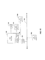
- the network optimization engine 250 is generally described above in conjunction with an appliance 200, the network optimization engine 250, or any portion thereof, may be deployed, distributed or otherwise operated on any end node, such as a client 102 and/or server 106. As such, a client or server may provide any of the systems and methods of the network optimization engine 250 described herein in conjunction with one or more appliances 200 or without an appliance 200.
- the network optimization engine 250' of the client 102 performs the techniques described herein to optimize, accelerate or otherwise improve the performance, operation or quality of service of network traffic communicated with the server 106.
- the network optimization engine 250" of the server 106 performs the techniques described herein to optimize, accelerate or otherwise improve the performance, operation or quality of service of network traffic communicated with the client 102.
- the network optimization engine 250' of the client 102 and the network optimization engine 250" of the server 106 perform the techniques described herein to optimize, accelerate or otherwise improve the performance, operation or quality of service of network traffic communicated between the client 102 and the server 106.
- the network optimization engine 250' of the client 102 performs the techniques described herein in conjunction with an appliance 200 to optimize, accelerate or otherwise improve the performance, operation or quality of service of network traffic communicated with the client 102.
- the network optimization engine 250" of the server 106 performs the techniques described herein in conjunction with an appliance 200 to optimize, accelerate or otherwise improve the performance, operation or quality of service of network traffic communicated with the server 106.
- a client deployed in the system or with an appliance 200 or 205 may include a client agent 120.
- the client agent 120 is used to facilitate communications with one or more appliances 200 or 205.
- any of the systems and methods of the appliance 200 or 205 described herein may be deployed, implemented or embodied in a client, such as via a client agent 120.
- the client agent 120 may include applications, programs, or agents providing additional functionality such as end point detection and authorization, virtual private network connectivity, and application streaming. Prior to discussing other embodiments of systems and methods of the appliance 200, embodiments of the client agent 120 will be described.
- one or more applications may communicate via the network stack 267 to a network 104.
- One of the applications such as a web browser, may also include a first program 322.
- the first program 322 may be used in some embodiments to install and/or execute the client agent 120, or any portion thereof.
- the client agent 120 includes an interception mechanism, or interceptor 350, for intercepting network communications from the network stack 267 from the one or more applications.
- the client has a network stack 267 including any type and form of software, hardware, or any combinations thereof, for providing connectivity to and communications with a network 104.
- the network stack 267 of the client 102 includes any of the network stack embodiments described above in conjunction with the appliance 200.
- the client agent 120, or any portion thereof, is designed and constructed to operate with or work in conjunction with the network stack 267 installed or otherwise provided by the operating system of the client 102.
- the network stack 267 of the client 102 or appliance 200 may include any type and form of interfaces for receiving, obtaining, providing or otherwise accessing any information and data related to network communications of the client 102.
- an interface to the network stack 267 includes an application programming interface (API).
- API application programming interface
- the interface may also have any function call, hooking or filtering mechanism, event or call back mechanism, or any type of interfacing technique.
- the network stack 267 via the interface may receive or provide any type and form of data structure, such as an object, related to functionality or operation of the network stack 267.
- the data structure may include information and data related to a network packet or one or more network packets.
- the data structure includes, references or identifies a portion of the network packet processed at a protocol layer of the network stack 267, such as a network packet of the transport layer.
- the data structure 325 is a kernel-level data structure, while in other embodiments, the data structure 325 is a user-mode data structure.
- a kernel-level data structure may have a data structure obtained or related to a portion of the network stack 267 operating in kernel-mode 302, or a network driver or other software running in kernel-mode 302, or any data structure obtained or received by a service, process, task, thread or other executable instructions running or operating in kernel-mode of the operating system.
- Each of the first portion 310a and second portion 310b of the network stack 267 may include any portion of the network stack 267, at any one or more network layers, in user-mode 303, kernel-mode, 302, or combinations thereof, or at any portion of a network layer or interface point to a network layer or any portion of or interface point to the user-mode 302 and kernel-mode 203.
- the interceptor 350 may include software, hardware, or any combination of software and hardware.
- the interceptor 350 intercepts or otherwise receives a network communication at any point in the network stack 267, and redirects or transmits the network communication to a destination desired, managed or controlled by the interceptor 350 or client agent 120.
- the interceptor 350 may intercept a network communication of a network stack 267 of a first network and transmit the network communication to the appliance 200 for transmission on a second network 104.
- the interceptor 350 includes or is a driver, such as a network driver constructed and designed to interface and work with the network stack 267.
- the client agent 120 and/or interceptor 350 operates at one or more layers of the network stack 267, such as at the transport layer.
- the interceptor 350 includes a filter driver, hooking mechanism, or any form and type of suitable network driver interface that interfaces to the transport layer of the network stack, such as via the transport driver interface (TDI).
- the interceptor 350 interfaces to a first protocol layer, such as the transport layer and another protocol layer, such as any layer above the transport protocol layer, for example, an application protocol layer.
- the interceptor 350 includes a driver complying with the Network Driver Interface Specification (NDIS), or a NDIS driver.
- the interceptor 350 may be a min-filter or a mini-port driver.
- the interceptor 350, or portion thereof operates in kernel-mode 202.
- the interceptor 350 operates in user-mode 203.
- a portion of the interceptor 350 operates in kernel-mode 202 while another portion of the interceptor 350 operates in user-mode 203.
- the client agent 120 operates in user-mode 203 but interfaces via the interceptor 350 to a kernel-mode driver, process, service, task or portion of the operating system, such as to obtain a kernel-level data structure 225.
- the interceptor 350 is a user-mode application or program, such as application.
- the interceptor 350 intercepts a Domain Name Service (DNS) request.
- DNS Domain Name Service
- the client agent 120 and/or interceptor 350 resolves the DNS request.
- the interceptor transmits the intercepted DNS request to the appliance 200 for DNS resolution.
- the appliance 200 resolves the DNS request and communicates the DNS response to the client agent 120.
- the appliance 200 resolves the DNS request via another appliance 200' or a DNS server 106.
- the client agent 120 and/or interceptor 350 may operate at or interface with a protocol layer in a manner transparent to any other protocol layer of the network stack 267.
- the interceptor 350 operates or interfaces with the transport layer of the network stack 267 transparently to any protocol layer below the transport layer, such as the network layer, and any protocol layer above the transport layer, such as the session, presentation or application layer protocols. This allows the other protocol layers of the network stack 267 to operate as desired and without modification for using the interceptor 350.
- the client agent 120 and/or interceptor 350 interfaces with or operates at the level of the transport layer to secure, optimize, accelerate, route or load-balance any communications provided via any protocol carried by the transport layer, such as any application layer protocol over TCP/IP.
- the client agent 120 and/or interceptor 350 may operate at or interface with the network stack 267 in a manner transparent to any application, a user of the client 102, the client 102 and/or any other computing device 100, such as a server or appliance 200, 206, in communications with the client 102.
- the client agent 120, or any portion thereof may be installed and/or executed on the client 102 in a manner without modification of an application.
- the client agent 120, or any portion thereof is installed and/or executed in a manner transparent to any network configuration of the client 102, appliance 200, 205 or server 106.
- the client agent 120 is installed and/or executed with modification to any network configuration of the client 102, appliance 200, 205 or server 106.
- the user of the client 102 or a computing device in communications with the client 102 are not aware of the existence, execution or operation of the client agent 12, or any portion thereof.
- the client agent 120 and/or interceptor 350 is installed, executed, and/or operated transparently to an application, user of the client 102, the client 102, another computing device, such as a server or appliance 200, 2005, or any of the protocol layers above and/or below the protocol layer interfaced to by the interceptor 350.
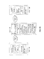
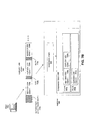
- the client agent 120 includes a streaming client 306, a collection agent 304, SSL VPN agent 308, a network optimization engine 250, and/or acceleration program 302.
- the client agent 120 is an Independent Computing Architecture (ICA) client, or any portion thereof, developed by Citrix Systems, Inc. of Fort Lauderdale, Florida, and is also referred to as an ICA client.
- the client agent 120 has an application streaming client 306 for streaming an application from a server 106 to a client 102.
- the client agent 120 includes a collection agent 304 for performing end-point detection/scanning and collecting end-point information for the appliance 200 and/or server 106.
- the client agent 120 has one or more network accelerating or optimizing programs or agents, such as a network optimization engine 250 and an acceleration program 302.
- the acceleration program 302 accelerates communications between client 102 and server 106 via appliance 205'.
- the network optimization engine 250 provides WAN optimization techniques as discussed herein.
- the streaming client 306 is an application, program, process, service, task or set of executable instructions for receiving and executing a streamed application from a server 106.
- a server 106 may stream one or more application data files to the streaming client 306 for playing, executing or otherwise causing to be executed the application on the client 102.
- the server 106 transmits a set of compressed or packaged application data files to the streaming client 306.
- the plurality of application files are compressed and stored on a file server within an archive file such as a CAB, ZIP, SIT, TAR, JAR or other archive.
- the server 106 decompresses, unpackages or unarchives the application files and transmits the files to the client 102.
- the client 102 decompresses, unpackages or unarchives the application files.
- the streaming client 306 dynamically installs the application, or portion thereof, and executes the application.
- the streaming client 306 may be an executable program. In some embodiments, the streaming client 306 may be able to launch another executable program.
- the collection agent 304 is an application, program, process, service, task or set of executable instructions for identifying, obtaining and/or collecting information about the client 102.
- the appliance 200 transmits the collection agent 304 to the client 102 or client agent 120.
- the collection agent 304 may be configured according to one or more policies of the policy engine 236 of the appliance.
- the collection agent 304 transmits collected information on the client 102 to the appliance 200.
- the policy engine 236 of the appliance 200 uses the collected information to determine and provide access, authentication and authorization control of the client's connection to a network 104.
- the appliance 205 establishes a second transport layer connection with a server 106.
- the SSL VPN agent 308 establishes a first transport layer connection with an application on the client, and a second transport layer connection with the appliance 205.
- the SSL VPN agent 308 works in conjunction with WAN optimization appliance 200 to provide SSL VPN connectivity.
- the acceleration program 302 performs one or more of the acceleration techniques in an integrated manner or fashion. Additionally, the acceleration program 302 can perform compression on any of the protocols, or multiple-protocols, carried as a payload of a network packet of the transport layer protocol.
- the acceleration program 302 is designed, constructed or configured to work with appliance 205 to provide LAN side acceleration or to provide acceleration techniques provided via appliance 205.
- the acceleration program 302 includes a NetScaler client.
- the acceleration program 302 provides NetScaler acceleration techniques stand-alone in a remote device, such as in a branch office.
- the acceleration program 302 works in conjunction with one or more NetScaler appliances 205.
- the acceleration program 302 provides LAN-side or LAN based acceleration or optimization of network traffic.
- the network optimization engine 250 may be designed, constructed or configured to work with WAN optimization appliance 200. In other embodiments, network optimization engine 250 may be designed, constructed or configured to provide the WAN optimization techniques of appliance 200, with or without an appliance 200.
- the network optimization engine 250 includes the WANscaler client.
- the network optimization engine 250 provides WANScaler acceleration techniques stand-alone in a remote location, such as a branch office. In other embodiments, the network optimization engine 250 works in conjunction with one or more WANScaler appliances 200.
- the network optimization engine 250 includes the acceleration program 302, or the function, operations and logic of the acceleration program 302.
- the acceleration program 302 includes the network optimization engine 250 or the function, operations and logic of the network optimization engine 250.
- the network optimization engine 250 is provided or installed as a separate program or set of executable instructions from the acceleration program 302.
- the network optimization engine 250 and acceleration program 302 are included in the same program or same set of executable instructions.
- a first program 322 may be used to install and/or execute the client agent 120, or any portion thereof, automatically, silently, transparently, or otherwise.
- the first program 322 is a plugin component, such an ActiveX control or Java control or script that is loaded into and executed by an application.
- the first program comprises an ActiveX control loaded and run by a web browser application, such as in the memory space or context of the application.
- the first program 322 comprises a set of executable instructions loaded into and run by the application, such as a browser.
- the first program 322 is a designed and constructed program to install the client agent 120.
- the first program 322 obtains, downloads, or receives the client agent 120 via the network from another computing device.
- the first program 322 is an installer program or a plug and play manager for installing programs, such as network drivers and the client agent 120, or any portion thereof, on the operating system of the client 102.
- FIG. 4A a block diagram of an embodiment of using a shared compression history to reduce the size of transmitted data is shown.
- two clients, 102a and 102b transmit data via two appliances, 200a and 200b, having compression histories 400a and 400b (generally 400) respectively and which communicate over a network 104.
- the compression histories 400a and 400b are used to compress data transmitted between the appliances 200a, 200b, and comprise portions of data previously transmitted between the two appliances 200a, 200b.
- the appliance 200a compresses the data transmitted via the network 104 by identifying portions of data in a data stream sent by a client 102a which have previously been transmitted between the two clients.
- the appliance 200a then replaces those portions of data with a reference to a location in the compression histories 400a, 400b, reducing the volume of data transmitted, while allowing the corresponding appliance 200b to accurately reconstruct the original data stream.
- a client 102c containing a network optimization engine 250a may also use a compression history 400c to accelerate communications with an appliance 200 or second client 102d having a compression history 400d.
- one or more of the appliances 200a may operate transparently to one or more of the clients 102a, 102b. In other embodiments, one or more of the appliances 200a may operate as a transparent proxy for one or more of the clients 102a, 102b.
- the appliances 200a and 200b may intercept and compress network traffic via a TCP connection between clients 102a and 102b transparently to one or both of the clients 102a, 102b.
- the client 102a may send a TCP stream addressed to client 102b which is intercepted by the appliances 200a.
- the appliance 200a may then compress the data stream and forward to client 102b via appliance 200b.
- Appliance 200b after receiving the stream, may then decompress and forward the data stream to client 102b. In this way, client 102a and client 102b are able to maintain their use of standard TCP protocols and addresses.
- a compression history 400 may store any type and form of data, including any previously transmitted data.
- an appliance may store all data that passes through the appliance to the compression history.
- an appliance may select portions of data from a data stream to be stored in the compression history based on any factor including, without limitation, the data stream source, data stream destination, transmission protocol, application protocols, available disk space, current disk usage, available memory space, current available bandwidth, and size of the data portions.
- the data stored in the compression history may be compressed using a lossless compression algorithm.
- a compression history may store data in chunks, which will be discussed with reference to FIG. 4B .
- an appliance may store the payloads, or any portions thereof, of any protocol layer of packets passing transmitted via the appliance in the compression history.
- an appliance may store only the payload of TCP packets transmitted via the appliance in a compression history.
- the appliance stores application data obtained via an application layer protocol to the compression history 1138.
- the appliance stores headers of the network packet, such as application layer header of an HTTP payload, to a compression history.
- the appliance does not store headers of the network packet.
- an appliance may store only the payload of a UDP packet transmitted via the appliance in a compression history.
- an appliance may elect not to store any encrypted data in the compression history.
- an appliance may decrypt encrypted data and store the decrypted data in a compression history.
- an appliance may store encrypted data to a compression history.
- an object index comprises an entry that references or identifies a location or pointer to the object stored in the compression history 400.
- some or all of a compression history or an index may be stored in a cache 232. In other embodiments, some or all of a cache 232 may be stored using a compression history.
- an appliance may create a shared identifier to enable the appliance and an appliance receiving the transmitted data to refer to the portion of data in later communications.
- this identifier may be a unique identifier between the two appliances.
- this shared identifier may be a globally unique identifier among a plurality of appliances. The shared identifier may be created, for example, by tracking the number of bytes sent via a connection between the appliances and assigning successive identifiers to successive bytes transmitted.
- a single appliance 200 may maintain multiple compression histories.
- an appliance 200a in communication with multiple other appliances may maintain a separate compression history containing the data transmitted to and from each appliance.
- these separate compression histories may be physically separate, such as where separate disks are maintained for each compression history.
- these separate compression histories may be logically separate, such as where multiple compression histories are intermingled on a single disk, with identifiers or indices identifying which compression history or compression histories a given data portion belongs to.
- the appliance 200a used the compression history 400a to identify portions of data in the data stream from the client 102a which have previously been transmitted to the appliance 200b. The appliance then replaces those portions of the data stream with identifiers identifying the locations of the compression history containing those portions before sending the data stream to appliance 200b. For example, the appliance may replace a sequence of 120 bytes with a reference to a memory location containing the sequence and an instruction to include 120 bytes from the referenced location.
- the appliance 200b Upon receiving the data stream containing a reference to a location in the compression history, the appliance 200b searches its compression history 400b for the identified portion of data. The appliance 200b then replaces the identifier in the data stream with the identified portion of data, and sends the reconstructed data stream to the client 102b.
- the compression history and caching functions performed by the appliances 200a, 200b may be performed by one or more of a client 102, client agent 120, or server 106.
- a client agent 120 may maintain a compression history 400 comprising portions of data previously transmitted to a server, the server also maintain a corresponding compression history.
- the client agent 120 and the server 106 may then compress data sent between the server and a client on which the client agent 120 resides by using the compression histories.
- a compression history 400 comprises a plurality storage units referred to as chunks 405a, 405b, 405c, 405d (generally referred to as 405) for storing data of a compression history.
- Each chunk 405 comprises a header 455 having a status identifier 475 and a next chunk pointer 485.
- Each chunk also includes a section containing previously transmitted data 465.
- a compression history 400 comprises a number of chunks 405.
- a chunk may refer to any discrete physical or logical storage element. Examples of a chunk may include a region of a disk, multiple sequential regions of a disk, and a memory location, a series of consecutive memory locations.
- a 10MB disk may be divided into 1,000 10KB chunks, where each chunk is a 10K logically contiguous region on the disk. Or for example, two 10MB disks may be divided into 20,000 1KB chunks, with one or more chunks crossing disks.
- a chunk may comprise non-sequential areas of a disk or disks.
- a 2K chunk may be stored in 4 separate 512-byte pieces, and a data structure may be maintained which identifies the locations of the separate pieces.
- a chunk header 455 may be stored in a different location than a chunk payload 465.
- one or more chunk headers 455 may be maintained in memory, while the chunk data 465 may be maintained on a disk.
- a series of chunks may be stored sequentially on a disk or in memory.
- chunks may be stored in a plurality of locations on a disk or in memory.
- an appliance may store chunks which contain data transmitted to another appliance in a contiguous section of a disk.
- a compression engine on a client may store chunks with data transmitted to a first appliance interleaved on disk with chunks including data transmitted to a second appliance.
- an appliance may create a new chunk for each new connection that is opened via the appliance. For example, in an appliance serving as an intermediary for a plurality of TCP connections, an appliance may create a new chunk each time a new TCP connection is opened, and store the data from the TCP connection in the chunk. In this example, the appliance may create additional chunks for a TCP connection if the initial chunk becomes full. In this embodiment, the appliance may ensure that each chunk holds data from only one TCP connection. The appliance may store any information relating to the TCP connection, including timestamps, sequence numbers, and source and destination addresses in one or more chunk headers.
- a compression history may contain chunks of a uniform size. In other embodiments, a compression history may contain chunks of varying sizes.
- the compression history shown comprises a plurality of chunks 405.
- Each chunk contains a chunk header 455.
- a chunk header 405 may comprise any identifying, navigational, or historical data relating to the chunk. Examples of data which may be stored in a chunk header include, without limitation, a chunk identifier, a pointer to the next chunk in a sequence, a pointer to a previous chunk in a sequence, a size for the chunk, a time the chunk was created, a time the chunk was last accessed, a total number of times the chunk has been accessed, and a checksum or other error correcting measures.
- the chunk includes a chunk identifier, which may comprise a unique serial number assigned to the chunk.
- this unique serial number may correspond to a memory address of the chunk, such as a starting address of the location of the chunk in memory or on a disk.
- the chunk identifier may correspond to a location within a sequence of transmitted data. For example, in a compression history shared between two devices, a chunk with serial number 4,500,000 may contain the 4,500,000 th byte transmitted between the two appliances and some number of subsequent bytes. The chunk identifier corresponding to a portion of transmitted data may be shared with the corresponding appliance either explicitly or implicitly.
- two appliances may use the above method such that a given portion of transmitted data will have the same chunk identifier on both appliances.
- the unique serial number refers to an identical portion of data residing on two or more appliances.
- the first appliance may transmit a chunk identifier identifying the chunk in which the first appliance stored the transmitted data.
- the second appliance may then record the received chunk identifier in a table corresponding to the second appliance's chunk identifier assigned to the same data.
- chunk identifiers may be globally unique among a plurality of appliances. For example, in a set of appliances, each with unique serial numbers, an appliance may append the appliance's serial number to the beginning or end of a locally unique chunk identifier to create a globally unique chunk identifier.
- each device storing transmitted data to chunks on a disk may create a chunk identifier by appending the disk serial number to a chunk serial number. If the chunk serial numbers are never reused, this technique may be used to create globally unique chunk identifiers. A device may then transmit to a recipient of the transmitted data the created chunk identifier so that a table of correspondences can be maintained on the receiving device.
- some or all of the data included in the chunk header 455 may be stored in a footer after the chunk. In still other embodiments, some or all of the data contained in the chunk header 455 may be stored in an external table or other data structure.
- a compression index 410 contains a number of location identifiers 420 arranged in a table. Each row of the table corresponds to a given data fingerprint. For example, row 4 of the table contains location identifiers for portions of data in the compression history that have a data fingerprint equal to 4. Each of the location identifiers 420 points to a location in a compression history 400 by identifying a location within a given chunk. In the embodiment shown, the location identifiers identify a particular chunk and an offset within the chunk.
- a compression index 410 includes a number of location identifiers 420 arranged in an index where each row corresponds to a given data fingerprint.
- the index may be implemented using any data structure, including arrays, tables, hash tables, and linked lists, binary trees, red-black trees, and tries.
- the index may also be implemented using any technique for implementing a hash table.
- the index may be implemented as an array of linked lists, where each linked list corresponds to a row of the index.
- the table may be implemented as a single two dimensional array. In this embodiment, if a row of the array becomes full, the least recently used location identifier in the row may be discarded.
- the index may be implemented as a single array where hash collisions are resolved by placing location identifiers in array slots subsequent to a slot of the overloaded hash value.
- the word "entry" may be also be used to indicate the portion of a compression index having location identifiers corresponding to a given fingerprint.
- entry 8 stores location identifiers C 73 + x and C 2 + x (where x represents any offset).
- the location identifiers 420 may comprise any identifier which allows the appliance to locate the corresponding portion of data in a compression history.
- a location identifier may comprise a chunk identifier 475 and an offset.
- a location identifier may comprise a single address corresponding to a memory or disk location of the data portion.
- a location identifier may comprise an address and a size indicator.
- an appliance may then perform a run-length extension to determine a total length for the matching sequence.
- a run-length extension may be performed by comparing successive bytes in the compression history to successive bytes of the input stream, without the need for computing fingerprints.
- a run-length extension may also compare previous bytes in the compression history to previous bytes in the input stream. For example, if a 600-byte sequence of input data has been buffered by an appliance 200 for later transmission and a match is found in a compression history with respect to the 140-145th bytes, the appliance may compare previous and successive bytes in the compression history with previous and successive bytes of the input stream to identify the full extent of the compression history match.
- a run-length extension may extend over a plurality of chunks. In these embodiments, next chunk and previous chunk pointers contained within a given chunk may be used to identify successive and preceding areas of the compression history.
- an appliance may intercept one or more data streams 510, 520.
- the appliance organizes a data stream 510, 520 into a number of shingles, and then computes a fingerprint for each shingle. For example, the 10 character stream "the quick " is treated as ten four-byte overlapping shingles.
- Each fingerprint then serves as an index into a compression index 410a.
- the shingle "the” produces a fingerprint of 4, which corresponds to row 4 of the compression index 410a. This row has a number of location identifiers pointing to locations in a compression history including shingles which also have a fingerprint of 4.
- an appliance divides a data stream 510 into a number of shingles.
- the data stream is the string "the quick ".
- the appliance breaks the string into 4-byte shingles.
- the shingles may be any other length, including, without limitation, 3, 5, 6, 7, 8, 10, 12, 16, 32, or 64 bytes.
- the appliance creates overlapping shingles of 4 bytes for each successive byte in the data stream.
- shingles may be non-overlapping.
- an appliance may create shingles for only a subset of the bytes in a data stream.
- a flow chart of one embodiment of a method of determining whether to perform disk based compression by identifying in an index maintained in memory an estimated extent of a match of input data to contiguous data stored on disk is above or below a predetermined threshold is shown.
- a device having a compression history establishes an index in memory that corresponds fingerprints of a plurality of portions of data of the compression history to location identifiers identifying locations in a storage element having the plurality of portions of data (step 501).
- an application data object may comprise any discrete unit of application data.
- Examples of an application data object include, without limitation, a document, a file, an image, a video stream, and an audio stream.
- an application may transmit a plurality of files via a single transport layer connection. Portions of the plurality of files may be interspersed with each other, and separated by application layer protocol headers which identify the files.
- a server may provide access to an application to a user. The server may transmit a number of objects comprising the application or objects used by the application over a single transport layer connection.
- the appliance may use any information contained in the application data stream 700 to identify the application data objects 730, 731.
- the appliance may parse one or more application layer protocol headers to identify the application data objects.
- the appliance identifies that an application data object 730, has been split into two parts 730a, 730b for transmission. The appliance then stores the two parts 730a, 730b in a separate sequential regions of the compression history.
- FIG. 7B shows an appliance identifying two interspersed application data objects, in other embodiments an appliance may identify any number of interspersed application data objects. Also, although FIG.
- the first device may then store a combined sequence comprising the first sequence and the second sequence to a compression history (step 705).
- the combined sequence may be stored to a logically or physically sequential region of the compression history. In other embodiments, the combined sequence may comprise any number of sequences of application data.
- the second device may also store a combined sequence comprising the first sequence and the second sequence to a compression history.
- the first and second devices may be WAN optimization devices serving as proxies for a transport layer connection between a client and a server, with the first device on the server side, and the second device on the client side.
- the first WAN optimization device may receive a CIFS stream comprising a file spread out over a number of sequences separated by CIFS headers.
- the first device identifies that the file has been previously transmitted between the first and second devices by identifying the sequences of the file, and using run length expansion to match the file sequences to a sequential area of the compression history of the first device.
- the first device may then transmit a chunk identifier to the second device identifying the matching portion of the compression history, along with the CIFS headers.
- the method shown comprises: storing, by a first device, a first compression history, the compression history comprising a plurality of portions of data previously transmitted to a second device, each portion of data having a location identifier (step 801).
- This compression history may be created and stored by any method, including all the method described herein.
- the portions of data may comprise chunks 405, and the location identifiers may comprise chunk identifiers and/or chunk identifiers and offsets.
- the creation of the first compression history may be synchronized with the creation of a second compression history on a second device.
- the device may reorder the list to F,J,I,H,G, E,D,C,B,A. If the device then creates a new portion, K, the list may again be updated to K,F,J,I,H,G, E,D,C,B,A. If the device then receives and compresses data from portions C and D, the list may again be updated to D,C,K,F,J,I,H,G, E, B,A.
- the device may also maintain the ordered list by moving, to the end of the list a location identifier corresponding to a data portion if the device receives an indication that the data portion is corrupt.
- the device may also move to the end of the list a location identifier corresponding to a data portion if the device receives an indication that the data portion is no longer stored in a corresponding compression history on the second device.
- the first device may attempt to compress a data stream by replacing a given data portion with a reference to an identical portion of data in the compression history.
- the first device may then receive an error message from the recipient indicating that the recipient does not have the data portion in its corresponding compression history, possibly because it was deleted to make room for more recently transmitted data portions.
- the first device may then move the location identifier corresponding to the data portion to the end of its ordered list.
- the first device may receive, from the second device, information identifying a quantity of location identifiers of a corresponding second compression history on the second device (step 805).
- This information may be received by any means.
- the information may be received via a control protocol used between the first and second devices.
- the information may be received upon establishment and/or termination of communications with the second device. For example, upon establishing of communications between two WAN optimization devices, each may transmit the total number of chunks in a compression history corresponding to the other device.
- the information may be encoded within another data stream transmitted between the two devices.
- the first device may then select for obsolescence, from the list, the first amount of location identifiers corresponding to the least recently used portions of data (step 809). For example, if the first device's ordered list of chunks was the list D,C,K,F,J,I,H,G, E, B,A from the example above, and the first device received an indication that the second device only had 8 chunks in its corresponding compression history, the first device may select the chunks E,B and A for obsolescence.
- the first device may then deactivate, delete, or otherwise remove the selected location identifiers from the ordered list. In one embodiment, the first device may also then deactivate, delete, or otherwise remove the data portions corresponding to the selected location identifiers. In some embodiments, the first device may deactivate a data portion from a compression history only with respect to a single device, but keep the data portion active with respect to other devices.
- the above method may also be coupled with a general policy of always deleting the least recently used compression history data portions when portions need to be deleted.
- a WAN optimization device located at a central office may be used to accelerate and compress communications with a number of WAN optimization devices located at branch offices.
- the WAN optimization device at the central office may run out of disk space for compression histories before any of the branch office devices, since the central office device must maintain a compression history corresponding to each of the branch office devices.
- the central office device may be forced to delete a number of portions of data in one of its compression histories to make room for the new portions of data being written to the compression history.
- the central office device may delete portions from the compression history corresponding to device A.
- the central office device may delete portions from a compression history corresponding to a different branch office device. However, the central device may choose to delete the least recently used portions of data from whichever compression history it chooses to delete portions from. Then, at a later time, the central device may transmit the total number of portions remaining in the compression history from which the portions were deleted. The device receiving the updated total number may then use the above method to delete the least recently used portions of data, enabling the compression histories on the central and branch office devices to be at least approximately synchronized.
- an appliance 200c transmits data to an appliance 200a across a low performance network 104b.
- the appliance 200c receives a request for similar data from another appliance 200b.
- the appliance may detect a match with the data stored in the compression history that was transmitted to appliance 200a.
- Appliance 200c then sends an indication of the match to appliance 200b. This indication may take the form of compressing the response according to the compression, and using location identifiers which point to appliance 200a.
- Appliance 200b may then request the matched data from a compression history maintained by appliance 200a.
- appliance 200a may then decompress the data received from appliance 200a and send it to the client 102b.
- a number of appliances 200a, 200b, 200c communicate over a number of networks 104a, 104b, 104c.
- the appliances may be WAN optimization devices, and network 104b may comprise a WAN.
- the appliances may be serving as transparent proxies for communications between a number of clients 102a, 102b and a server 106.
- the server may be on a LAN 104a with the appliance 200c.
- the two appliances 200a, 200b may be on a LAN with the one or more clients 102a, 102b.
- the appliance 200c and server 106 may be located in a central office, and the appliances 200a, 200b and clients 102a 102b may be located in one or more branch offices.
- FIG. 9A depicts appliances, the systems and methods described with respect to FIG. 9A may apply equally to clients, client agents, servers, and server agents.
- one or more of appliances 200a or 200b may be replaced in FIG. 9A by a client agent 120 executing on a client.
- the appliance 200c transmits data from the server 106 to the appliance 200a. This data may be sent in the course of responding to a request from the client 102a for the data from the server 106.
- FIG. 9A depicts the data as being sent from a server, the data may come from any other source, including another appliance or a cache in appliance 200c.
- the two appliances may store copies of the data in their respective compression histories.
- the appliances may store a record along with the stored data indicating the appliance to which the data was transmitted.
- the data may be stored in a chunk in the compression history of appliance 200c, where the chunk contains an indicator that the data in the chunk was transmitted to appliance 200a.
- appliance 200a may then transmit the requested portions of data to the appliance 200b.
- appliance 200b may then store the received portions in compression history used to accelerate communications between appliance 200b and appliance 200c.
- appliance 200c may transmit a request to appliance 200a to serve as an intermediary for the connection between appliance 200c and appliance 200b. Appliance 200c may then begin transmitting the requested data stream to 200a, using the previous compression history to accelerate the transmission. Appliance 200a may then forward the data stream to appliance 200b.
- the first device identifies that a portion of the data stream matches within a predetermined threshold a portion of the first compression history (step 905); and transmits, to the third device, information identifying the portion of the first compression history (step 907).
- the first, second and third devices may be any of a client, server, client agent, server agent, appliance, WAN optimization device, and/or transparent proxy. In one embodiment, this method may reflect steps performed by the appliance 200c in FIG. 9A .
- the method comprises transmitting, between a first device and a second device, a first data stream, the first data stream compressed according to a first compression history shared between the first device and the second device (step 901).
- the data stream may be transmitted from the first appliance to the second appliance.
- the data stream may be transmitted from the second appliance to the first appliance.
- the data stream is compressed according to a compression history shared by the first and second devices. This compression may be performed by any manner, including any described herein, and the compression history may comprise any compression history, including any compression history described herein.
- the shared compression history may already contain one or more data portions contained in the first data stream.
- the data may transmitted uncompressed if no matches are found for the data in the shared compression history.
- the shared compression history may be updated to include one or more data portions contained in the first data stream not already in the first compression history.
- the first device may receive an indication that a third device is on the same network as the second device in any manner (step 902).
- the first device may receive the indication from any source.
- the first device may receive the indication from the second or third device.
- the first device may receive the indication from another device.
- the first device may be manually configured with the indication.
- each device may send the other information identifying one or more other devices on the same network. For example, on startup, an appliance may automatically discover, using any network techniques, other appliances residing on a LAN or otherwise clustered with the appliance. Each appliance may, on startup, identify the other appliances located in the same cluster.
- appliances in the same cluster may exchange information identifying a range of chunk identifiers corresponding to compression history portions held by each device.
- appliances in a cluster may exchange information identifying the disks held by each appliance.
- each appliance in a cluster may be able to identify whether a given location identifier or chunk identifier corresponds to a compression history located on another appliance in the cluster. For example, in the case where chunk identifiers are created by appending a serial number to a globally unique disk identifier, each appliance may send to other appliances in a cluster the identifier for each disk of the appliance and a range specifying valid serial numbers for each disk identifier. In this manner, when an appliance in a cluster receives a chunk identifier, the appliance may be able to check the disk identifier contained within the chunk identifier to determine whether the disk is held by an appliance in the cluster.
- the first device then identifies that a portion of the data stream matches a portion of the first compression history (step 905).
- the first device may identify the matching using any technique, including any of the fingerprinting and indexing techniques described herein.
- the first device may identify that one or more shingles of the data stream match portions of chunks stored in the first compression history. For example, a chunk comprising the matched portion may have a header indicating that the data was sent to the second device. Or for example, a compression index entry may indicate that the matching portion of data was transmitted to the second device.
- the first device may determine that the matched portion of data is held by a compression history shared with an appliance or other device in a cluster with the intended recipient.
- the first device may determine that a portion of the data stream matches within a predetermined threshold a portion of the first compression history.
- the predetermined threshold may comprise any amount, percentage, or distribution of data.
- the predetermined threshold may comprise a minimum number of bytes.
- the first device may identify that at least 64 bytes of the data stream matches a portion of the first compression history.
- a minimum number of bytes may be any number of bytes, including 4 ,8, 16, 32 ,64, 128, 256, 512, 1024, 2048, and 3072 bytes.
- the predetermined threshold may require that a minimum number of matching bytes be sequential.
- the predetermined threshold may require that a minimum number of matching bytes be found at a given distribution throughout the data stream. For example, a predetermined threshold might require that at least 50 out of three consecutive 100 byte sequences match. Or a predetermined threshold might require that at least three different matching sequences of at least 64 bytes be found.
- the predetermined threshold may require that the matching portions of the compression history are sequential. For example, the predetermined threshold may require that a sequence of at least 128 bytes matches a consecutive sequence of 128 bytes in the first compression history.
- the first device may use a technique such as the ones described with respect to FIGs. 5B and 6B to efficiently determine the existence of any long sequential matches.
- the predetermined threshold may require that a certain percentage of the data stream matches data in the first compression history. For example, the predetermined threshold may require that 85% of a first number of bytes of the data stream match the first compression history.
- the predetermined threshold may comprise the same threshold for compression using a compression history shared with the intended recipient of the data stream. In other embodiments, the predetermined threshold may be higher for cases in which the matching portion or portions are not held by the intended recipient, but instead held by a device clustered with the intended recipient of the data stream.
- the first device may then transmit, to the third device, information identifying the matching portion of the first compression history (step 907).
- this step may comprise transmitting the data stream to the third device compressed according to the matching portions of the first compression history.
- the first device may perform this compression according to the matching portions of the first compression history in any manner.
- the first device may replace portions of the data stream with location identifiers identifying the matching portions of the first compression history.
- the first device may also compress the data stream using any other techniques, including without limitation additionally compressing the data stream according to a second compression history shared between the first device and third device.
- this step may comprise transmitting one or more chunk identifiers to the third device.
- this step may comprise transmitting one or more location identifiers to the third device.
- the first device may also transmit information identifying the second device.
- the first device may also include location identifiers of one or more portions of the first compression history that are subsequent to the identified matching portions.
- the first device may include these portions based on a speculation that the subsequent portions will also match subsequent portions of the second data stream.
- the number of subsequent portions the first device identifies may be determined by the quality or quantity of the found matches.
- the third device may transmit, to the second device, a request for the identified portions of the first compression history. These portions may then be transmitted from the second device to the third device using any means and any protocol. In some embodiments, the third device may then signal to the first device that it has received one or more portions of the compression history. In other embodiments, the third device may transmit an indication to the first device that the identified portions of the compression history cannot be obtained, which may occur if the second device is inoperable or busy. In these cases, the first device may then retransmit the data stream to the third device without compressing it according to the first compression history.
- the method comprises transmitting, between a first device and a second device, a first data stream, the first data stream compressed according to a first compression history shared between the first device and the second device (step 911).
- the first device receives information identifying a third device and a portion of the first compression history (step 913) and transmits, to the third device, the identified portion of the first compression history (step 915).
- the first, second and third devices may be any of a client, server, client agent, server agent, appliance, WAN optimization device, and/or transparent proxy. In one embodiment, this method may reflect steps performed by the appliance 200a in FIG. 9A .
- the method comprises transmitting, between a first device and a second device, a first data stream, the first data stream compressed according to a first compression history shared between the first device and the second device (step 911).
- This step may correspond to step 901 of the previous method, and may be performed according to any of the embodiments discussed herein.
- the first device may be either the sender or the recipient of the first data stream.
- the first device may then receive, from a third device, information identifying a portion of the first compression history (step 913).
- the received information may comprise any of the information transmitted according to step 907 of the previously discussed method.
- the information may also comprise a request to transmit the identified portion to the third device.
- the information may identify a plurality of portions of the first compression history to transmit to the third device.
- the first device may receive a number of chunk identifiers.
- the first device may receive a location identifier and a byte count indicating a number of bytes following the location identifier to transmit to the third device.
- the first device may receive a plurality of transmissions from the third device with information identifying a third device and a portion of the first compression history.
- the second device may be transmitting a long data stream to the third device, and continually be identifying portions of the data stream which match portions of the first compression history and compressing the stream accordingly.
- the third device may request the identified portion or portions of the first compression history from the first device. The third device may then reconstruct the data stream using the requested portions of the first compression history.
- the second device may then transmit, to the third device, the identified portions of the first compression history (step 915).
- the second device may transmit these portions of the first compression history using any protocol or protocols.
- the second device may transmit a plurality of identified portions at once. In other embodiments, the second device may transmit a plurality of identified portions in a sequence.
- the method comprises a first device receiving, by a first device from a second device, a data stream, the data stream compressed according to a compression history shared between the first device and a third device (step 921).
- the first device identifies the third device (step 923) and transmits, to the third device, a request for a portion of the compression history (step 925).
- the first device receives, from the third device, the requested portion of the compression history (step 927).
- the first device may then decompress the data stream (step 929) and transmit the decompressed stream to the client (step 931).
- the first, second and third devices may be any of a client, server, client agent, server agent, appliance, WAN optimization device, and/or transparent proxy. In one embodiment, this method may reflect steps performed by the appliance 200b in FIG. 9A .
- the first device may identify the third device in any manner (step 923).
- the third device may be on a LAN or otherwise clustered with the first device.
- the first device may use any of the discovery techniques and clustering techniques described herein to identify the third device.
- the first device may identify the third device by determining a disk identifier included in a chunk identifier in the data stream corresponds to a disk held by the third device.
- the first device may determine that a location identifier contained in the data stream falls within a range of location identifiers advertised by the third device.
- the first device may then transmit, to the third device, a request for a portion of the compression history (step 925).
- the request may be transmitted via any protocol or protocols.
- the request may request a plurality of portions of the compression history.
- the first device may transmit a separate request for each of a number of identifiers received in the data stream.
- the first device may include more than one identifier in a single request.
- the first device may request one or more portions of the compression history subsequent to the identified portions.
- the first device may transmit to the third device a request for the identified chunk as well as one or more subsequent chunks. This may be based on a likelihood that subsequent matches will occur and include the subsequent chunks. Or, for example, if the first device receives a data stream comprising a location identifier identifying 212 bytes of a chunk held by the third device, the first device may transmit to the third device a request for the identified bytes as well as a number of subsequent bytes from the chunk. The number of subsequent bytes requested may be determined in any manner, including without limitation based on a number or length of previous matches.
- the first device may then receive, from a third device, the requested portion of the compression history (step 927).
- the portion may be received via any protocol or protocols.
- the portion may be received as a result of the third device performing step 915 of the previously described method.
- the first device may receive a plurality of portions of the compression history.
- the first device may receive entire chunks of the compression history. For example, in response to a request for 514 bytes of a chunk, the first appliance may receive the entire chunk containing the requested bytes. In other embodiments, the first device may receive a portion of a chunk.
- the first device may also receive any additional information with the requested portion of the compression history, including without limitation any information contained in a chunk header or compression index corresponding to the requested portion.
- the first device may transmit an indication to the second device upon successfully receiving the portion from the third device. This indication may serve to notify the second device that it may begin or continue compressing the second data stream according to the portions of the second compression. In some embodiments, the first device may transmit an indication to the second device if the requested portions were not received from the third device. This indication may server to instruct the second device to not use portions of data from the compression history to compress the data stream. The second device may also, in response to the indication, retransmit one or more portions of the data stream.
- the first device may decompress the received data stream (step 927). This decompression may be done in any manner.
- the first device may replace a number of location identifiers with portions of data identified by the location identifiers.
- the first device may use any number of decompression methods. For example, the first device may first decompress the data stream using a run-length decompression method, and then decompress the data stream further by using the received portions of compression history data.
- the first device may also use portions of data from a locally stored compression history to decompress the data stream.
- the first branch office appliance may send a request for the referenced data.
- the first branch office appliance may use the received data to reconstruct a potion data stream and forward the portion of the reconstructed data stream to the client.
- FIG. 10A a block diagram of one embodiment of a system for sharing compression history indexes to accelerate data transmission between two groups of devices is shown.
- a first data stream is transmitted between appliance 200c and appliance 200a, each appliance storing portions of the data stream in their respective compression histories.
- Appliance 200a then shares a compression index, containing entries corresponding to the transmitted first data stream, with appliance 200d.
- Appliance 200d in the course of transmitting a second data stream to appliance 200b, may identify one or more matches corresponding to the index received from appliance 200c. Appliance 200d may then take steps to leverage the existing compression histories on appliance 200c and 200a to accelerate the transmission.
- the appliance 200d requests the corresponding portions of the compression history from appliance 200c, and sends an indication of the match to appliance 200b by compressing the second data stream using references to the compression history shared by appliances 200a and 200c.
- Appliance 200b upon receiving the compressed stream, may then request the corresponding portions of the compression history from appliance 200a to decompress the data stream.
- a number of appliances 200a, 200b, 200c, 200d communicate over a number of networks 104a, 104b, 104c.
- the appliances may be WAN optimization devices, and network 104b may comprise a WAN.
- the appliances may be serving as transparent proxies for communications between a number of clients 102a, 102b and a server 106.
- the server may be on a LAN 104a with the appliance 200c.
- the two appliances 200a, 200b may be on a LAN with the one or more clients 102a, 102b.
- the appliances 200c, 200d and server 106 may be located in a central office, and the appliances 200a, 200b and clients 102a 102b may be located in one or more branch offices.
- FIG. 10A depicts appliances, the systems and methods described with respect to FIG. 10A may apply equally to clients, client agents, servers, and server agents.
- appliance 200c sends data from server 106 to the appliance 200a. In some cases, this may be a file or other data requested from the server 106 by the client 102a. In these cases, the appliances 200c, 200a may be serving as transparent proxies for the communication. As the data is transmitted, the appliances 200a, 200c may be storing data from the transmission in their respective compression histories, and storing information relating to the data in a compression index.
- the appliance 200c may then transmit some or all of its compression index to the appliance 200d.
- Appliance 200d may also transmit some or all of its compression index to appliance 200c.
- the appliances 200c, 200d may be part of an appliance cluster containing two or more devices, all of which transmit portions of their compression indexes to each other.
- the appliances may be clustered in any way, and may discover each other using any technique. In this way, any appliance in the cluster may be able to determine if a data stream the appliance is transmitting contains a number of matches to a data stream previously transmitted by any of the other appliances in the cluster.
- Devices in a cluster may exchange compression indexes using any method. In some embodiments, devices may periodically transmit updates of their compression history indexes to other devices in the cluster.
- devices may transmit portions of their compression history to other devices in cluster upon startup, or upon detecting a new device in the cluster. In some embodiments, devices may transmit only a portion of a compression history index to another device in a cluster. In other embodiments, devices may only transmit entries of a compression index corresponding to frequently or recently used portions of a compression history.
- appliance 200d may integrate the received compression index with one or more compression indexes maintained by appliance 200d.
- the appliance 200d may mark the index entries received from appliance 200c to indicate that the index entries correspond to appliance 200c.
- Sharing compression history indexes among a cluster of devices may be useful in situations where a cluster of appliances is providing acceleration to a server, and in those situations where the same appliance does not always provide acceleration for the same server in the set.
- the system in FIG. 10A and the method shown in FIG. 10B may be a variation of the systems and methods shown in FIGs. 9A-9D .
- Appliance 200d may then receive a data stream from a server 106 destined for client 102b via appliance 200b. Appliance 200d may determine that one or more portions of this data stream match portions of the compression index received from appliance 200c. After identifying the matched portions, appliance 200d may send a request for the matching portions to appliance 200c. Appliance 200c may respond by transmitting the requested portions, along with information identifying the appliance 200a which may also have the requested portions of data.
- appliance 200d may determine whether the portions actually match the data stream. This may be necessary in cases where the compression index only comprises fingerprints of data, and thus byte-by-byte comparison of the received portions with the data stream may be necessary to confirm a match. Once a match is confirmed, appliance 200d may send an indication of the match to appliance 200b and replace one or more portions of the data stream with references to the matched portions of compression history. Appliance 200b may then request the matching portions of data from appliance 200a.
- Appliance 200b having similarly received corresponding portions of the compression history from appliance 200a, may then decompress the data stream and transmit the data stream to the client 102b.
- the method comprises: receiving, by a first device from a second device, an index of entries for a compression history shared between the second device and a third device; each index entry comprising a location identifier of data stored in the second device (step 1001).
- the first device receives a data stream intended for a fourth device (step 1003); and identifies that a portion of the data stream matches an entry of the received index (step 1005).
- the first device transmits, to the second device, a location identifier corresponding to the matched entry (step 1007).
- the first device receives, from the second device, a portion of the compression history corresponding to the location identifier (step 1009); and determines the portion of the compression history matches a portion of the data stream (step 1011).
- the first device may then transmit, to the fourth device, information identifying the portion of the compression history (step 1013).
- the first, second, third, and fourth devices may be any of a client, server, client agent, server agent, appliance, WAN optimization device, and/or transparent proxy. In one embodiment, this method may reflect steps performed by the appliances in FIG. 10A wherein the first device is the appliance 200d, the second device is the appliance 200c, the third device is the appliance 200a, and the fourth device is the appliance 200b.
- the first device may receive the index of entries after detecting that the second device is in a cluster with the first device. In other embodiments, the first device may periodically receive a number of index entries from the second device. The first device may also receive any other information from the second device, including a range of valid location identifiers and/or one or more disk identifiers of disks operated by the second device.
- the received index entries may be integrated into an existing compression index on the first device.
- the received index may have been created using a same fingerprint method used by the third device, and the entry numbers may correspond to entry numbers in a compression index of the third device.
- the third device may mark or otherwise note the entries that have been received from the first device.
- the location identifiers within the received index entries may point to locations known to be on the first device.
- each device in a group of devices may periodically transmit updated compression indexes to the other devices in the group.
- a cluster of devices may be created in which all essentially or partially share the same compression index. This may allow any individual device to leverage previous transmissions of data by any of the other devices to accelerate future communications.
- a group of devices may provide WAN optimization services for a central office to a number of branch offices. Each device in the central office may periodically transmit some or all of its compression index to the other central office devices. In this way, each device at the central office may be able to leverage previous transmissions to a branch office to compress future transmissions to the branch office, even if the previous transmission was from a different central office device, and to a different branch office device or client.
- the first device may then receive a data stream intended for a fourth device (step 1003).
- the first device may receive the data stream from any source, including a client 102, server 106 or client agent 120.
- the data stream may comprise a response from a server 106 to a client request.
- the first device may be serving as a transparent proxy to a TCP connection between a client and a server, and the data stream may comprise a response to an HTTP request by the client.
- the data stream may comprise an ICA stream from an application server to a client agent.
- the first device may identify that a portion of the data stream matches an entry of the received index (step 1005). In some embodiments, the first device may identify that a portion of the data stream matches an entry of the received index before any data is transmitted to the fourth device. In other embodiments, the third device may identify that a portion of the data stream matches an entry of the received index after some data has already been transmitted to the fourth device. The first device may identify the matching using any technique, including any of the fingerprinting and indexing techniques described herein. In one embodiment, the first device may identify that one or more shingles of the data stream have fingerprints corresponding to an entry in the received index.
- the first device may identify that a portion of the second data stream matches within a predetermined threshold a portion of the received index.
- the predetermined threshold may comprise any amount, percentage, or distribution of data.
- the predetermined threshold may comprise a minimum number of bytes.
- the third device may identify that at least 64 bytes of the second data stream matches entries in the received index.
- a minimum number of bytes may be any number of bytes, including 4 ,8, 16, 32 ,64, 128, 256, 512, 1024, 2048, and 3072 bytes.
- the predetermined threshold may require that a minimum number of matching bytes be sequential.
- the predetermined threshold may require that a minimum number of matching bytes be found at a given distribution throughout the second data stream. For example, a predetermined threshold might require that at least 50 matching byte sequences be found in at least three different locations in the second data stream. Or a predetermined threshold might require that at least three different matching sequences of at least 64 bytes be found.
- the predetermined threshold may require that the matching index entries have location identifiers corresponding to sequential portions of the first compression history. For example, the predetermined threshold may require that a sequence of at least 128 bytes matches index entries identifying a consecutive sequence of 128 bytes in the first compression history.
- the third device may use a technique such as the ones described with respect to FIGs.
- the predetermined threshold may require that a certain percentage of the second data stream matches received index entries. For example, the predetermined threshold may require that 85% of a first number of bytes of the second data stream match received index entries.
- the predetermined threshold may be set either automatically by the first device or manually configured. In some embodiments, the predetermined threshold may be calibrated to balance the overhead of contacting the first device and subsequently transferring portions of a compression history against the potential increased in transmission speed as the result of a successful transfer of compression history data. For example, the predetermined threshold may be lowered in response to slower performance of the network 104b. Or the predetermined threshold may be raised as the performance of the network 104b becomes faster. In another example, the predetermined threshold may be lower if the bandwidth of the connection between the first and third devices is substantially higher than the bandwidth of the connection between the third and fourth devices.
- the first device may transmit, to the second device, a location identifier corresponding to the matched entry (step 1009).
- the first device may transmit one or more chunk identifiers to the second device.
- the first device may transmit a plurality of location and/or chunk identifiers to the second device. These portions may then be transmitted from the second device to the first device using any means and any protocol.
- the first device may then signal to the first device that it has successfully received the requested one or more portions of the compression history.
- the first device may transmit a request for the second device to send the identified portion of the first compression history to the first device.
- the request may be transmitted via any protocol or protocols.
- the request may request a plurality of portions of the compression history.
- the first device may transmit a separate request for each of a number of identifiers received in the data stream.
- the first device may include more than one identifier in a single request.
- the first device may request one or more portions of the compression history subsequent to the identified portions.
- the first device may transmit to the second device a request for an identified chunk as well as one or more subsequent chunks. This may be based on a likelihood that subsequent matches will occur and include the subsequent chunks. Or, for example, if 212 bytes of a data stream match an index entry identifying a chunk held by the second device, the first device may transmit to the second device a request for the identified bytes as well as a number of subsequent bytes from the chunk. The number of subsequent bytes requested may be determined in any manner, including without limitation based on a number or length of previous matches.
- the first device may receive, from the second device, a portion of the compression history corresponding to the location identifier in any manner (step 1011). The portion may be received via any protocol or protocols. In some embodiments, the first device may receive a plurality of portions of the compression history. In some embodiments, the first device may receive entire chunks of the compression history. For example, in response to a request for 514 bytes of a chunk, the first appliance may receive the entire chunk containing the requested bytes. In other embodiments, the first device may receive a portion of a chunk. The first device may also receive any additional information with the requested portion of the compression history, including without limitation any information contained in a chunk header or compression index corresponding to the requested portion. In some embodiments, the first device may receive information identifying other devices which also may have the chunk. In these embodiments, the first device may then determine whether one of the other devices having the chunk is located in a cluster or otherwise local to the fourth device.
- the first device may then determine the portion of the compression history matches a portion of the data stream (step 1011).
- This step may be used in embodiments where the an index match does not guarantee that data in the compression history will also match. For example, if the index is implemented using a non-unique fingerprinting method, two distinct shingles may have the same fingerprint. A comparison to the referenced data portion in the compression history may be needed to verify that a match exists. In other embodiments, this step may be omitted.
- the first device may then transmit to the fourth device, information identifying the portion of the compression history (step 1013).
- this step may comprise transmitting the data stream to the fourth device compressed according to the matching portions of the first compression history.
- the first device may perform this compression according to the matching portions of the first compression history in any manner.
- the first device may replace portions of the data stream with location identifiers identifying the matching portions of the first compression history.
- the first device may also compress the data stream using any other techniques, including without limitation additionally compressing the data stream according to a second compression history shared between the first device and third device.
- this step may comprise transmitting one or more chunk identifiers to the fourth device.
- this step may comprise transmitting one or more location identifiers to the fourth device.
- the first device may also transmit information identifying the third device.
- the first device may also include location identifiers of one or more portions of the compression history that are subsequent to the identified matching portions.
- the first device may include these portions based on a speculation that the subsequent portions will also match subsequent portions of the second data stream.
- the number of subsequent portions the first device identifies may be determined by the quality or quantity of found matches.
- the fourth device may decompress the data stream in any manner.
- the fourth device may decompress the data stream using any of the techniques described with respect to steps 921-931 in FIG. 9D .
- the fourth device may transmit, to the third device, a request for the identified portions of the first compression history. These portions may then be transmitted from the third device to the second device using any means and any protocol.
- the fourth device may then signal to the first device that it has received one or more portions of the compression history.
- the fourth device may transmit an indication to the first device that the identified portions of the compression history cannot be obtained, which may occur if the second device is inoperable or busy. In these cases, the first device may then retransmit the data stream to the third device without compressing it according to the first compression history.
- appliances 200a, 200b and clients 102a, 102b may be located in one or more branch offices, and the server 106 may be located in a central office. In another embodiment, there may be one or more appliances on network 104c intercepting traffic for the server 106.
- FIG. 11A depicts an appliances 200a, the systems and methods described with respect to FIG. 11A may apply equally with a client agent 120 executing on the client 102a performing the functions of appliance 200a.
Applications Claiming Priority (8)
| Application Number | Priority Date | Filing Date | Title |
|---|---|---|---|
| US11/685,153 US7865585B2 (en) | 2007-03-12 | 2007-03-12 | Systems and methods for providing dynamic ad hoc proxy-cache hierarchies |
| US11/685,161 US7532134B2 (en) | 2007-03-12 | 2007-03-12 | Systems and methods for sharing compression histories between multiple devices |
| US11/685,172 US8255570B2 (en) | 2007-03-12 | 2007-03-12 | Systems and methods of compression history expiration and synchronization |
| US11/685,157 US7619545B2 (en) | 2007-03-12 | 2007-03-12 | Systems and methods of using application and protocol specific parsing for compression |
| US11/685,159 US7827237B2 (en) | 2007-03-12 | 2007-03-12 | Systems and methods for identifying long matches of data in a compression history |
| US11/685,170 US7453379B2 (en) | 2007-03-12 | 2007-03-12 | Systems and methods for identifying long matches of data in a compression history |
| US11/685,165 US7460038B2 (en) | 2007-03-12 | 2007-03-12 | Systems and methods of clustered sharing of compression histories |
| EP08732018.0A EP2156642B1 (fr) | 2007-03-12 | 2008-03-12 | Systèmes et procédés pour utiliser des historiques de compression pour améliorer la performance de réseau |
Related Parent Applications (2)
| Application Number | Title | Priority Date | Filing Date |
|---|---|---|---|
| EP08732018.0A Division EP2156642B1 (fr) | 2007-03-12 | 2008-03-12 | Systèmes et procédés pour utiliser des historiques de compression pour améliorer la performance de réseau |
| EP08732018.0 Division | 2008-03-12 |
Publications (3)
| Publication Number | Publication Date |
|---|---|
| EP2651092A2 true EP2651092A2 (fr) | 2013-10-16 |
| EP2651092A3 EP2651092A3 (fr) | 2014-01-22 |
| EP2651092B1 EP2651092B1 (fr) | 2015-08-12 |
Family
ID=39760372
Family Applications (7)
| Application Number | Title | Priority Date | Filing Date |
|---|---|---|---|
| EP12190297.7A Active EP2672670B1 (fr) | 2007-03-12 | 2008-03-12 | Systèmes et procédés pour utiliser des historiques de compression pour améliorer les performances d'un réseau |
| EP20120190296 Active EP2651091B1 (fr) | 2007-03-12 | 2008-03-12 | Systèmes et procédés pour synchroniser des historiques de compression |
| EP20120190294 Active EP2677714B1 (fr) | 2007-03-12 | 2008-03-12 | Systèmes et procédés pour utiliser des historiques de compression pour améliorer les performances d'un réseau |
| EP12190298.5A Active EP2651092B1 (fr) | 2007-03-12 | 2008-03-12 | Système et procédé pour déterminer la primauté d'empreintes digitales concordantes dans un historique de compression |
| EP12190293.6A Active EP2651089B1 (fr) | 2007-03-12 | 2008-03-12 | Dispositif et procédé pour proposer une hierarchie de cache ad-hoc |
| EP12190295.1A Active EP2651090B1 (fr) | 2007-03-12 | 2008-03-12 | Systèmes et procédés pour ameliorer les concordances des historiques de compression en supprimant des entêtes de la couche d'application |
| EP08732018.0A Active EP2156642B1 (fr) | 2007-03-12 | 2008-03-12 | Systèmes et procédés pour utiliser des historiques de compression pour améliorer la performance de réseau |
Family Applications Before (3)
| Application Number | Title | Priority Date | Filing Date |
|---|---|---|---|
| EP12190297.7A Active EP2672670B1 (fr) | 2007-03-12 | 2008-03-12 | Systèmes et procédés pour utiliser des historiques de compression pour améliorer les performances d'un réseau |
| EP20120190296 Active EP2651091B1 (fr) | 2007-03-12 | 2008-03-12 | Systèmes et procédés pour synchroniser des historiques de compression |
| EP20120190294 Active EP2677714B1 (fr) | 2007-03-12 | 2008-03-12 | Systèmes et procédés pour utiliser des historiques de compression pour améliorer les performances d'un réseau |
Family Applications After (3)
| Application Number | Title | Priority Date | Filing Date |
|---|---|---|---|
| EP12190293.6A Active EP2651089B1 (fr) | 2007-03-12 | 2008-03-12 | Dispositif et procédé pour proposer une hierarchie de cache ad-hoc |
| EP12190295.1A Active EP2651090B1 (fr) | 2007-03-12 | 2008-03-12 | Systèmes et procédés pour ameliorer les concordances des historiques de compression en supprimant des entêtes de la couche d'application |
| EP08732018.0A Active EP2156642B1 (fr) | 2007-03-12 | 2008-03-12 | Systèmes et procédés pour utiliser des historiques de compression pour améliorer la performance de réseau |
Country Status (8)
| Country | Link |
|---|---|
| EP (7) | EP2672670B1 (fr) |
| CN (2) | CN101690079B (fr) |
| AU (1) | AU2008225158B2 (fr) |
| BR (1) | BRPI0809005A2 (fr) |
| CA (1) | CA2680169A1 (fr) |
| HK (6) | HK1141906A1 (fr) |
| IL (1) | IL200813A0 (fr) |
| WO (1) | WO2008112777A2 (fr) |
Cited By (1)
| Publication number | Priority date | Publication date | Assignee | Title |
|---|---|---|---|---|
| US10395145B2 (en) | 2016-03-08 | 2019-08-27 | International Business Machines Corporation | Deduplication ratio estimation using representative images |
Families Citing this family (26)
| Publication number | Priority date | Publication date | Assignee | Title |
|---|---|---|---|---|
| JP2014504116A (ja) | 2011-01-12 | 2014-02-13 | アダプティブ スペクトラム アンド シグナル アラインメント インコーポレイテッド | Wan及びlanネットワーク通信を連帯して最適化するシステム及び方法 |
| US9544252B2 (en) | 2011-10-14 | 2017-01-10 | Google Inc. | Compressing and decompressing electronic messages in message threads |
| CN102523305B (zh) * | 2011-12-31 | 2014-10-15 | 深信服网络科技(深圳)有限公司 | 缓存信息推送装置、构件、方法、系统及局域网 |
| EP2784976A4 (fr) * | 2012-10-26 | 2015-03-11 | Huawei Tech Co Ltd | Procédé et dispositif de transmission de fichier d'infrastructure de bureau virtuel (vdi) |
| CN104219102B (zh) * | 2013-05-29 | 2018-10-30 | 华为技术有限公司 | 一种网络数据压缩统计的方法、装置和系统 |
| US10708392B2 (en) * | 2013-12-07 | 2020-07-07 | Appex Networks Holding Limited | System and method for compression and decompression of data containing redundancies |
| US9860209B2 (en) * | 2015-05-12 | 2018-01-02 | Cisco Technology, Inc. | Stateful connection processing in a security device cluster |
| CN105007572A (zh) * | 2015-06-29 | 2015-10-28 | 江苏鸿信系统集成有限公司 | 天翼终端售后管理的信息防冲突的方法 |
| CN105406915B (zh) * | 2015-10-16 | 2018-10-26 | 中国人民解放军国防科学技术大学 | 一种面向星地链路的文件传输方法 |
| US10747726B2 (en) | 2016-03-08 | 2020-08-18 | International Business Machines Corporation | Deduplication ratio estimation using an expandable basis set |
| CN106027296B (zh) * | 2016-05-16 | 2019-06-04 | 国网江苏省电力公司信息通信分公司 | 一种对电力系统中信息系统模型的分解方法及装置 |
| CN106060134A (zh) * | 2016-05-30 | 2016-10-26 | 乐视控股(北京)有限公司 | 数据传输方法及系统 |
| CN106101189A (zh) * | 2016-05-30 | 2016-11-09 | 乐视控股(北京)有限公司 | 数据传输方法及系统 |
| US10142243B2 (en) * | 2016-09-12 | 2018-11-27 | Citrix Systems, Inc. | Systems and methods for quality of service reprioritization of compressed traffic |
| CN107071813A (zh) * | 2017-04-21 | 2017-08-18 | 桂林电子科技大学 | 基于BeagleBone‑Black的Ad‑Hoc路由协议验证系统 |
| GB2563894A (en) | 2017-06-29 | 2019-01-02 | Airbus Operations Ltd | Data centric messaging |
| US20190141567A1 (en) * | 2017-11-06 | 2019-05-09 | Mediatek Inc. | Uplink Data Compression Transaction Flow |
| CN108667646A (zh) * | 2018-03-22 | 2018-10-16 | 北京奇艺世纪科技有限公司 | 网络访问方法及装置 |
| US20200145342A1 (en) * | 2018-11-05 | 2020-05-07 | Danfoss Power Solutions, Inc. | Method and system for optimizing data flow between devices |
| JP7418114B2 (ja) * | 2019-11-27 | 2024-01-19 | キヤノン株式会社 | 通信装置、その制御方法、およびそのプログラム |
| CN111511045B (zh) * | 2020-04-10 | 2023-06-02 | 玳能科技(杭州)有限公司 | 移动终端与电脑的交互方法、装置、电子设备及存储介质 |
| CN112399479B (zh) * | 2020-11-03 | 2023-04-07 | 广州机智云物联网科技有限公司 | 用于数据传输的方法、电子设备和存储介质 |
| EP4066474A4 (fr) * | 2021-02-11 | 2023-08-23 | Tayf Ileri Teknoloji Hizmetleri Anonim Sirketi | Système de gestion de réseau pour accélérer le trafic tcp à un niveau de couche de transport |
| CN113282587B (zh) * | 2021-06-01 | 2023-06-16 | 青岛海尔科技有限公司 | 状态数据的传输方法及装置、存储介质、电子装置 |
| CN114900557A (zh) * | 2022-03-30 | 2022-08-12 | 中国科学院上海微系统与信息技术研究所 | 一种面向物联网网关的异构设备数据的处理装置和方法 |
| CN114785719A (zh) * | 2022-04-13 | 2022-07-22 | 北京亚鸿世纪科技发展有限公司 | 通过ping命令形成地域指纹的IP地域归属方法 |
Citations (1)
| Publication number | Priority date | Publication date | Assignee | Title |
|---|---|---|---|---|
| US7098815B1 (en) | 2005-03-25 | 2006-08-29 | Orbital Data Corporation | Method and apparatus for efficient compression |
Family Cites Families (17)
| Publication number | Priority date | Publication date | Assignee | Title |
|---|---|---|---|---|
| CA2065578C (fr) * | 1991-04-22 | 1999-02-23 | David W. Carr | Methode de compression de donnees utilisant des paquets |
| US5838963A (en) * | 1995-10-25 | 1998-11-17 | Microsoft Corporation | Apparatus and method for compressing a data file based on a dictionary file which matches segment lengths |
| FI962381A (fi) * | 1996-06-07 | 1997-12-08 | Nokia Telecommunications Oy | Datan pakkaaminen tietoliikenneyhteydellä |
| WO1999067886A1 (fr) * | 1998-06-23 | 1999-12-29 | Infit Communications Ltd. | Compression de donnees pour un train de donnees multi-flux |
| US7538694B2 (en) * | 1999-01-29 | 2009-05-26 | Mossman Holdings Llc | Network device with improved storage density and access speed using compression techniques |
| US6856651B2 (en) * | 2000-07-25 | 2005-02-15 | Peribit Networks, Inc. | System and method for incremental and continuous data compression |
| DE60130367T2 (de) * | 2000-10-11 | 2008-06-12 | Broadcom Corp., Irvine | Verfahren zum dynamischen mischen von Paketkopfunterdrückungstechniken |
| US7043524B2 (en) * | 2000-11-06 | 2006-05-09 | Omnishift Technologies, Inc. | Network caching system for streamed applications |
| US20020138654A1 (en) * | 2001-03-21 | 2002-09-26 | Zhigang Liu | Apparatus, and associated method, for facilitating deletion of dictionary content pursuant to communication of signaling protocol messages |
| US7133905B2 (en) * | 2002-04-09 | 2006-11-07 | Akamai Technologies, Inc. | Method and system for tiered distribution in a content delivery network |
| JP4269870B2 (ja) * | 2003-10-02 | 2009-05-27 | ソニー株式会社 | 記録再生装置及び記録方法 |
| US7348904B2 (en) * | 2004-02-19 | 2008-03-25 | Telefonaktiebolaget Lm Ericsson (Publ) | Selective updating of compression dictionary |
| US7555531B2 (en) * | 2004-04-15 | 2009-06-30 | Microsoft Corporation | Efficient algorithm and protocol for remote differential compression |
| US7417943B2 (en) * | 2004-08-11 | 2008-08-26 | Sonim Technologies, Inc. | Dynamic compression training method and apparatus |
| CN100484225C (zh) * | 2004-10-26 | 2009-04-29 | 索尼株式会社 | 数据处理设备、再现设备、数据处理系统及再现方法 |
| CA2590345A1 (fr) * | 2004-12-08 | 2006-06-15 | B-Obvious Ltd. | Optimisation de transfert de donnees bidirectionnel et controle de contenu pour des reseaux |
| GB0513433D0 (en) * | 2005-06-30 | 2005-08-10 | Nokia Corp | Signal message compressor |
-
2008
- 2008-03-12 EP EP12190297.7A patent/EP2672670B1/fr active Active
- 2008-03-12 WO PCT/US2008/056681 patent/WO2008112777A2/fr active Application Filing
- 2008-03-12 EP EP20120190296 patent/EP2651091B1/fr active Active
- 2008-03-12 CA CA002680169A patent/CA2680169A1/fr not_active Abandoned
- 2008-03-12 CN CN200880015783.3A patent/CN101690079B/zh not_active Expired - Fee Related
- 2008-03-12 AU AU2008225158A patent/AU2008225158B2/en not_active Ceased
- 2008-03-12 EP EP20120190294 patent/EP2677714B1/fr active Active
- 2008-03-12 EP EP12190298.5A patent/EP2651092B1/fr active Active
- 2008-03-12 CN CN201310447262.8A patent/CN103516725B/zh not_active Expired - Fee Related
- 2008-03-12 BR BRPI0809005-0A patent/BRPI0809005A2/pt not_active Application Discontinuation
- 2008-03-12 EP EP12190293.6A patent/EP2651089B1/fr active Active
- 2008-03-12 EP EP12190295.1A patent/EP2651090B1/fr active Active
- 2008-03-12 EP EP08732018.0A patent/EP2156642B1/fr active Active
-
2009
- 2009-09-08 IL IL200813A patent/IL200813A0/en unknown
-
2010
- 2010-08-24 HK HK10108101.7A patent/HK1141906A1/xx not_active IP Right Cessation
-
2014
- 2014-04-10 HK HK14103446.8A patent/HK1190527A1/xx not_active IP Right Cessation
- 2014-04-10 HK HK14103444.0A patent/HK1190526A1/xx not_active IP Right Cessation
- 2014-04-10 HK HK14103447.7A patent/HK1190528A1/zh not_active IP Right Cessation
- 2014-06-10 HK HK14105442.7A patent/HK1192384A1/xx not_active IP Right Cessation
- 2014-06-10 HK HK14105417.8A patent/HK1192382A1/zh not_active IP Right Cessation
Patent Citations (1)
| Publication number | Priority date | Publication date | Assignee | Title |
|---|---|---|---|---|
| US7098815B1 (en) | 2005-03-25 | 2006-08-29 | Orbital Data Corporation | Method and apparatus for efficient compression |
Cited By (1)
| Publication number | Priority date | Publication date | Assignee | Title |
|---|---|---|---|---|
| US10395145B2 (en) | 2016-03-08 | 2019-08-27 | International Business Machines Corporation | Deduplication ratio estimation using representative images |
Also Published As
Similar Documents
| Publication | Publication Date | Title |
|---|---|---|
| EP2651090B1 (fr) | Systèmes et procédés pour ameliorer les concordances des historiques de compression en supprimant des entêtes de la couche d'application | |
| US8832300B2 (en) | Systems and methods for identifying long matches of data in a compression history | |
| US7916047B2 (en) | Systems and methods of clustered sharing of compression histories | |
| US8786473B2 (en) | Systems and methods for sharing compression histories between multiple devices | |
| US8255570B2 (en) | Systems and methods of compression history expiration and synchronization | |
| US7453379B2 (en) | Systems and methods for identifying long matches of data in a compression history | |
| US7619545B2 (en) | Systems and methods of using application and protocol specific parsing for compression | |
| US7865585B2 (en) | Systems and methods for providing dynamic ad hoc proxy-cache hierarchies | |
| AU2012203797B2 (en) | Systems and methods for using compression histories to improve network performance |
Legal Events
| Date | Code | Title | Description |
|---|---|---|---|
| PUAI | Public reference made under article 153(3) epc to a published international application that has entered the european phase |
Free format text: ORIGINAL CODE: 0009012 |
|
| AC | Divisional application: reference to earlier application |
Ref document number: 2156642 Country of ref document: EP Kind code of ref document: P |
|
| AK | Designated contracting states |
Kind code of ref document: A2 Designated state(s): AT BE BG CH CY CZ DE DK EE ES FI FR GB GR HR HU IE IS IT LI LT LU LV MC MT NL NO PL PT RO SE SI SK TR |
|
| PUAL | Search report despatched |
Free format text: ORIGINAL CODE: 0009013 |
|
| AK | Designated contracting states |
Kind code of ref document: A3 Designated state(s): AT BE BG CH CY CZ DE DK EE ES FI FR GB GR HR HU IE IS IT LI LT LU LV MC MT NL NO PL PT RO SE SI SK TR |
|
| RIC1 | Information provided on ipc code assigned before grant |
Ipc: H04L 29/08 20060101ALI20131218BHEP Ipc: H04L 29/06 20060101AFI20131218BHEP Ipc: H03M 7/30 20060101ALI20131218BHEP |
|
| 17P | Request for examination filed |
Effective date: 20140120 |
|
| RBV | Designated contracting states (corrected) |
Designated state(s): AT BE BG CH CY CZ DE DK EE ES FI FR GB GR HR HU IE IS IT LI LT LU LV MC MT NL NO PL PT RO SE SI SK TR |
|
| REG | Reference to a national code |
Ref country code: HK Ref legal event code: DE Ref document number: 1190528 Country of ref document: HK |
|
| GRAP | Despatch of communication of intention to grant a patent |
Free format text: ORIGINAL CODE: EPIDOSNIGR1 |
|
| INTG | Intention to grant announced |
Effective date: 20150302 |
|
| GRAP | Despatch of communication of intention to grant a patent |
Free format text: ORIGINAL CODE: EPIDOSNIGR1 |
|
| INTG | Intention to grant announced |
Effective date: 20150402 |
|
| GRAS | Grant fee paid |
Free format text: ORIGINAL CODE: EPIDOSNIGR3 |
|
| GRAA | (expected) grant |
Free format text: ORIGINAL CODE: 0009210 |
|
| AC | Divisional application: reference to earlier application |
Ref document number: 2156642 Country of ref document: EP Kind code of ref document: P |
|
| AK | Designated contracting states |
Kind code of ref document: B1 Designated state(s): AT BE BG CH CY CZ DE DK EE ES FI FR GB GR HR HU IE IS IT LI LT LU LV MC MT NL NO PL PT RO SE SI SK TR |
|
| REG | Reference to a national code |
Ref country code: GB Ref legal event code: FG4D |
|
| REG | Reference to a national code |
Ref country code: CH Ref legal event code: EP |
|
| REG | Reference to a national code |
Ref country code: AT Ref legal event code: REF Ref document number: 743007 Country of ref document: AT Kind code of ref document: T Effective date: 20150815 |
|
| REG | Reference to a national code |
Ref country code: IE Ref legal event code: FG4D |
|
| REG | Reference to a national code |
Ref country code: DE Ref legal event code: R096 Ref document number: 602008039612 Country of ref document: DE |
|
| REG | Reference to a national code |
Ref country code: LT Ref legal event code: MG4D |
|
| REG | Reference to a national code |
Ref country code: AT Ref legal event code: MK05 Ref document number: 743007 Country of ref document: AT Kind code of ref document: T Effective date: 20150812 |
|
| REG | Reference to a national code |
Ref country code: NL Ref legal event code: MP Effective date: 20150812 |
|
| PG25 | Lapsed in a contracting state [announced via postgrant information from national office to epo] |
Ref country code: FI Free format text: LAPSE BECAUSE OF FAILURE TO SUBMIT A TRANSLATION OF THE DESCRIPTION OR TO PAY THE FEE WITHIN THE PRESCRIBED TIME-LIMIT Effective date: 20150812 Ref country code: GR Free format text: LAPSE BECAUSE OF FAILURE TO SUBMIT A TRANSLATION OF THE DESCRIPTION OR TO PAY THE FEE WITHIN THE PRESCRIBED TIME-LIMIT Effective date: 20151113 Ref country code: LT Free format text: LAPSE BECAUSE OF FAILURE TO SUBMIT A TRANSLATION OF THE DESCRIPTION OR TO PAY THE FEE WITHIN THE PRESCRIBED TIME-LIMIT Effective date: 20150812 Ref country code: NO Free format text: LAPSE BECAUSE OF FAILURE TO SUBMIT A TRANSLATION OF THE DESCRIPTION OR TO PAY THE FEE WITHIN THE PRESCRIBED TIME-LIMIT Effective date: 20151112 Ref country code: LV Free format text: LAPSE BECAUSE OF FAILURE TO SUBMIT A TRANSLATION OF THE DESCRIPTION OR TO PAY THE FEE WITHIN THE PRESCRIBED TIME-LIMIT Effective date: 20150812 |
|
| REG | Reference to a national code |
Ref country code: FR Ref legal event code: PLFP Year of fee payment: 9 |
|
| PG25 | Lapsed in a contracting state [announced via postgrant information from national office to epo] |
Ref country code: PL Free format text: LAPSE BECAUSE OF FAILURE TO SUBMIT A TRANSLATION OF THE DESCRIPTION OR TO PAY THE FEE WITHIN THE PRESCRIBED TIME-LIMIT Effective date: 20150812 Ref country code: SE Free format text: LAPSE BECAUSE OF FAILURE TO SUBMIT A TRANSLATION OF THE DESCRIPTION OR TO PAY THE FEE WITHIN THE PRESCRIBED TIME-LIMIT Effective date: 20150812 Ref country code: ES Free format text: LAPSE BECAUSE OF FAILURE TO SUBMIT A TRANSLATION OF THE DESCRIPTION OR TO PAY THE FEE WITHIN THE PRESCRIBED TIME-LIMIT Effective date: 20150812 Ref country code: HR Free format text: LAPSE BECAUSE OF FAILURE TO SUBMIT A TRANSLATION OF THE DESCRIPTION OR TO PAY THE FEE WITHIN THE PRESCRIBED TIME-LIMIT Effective date: 20150812 Ref country code: IS Free format text: LAPSE BECAUSE OF FAILURE TO SUBMIT A TRANSLATION OF THE DESCRIPTION OR TO PAY THE FEE WITHIN THE PRESCRIBED TIME-LIMIT Effective date: 20151212 Ref country code: AT Free format text: LAPSE BECAUSE OF FAILURE TO SUBMIT A TRANSLATION OF THE DESCRIPTION OR TO PAY THE FEE WITHIN THE PRESCRIBED TIME-LIMIT Effective date: 20150812 Ref country code: PT Free format text: LAPSE BECAUSE OF FAILURE TO SUBMIT A TRANSLATION OF THE DESCRIPTION OR TO PAY THE FEE WITHIN THE PRESCRIBED TIME-LIMIT Effective date: 20151214 |
|
| PG25 | Lapsed in a contracting state [announced via postgrant information from national office to epo] |
Ref country code: NL Free format text: LAPSE BECAUSE OF FAILURE TO SUBMIT A TRANSLATION OF THE DESCRIPTION OR TO PAY THE FEE WITHIN THE PRESCRIBED TIME-LIMIT Effective date: 20150812 |
|
| PG25 | Lapsed in a contracting state [announced via postgrant information from national office to epo] |
Ref country code: SK Free format text: LAPSE BECAUSE OF FAILURE TO SUBMIT A TRANSLATION OF THE DESCRIPTION OR TO PAY THE FEE WITHIN THE PRESCRIBED TIME-LIMIT Effective date: 20150812 Ref country code: EE Free format text: LAPSE BECAUSE OF FAILURE TO SUBMIT A TRANSLATION OF THE DESCRIPTION OR TO PAY THE FEE WITHIN THE PRESCRIBED TIME-LIMIT Effective date: 20150812 Ref country code: DK Free format text: LAPSE BECAUSE OF FAILURE TO SUBMIT A TRANSLATION OF THE DESCRIPTION OR TO PAY THE FEE WITHIN THE PRESCRIBED TIME-LIMIT Effective date: 20150812 Ref country code: IT Free format text: LAPSE BECAUSE OF FAILURE TO SUBMIT A TRANSLATION OF THE DESCRIPTION OR TO PAY THE FEE WITHIN THE PRESCRIBED TIME-LIMIT Effective date: 20150812 Ref country code: CZ Free format text: LAPSE BECAUSE OF FAILURE TO SUBMIT A TRANSLATION OF THE DESCRIPTION OR TO PAY THE FEE WITHIN THE PRESCRIBED TIME-LIMIT Effective date: 20150812 |
|
| REG | Reference to a national code |
Ref country code: DE Ref legal event code: R097 Ref document number: 602008039612 Country of ref document: DE |
|
| PG25 | Lapsed in a contracting state [announced via postgrant information from national office to epo] |
Ref country code: RO Free format text: LAPSE BECAUSE OF FAILURE TO SUBMIT A TRANSLATION OF THE DESCRIPTION OR TO PAY THE FEE WITHIN THE PRESCRIBED TIME-LIMIT Effective date: 20150812 |
|
| PLBE | No opposition filed within time limit |
Free format text: ORIGINAL CODE: 0009261 |
|
| STAA | Information on the status of an ep patent application or granted ep patent |
Free format text: STATUS: NO OPPOSITION FILED WITHIN TIME LIMIT |
|
| REG | Reference to a national code |
Ref country code: HK Ref legal event code: GR Ref document number: 1190528 Country of ref document: HK |
|
| 26N | No opposition filed |
Effective date: 20160513 |
|
| PG25 | Lapsed in a contracting state [announced via postgrant information from national office to epo] |
Ref country code: BE Free format text: LAPSE BECAUSE OF NON-PAYMENT OF DUE FEES Effective date: 20160331 Ref country code: SI Free format text: LAPSE BECAUSE OF FAILURE TO SUBMIT A TRANSLATION OF THE DESCRIPTION OR TO PAY THE FEE WITHIN THE PRESCRIBED TIME-LIMIT Effective date: 20150812 |
|
| PG25 | Lapsed in a contracting state [announced via postgrant information from national office to epo] |
Ref country code: MC Free format text: LAPSE BECAUSE OF FAILURE TO SUBMIT A TRANSLATION OF THE DESCRIPTION OR TO PAY THE FEE WITHIN THE PRESCRIBED TIME-LIMIT Effective date: 20150812 Ref country code: LU Free format text: LAPSE BECAUSE OF FAILURE TO SUBMIT A TRANSLATION OF THE DESCRIPTION OR TO PAY THE FEE WITHIN THE PRESCRIBED TIME-LIMIT Effective date: 20160312 |
|
| REG | Reference to a national code |
Ref country code: CH Ref legal event code: PL |
|
| REG | Reference to a national code |
Ref country code: IE Ref legal event code: MM4A |
|
| PG25 | Lapsed in a contracting state [announced via postgrant information from national office to epo] |
Ref country code: BE Free format text: LAPSE BECAUSE OF FAILURE TO SUBMIT A TRANSLATION OF THE DESCRIPTION OR TO PAY THE FEE WITHIN THE PRESCRIBED TIME-LIMIT Effective date: 20150812 |
|
| PG25 | Lapsed in a contracting state [announced via postgrant information from national office to epo] |
Ref country code: CH Free format text: LAPSE BECAUSE OF NON-PAYMENT OF DUE FEES Effective date: 20160331 Ref country code: LI Free format text: LAPSE BECAUSE OF NON-PAYMENT OF DUE FEES Effective date: 20160331 Ref country code: IE Free format text: LAPSE BECAUSE OF NON-PAYMENT OF DUE FEES Effective date: 20160312 |
|
| REG | Reference to a national code |
Ref country code: FR Ref legal event code: PLFP Year of fee payment: 10 |
|
| PG25 | Lapsed in a contracting state [announced via postgrant information from national office to epo] |
Ref country code: MT Free format text: LAPSE BECAUSE OF FAILURE TO SUBMIT A TRANSLATION OF THE DESCRIPTION OR TO PAY THE FEE WITHIN THE PRESCRIBED TIME-LIMIT Effective date: 20150812 |
|
| REG | Reference to a national code |
Ref country code: FR Ref legal event code: PLFP Year of fee payment: 11 |
|
| PG25 | Lapsed in a contracting state [announced via postgrant information from national office to epo] |
Ref country code: HU Free format text: LAPSE BECAUSE OF FAILURE TO SUBMIT A TRANSLATION OF THE DESCRIPTION OR TO PAY THE FEE WITHIN THE PRESCRIBED TIME-LIMIT; INVALID AB INITIO Effective date: 20080312 Ref country code: CY Free format text: LAPSE BECAUSE OF FAILURE TO SUBMIT A TRANSLATION OF THE DESCRIPTION OR TO PAY THE FEE WITHIN THE PRESCRIBED TIME-LIMIT Effective date: 20150812 |
|
| PG25 | Lapsed in a contracting state [announced via postgrant information from national office to epo] |
Ref country code: MT Free format text: LAPSE BECAUSE OF FAILURE TO SUBMIT A TRANSLATION OF THE DESCRIPTION OR TO PAY THE FEE WITHIN THE PRESCRIBED TIME-LIMIT Effective date: 20160331 Ref country code: TR Free format text: LAPSE BECAUSE OF FAILURE TO SUBMIT A TRANSLATION OF THE DESCRIPTION OR TO PAY THE FEE WITHIN THE PRESCRIBED TIME-LIMIT Effective date: 20150812 |
|
| PG25 | Lapsed in a contracting state [announced via postgrant information from national office to epo] |
Ref country code: BG Free format text: LAPSE BECAUSE OF FAILURE TO SUBMIT A TRANSLATION OF THE DESCRIPTION OR TO PAY THE FEE WITHIN THE PRESCRIBED TIME-LIMIT Effective date: 20150812 |
|
| REG | Reference to a national code |
Ref country code: DE Ref legal event code: R079 Ref document number: 602008039612 Country of ref document: DE Free format text: PREVIOUS MAIN CLASS: H04L0029060000 Ipc: H04L0065000000 |
|
| PGFP | Annual fee paid to national office [announced via postgrant information from national office to epo] |
Ref country code: FR Payment date: 20230222 Year of fee payment: 16 |
|
| PGFP | Annual fee paid to national office [announced via postgrant information from national office to epo] |
Ref country code: GB Payment date: 20230222 Year of fee payment: 16 Ref country code: DE Payment date: 20230221 Year of fee payment: 16 |
|
| P01 | Opt-out of the competence of the unified patent court (upc) registered |
Effective date: 20230521 |