EP2651026A2 - Automatic fault isolation methodology - Google Patents
Automatic fault isolation methodology Download PDFInfo
- Publication number
- EP2651026A2 EP2651026A2 EP13163489.1A EP13163489A EP2651026A2 EP 2651026 A2 EP2651026 A2 EP 2651026A2 EP 13163489 A EP13163489 A EP 13163489A EP 2651026 A2 EP2651026 A2 EP 2651026A2
- Authority
- EP
- European Patent Office
- Prior art keywords
- generator
- fast
- trip
- protection element
- trip protection
- Prior art date
- Legal status (The legal status is an assumption and is not a legal conclusion. Google has not performed a legal analysis and makes no representation as to the accuracy of the status listed.)
- Granted
Links
- 238000000034 method Methods 0.000 title claims abstract description 14
- 238000002955 isolation Methods 0.000 title description 2
- 230000001681 protective effect Effects 0.000 claims abstract description 3
- 238000001514 detection method Methods 0.000 claims 1
- 238000012986 modification Methods 0.000 description 1
- 230000004048 modification Effects 0.000 description 1
- 238000010248 power generation Methods 0.000 description 1
Images

Classifications
-
- H—ELECTRICITY
- H02—GENERATION; CONVERSION OR DISTRIBUTION OF ELECTRIC POWER
- H02P—CONTROL OR REGULATION OF ELECTRIC MOTORS, ELECTRIC GENERATORS OR DYNAMO-ELECTRIC CONVERTERS; CONTROLLING TRANSFORMERS, REACTORS OR CHOKE COILS
- H02P9/00—Arrangements for controlling electric generators for the purpose of obtaining a desired output
- H02P9/10—Control effected upon generator excitation circuit to reduce harmful effects of overloads or transients, e.g. sudden application of load, sudden removal of load, sudden change of load
-
- H—ELECTRICITY
- H02—GENERATION; CONVERSION OR DISTRIBUTION OF ELECTRIC POWER
- H02H—EMERGENCY PROTECTIVE CIRCUIT ARRANGEMENTS
- H02H3/00—Emergency protective circuit arrangements for automatic disconnection directly responsive to an undesired change from normal electric working condition with or without subsequent reconnection ; integrated protection
- H02H3/02—Details
- H02H3/06—Details with automatic reconnection
-
- H—ELECTRICITY
- H02—GENERATION; CONVERSION OR DISTRIBUTION OF ELECTRIC POWER
- H02H—EMERGENCY PROTECTIVE CIRCUIT ARRANGEMENTS
- H02H7/00—Emergency protective circuit arrangements specially adapted for specific types of electric machines or apparatus or for sectionalised protection of cable or line systems, and effecting automatic switching in the event of an undesired change from normal working conditions
- H02H7/06—Emergency protective circuit arrangements specially adapted for specific types of electric machines or apparatus or for sectionalised protection of cable or line systems, and effecting automatic switching in the event of an undesired change from normal working conditions for dynamo-electric generators; for synchronous capacitors
Definitions
- VFGs variable frequency generators
- the VFGs are designed to carry required overloads at the lowest operating speeds of the VFGs. This results in the generator having a higher capacity at the highest operating speeds. As a result of this design consideration, some faults in a generator control unit or the generator can cause significant over voltages at higher operating speeds if the faults are not identified quickly.
- fast trip protection devices are included in the generator and trip whenever an overvoltage is present. Due to the fast nature of the fast trip protection devices, it is also possible for nuisance trips to occur. A nuisance trip occurs when a fault is present in the load and the fast trip protection device falsely detects a fault in the generator. When a nuisance trip occurs, it is imprudent to disconnect the generator from the load and connect an alternate power source.
- Also disclosed is a method for responding to a fast trip protection trip device in a generator system comprising detecting a fast trip protection element tripping, isolating a generator from a load by opening a generator line contactor, de-exciting the generator, re-exciting the generator while the generator line contactor is open, connecting the load to an alternate power source when the generator retrips, determining the fast trip protection element trip is a nuisance trip when the generator re-excites without tripping the fast trip protection element, temporarily disabling the fast trip protection element when the trip is a nuisance trip, re-exciting the generator when the trip is a nuisance trip, reconnecting the generator to the load by closing the generator line contactor when the trip is a nuisance trip, re-enabling the fast trip protection element after a pre-determined duration when the trip is a nuisance trip.
- a power supply is defined as a generator and a generator line connection connecting the generator to a power distribution bus.
- the power distribution bus is operable to distribute power to at least one load.
- a fast trip protection device is incorporated into the generating source such that the fast trip protection device can detect a fault and open the generator line connection when a fault is detected.
- a controller is operable to control the generator and the fast trip protection device.
- the controller further has a computer readable means storing instructions for causing the power supply to perform the step of re-exciting the generator when a fast trip protection element trips and determining whether the generator immediately retrips the fast trip protection element.
- FIG. 1 illustrates a single channel power distribution system 10 having a single generator 20 acting as a power source.
- the generator 20 includes a fast trip protection device 22 and a controller 26.
- a power output feeder 24 delivers electric power from the generator 20 to a power distribution bus 30 through a generator contactor 28.
- the generator contactor 28 is controlled via a signal line 27 from the fast trip protection device 22.
- Multiple loads 40 are connected to the power distribution bus 30 and receive operational power from the power distribution bus 30 via power connections 32.
- a second generator 60 driven by an Auxiliary Power Unit (APU) provides a backup power source.
- the second generator 60 is connected to the power distribution bus 30 via a generator contactor 68.
- the power output feeder 64 provides power from the second generator 60 to the generator contactor 68 through line contactor 68.
- APU Auxiliary Power Unit
- FIG 2 illustrates an alternative two channel configuration for a power distribution system 100.
- each channel of the power distribution system 100 has a generator 120a, 120b, with a controller 126, and a fast trip protection device 122.
- Each channel includes a power distribution bus 130 that provides power to multiple loads 140.
- Each generator 120a, 120b is connected to the corresponding power distribution bus 130 via a power output feeder 124, and a generator line control (GLC) switch 128.
- the GLC switch 128 is controlled using signal lines 127 from the fast trip protection devices 122.
- the two channel configuration illustrated in Figure 2 also includes a bus tie connector 150 connected to each power distribution bus 130 via a bus tie contactor 152.
- An auxiliary power unit 160 is also connected to the bus tie connector 150 via an auxiliary generator line control (AGLC) switch 168 and a power feeder 162.
- the bus tie contactor 152 can be controlled by switch control lines 127 from either of the fast trip protection devices 122 or an independent controller (not pictured).
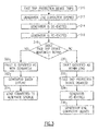
- Figure 3 illustrates a mode of operation of the generator 20, 120a, 120b.
- the fast trip protection device 22, 122 detects a fault within the system 10, 100 and trips in a "fast trip protection device trips" at 310.
- the tripped fast trip protection device 22, 122 causes the controller 26, 126 to open the generator line contactor 28, 128, thereby isolating the generator 20, 120a, 120b from the loads 40, 140 in a "generator line contactor opened" at 312.
- the generator 20, 120a, 120b is de-excited (powered down) in a "generator is de-excited" at 314.
- the generator 20, 120a, 120b is re-excited in a "generator is re-excited" at 316 to determine if the fast trip protection device 22, 122 retrips while isolated from the loads 40, 140 at "does fast trip device immediately retrip?" at 318. If the fast trip protection device 22, 122 retrips, the generator controller 26, 126 determines that a fault exists within the generator 20, 120a, 120b in a "fault is identified as within generator" at 320. When a fault is identified within the generator 20, 120a, 120b, the generator 20, 120a, 120b is taken offline by the controller 26, 126 in a "generator taken off line" at 322. The controller 26, 126 then connects an alternate power source such as an APU 60, 160, or a second generator 120a, 120b channel to the loads 40 in a "load connected to alternate power source" at 324.
- an alternate power source such as an APU 60, 160, or a second generator 120a, 120b channel to the loads 40 in
- the generator controller 26, 126 determines that the fault exists within the loads 140 and the tripping of the fast trip protection device 22, 122 was a nuisance trip in a "fault identified as within load" at 330.
- a nuisance trip occurs, it is imprudent to disconnect a functioning generator 20, 120a, 120b as the generator is still able to provide power, and the loads 40, 140 containing the fault may need power to clear the fault.
- the controller 26, 126 temporarily disables the fast trip protection device 22, 122 in a "fast trip protection device disabled” at 332 and then generator 20, 120 is re-excited in a "generator is re-excited” at 334.
- the controller then closes the generator line contactor 28, thereby reconnecting the generator 20, 120a, 120b to the loads 40, 140 in a "generator line contactor closed” at 336.
- the fast trip protection is temporarily disabled to prevent the load fault from re-tripping the power system.
- the duration of the temporary disablement of the fast trip protection is predetermined and stored within the controller 26, 126. Alternately, the duration can be determined a priori by the controller 26, 126 based on the number and types of connected loads 40, 140 at the time of the fault.
Abstract
Description
- Modern aircraft power generation systems often use variable frequency generators (VFGs). The VFGs are designed to carry required overloads at the lowest operating speeds of the VFGs. This results in the generator having a higher capacity at the highest operating speeds. As a result of this design consideration, some faults in a generator control unit or the generator can cause significant over voltages at higher operating speeds if the faults are not identified quickly.
- To protect against such faults, fast trip protection devices are included in the generator and trip whenever an overvoltage is present. Due to the fast nature of the fast trip protection devices, it is also possible for nuisance trips to occur. A nuisance trip occurs when a fault is present in the load and the fast trip protection device falsely detects a fault in the generator. When a nuisance trip occurs, it is imprudent to disconnect the generator from the load and connect an alternate power source.
- Disclosed is a method for responding to a fast protective trip in a generator system having the step of re-exciting the generator when a fast trip protection element trips and determining whether the generator retrips the fast trip protection element.
- Also disclosed is a method for responding to a fast trip protection trip device in a generator system comprising detecting a fast trip protection element tripping, isolating a generator from a load by opening a generator line contactor, de-exciting the generator, re-exciting the generator while the generator line contactor is open, connecting the load to an alternate power source when the generator retrips, determining the fast trip protection element trip is a nuisance trip when the generator re-excites without tripping the fast trip protection element, temporarily disabling the fast trip protection element when the trip is a nuisance trip, re-exciting the generator when the trip is a nuisance trip, reconnecting the generator to the load by closing the generator line contactor when the trip is a nuisance trip, re-enabling the fast trip protection element after a pre-determined duration when the trip is a nuisance trip.
- A power supply is defined as a generator and a generator line connection connecting the generator to a power distribution bus. The power distribution bus is operable to distribute power to at least one load. A fast trip protection device is incorporated into the generating source such that the fast trip protection device can detect a fault and open the generator line connection when a fault is detected. A controller is operable to control the generator and the fast trip protection device. The controller further has a computer readable means storing instructions for causing the power supply to perform the step of re-exciting the generator when a fast trip protection element trips and determining whether the generator immediately retrips the fast trip protection element.
- Various features will become apparent to those skilled in the art from the following detailed description of the disclosed non-limiting embodiment. The drawings that accompany the detailed description can be briefly described as follows:
-
Figure 1 illustrates a single channel power distribution system. -
Figure 2 illustrates a two channel power distribution system. -
Figure 3 illustrates an automatic fault isolation methodology that can be used with the illustrated examples ofFigures 1 and 2 . -
Figure 1 illustrates a single channelpower distribution system 10 having asingle generator 20 acting as a power source. Thegenerator 20 includes a fasttrip protection device 22 and acontroller 26. Apower output feeder 24 delivers electric power from thegenerator 20 to apower distribution bus 30 through agenerator contactor 28. Thegenerator contactor 28 is controlled via asignal line 27 from the fasttrip protection device 22.Multiple loads 40 are connected to thepower distribution bus 30 and receive operational power from thepower distribution bus 30 viapower connections 32. Typically, asecond generator 60 driven by an Auxiliary Power Unit (APU) provides a backup power source. Thesecond generator 60 is connected to thepower distribution bus 30 via agenerator contactor 68. Thepower output feeder 64 provides power from thesecond generator 60 to thegenerator contactor 68 throughline contactor 68. -
Figure 2 illustrates an alternative two channel configuration for apower distribution system 100. As with thepower distribution system 10 ofFigure 1 , each channel of thepower distribution system 100 has a generator 120a, 120b, with acontroller 126, and a fasttrip protection device 122. Each channel includes apower distribution bus 130 that provides power tomultiple loads 140. Each generator 120a, 120b is connected to the correspondingpower distribution bus 130 via apower output feeder 124, and a generator line control (GLC)switch 128. TheGLC switch 128 is controlled usingsignal lines 127 from the fasttrip protection devices 122. - The two channel configuration illustrated in
Figure 2 also includes abus tie connector 150 connected to eachpower distribution bus 130 via abus tie contactor 152. Anauxiliary power unit 160 is also connected to thebus tie connector 150 via an auxiliary generator line control (AGLC)switch 168 and apower feeder 162. Thebus tie contactor 152 can be controlled byswitch control lines 127 from either of the fasttrip protection devices 122 or an independent controller (not pictured). - With continued reference to
Figures 1 and 2 ,Figure 3 illustrates a mode of operation of thegenerator 20, 120a, 120b. Initially, the fasttrip protection device system trip protection device controller generator line contactor generator 20, 120a, 120b from theloads generator 20, 120a, 120b is de-excited (powered down) in a "generator is de-excited" at 314. - After being isolated and de-excited, the
generator 20, 120a, 120b is re-excited in a "generator is re-excited" at 316 to determine if the fasttrip protection device loads trip protection device generator controller generator 20, 120a, 120b in a "fault is identified as within generator" at 320. When a fault is identified within thegenerator 20, 120a, 120b, thegenerator 20, 120a, 120b is taken offline by thecontroller controller APU loads 40 in a "load connected to alternate power source" at 324. - Alternately, if the fast
trip protection device generator 20, 120a, 120b is re-excited, thegenerator controller loads 140 and the tripping of the fasttrip protection device generator 20, 120a, 120b as the generator is still able to provide power, and theloads load controller trip protection device generator 20, 120 is re-excited in a "generator is re-excited" at 334. The controller then closes thegenerator line contactor 28, thereby reconnecting thegenerator 20, 120a, 120b to theloads - The duration of the temporary disablement of the fast trip protection is predetermined and stored within the
controller controller loads power distribution system - It should be understood that like reference numerals identify corresponding or similar elements throughout the several drawings. It should also be understood that although a particular component arrangement is disclosed in the illustrated embodiment, other arrangements will benefit herefrom. Although particular step sequences are shown, described, and claimed, it should also be understood that steps may be performed in any order, separated or combined unless otherwise indicated and will still benefit from the present invention.
- Although the different examples have specific components shown in the illustrations, embodiments of this invention are not limited to those particular combinations. It is possible to use some of the components or features from one of the examples in combination with features or components from another one of the examples.
- The foregoing description is exemplary rather than defined by the limitations within. Various non-limiting embodiments are disclosed herein, however, one of ordinary skill in the art would recognize that various modifications and variations in light of the above teachings will fall within the scope of the appended claims. It is therefore to be understood that within the scope of the appended claims, the invention may be practiced other than as specifically described. For that reason the appended claims should be studied to determine true scope and content.
Claims (14)
- A method for responding to a fast protective trip in a generator system including a generator comprising:re-exciting the generator (20) when a fast trip protection element (22) trips and determining whether said generator retrips the fast trip protection element.
- The method of claim 1, further comprising: connecting a load (40) to an alternative power source (60) when said generator (20) retrips the fast trip protection element.
- The method of claim 1, further comprising: determining said fast trip protection element trip is a nuisance trip when said generator re-excites without tripping the fast trip protection element.
- The method of claim 3, further comprising: temporarily disabling said fast trip protection element.
- The method of claim 3, further comprising: re-exciting said generator after disabling said fast trip protection element.
- The method of claim 5, further comprising: reconnecting said generator to a load by closing a generator line contactor (28).
- The method of claim 4, further comprising: re-enabling said fast trip protection element after a pre-determined duration.
- The method of claim 1, further comprising:detecting a fast trip protection element tripping;isolating a generator from a load by opening a generator line contactor; andde-exciting the generator.
- A method for responding to a fast trip protection trip device in a generator system comprising:detecting a fast trip protection element (22) tripping;isolating a generator (20) from a load (40) by opening a generator line contactor;de-exciting the generator;re-exciting the generator while the generator line contactor is open;connecting said load to an alternative power source (60) when said generator retrips;determining said fast trip protection element trip is a nuisance trip when said generator re-excites without tripping the fast trip protection element;temporarily disabling said fast trip protection element when said trip is a nuisance trip;re-exciting said generator when said trip is a nuisance trip;reconnecting said generator to said load by closing said generator line contactor when said trip is a nuisance trip; andre-enabling said fast trip protection element after a pre-determined duration when said trip is a nuisance trip.
- A power supply comprising:a generator (20);a generator line connection (28) connecting said generator to a power distribution bus (30), wherein said power distribution bus is operable to distribute power to at least one load;a fast trip protection device (22) incorporated into said generator such that said fast trip protection device can detect a fault and open said generator line connection when a fault is detected; anda controller (26) operable to control said generator and said fast trip protection device, wherein said controller further comprises a computer readable means storing instructions for causing said power supply to perform the step of re-exciting the generator when a fast trip protection element trips and determining whether said generator immediately retrips the fast trip protection element.
- The power supply of claim 10, further comprising:a second generator (60) having a generator line connection (68) connecting said second generator to a second power distribution bus and a fast trip protection device operable to open said generator line connection upon detection of a fault;a bus tie connector (150) operable to electrically connect each of said first power distribution bus and said second power distribution bus; anda second generator controller (126) operable to control said second generator and said second fast trip protection device, wherein said second controller further comprises a computer readable means storing instructions for causing said power supply to perform the step of re-exciting the second generator when a fast trip protection element trips and determining whether said second generator immediately retrips the second fast trip protection element.
- The power supply of claim 10, further comprising an auxiliary power unit connected to said power distribution bus.
- The power distribution system of claim 10, wherein said controller is a generator controller integral to said first generator.
- The power distribution system of claim 10, wherein said controller is a generator controller external to said first generator.
Applications Claiming Priority (1)
| Application Number | Priority Date | Filing Date | Title |
|---|---|---|---|
| US13/447,266 US10432120B2 (en) | 2012-04-15 | 2012-04-15 | Automatic fault isolation methodology |
Publications (3)
| Publication Number | Publication Date |
|---|---|
| EP2651026A2 true EP2651026A2 (en) | 2013-10-16 |
| EP2651026A3 EP2651026A3 (en) | 2016-11-02 |
| EP2651026B1 EP2651026B1 (en) | 2023-10-18 |
Family
ID=48095677
Family Applications (1)
| Application Number | Title | Priority Date | Filing Date |
|---|---|---|---|
| EP13163489.1A Active EP2651026B1 (en) | 2012-04-15 | 2013-04-12 | Automatic fault isolation methodology |
Country Status (2)
| Country | Link |
|---|---|
| US (1) | US10432120B2 (en) |
| EP (1) | EP2651026B1 (en) |
Cited By (1)
| Publication number | Priority date | Publication date | Assignee | Title |
|---|---|---|---|---|
| EP3893347A3 (en) * | 2020-04-08 | 2021-10-20 | Hamilton Sundstrand Corporation | Arc fault induced differential protection isolation |
Families Citing this family (1)
| Publication number | Priority date | Publication date | Assignee | Title |
|---|---|---|---|---|
| US10491147B2 (en) * | 2017-11-29 | 2019-11-26 | Ford Global Technologies, Llc | Dual alternator vehicle power management |
Family Cites Families (19)
| Publication number | Priority date | Publication date | Assignee | Title |
|---|---|---|---|---|
| GB509261A (en) * | 1938-01-12 | 1939-07-12 | English Electric Co Ltd | Improvements in electric motor control systems |
| US2336836A (en) | 1942-11-30 | 1943-12-14 | Gen Electric | Automatic reclosing circuit breaker equipment |
| US2534895A (en) * | 1948-02-28 | 1950-12-19 | Westinghouse Electric Corp | Auxiliary power system for aircraft |
| US3234397A (en) * | 1962-08-27 | 1966-02-08 | Robert H Park | Means for maintaining stability of power transmission systems notwithstanding a fault |
| US3683199A (en) * | 1970-09-14 | 1972-08-08 | Westinghouse Electric Corp | Over-{11 and underexcitation protection circuit for alternating current power systems |
| JPS51144918A (en) * | 1975-06-10 | 1976-12-13 | Sawafuji Electric Co Ltd | A.c. power generator |
| JPS53120117A (en) | 1977-03-30 | 1978-10-20 | Hitachi Ltd | Excitation control system for generator |
| US4208693A (en) | 1978-03-15 | 1980-06-17 | Square D Company | Circuit breaker having an electronic fault sensing and trip initiating unit |
| FR2501929A1 (en) | 1981-03-10 | 1982-09-17 | Merlin Gerin | LOW VOLTAGE CIRCUIT BREAKER AND METHOD FOR MANUFACTURING A CURRENT SENSOR |
| US5422778A (en) | 1993-07-28 | 1995-06-06 | Sundstrand Corporation | Protection system for controller and control wiring induced under voltage faults in an electric power generating system |
| US5488532A (en) | 1993-10-27 | 1996-01-30 | Sundstrand Corporation | System of protection for electric power distribution failures |
| US5495381A (en) | 1994-11-22 | 1996-02-27 | Sundstrand Corporation | Protection system for undetected over voltage in an isolated voltage regulator |
| US5701070A (en) * | 1995-08-04 | 1997-12-23 | Onan Corporation | Electrical generator damage protection apparatus and method with circuit breaker trip initiation |
| US5710170A (en) | 1995-12-15 | 1998-01-20 | Merck Frosst Canada, Inc. | Tri-aryl ethane derivatives as PDE IV inhibitors |
| US5715124A (en) * | 1996-04-08 | 1998-02-03 | Sundstrand Corporation | System and method of isolation for detecting a passive protective function failure for an electric power generating system |
| US6088205A (en) | 1997-12-19 | 2000-07-11 | Leviton Manufacturing Co., Inc. | Arc fault detector with circuit interrupter |
| US7230344B2 (en) * | 2004-09-17 | 2007-06-12 | Rockwell Automation Technologies, Inc. | Apparatus and method for transient and uninterruptible power |
| US7359168B2 (en) | 2005-10-18 | 2008-04-15 | Eaton Corporation | Arc fault circuit interrupter and method for disabling series arc protection during current transients |
| US8970183B2 (en) * | 2011-01-14 | 2015-03-03 | Hamilton Sundstrand Corporation | Overvoltage limiter in an aircraft electrical power generation system |
-
2012
- 2012-04-15 US US13/447,266 patent/US10432120B2/en active Active
-
2013
- 2013-04-12 EP EP13163489.1A patent/EP2651026B1/en active Active
Non-Patent Citations (1)
| Title |
|---|
| None |
Cited By (2)
| Publication number | Priority date | Publication date | Assignee | Title |
|---|---|---|---|---|
| EP3893347A3 (en) * | 2020-04-08 | 2021-10-20 | Hamilton Sundstrand Corporation | Arc fault induced differential protection isolation |
| US11641101B2 (en) | 2020-04-08 | 2023-05-02 | Hamilton Sundstrand Corporation | Arc fault induced differential protection isolation |
Also Published As
| Publication number | Publication date |
|---|---|
| US20130271878A1 (en) | 2013-10-17 |
| EP2651026B1 (en) | 2023-10-18 |
| EP2651026A3 (en) | 2016-11-02 |
| US10432120B2 (en) | 2019-10-01 |
Similar Documents
| Publication | Publication Date | Title |
|---|---|---|
| EP2602893B1 (en) | Power system protection | |
| CN106066450B (en) | Insulation monitoring device with voltage monitoring and method based on same | |
| US9618586B2 (en) | Method and device for detection of a fault in a protected unit | |
| EP3148029B1 (en) | Fault protection devices and methods for power systems | |
| US10640000B2 (en) | Method and device for detecting a direct-current fault current | |
| CN106443301B (en) | System, method and device for detecting bipolar high-voltage direct-current ground fault | |
| KR20150020678A (en) | Digital protection relay, digital protection relay test device, and method for testing digital protection relay | |
| US8861147B2 (en) | Fault protection for aircraft power systems | |
| CN106329474B (en) | Protection device and method of operating the same, computer program product and electrical installation | |
| US11021065B2 (en) | High-voltage battery system having a safety device | |
| US9660435B2 (en) | Multi-directional electrical power protection system | |
| US9209616B2 (en) | Power supply circuit for on board energy source or storage device and particularly for super-capacitor storage unit | |
| CN101097818A (en) | Distance protection relay and method | |
| EP2651026B1 (en) | Automatic fault isolation methodology | |
| US20120098345A1 (en) | Minimal interruption dc power supply | |
| EP3618211B1 (en) | Direct current over voltage monitoring and protection | |
| EP2595268B1 (en) | Minimal interruption DC power supply | |
| US9136693B1 (en) | Generator with selectively bonded neutral connection | |
| US10759546B2 (en) | Transient voltage suppression protection circuit including built in testing and enable-disable functionality | |
| US8755159B2 (en) | System of current protection of a primary electrical distribution box | |
| JP2009219247A (en) | Standalone operation preventing system and control apparatus | |
| CN111193240B (en) | Control method and device of circuit breaker, rail transit traction control system and train | |
| WO2016002218A1 (en) | Leakage protection device and leakage protection system | |
| RU2521968C1 (en) | Damaged section determination method for sectionalised line of ring network | |
| JP2016152741A (en) | Ground directional relay |
Legal Events
| Date | Code | Title | Description |
|---|---|---|---|
| PUAI | Public reference made under article 153(3) epc to a published international application that has entered the european phase |
Free format text: ORIGINAL CODE: 0009012 |
|
| AK | Designated contracting states |
Kind code of ref document: A2 Designated state(s): AL AT BE BG CH CY CZ DE DK EE ES FI FR GB GR HR HU IE IS IT LI LT LU LV MC MK MT NL NO PL PT RO RS SE SI SK SM TR |
|
| AX | Request for extension of the european patent |
Extension state: BA ME |
|
| PUAL | Search report despatched |
Free format text: ORIGINAL CODE: 0009013 |
|
| AK | Designated contracting states |
Kind code of ref document: A3 Designated state(s): AL AT BE BG CH CY CZ DE DK EE ES FI FR GB GR HR HU IE IS IT LI LT LU LV MC MK MT NL NO PL PT RO RS SE SI SK SM TR |
|
| AX | Request for extension of the european patent |
Extension state: BA ME |
|
| RIC1 | Information provided on ipc code assigned before grant |
Ipc: H02P 9/10 20060101AFI20160926BHEP Ipc: H02H 7/06 20060101ALI20160926BHEP Ipc: H02H 3/06 20060101ALI20160926BHEP |
|
| 17P | Request for examination filed |
Effective date: 20170502 |
|
| RBV | Designated contracting states (corrected) |
Designated state(s): AL AT BE BG CH CY CZ DE DK EE ES FI FR GB GR HR HU IE IS IT LI LT LU LV MC MK MT NL NO PL PT RO RS SE SI SK SM TR |
|
| STAA | Information on the status of an ep patent application or granted ep patent |
Free format text: STATUS: REQUEST FOR EXAMINATION WAS MADE |
|
| STAA | Information on the status of an ep patent application or granted ep patent |
Free format text: STATUS: EXAMINATION IS IN PROGRESS |
|
| STAA | Information on the status of an ep patent application or granted ep patent |
Free format text: STATUS: EXAMINATION IS IN PROGRESS |
|
| 17Q | First examination report despatched |
Effective date: 20201014 |
|
| STAA | Information on the status of an ep patent application or granted ep patent |
Free format text: STATUS: EXAMINATION IS IN PROGRESS |
|
| GRAP | Despatch of communication of intention to grant a patent |
Free format text: ORIGINAL CODE: EPIDOSNIGR1 |
|
| STAA | Information on the status of an ep patent application or granted ep patent |
Free format text: STATUS: GRANT OF PATENT IS INTENDED |
|
| INTG | Intention to grant announced |
Effective date: 20230522 |
|
| RAP3 | Party data changed (applicant data changed or rights of an application transferred) |
Owner name: HAMILTON SUNDSTRAND CORPORATION |
|
| GRAS | Grant fee paid |
Free format text: ORIGINAL CODE: EPIDOSNIGR3 |
|
| GRAA | (expected) grant |
Free format text: ORIGINAL CODE: 0009210 |
|
| STAA | Information on the status of an ep patent application or granted ep patent |
Free format text: STATUS: THE PATENT HAS BEEN GRANTED |
|
| AK | Designated contracting states |
Kind code of ref document: B1 Designated state(s): AL AT BE BG CH CY CZ DE DK EE ES FI FR GB GR HR HU IE IS IT LI LT LU LV MC MK MT NL NO PL PT RO RS SE SI SK SM TR |
|
| REG | Reference to a national code |
Ref country code: GB Ref legal event code: FG4D |
|
| REG | Reference to a national code |
Ref country code: CH Ref legal event code: EP |
|
| REG | Reference to a national code |
Ref country code: IE Ref legal event code: FG4D |
|
| REG | Reference to a national code |
Ref country code: DE Ref legal event code: R096 Ref document number: 602013084804 Country of ref document: DE |
|
| REG | Reference to a national code |
Ref country code: LT Ref legal event code: MG9D |
|
| REG | Reference to a national code |
Ref country code: NL Ref legal event code: MP Effective date: 20231018 |
|
| REG | Reference to a national code |
Ref country code: AT Ref legal event code: MK05 Ref document number: 1623361 Country of ref document: AT Kind code of ref document: T Effective date: 20231018 |
|
| PG25 | Lapsed in a contracting state [announced via postgrant information from national office to epo] |
Ref country code: NL Free format text: LAPSE BECAUSE OF FAILURE TO SUBMIT A TRANSLATION OF THE DESCRIPTION OR TO PAY THE FEE WITHIN THE PRESCRIBED TIME-LIMIT Effective date: 20231018 |
|
| PG25 | Lapsed in a contracting state [announced via postgrant information from national office to epo] |
Ref country code: GR Free format text: LAPSE BECAUSE OF FAILURE TO SUBMIT A TRANSLATION OF THE DESCRIPTION OR TO PAY THE FEE WITHIN THE PRESCRIBED TIME-LIMIT Effective date: 20240119 |
|
| PG25 | Lapsed in a contracting state [announced via postgrant information from national office to epo] |
Ref country code: IS Free format text: LAPSE BECAUSE OF FAILURE TO SUBMIT A TRANSLATION OF THE DESCRIPTION OR TO PAY THE FEE WITHIN THE PRESCRIBED TIME-LIMIT Effective date: 20240218 |
|
| PG25 | Lapsed in a contracting state [announced via postgrant information from national office to epo] |
Ref country code: LT Free format text: LAPSE BECAUSE OF FAILURE TO SUBMIT A TRANSLATION OF THE DESCRIPTION OR TO PAY THE FEE WITHIN THE PRESCRIBED TIME-LIMIT Effective date: 20231018 |