EP2650977B1 - Electrical connector assembly - Google Patents
Electrical connector assembly Download PDFInfo
- Publication number
- EP2650977B1 EP2650977B1 EP13176310.4A EP13176310A EP2650977B1 EP 2650977 B1 EP2650977 B1 EP 2650977B1 EP 13176310 A EP13176310 A EP 13176310A EP 2650977 B1 EP2650977 B1 EP 2650977B1
- Authority
- EP
- European Patent Office
- Prior art keywords
- female
- electrode
- male
- electrical connector
- receptacle
- Prior art date
- Legal status (The legal status is an assumption and is not a legal conclusion. Google has not performed a legal analysis and makes no representation as to the accuracy of the status listed.)
- Active
Links
Images






Classifications
-
- H—ELECTRICITY
- H01—ELECTRIC ELEMENTS
- H01R—ELECTRICALLY-CONDUCTIVE CONNECTIONS; STRUCTURAL ASSOCIATIONS OF A PLURALITY OF MUTUALLY-INSULATED ELECTRICAL CONNECTING ELEMENTS; COUPLING DEVICES; CURRENT COLLECTORS
- H01R13/00—Details of coupling devices of the kinds covered by groups H01R12/70 or H01R24/00 - H01R33/00
- H01R13/02—Contact members
- H01R13/10—Sockets for co-operation with pins or blades
- H01R13/11—Resilient sockets
-
- H—ELECTRICITY
- H01—ELECTRIC ELEMENTS
- H01R—ELECTRICALLY-CONDUCTIVE CONNECTIONS; STRUCTURAL ASSOCIATIONS OF A PLURALITY OF MUTUALLY-INSULATED ELECTRICAL CONNECTING ELEMENTS; COUPLING DEVICES; CURRENT COLLECTORS
- H01R13/00—Details of coupling devices of the kinds covered by groups H01R12/70 or H01R24/00 - H01R33/00
- H01R13/64—Means for preventing incorrect coupling
- H01R13/642—Means for preventing incorrect coupling by position or shape of contact members
-
- H—ELECTRICITY
- H01—ELECTRIC ELEMENTS
- H01R—ELECTRICALLY-CONDUCTIVE CONNECTIONS; STRUCTURAL ASSOCIATIONS OF A PLURALITY OF MUTUALLY-INSULATED ELECTRICAL CONNECTING ELEMENTS; COUPLING DEVICES; CURRENT COLLECTORS
- H01R13/00—Details of coupling devices of the kinds covered by groups H01R12/70 or H01R24/00 - H01R33/00
- H01R13/02—Contact members
-
- H—ELECTRICITY
- H01—ELECTRIC ELEMENTS
- H01R—ELECTRICALLY-CONDUCTIVE CONNECTIONS; STRUCTURAL ASSOCIATIONS OF A PLURALITY OF MUTUALLY-INSULATED ELECTRICAL CONNECTING ELEMENTS; COUPLING DEVICES; CURRENT COLLECTORS
- H01R13/00—Details of coupling devices of the kinds covered by groups H01R12/70 or H01R24/00 - H01R33/00
- H01R13/02—Contact members
- H01R13/15—Pins, blades or sockets having separate spring member for producing or increasing contact pressure
- H01R13/187—Pins, blades or sockets having separate spring member for producing or increasing contact pressure with spring member in the socket
-
- H—ELECTRICITY
- H01—ELECTRIC ELEMENTS
- H01R—ELECTRICALLY-CONDUCTIVE CONNECTIONS; STRUCTURAL ASSOCIATIONS OF A PLURALITY OF MUTUALLY-INSULATED ELECTRICAL CONNECTING ELEMENTS; COUPLING DEVICES; CURRENT COLLECTORS
- H01R13/00—Details of coupling devices of the kinds covered by groups H01R12/70 or H01R24/00 - H01R33/00
- H01R13/02—Contact members
- H01R13/26—Pin or blade contacts for sliding co-operation on one side only
-
- H—ELECTRICITY
- H01—ELECTRIC ELEMENTS
- H01R—ELECTRICALLY-CONDUCTIVE CONNECTIONS; STRUCTURAL ASSOCIATIONS OF A PLURALITY OF MUTUALLY-INSULATED ELECTRICAL CONNECTING ELEMENTS; COUPLING DEVICES; CURRENT COLLECTORS
- H01R13/00—Details of coupling devices of the kinds covered by groups H01R12/70 or H01R24/00 - H01R33/00
- H01R13/64—Means for preventing incorrect coupling
-
- H—ELECTRICITY
- H01—ELECTRIC ELEMENTS
- H01R—ELECTRICALLY-CONDUCTIVE CONNECTIONS; STRUCTURAL ASSOCIATIONS OF A PLURALITY OF MUTUALLY-INSULATED ELECTRICAL CONNECTING ELEMENTS; COUPLING DEVICES; CURRENT COLLECTORS
- H01R13/00—Details of coupling devices of the kinds covered by groups H01R12/70 or H01R24/00 - H01R33/00
- H01R13/40—Securing contact members in or to a base or case; Insulating of contact members
- H01R13/405—Securing in non-demountable manner, e.g. moulding, riveting
- H01R13/41—Securing in non-demountable manner, e.g. moulding, riveting by frictional grip in grommet, panel or base
-
- H—ELECTRICITY
- H01—ELECTRIC ELEMENTS
- H01R—ELECTRICALLY-CONDUCTIVE CONNECTIONS; STRUCTURAL ASSOCIATIONS OF A PLURALITY OF MUTUALLY-INSULATED ELECTRICAL CONNECTING ELEMENTS; COUPLING DEVICES; CURRENT COLLECTORS
- H01R13/00—Details of coupling devices of the kinds covered by groups H01R12/70 or H01R24/00 - H01R33/00
- H01R13/46—Bases; Cases
- H01R13/465—Identification means, e.g. labels, tags, markings
Definitions
- the present invention generally relates to electrical connectors and, more particularly, to high current electrical connectors with protection against reverse polarity connections.
- a wide variety of electronic devices are powered through the use of battery packs.
- remotely controlled vehicles of all types may have an onboard rechargeable battery pack supplying stored electricity to an electric motor.
- racing creates a demand for more powerful motors along with increasing levels of current capacity to energize the motors.
- a battery pack is drained of the stored energy contained therein, a user must be able to easily exchange a depleted battery pack for a fully charged one. The depleted battery pack is then connected to a battery charger in order to be ready for the next exchange. Consequently, there exists a need for a high current electrical connector with a lightweight and compact design.
- An embodiment of the present invention provides an electrical connector according to claim 1.
- FIG. 1 shows a top orthogonal view of an assembled electrical connector with attached wire conductors.
- reference numeral 1000 generally indicates an illustrative embodiment of an electrical connector 1000 at least partially configured according to the present invention.
- the electrical connector 1000 may comprise a female member 100 and a male member 500. Attached to the electrical connector 1000 are wire conductors 10A, 10B, 20A, and 20B.
- the wire conductors 10A, 10B, 20A, and 20B may not considered as components of the electrical connector 1000 and are shown for the purposes of illustration.
- Wire conductors 10A and 10B may carry a positive current flow and wire conductors 20A and 20B may carry a negative current flow.
- the various components of the electrical connector 1000 will be described in more detail in the following illustrative embodiment.
- the female member 100 may comprise a female housing 102, a first and second female terminal 200, and a first and second resilient member 300.
- the male member 500 may comprise a male housing 502, and a first and second male terminal 600.
- the female member 100 may comprise a female housing 102, a first female terminal chamber 110, a second female terminal chamber 120, female terminals 200, and resilient members 300 (more clearly shown in FIG. 2 ).
- a first female polarity indicator 111 and a second female polarity indicator 121 may indicate the respective polarities of the first female terminal chamber 110 and the second female terminal chamber 120.
- a first orifice 116 and a second orifice 126 may be located at an end of the female member 100 opposite to the first and second female polarity indicators 111 and 121.
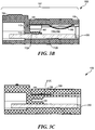
- An example of a resilient member 300 is shown in FIGS. 3B and 3C .
- a resilient member 300 may be located in each of the first and second female terminal chambers 110 and 120 (however, only one is shown in the FIGS. 3B and 3C for the purposes of illustration). The various components of the female member 100 will be described in more detail in the following illustrative embodiment.
- the female housing 102 may be substantially rectangular in shape and comprise a female conductor housing 104, a female internal wall 105, and a female terminal housing 106, for each of the first and second female terminal chambers 110 and 120. Due to symmetry, only the first female terminal chamber 110 will be described from this point forward, reference numerals enclosed by parenthesis refer to the second female terminal chamber 120. Although a substantially rectangular shape is shown for the female housing 102, embodiments of the present invention may not be limited to this one configuration. Any configuration capable of accommodating one or more female terminals 200 may be used.
- the female housing 102 may be manufactured from a dielectric material able to withstand the operating conditions of an intended application and provide sufficient electrical insulation between the current carrying female terminals 200 (i.e., inhibiting the occurrence of electrical shorts between the female terminals 200).
- the material of the female housing 102 may be a glass reinforced nylon such as Zytel® 70G33L, made by DuPont®. In some applications the reinforced nylon material may comprise approximately 33% glass.
- the material may be used in a remotely controlled vehicle operating in a natural environment for example and may experience a temperature range from below -20° F (-29° C) to over 250° F (121° C) (e.g., when operated in desert conditions over solar heated roadways, or due to battery heat, current flow, and electrical resistance).
- the female conductor housing 104 may be separated from the female terminal housing 106 by the female internal wall 105.
- the female internal wall 105 may comprise an opening 114 (124) to accommodate a female terminal 200.
- the female internal wall 105 may comprise an indicator 113 identifying the connection side of the electrical connector 1000 ( FIG. 1 ) for example (e.g., "A" for the female member and "B" for the male member).
- the indicator 113 may comprise a polarity sign to be used in place of, or in addition to, the first and second female polarity indicators 111 and 121 ( FIG. 3A ).
- the female conductor housing 104 may circumferentially surround an end of a female terminal 200 inserted into each of the first and second female terminal chambers 110 and 120.
- An end of the female conductor housing 104 opposing the female internal wall 105 may be open to provide access for a conductor (not shown) to contact an exposed end of a female terminal 200.
- an end or side of the female conductor housing 104 adjacent to the female internal wall 105 may be open to provide conductor access.
- the female conductor housing 104 substantially shrouds and insulates the ends of the female terminals 200 from each other.
- the female conductor housing 104 may only partially surround an end of a female terminal 200 in each of the first and second female terminal chambers 110 and 120.
- the female terminal housing 106 portions of each of the first and second female terminal chambers 110 and 120 may comprise a female terminal support 107 and a resilient member support 109 ( FIG. 3C ). Each of the female terminal supports 107 may help to retain a corresponding female terminal 200 in the respective first and second female terminal chambers 110 and 120.
- the female terminal support 107 may comprise one or more retention members 112 (for example as represented by 112A) configured to retain a female terminal 200 after assembly into a female member 100. Although a slanted ramp type of retention member 112 is shown in FIG. 3B to facilitate an insertion type of assembly (e.g., inserting a female terminal 200 from left to right in the female housing 102 with respect to FIG.
- a person of ordinary skill in the art would not be limited to just this type of retention member 112.
- Pins, rivets, fasteners, other mechanical attachments, welding, and chemical adhesives, among other various methods may be used to secure a female terminal 200 in the female housing 102.
- similar additional retention members 112B may be used to provide additional force to oppose the friction force generated during the assembly and disassembly of the electrical connector 1000 ( FIG. 1 ) that may otherwise move or dislocate one or both of the female terminals 200.
- Other embodiments of the female member 100 may not comprise retention members 112. In some cases the female terminals 200 and resilient members 300 may be core molded into the female member 100 at the time of manufacture.
- the resilient member support 109 may secure a resilient member 300 in each of the first and second female terminal chambers 110 and 120.
- the resilient member support 109 is shown as proximate to the female internal wall 105. However, an embodiment of the resilient member support 109 may be located proximate to an end of the female terminal housing 106 opposite to the female internal wall 105 (i.e., the insertion end of the female terminal housing 106, for example, essentially configured 180° in a horizontal plane relative to the embodiment shown in FIG. 3B ) in addition to other locations.
- the resilient member support 109 may comprise one or more retention features 112, for example, as represented by 112C in FIG. 3C .
- the retention features 112 of the resilient member support 109 may comprise slanted ramp protrusions as with an embodiment of the female terminal support 107, or the retention features 112 may comprise any of the mechanical, chemical, or welding methods of fastening previously recited.
- the previously recited methods of retaining and/or fastening female terminals 200 and resilient members 300 are not intended to form an exhaustive list, but are merely a sampling from amongst a broad variety of retaining and fastening methods known to those of ordinary skill in the art.
- the resilient members 300 may be core molded into the female housing 102 during the production of the female housing 102.
- first and second female terminal chambers 110 and 120 located in the female terminal housing 106, opposite to the female internal wall 105 are referred to as the first and second orifices 116 and 126.
- Each of the first and second orifices 116 and 126 may be configured substantially in a rectangular shape as shown in FIG. 3A .
- an aspect of the first orifice 116 such as a width, may be configured differently than the same aspect of the second orifice 126. The difference in widths may inhibit an incorrectly polarized assembly of a male member 500 ( FIG. 1 ) with the female member 100.
- the present invention may not be limited to this method. Different configurations, devices, and dimensions may be used to facilitate the proper polar connection orientation during assembly of a male member 500 with a female member 100.
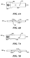
- FIG. 4A shows a top view of an embodiment of a female terminal 200
- FIG. 4B shows a side view of the female terminal 200 of FIG. 4A
- the female terminal 200 may comprise a terminal connector portion 204 and a terminal contact portion 206.
- the female terminal 200 may comprise an electrically conductive material, such as brass, copper, or bronze.
- the female terminal 200 may be plated with gold (such as a gold-cobalt or gold-nickel alloy) or silver, among other materials, preferably copper plated with nickel and then plated with gold (for example), in order to increase the electrical conductivity between contacting portions of the male and female terminals 600 and 200.
- the female terminal 200 shown may be made from a standard plate of material and punched formed to the correct size and configuration, among other methods of forming.
- the terminal connector portion 204 may be located on one end of the female terminal 200 and configured to electrically couple with a copper wire conductor (for example) such as wire conductors 10B and 20B ( FIG. 1 ).
- the terminal connector portion 204 may be electrically coupled to a wire conductor through the use of soldering, mechanical fastening (e.g., through the use of a screw clamp), standard insulated and non-insulated connector fittings, crimping, and other methods of electrically coupling a wire conductor to a portion of a terminal.
- Embodiments of the terminal connector portion 204 may comprise a variety of configurations in order to accommodate a particular electrical coupling method.
- the terminal contact portion 206 may be located at an opposite end of the female terminal 200 relative to the terminal connector portion 204, and may comprise an angled end 210, one or more terminal retention features 212 (two are shown in FIG. 4B , 212A and 212B), and a contact surface 214.
- the angled end 210 may help facilitate the coupling or assembly of a corresponding male terminal 600 ( FIG. 2 ) during the connection of an electrical connector 1000 ( FIG. 1 ).
- the contact surface 214 may directly contact an opposing surface of a male terminal 600 in order to allow an electrical current to flow from one end of the electrical connector 1000 to the other.
- Terminal step 208 may separate the terminal connector portion 204 from the terminal contact portion 206.
- the terminal step 208 may oppose a portion of the female housing 102 and prevent further movement in the assembly direction.
- the terminal retention features 212 may contact corresponding retention features 112 of the female housing 102 and prevent movement in a direction opposite to the assembly direction.
- the female terminal 200 may be substantially securely coupled with the female housing 102.
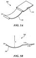
- the resilient member 300 may comprise a resilient base member 310 and a resilient contact member 320.
- the resilient member 300 may be punch formed from a sheet of stainless steel (e.g., SS 301 with no plating), spring steel (e.g., spring steel with nickel plating) or other resilient material configured to work within the anticipated environmental conditions of the electrical connector 1000 ( FIG. 1 ).
- the resilient member 300 may be plated or otherwise coated to inhibit rust or to provide an appropriate level of resistance (e.g., friction force) necessary to maintain the connection between an assembled male member 500 and female member 100.
- the resilient base member 310 may be located at one end of the resilient member 300 and comprise one or more resilient retention members 312A and 312B ( FIG. 5B ).
- the resilient retention members 312A and 312B may engage corresponding retention members 112 within the resilient member support 109 (as seen in FIG. 3C , but only one retention member 112C can be seen in this view), located in each of the first and second terminal chambers 110 and 120.
- the resilient retention members 312A and 312B may securely retain the resilient members 300 within the female housing 102 during assembly and disassembly of the electrical connector 1000 ( FIG. 1 ).
- the resilient base member 310 is shown as a substantially flat quadrilateral but embodiments of the present invention may not be limited to this illustrative form.
- the resilient base member 310 may be retained separate from the corresponding female terminal 200 and separate from a fully inserted male terminal 500 ( FIG. 2 ). In other words, the resilient base member 310 may not overlay a corresponding male terminal 500 when an electrical connector 1000 ( FIG. 1 ) is electrically coupled.
- the resilient contact member 320 may comprise an arcuate portion defined by a radius R.
- the arcuate portion may be resiliently deformed toward the radial center point in response to pressure or interference from portions of an installed male member 500 ( FIG. 1 ).
- the arcuate portion may also be configured to interface with a depression or other engaging feature, detailed later, in an opposing surface or portion of the male member 500 in order to provide a disassembly retention force after coupling the male member 500 with the female member 100 (see FIG. 1 ).
- FIGS. 5A and 5B only a single arcuate portion is illustrated in FIGS. 5A and 5B .
- embodiments of the present invention are not to be limited to this one exemplary configuration.
- radii either alone or in combination with one or more relatively straight portions may be used, an arcuate portion curving back upon the resilient contact member 320, a single angular bend joining two straight portions together, or a plurality of angular or arcuate portions such as in a zig-zag or wave type of configuration may be used in order to more evenly apply a force from the female member 100 to the male member 500.
- the listing is intended to provide a small representative sample of the various potential configurations consistent with the present invention and is not intended to be exhaustive.
- One end of the resilient contact member 320 may comprise a housing interface 324.
- An example of the housing interface 324 may be illustrated by a small radius curve rotating in an opposite direction relative to the arcuate portion defined by the radius R.
- the housing interface 324 may facilitate a sliding movement along a contacting portion of an inner wall of the female housing 102 ( FIG. 3B ) in response to assembly and disassembly of a male member 500 and a female member 100 (see FIG. 2 ).
- the sliding contact may prevent or inhibit the abrading or prematurely wearing down of the inner surface of the female housing 102 over a multiple number of connections and disconnections of the electrical connector 1000 ( FIG. 1 ).
- the contacting portion of the housing interface 324 curves away from the inner surface of the female housing 102 in directions tangent to the small radius curve.
- the resilient contact member 320 may extend at an angle from the resilient base member 310 such that the housing interface 324 may be located above (with respect to FIG. 5B ) a plane containing the resilient base member 310. This configuration may apply a pre-load to an assembled resilient member 300 via the housing interface 324.
- the angle for the resilient contact member 320 relative to the resilient base member 310, and/or adjusting the radius R the force applied to the male member 500 through the resilient contact member 320 may be adjusted. Adjusting the force of the resilient contact member 320 may adjust the amount of insertion and withdrawal force for the connecting and disconnecting of the electrical connector 1000. Consequently, a desired amount of insertion and withdrawal force may be established for the connecting and disconnecting of the electrical connector 1000.
- the male member 500 may comprise a male housing 502, a first male terminal extension 510, a second male terminal extension 520, and male terminals 600 (more clearly shown in FIG. 6B ).
- a first male polarity indicator 511 and a second male polarity indicator 521 may indicate the respective polarities of the first male terminal extension 510 and the second male terminal extension 520.
- An example of a male terminal 600 is shown in FIGS. 7A and 7B and is detailed later. The various components of the male member 500 will be described in more detail in the following illustrative embodiment.
- the male housing 502 may be substantially rectangular in shape and comprise a male conductor housing 504, a male internal wall 505, and a male terminal tip 506 for each of the first and second male terminal extensions 510 and 520. Due to their similarities, only the first male terminal extension 510 will be described from this point forward, reference numerals enclosed by parenthesis refer to second male terminal extension 520. Although a substantially rectangular shape is shown for the male housing 502, embodiments of the present invention may not be limited to this one configuration. Any configuration capable of accommodating one or more male terminals 600 may be used.
- the male housing 502 may be manufactured from a dielectric material able to withstand the operating conditions of an intended application and provide sufficient electrical insulation between the current carrying male terminals 600 (i.e., inhibiting the occurrence of an electrical short between the male terminals 600).
- the material of the male housing 502 may be a glass reinforced nylon such as Zytel® 70G33L, made by DuPont®. In some applications the reinforced nylon material may comprise approximately 33% glass.
- the material may be used in a remotely controlled vehicle operating in a natural environment for example and may experience a temperature range from below -20° F (-29° C) to over 250° F (121° C) (e.g., when operated in desert conditions over solar heated roadways, or due to battery heat, current flow, and electrical resistance).
- the male conductor housing 504 may be separated from the male terminal housing 506 by the male internal wall 505.
- the male internal wall 505 may comprise an opening 514 (524) to accommodate a male terminal 600.
- the male internal wall 505 may comprise an indicator 513 identifying the connection side of the electrical connector 1000 ( FIG. 1 ), for example (e.g., "A" for the female member and "B” for the male member).
- the indicator 513 may comprise a polarity sign to be used in place of, or in addition to, the first and second male polarity indicators 511 and 521 ( FIG. 6A ).
- the male conductor housing 504 may circumferentially surround an end of a male terminal 600 inserted into each of the first and second male terminal extensions 510 and 520.
- An end of the male conductor housing 504 opposing the internal wall 505 may be open to provide access for a conductor (not shown) to contact an exposed end of a male terminal 600.
- an end or side of the male conductor housing 504 adjacent to the male internal wall 505 may be open to provide conductor access.
- the male conductor housing 504 substantially shrouds and insulates the ends of the male terminals 600 from each other.
- the male conductor housing 504 may only partially surround an end of a male terminal 600 in each of the first and second male terminal extensions 510 and 520.
- the male internal wall 505 of each of the first and second male terminal extensions 510 and 520 may function as a male terminal support ( FIG. 6B ).
- Each of the male terminal supports i.e., male internal walls 505) may help to retain a corresponding male terminal 600 in the respective first and second male terminal extensions 510 and 520.
- the male terminal support may comprise one or more retention members 512 (for example as represented by 512A), configured to retain a male terminal 600 after assembly into a male member 500. Although a slanted ramp type of retention member 512 is shown in FIG. 6B to facilitate an insertion type of assembly (e.g., inserting a male terminal 600 from the left to the right in the male housing 502 with respect to FIG.
- retention member 512 a person of ordinary skill in the art would not be limited to just this type of retention member 512.
- Pins, rivets, fasteners, other mechanical attachments, welding, and chemical adhesives, among other various methods may be used to secure a male terminal 600 within the male housing 502.
- similar additional retention members 512B may be used to provide additional force to oppose the friction force generated during the connection and disconnection of the electrical connector 1000 ( FIG. 1 ) that may otherwise move or dislocate one or both of the male terminals 600.
- Other embodiments of the male member 500 may not comprise retention members 512.
- the male terminals 600 may be core molded into the male housing 502 at the time of manufacture.
- first and second male terminal covers 516 and 526 The ends of the first and second male terminal extensions 510 and 520 in the male terminal tips 506, opposite to the internal wall 505, are referred to as the first and second male terminal covers 516 and 526.
- Each of the first and second male terminal covers 516 and 526 may be configured substantially in a rectangular shape as shown in FIG. 6A .
- an aspect of the first male terminal cover 516 for example width, may be configured differently than the same aspect of the second male terminal cover 526. The difference in widths may inhibit an incorrectly polarized assembly of a male member 500 ( FIG. 1 ) with the female member 100.
- the present invention may not be limited to this method. Different configurations, devices, and dimensions may be used to facilitate the proper polar connection orientation during assembly of a male member 500 with a female member 100.
- the first and second male terminal covers 516 and 526 may each comprise a connector retention feature 507.
- the connector retention feature 507 may be configured as an arcuate cavity or depression corresponding to an arcuate portion of the resilient contact member 320 of a resilient member 300 (see FIG. 5B ).
- the resilient member 300 moves relative to a surface of the corresponding first and second male terminal covers 516 and 526 until a portion of the resilient contact member 320 engages a corresponding portion of the connector retention feature 507.
- the engagement between the resilient contact member 320 and the connector retention feature 507 may provide a sensory indication that the male member 500 is fully connected to the female member 100.
- the engagement between the resilient contact member 320 and the connector retention feature 507 may help to prevent inadvertent disconnection between the male member 500 and the female member 100 during the operation of the electrical connector 1000 in an applied device.
- the first and second male terminal covers 516 and 526 may further comprise an angled or slanted portion 570, which may be located at an end opposite to the male internal wall 505.
- the slanted portion 570 of each of the first and second male terminal covers 516 and 526 may facilitate the insertion and/or assembly of the male member 500 with the female member 100 (see FIG. 1 ).
- rounded, arcuate, or other insertion facilitating features may be used in place of, or in addition to, the slanted portion 570 of each of the first and second male terminal covers 516 and 526.
- At least part of the remaining portions of the first and second male terminal covers 516 and 526 may provide a contact surface for the resilient member 300, as previously explained, and may provide a degree of insulation between the resilient members 300 and the male terminals 600.
- the material of the first and second male terminal covers 516 and 526 may be the same as the material used for the rest of the male housing 502.
- the first and second male terminal covers 516 and 526 may comprise a coating applied to a surface of the male terminals 600.
- a coating or texture may be applied to a surface of the first and second male terminal covers 516 and 526 to vary the level of frictional resistance between the surface and the contacting portion of the resilient contact member 320 of each of the respective resilient members 300.
- FIG. 7A shows a top view of an embodiment of a male terminal 600
- FIG. 7B shows a side view of the male terminal 600 of FIG. 7A
- the male terminal 600 may comprise a terminal connector portion 604 and a terminal contact portion 606.
- the male terminal 600 may comprise an electrically conductive material, such as brass, copper, or bronze.
- the male terminal 600 may be plated with gold (such as gold-cobalt or gold-nickel alloy) or silver, among other materials, preferably copper plated with nickel and then plated with gold (for example), in order to increase the electrical conductivity between contacting portions of the male and female terminals 600 and 200.
- the male terminal 600 shown may be made from a standard plate of material and punched formed to the correct size and configuration, among other methods of forming.
- the terminal connector portion 604 may be located on one end of the male terminal 600 and configured to electrically couple with a copper wire conductor (for example) such as wire conductors 10A and 20A ( FIG. 1 ).
- the terminal connector portion 604 may be electrically coupled to a wire conductor through the use of soldering, mechanical fastening (e.g., through the use of a screw clamp), standard insulated and non-insulated connector fittings, crimping, and other methods of electrically coupling a wire conductor to a terminal.
- Embodiments of the terminal connector portion 604 may comprise a variety of configurations in order to accommodate a particular electrical coupling method.
- the terminal contact portion 606 may be located at an opposite end of the male terminal 600 relative to the terminal connector portion 604, and may comprise an angled end 610, one or more terminal retention features 612 (two are shown in FIG. 7B , 612A and 612B), and a contact surface 614.
- the angled end 610 may help facilitate the coupling or assembly of a corresponding female terminal 200 ( FIG. 2 ) during the connection of an electrical connector 1000 ( FIG. 1 ).
- the contact surface 614 may directly contact an opposing surface of a female terminal 200 in order to allow an electrical current to flow from one end of the electrical connector 1000 to the other.
- Terminal step 608 may separate the terminal connector portion 604 from the terminal contact portion 606.
- the terminal step 608 may oppose a portion of the male housing 502 and prevent further movement in the assembly direction.
- the terminal retention features 612 may contact corresponding retention features 512 of the male housing 502 and prevent movement in a direction opposite to the assembly direction.
- the male terminal 600 may be substantially securely coupled with the male housing 502.
- FIG. 8A illustrates a correctly assembled electrical connector 1000
- FIG. 8B illustrates an incorrectly assembled electrical connector 1000
- the first and second male polarity indicators 511 and 521 correspond to the first and second female polarity indicators 111 and 121, indicating the maintenance of proper polarity across the electrical connector 1000.
- the correspondence between the sets of polarity indicators 111, 121, 511, and 521 may provide a visual indication of the correct coupling of the male and female members 500 and 100.
- FIG. 8A illustrates a correctly assembled electrical connector 1000
- FIG. 8B illustrates an incorrectly assembled electrical connector 1000.
- the first and second male polarity indicators 511 and 521 correspond to the first and second female polarity indicators 111 and 121, indicating the maintenance of proper polarity across the electrical connector 1000.
- the correspondence between the sets of polarity indicators 111, 121, 511, and 521 may provide a visual indication of the correct coupling of the male and female members 500 and 100.
- the first and second male polarity indicators 511 and 521 may not be visible from a top oriented viewing plane when the male member 500 is incorrectly assembled to the female member 100.
- the polarities on each side of the incorrectly assembled electrical connector 1000 have been reversed.
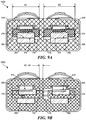
- FIG. 9A illustrates a cross-sectional view of the correctly assembled electrical connector 1000 of FIG. 8A as viewed along line 9A-9A
- FIG.9B illustrates a cross-sectional view of the incorrectly assembled electrical connector 1000 of FIG. 8B as viewed along line 9B-9B
- FIG. 9A shows an electrical connector 1000 in which a first male terminal cover 516 is inserted into a first orifice 116 and a contact surface 614 of the male terminal 600 is abutting a contact surface 214 of the female terminal 200.
- the first male terminal cover 516 and the first orifice 116 may each have an approximate width of W1 with the first male terminal cover 516 configured to fit within the first orifice 116.
- the second male terminal cover 526 is inserted into a second orifice 126 such that a contact surface 614 of the corresponding male terminal 600 is abutting a contact surface 214 of the corresponding female terminal 200.
- the second male terminal cover 526 and the second orifice 126 may each have an approximate width of W2 with the second male terminal cover 526 configured to fit within the second orifice 126.
- the width W1 may be smaller than the width W2. This difference in widths may provide another method of inhibiting or preventing cross-polarization during connection of the male member 500 to the female member 100 ( FIG. 8A ), since the male member 500 may be connected to the female member 100 when the male member 500 is properly oriented with respect to the female member 100.
- the proper orientation of the male and female members 500 and 100 may provide for the correct polarity of the connection.
- FIG. 9B shows an electrical connector 1000 in which a male member 500 is incorrectly connected to a female member 100.
- This type of connection may be substantially prevented by the interference between the width of the second male terminal cover 526 (W2) and the width of the first orifice 116 (W1) (e.g., W2-W1).
- W2 the width of the second male terminal cover 526
- W1 the width of the first orifice 116
- cross-polarization of the electrical connector 1000 may still be prevented by the first and second male terminal covers 516 and 526 separating the male and female terminals 600 and 200.
- the first and second male terminal covers 516 and 526 may prevent contact between corresponding male and female terminals 600 and 200 when the male member 500 is in a second orientation with respect to the female member 100.
- cross-polarization of the electrical connector 1000 may be prevented and/or inhibited by at least two separate and independent methods, in addition to the visual indication given by the first and second male and female polarity indicators, 111, 121, 511, and 521.
- FIG. 10 this figure illustrates an orthogonal cross-sectional view of a correctly assembled male member 500 and female member 100.
- the first and second male terminal extensions 510 and 520 ( FIG. 6A ) have been inserted into the first and second female terminal chambers 110 and 120 ( FIG. 3A ), or more specifically, the male terminal housing 506 portions of the first and second male terminal extensions 510 and 520 have been inserted into the first and second orifices 116 and 126 of the first and second female terminal chambers 110 and 120.
- the resilient members 300 may initially contact the slanted portion 570 of the corresponding first and second male terminal covers 516 and 526.
- the resilient contact portions 320 may respectively slidingly engage a top surface of each of the first and second male terminal covers 516 and 526.
- the resilient contact portions 320 may be compressed, causing the housing interface 324 portion of the resilient member 300 to slidingly engage an interior surface of the respective first and second female terminal chambers 110 and 120.
- the male member 500 may continue to be inserted into the female member 100 until the resilient contact portion 320 engages a corresponding connector retention feature 507 of the respective first and second male terminal covers 516 and 526. At this point, the male member 500 may be securely coupled to the female member 100.
- the other side portion may be similar due to the symmetry of the connector. However, complete symmetry is not a limitation required of an embodiment of the present invention and differences beyond the widths of the first and second male terminal covers 516 and 526 and corresponding first and second orifices 116 and 126 may exist.
- FIG. 11 shows an orthogonal top view with a cross-section taken through the side of an embodiment of an electrical connector.
- reference number 2000 generally refers to another illustrative embodiment of an electrical connector 2000 constructed according to aspects of the present invention.
- One difference between the electrical connector 2000 and the previously described electrical connector 1000 ( FIG. 1 ) may be the replacement of one or more resilient members 300 ( FIG. 2 ) of the previous illustrative embodiment with one or more resilient members 2300. Otherwise, the function and materials for the two electrical connectors 1000 and 2000 may be considered to be the same. Similar components may be identified with similar reference numerals used in the previous description, and a detailed explanation of these components may not be repeated.
- Electrical connector 2000 may comprise a female member 2100 and a male member 500, shown here in a connected state.
- the female member 2100 may comprise one or more female terminals 200 (only one is visible in this view) and the male member 500 may comprise a corresponding number of male terminals 600.
- electricity may be able to flow between wire conductors (not shown) through the electrical connector 2000 via the areas of contact between the female and male terminals 200 and 600.
- the female member 2100 may comprise one or more resilient members 2300.
- the resilient members 2300 may provide a pressing force to facilitate electrical conduction through the contact areas between the corresponding female and male terminals 200 and 600.
- the resilient members 2300 may provide a securing force to inhibit or prevent the inadvertent disconnection of the male member 500 from the female member 2100 during the use of the electrical connector 2300 in a desired application (e.g., such as in a vibratory and dynamic environment of a remotely controlled vehicle).
- the number of resilient members 2300 corresponds to the number of electrical connections formed or broken during the connection and disconnection of the electrical connector 2000 (e.g., two are shown in FIG. 11 ). However, the number of resilient members 2300 may not be required to equal the number of electrical connections formed or broken.
- Each resilient member 2300 may comprise a resilient housing 2310 integrated with the housing of the female member 2100. As shown in FIG. 11 , the resilient housing 2310 may be substantially cylindrical for example, but embodiments of the present invention may not be limited to this geometric configuration. Each resilient member 2300 may further comprise a retention device 2324, a resilient device 2322, and a contact device 2320.
- the retention device 2324 may comprise an Allen set screw as shown for example, or may comprise any of a number of devices able to retain the resilient device 2322 and the contact device 2320 within the resilient housing 2310, while in some embodiments further providing a measure of adjustability. For example, a mechanical threaded fastener, angled key, or cam device, among others, may be used. In this example, the retention device 2324 may be threadably engaged with a top portion of the resilient housing 2310.
- the resilient device 2322 may be located between the retention device 2324 and the contact device 2320.
- the resilient device 2322 may be a spring, such as a coil spring, or resilient material, such as foam, among other devices.
- the resilient device 2322 may press against the contact device 2320, facilitating movement of the contact device 2320 as the male member 500 and the female member 2100 are coupled together.
- the force applied to the contact device 2320 and consequently to the male and female terminals 200 and 600 may be adjusted by tightening or loosening the retention device 2324, in addition to altering the spring stiffness or material, among other methods.
- the male member 500 may be securely coupled to the female member 2100 by tightening the retention device 2324 so as to eliminate or reduce the ability of the contact device 2320 to move within the resilient housing 2310, thereby forcefully engaging the contact device 2320 with a connector retention feature 507.
- the contact device 2320 may be spherical ball for example, such as in a ball and spring type of mechanism. However, in other embodiments the contact device 2320 may be any member capable of moving across the surface of the first and second male terminal covers 516 and 526 (only the first male terminal cover 516 is visible in this view), such as a rounded pin, angled member, cylinder, among others.
- the contact device 2320 may be retained within the resilient housing 2310 between a protruding edge 2312 at one end and the retention device 2324 at the other end. During connection of the male member 500 and the female member 2100, the contact device 2320 may engage the connector retention feature 507 as the male member 500 is fully coupled with the female member 2100.
- the contact device 2320 and the connector retention feature 507 may be configured to have corresponding or interfacing features, such that when the male member 500 is fully coupled with the female member 2100, a sensory indication of the application device 2320 engaging the connector retention feature 507 may be provided.
- the sensory indication may be visual, audible, tactile, or a combination of one or more of these sensory indications, in addition to other methods.
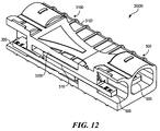
- FIG. 12 this figure shows an orthogonal top view with a cross-section taken through the side of an embodiment of an electrical connector.
- reference number 3000 generally refers to another illustrative embodiment of an electrical connector 3000 constructed according to aspects of the present invention.
- One difference between the electrical connector 3000 and the previously described electrical connectors may be the replacement of one or more resilient members 300 ( FIG. 2 ) or 2300 ( FIG. 11 ) of the previous illustrative embodiments, with one or more resilient members 3300.
- the function and materials for the electrical connectors 1000, 2000, and 3000 may be considered to be the same. Similar components may be identified with similar reference numerals used in the previous description, and a detailed explanation of these components may not be repeated.
- Electrical connector 3000 may comprise a female member 3100 and a male member 500, shown here in a connected state.
- the female member 3100 may comprise one or more female terminals 200 (only one is visible in this view) and the male member 500 may comprise a corresponding number of male terminals 600.
- electricity may be able to flow between wire conductors (not shown) through the electrical connector 3000 via the contact areas between the female and male terminals 200 and 600.
- the female member 3100 may comprise one or more resilient members 3300.
- the resilient members 3300 may provide a pressing force to facilitate electrical conduction through the contact area between the female terminals 200 and the male terminals 600.
- the resilient members 3300 may provide a securing force to inhibit or prevent the inadvertent disconnection of the male member 500 from the female member 3100 during the use of the electrical connector 3300 in a desired application (e.g., such as in a vibratory and dynamic remotely controlled vehicle).
- the number of resilient members 3300 corresponds to the number of electrical connections formed or broken during the connection and disconnection of the electrical connector 3000, two electrical connections are shown in this embodiment. However, the number of resilient members 3300 may not be required to equal the number of electrical connections formed or broken.
- Each resilient member 3300 may be configured to interfere with a opposing surface of a first and second male terminal cover 516 and 526 (only 516 is visible in this view) when a male member 500 is coupled to a female member 3100.
- the area indicated by cross-hatching may be the area of interference between the resilient member 3300 and the top surface of the first male terminal cover 516, although only a portion of the abutting surfaces may be configured to be interfering.
- the resilient member 3300 may comprise a rib interfacing with a portion of the respective top surface of the first and second male terminal covers 516 and 526, or the resilient member 3300 may comprise the wall of the female member housing 3102, among numerous other configurations such as those previously described for the resilient contact portion 320.
- the housing 3102 of the female member 3100 may function as a resilient member, allowing at least some degree of resilient deformation or movement designed to apply a force to at least a portion of an installed male member 500 (e.g., such as the first and second male terminal covers 516 and 526, or in some embodiments, the male terminals themselves, among other configurations).
- the first and second male terminal covers 516 and 526 may function as a resilient member, allowing at least some degree of resilient deformation or movement designed to urge the male terminals 600 together with the corresponding female terminals 200.
- both the female housing 3102 and the first and second male terminal covers 516 and 526 may experience some degree of resilient deformation, combining together to provide a force urging the male terminals 600 together with the corresponding female terminals 200.
- the resilient member 3300 may further comprise protrusions or features configured to engage with corresponding depressions or features located on the top surfaces of the first and second male terminal covers 516 and 526, such that the male member 500 may be securely coupled to the female member 3100 upon fully connecting the male member 500 to the female member 3100.
- An example of a protrusion for the resilient member 3300 may be an arcuate ridge corresponding to the connector retention feature 507 shown in FIG. 6B .
- the resilient member 3300 may at least partially resiliently deform with respect to the area of interference. Alternatively, the resilient member 3300 may take advantage of at least some degree of resilient deformation in the configuration of the female member housing 3102.
- FIGS. 13A and 13B the first figure shows a top view of an illustrative embodiment of a male member 1500 configured according to aspects of the present invention, while the second figure shows an orthogonal cross-sectional top view of the male member 1500 of FIG. 13A as viewed along line 13B-13B.
- One difference between the male member 1500 and the previously described male member 500 ( FIG. 1 ) may be the lack of first and second male terminal covers 516 and 526 (see FIGS. 6A and 6B ) in the male member 1500.
- Another difference may be the use of first and second male terminals 1600 and 1650 in male member 1500 in place of the male terminals 600 shown in male member 500 (see FIG. 2 ).
- the function and materials for the male members 500 and 1500 may be considered to be substantially the same. Similar components may be identified with similar reference numerals used in previous descriptions, and a detailed explanation of these components may not be repeated.
- Male member 1500 may comprise a male housing 1502 and first and second male terminal extensions 1510 and 1520.
- the first male terminal extension 1510 may comprise the first male terminal 1600
- the second male terminal extension 1520 may comprise the second male terminal 1650.
- First and second male terminals 1600 and 1650 may be configured to be insertably engaged with the first and second orifices 116 and 126 of the first and second female terminal chambers 110 and 120 of a female member 100 (see FIG. 3A ).
- some aspects of the first male terminal 1600 may be different than similar aspects of the second male terminal 1650 in order to inhibit the cross-polarizing connection of a male member 1500 and a female member 100.
- the width W1 of the first male terminal 1600 may be smaller that the width W2 of the second male terminal 1650. Interference between the larger width W2 and the first orifice 116 may inhibit the connection between a female member 100 and an improperly oriented male member 1500 (i.e., the male member 1500 may be improperly oriented with respect to the female member 100).
- the male housing 1502 may be substantially rectangular in shape and comprise a male conductor housing 504 and a male internal wall 1505 for each of the first and second male terminal extensions 1510 and 1520. Although a substantially rectangular shape is shown for the male housing 1502, embodiments of the present invention may not be limited to this one configuration. Any configuration capable of accommodating one or more first and second male terminals 1600 and 1650 may be used.
- the male housing 1502 may be manufactured from a dielectric material able to withstand the operating conditions of an intended application and provide sufficient electrical insulation between the current carrying first male terminal 1600 and second male terminal 1650 (i.e., inhibiting the occurrence of an electrical short between the first male terminal 1600 and the second male terminal 1650).
- the male internal wall 1505 of each of the first and second male terminal extensions 1510 and 1520 may function as a male terminal support.
- Each of the male terminal supports i.e., male internal walls 1505 may respectively secure and support the first and second male terminals 1600 and 1650 in the corresponding first and second male terminal extensions 1510 and 1520.
- the male terminal support may comprise one or more retention members 512 (for example as represented by 512A and 512B) configured to retain the respective first and second male terminals 1600 and 1650 after assembly into a male member 1500. Although a slanted ramp type of retention member 512 is shown in FIG. 13B to facilitate an insertion type of assembly (e.g., inserting a male terminal 1600 from the right to the left in the male housing 1502 with respect to FIG.
- first and second male terminals 1600 and 1650 may be core molded along with the male housing 1502 at the time of manufacture.
- the first and second male terminals 1600 and 1650 may comprise retention members 612 (for example as represented by 612A and 612B, however, only the retention members 612 of the first male terminal 1600 may be seen in FIG. 13B , the second male terminal 1650 may be similarly configured) corresponding to the retention members 512.
- retention members 612 for example as represented by 612A and 612B, however, only the retention members 612 of the first male terminal 1600 may be seen in FIG. 13B , the second male terminal 1650 may be similarly configured
- a slanted ramp type of retention member 612 is shown in FIG. 13B to facilitate an insertion type of assembly, however, a person of ordinary skill in the art would not be limited to just this type of retention member 612.
- Pins, rivets, fasteners, other mechanical attachments, welding, and chemical adhesives, among other various methods may be used to secure the first and second male terminals 1600 and 1650 within the male housing 1502.
Landscapes
- Connector Housings Or Holding Contact Members (AREA)
- Details Of Connecting Devices For Male And Female Coupling (AREA)
- Coupling Device And Connection With Printed Circuit (AREA)
Description
- The present invention generally relates to electrical connectors and, more particularly, to high current electrical connectors with protection against reverse polarity connections.
- A wide variety of electronic devices are powered through the use of battery packs. For example, remotely controlled vehicles of all types may have an onboard rechargeable battery pack supplying stored electricity to an electric motor. In some of these lightweight vehicles, racing creates a demand for more powerful motors along with increasing levels of current capacity to energize the motors. As a battery pack is drained of the stored energy contained therein, a user must be able to easily exchange a depleted battery pack for a fully charged one. The depleted battery pack is then connected to a battery charger in order to be ready for the next exchange. Consequently, there exists a need for a high current electrical connector with a lightweight and compact design.
- Document
US 4 737 118 discloses a connector according to the preamble of claim 1. - An embodiment of the present invention provides an electrical connector according to claim 1.
- For a more complete understanding of the present invention and the advantages thereof, reference is now made to the following Detailed Description taken in conjunction with the accompanying drawings, in which:
-
FIG. 1 illustrates a general orthogonal top view of an embodiment of an electrical connector configured according to the present invention and showing attached wire conductors; -
FIG. 2 illustrates an exploded assembly view of the electrical connector ofFIG. 1 ; -
FIG. 3A illustrates an orthogonal top view of a female member of the electrical connector ofFIG. 1 ; -
FIG. 3B illustrates a cross-sectional view of the female member ofFIG. 3A as viewed alongline 3B-3B; -
FIG. 3C illustrates a cross-sectional view of the female member ofFIG. 3A as viewed alongline 3C-3C; -
FIG. 4A illustrates a top view of a female terminal; -
FIG. 4B illustrates a side view of the female terminal ofFIG. 4A ; -
FIG. 5A illustrates an orthogonal top view of a resilient member; -
FIG. 5B illustrates a side view of the resilient member ofFIG. 5A ; -
FIG. 6A illustrates an orthogonal top view of a male member; -
FIG. 6B illustrates a cross-sectional side view of the male member ofFIG. 6A ; -
FIG. 7A illustrates a top view of a male terminal; -
FIG. 7B illustrates a side view of the male terminal ofFIG. 7A ; -
FIG. 8A illustrates an orthogonal top view of the electrical connector ofFIG. 1 correctly assembled; -
FIG. 8B illustrates an orthogonal top view of the electrical connector ofFIG. 1 incorrectly assembled; -
FIG. 9A illustrates a cross-sectional view of the correctly assembled electrical connector ofFIG. 8A as viewed alongline 9A-9A; -
FIG. 9B illustrates a cross-sectional view of the incorrectly assembled electrical connector ofFIG. 8B as viewed alongline 9B-9B; -
FIG. 10 illustrates an orthogonal cross-sectional view of the assembled electrical connector ofFIG. 1 ; -
FIG. 11 illustrates an orthogonal cross-sectional top view of another embodiment of an electrical connector configured according to aspects of the present invention; -
FIG. 12 illustrates an orthogonal cross-sectional top view of another embodiment of an electrical connector configured according to aspects of the present invention; -
FIG. 13A illustrates a top view of another embodiment of a component of an electrical connector configured according to aspects of the present invention; and -
FIG. 13B illustrates an orthogonal cross-sectional top view of the component ofFIG. 13A as viewed alongline 13B-13B. - In the following discussion, numerous specific details are set forth to provide a thorough understanding of the present invention. However, those skilled in the art will appreciate that the present invention may be practiced without such specific details. In other instances, well-known elements have been illustrated in schematic or block diagram form in order not to obscure the present invention in unnecessary detail. Additionally, for the most part, details concerning well known features and elements have been omitted inasmuch as such details are not considered necessary to obtain a complete understanding of the present invention, and are considered to be within the understanding of persons of ordinary skill in the relevant art.
- Turning now to the drawings,
FIG. 1 shows a top orthogonal view of an assembled electrical connector with attached wire conductors. In this drawing,reference numeral 1000 generally indicates an illustrative embodiment of anelectrical connector 1000 at least partially configured according to the present invention. Theelectrical connector 1000 may comprise afemale member 100 and amale member 500. Attached to theelectrical connector 1000 arewire conductors wire conductors electrical connector 1000 and are shown for the purposes of illustration.Wire conductors wire conductors electrical connector 1000 will be described in more detail in the following illustrative embodiment. - Referring to
FIG. 2 , the components of an embodiment of theelectrical connector 1000 are shown in an exploded assembly view. Thefemale member 100 may comprise afemale housing 102, a first and secondfemale terminal 200, and a first and secondresilient member 300. Themale member 500 may comprise amale housing 502, and a first and secondmale terminal 600. - Turning now to
FIGS. 3A ,3B, and 3C , thefemale member 100 may comprise afemale housing 102, a first femaleterminal chamber 110, a second femaleterminal chamber 120,female terminals 200, and resilient members 300 (more clearly shown inFIG. 2 ). A firstfemale polarity indicator 111 and a secondfemale polarity indicator 121 may indicate the respective polarities of the first femaleterminal chamber 110 and the second femaleterminal chamber 120. Afirst orifice 116 and asecond orifice 126 may be located at an end of thefemale member 100 opposite to the first and secondfemale polarity indicators resilient member 300 is shown inFIGS. 3B and 3C . Aresilient member 300 may be located in each of the first and second femaleterminal chambers 110 and 120 (however, only one is shown in theFIGS. 3B and 3C for the purposes of illustration). The various components of thefemale member 100 will be described in more detail in the following illustrative embodiment. - Referring to
FIG. 3B , thefemale housing 102 may be substantially rectangular in shape and comprise afemale conductor housing 104, a femaleinternal wall 105, and a femaleterminal housing 106, for each of the first and second femaleterminal chambers terminal chamber 110 will be described from this point forward, reference numerals enclosed by parenthesis refer to the second femaleterminal chamber 120. Although a substantially rectangular shape is shown for thefemale housing 102, embodiments of the present invention may not be limited to this one configuration. Any configuration capable of accommodating one or morefemale terminals 200 may be used. Thefemale housing 102 may be manufactured from a dielectric material able to withstand the operating conditions of an intended application and provide sufficient electrical insulation between the current carrying female terminals 200 (i.e., inhibiting the occurrence of electrical shorts between the female terminals 200). For example, the material of thefemale housing 102 may be a glass reinforced nylon such as Zytel® 70G33L, made by DuPont®. In some applications the reinforced nylon material may comprise approximately 33% glass. The material may be used in a remotely controlled vehicle operating in a natural environment for example and may experience a temperature range from below -20° F (-29° C) to over 250° F (121° C) (e.g., when operated in desert conditions over solar heated roadways, or due to battery heat, current flow, and electrical resistance). - The
female conductor housing 104 may be separated from the femaleterminal housing 106 by the femaleinternal wall 105. The femaleinternal wall 105 may comprise an opening 114 (124) to accommodate afemale terminal 200. On thefemale conductor housing 104 side of the femaleinternal wall 105, the femaleinternal wall 105 may comprise anindicator 113 identifying the connection side of the electrical connector 1000 (FIG. 1 ) for example (e.g., "A" for the female member and "B" for the male member). In other embodiments, theindicator 113 may comprise a polarity sign to be used in place of, or in addition to, the first and secondfemale polarity indicators 111 and 121 (FIG. 3A ). - The
female conductor housing 104 may circumferentially surround an end of afemale terminal 200 inserted into each of the first and second femaleterminal chambers female conductor housing 104 opposing the femaleinternal wall 105 may be open to provide access for a conductor (not shown) to contact an exposed end of afemale terminal 200. In other embodiments, an end or side of thefemale conductor housing 104 adjacent to the femaleinternal wall 105 may be open to provide conductor access. In the embodiment shown, thefemale conductor housing 104 substantially shrouds and insulates the ends of thefemale terminals 200 from each other. In certain other embodiments thefemale conductor housing 104 may only partially surround an end of afemale terminal 200 in each of the first and second femaleterminal chambers - The female
terminal housing 106 portions of each of the first and second femaleterminal chambers terminal support 107 and a resilient member support 109 (FIG. 3C ). Each of the female terminal supports 107 may help to retain a correspondingfemale terminal 200 in the respective first and second femaleterminal chambers terminal support 107 may comprise one or more retention members 112 (for example as represented by 112A) configured to retain afemale terminal 200 after assembly into afemale member 100. Although a slanted ramp type of retention member 112 is shown inFIG. 3B to facilitate an insertion type of assembly (e.g., inserting afemale terminal 200 from left to right in thefemale housing 102 with respect toFIG. 3B ), a person of ordinary skill in the art would not be limited to just this type of retention member 112. Pins, rivets, fasteners, other mechanical attachments, welding, and chemical adhesives, among other various methods may be used to secure afemale terminal 200 in thefemale housing 102. Further, similaradditional retention members 112B may be used to provide additional force to oppose the friction force generated during the assembly and disassembly of the electrical connector 1000 (FIG. 1 ) that may otherwise move or dislocate one or both of thefemale terminals 200. Other embodiments of thefemale member 100 may not comprise retention members 112. In some cases thefemale terminals 200 andresilient members 300 may be core molded into thefemale member 100 at the time of manufacture. - The resilient member support 109 (
FIG. 3C ) may secure aresilient member 300 in each of the first and second femaleterminal chambers resilient member support 109 is shown as proximate to the femaleinternal wall 105. However, an embodiment of theresilient member support 109 may be located proximate to an end of the femaleterminal housing 106 opposite to the female internal wall 105 (i.e., the insertion end of the femaleterminal housing 106, for example, essentially configured 180° in a horizontal plane relative to the embodiment shown inFIG. 3B ) in addition to other locations. As with the femaleterminal support 107, theresilient member support 109 may comprise one or more retention features 112, for example, as represented by 112C inFIG. 3C . The retention features 112 of theresilient member support 109 may comprise slanted ramp protrusions as with an embodiment of the femaleterminal support 107, or the retention features 112 may comprise any of the mechanical, chemical, or welding methods of fastening previously recited. The previously recited methods of retaining and/or fasteningfemale terminals 200 andresilient members 300 are not intended to form an exhaustive list, but are merely a sampling from amongst a broad variety of retaining and fastening methods known to those of ordinary skill in the art. As with thefemale terminals 200, theresilient members 300 may be core molded into thefemale housing 102 during the production of thefemale housing 102. - The ends of the first and second female
terminal chambers terminal housing 106, opposite to the femaleinternal wall 105, are referred to as the first andsecond orifices second orifices FIG. 3A . However, in the illustrative embodiment shown in these figures, an aspect of thefirst orifice 116, such as a width, may be configured differently than the same aspect of thesecond orifice 126. The difference in widths may inhibit an incorrectly polarized assembly of a male member 500 (FIG. 1 ) with thefemale member 100. Although a difference in dimensional aspects such as widths may be used to inhibit reversing the polarities during connection of an electrical connector 1000 (FIG. 1 ) the present invention may not be limited to this method. Different configurations, devices, and dimensions may be used to facilitate the proper polar connection orientation during assembly of amale member 500 with afemale member 100. - Turning now to
FIGS. 4A and 4B, FIG. 4A shows a top view of an embodiment of afemale terminal 200, andFIG. 4B shows a side view of thefemale terminal 200 ofFIG. 4A . As an example of an illustrative embodiment of afemale terminal 200, thefemale terminal 200 may comprise aterminal connector portion 204 and aterminal contact portion 206. Thefemale terminal 200 may comprise an electrically conductive material, such as brass, copper, or bronze. Thefemale terminal 200 may be plated with gold (such as a gold-cobalt or gold-nickel alloy) or silver, among other materials, preferably
copper plated with nickel and then plated with gold (for example), in order to increase the electrical conductivity between contacting portions of the male andfemale terminals female terminal 200 shown may be made from a standard plate of material and punched formed to the correct size and configuration, among other methods of forming. - The
terminal connector portion 204 may be located on one end of thefemale terminal 200 and configured to electrically couple with a copper wire conductor (for example) such aswire conductors FIG. 1 ). Theterminal connector portion 204 may be electrically coupled to a wire conductor through the use of soldering, mechanical fastening (e.g., through the use of a screw clamp), standard insulated and non-insulated connector fittings, crimping, and other methods of electrically coupling a wire conductor to a portion of a terminal. Embodiments of theterminal connector portion 204 may comprise a variety of configurations in order to accommodate a particular electrical coupling method. - The
terminal contact portion 206 may be located at an opposite end of thefemale terminal 200 relative to theterminal connector portion 204, and may comprise anangled end 210, one or more terminal retention features 212 (two are shown inFIG. 4B , 212A and 212B), and acontact surface 214. Theangled end 210 may help facilitate the coupling or assembly of a corresponding male terminal 600 (FIG. 2 ) during the connection of an electrical connector 1000 (FIG. 1 ). Thecontact surface 214 may directly contact an opposing surface of amale terminal 600 in order to allow an electrical current to flow from one end of theelectrical connector 1000 to the other. -
Terminal step 208 may separate theterminal connector portion 204 from theterminal contact portion 206. In some embodiments, during assembly of thefemale terminal 200 into female housing 102 (FIG. 3B ), theterminal step 208 may oppose a portion of thefemale housing 102 and prevent further movement in the assembly direction. The terminal retention features 212 may contact corresponding retention features 112 of thefemale housing 102 and prevent movement in a direction opposite to the assembly direction. At this point, thefemale terminal 200 may be substantially securely coupled with thefemale housing 102. - Referring now to
FIGS. 5A and 5B , these figures respectively show an orthogonal top view of aresilient member 300 and a side view of theresilient member 300 ofFIG. 5A . Theresilient member 300 may comprise aresilient base member 310 and aresilient contact member 320. Theresilient member 300 may be punch formed from a sheet of stainless steel (e.g., SS 301 with no plating), spring steel (e.g., spring steel with nickel plating) or other resilient material configured to work within the anticipated environmental conditions of the electrical connector 1000 (FIG. 1 ). In some embodiments, theresilient member 300 may be plated or otherwise coated to inhibit rust or to provide an appropriate level of resistance (e.g., friction force) necessary to maintain the connection between an assembledmale member 500 andfemale member 100. - The
resilient base member 310 may be located at one end of theresilient member 300 and comprise one or moreresilient retention members FIG. 5B ). Theresilient retention members FIG. 3C , but only oneretention member 112C can be seen in this view), located in each of the first and secondterminal chambers resilient retention members resilient members 300 within thefemale housing 102 during assembly and disassembly of the electrical connector 1000 (FIG. 1 ). Theresilient base member 310 is shown as a substantially flat quadrilateral but embodiments of the present invention may not be limited to this illustrative form. Theresilient base member 310 may be retained separate from the correspondingfemale terminal 200 and separate from a fully inserted male terminal 500 (FIG. 2 ). In other words, theresilient base member 310 may not overlay a correspondingmale terminal 500 when an electrical connector 1000 (FIG. 1 ) is electrically coupled. - As more easily seen in
FIG. 5B , theresilient contact member 320 may comprise an arcuate portion defined by a radius R. The arcuate portion may be resiliently deformed toward the radial center point in response to pressure or interference from portions of an installed male member 500 (FIG. 1 ). The arcuate portion may also be configured to interface with a depression or other engaging feature, detailed later, in an opposing surface or portion of themale member 500 in order to provide a disassembly retention force after coupling themale member 500 with the female member 100 (seeFIG. 1 ). In the illustrative embodiment shown, only a single arcuate portion is illustrated inFIGS. 5A and 5B . However, embodiments of the present invention are not to be limited to this one exemplary configuration. For example, larger and smaller radii either alone or in combination with one or more relatively straight portions may be used, an arcuate portion curving back upon theresilient contact member 320, a single angular bend joining two straight portions together, or a plurality of angular or arcuate portions such as in a zig-zag or wave type of configuration may be used in order to more evenly apply a force from thefemale member 100 to themale member 500. The listing is intended to provide a small representative sample of the various potential configurations consistent with the present invention and is not intended to be exhaustive. - One end of the
resilient contact member 320 may comprise ahousing interface 324. An example of thehousing interface 324 may be illustrated by a small radius curve rotating in an opposite direction relative to the arcuate portion defined by the radius R. Thehousing interface 324 may facilitate a sliding movement along a contacting portion of an inner wall of the female housing 102 (FIG. 3B ) in response to assembly and disassembly of amale member 500 and a female member 100 (seeFIG. 2 ). The sliding contact may prevent or inhibit the abrading or prematurely wearing down of the inner surface of thefemale housing 102 over a multiple number of connections and disconnections of the electrical connector 1000 (FIG. 1 ). In this example, the contacting portion of thehousing interface 324 curves away from the inner surface of thefemale housing 102 in directions tangent to the small radius curve. Further, theresilient contact member 320 may extend at an angle from theresilient base member 310 such that thehousing interface 324 may be located above (with respect toFIG. 5B ) a plane containing theresilient base member 310. This configuration may apply a pre-load to an assembledresilient member 300 via thehousing interface 324. By adjusting the angle for theresilient contact member 320 relative to theresilient base member 310, and/or adjusting the radius R, the force applied to themale member 500 through theresilient contact member 320 may be adjusted. Adjusting the force of theresilient contact member 320 may adjust the amount of insertion and withdrawal force for the connecting and disconnecting of theelectrical connector 1000. Consequently, a desired amount of insertion and withdrawal force may be established for the connecting and disconnecting of theelectrical connector 1000. - Turning now to
FIGS. 6A, and 6B , themale member 500 may comprise amale housing 502, a first maleterminal extension 510, a second maleterminal extension 520, and male terminals 600 (more clearly shown inFIG. 6B ). A firstmale polarity indicator 511 and a secondmale polarity indicator 521 may indicate the respective polarities of the first maleterminal extension 510 and the second maleterminal extension 520. An example of amale terminal 600 is shown inFIGS. 7A and 7B and is detailed later. The various components of themale member 500 will be described in more detail in the following illustrative embodiment. - Referring to
FIG. 6B , themale housing 502 may be substantially rectangular in shape and comprise amale conductor housing 504, a maleinternal wall 505, and a maleterminal tip 506 for each of the first and secondmale terminal extensions terminal extension 510 will be described from this point forward, reference numerals enclosed by parenthesis refer to second maleterminal extension 520. Although a substantially rectangular shape is shown for themale housing 502, embodiments of the present invention may not be limited to this one configuration. Any configuration capable of accommodating one or moremale terminals 600 may be used. Themale housing 502 may be manufactured from a dielectric material able to withstand the operating conditions of an intended application and provide sufficient electrical insulation between the current carrying male terminals 600 (i.e., inhibiting the occurrence of an electrical short between the male terminals 600). For example, the material of themale housing 502 may be a glass reinforced nylon such as Zytel® 70G33L, made by DuPont®. In some applications the reinforced nylon material may comprise approximately 33% glass. The material may be used in a remotely controlled vehicle operating in a natural environment for example and may experience a temperature range from below -20° F (-29° C) to over 250° F (121° C) (e.g., when operated in desert conditions over solar heated roadways, or due to battery heat, current flow, and electrical resistance). - The
male conductor housing 504 may be separated from the maleterminal housing 506 by the maleinternal wall 505. The maleinternal wall 505 may comprise an opening 514 (524) to accommodate amale terminal 600. On themale conductor housing 504 side of the maleinternal wall 505, the maleinternal wall 505 may comprise anindicator 513 identifying the connection side of the electrical connector 1000 (FIG. 1 ), for example (e.g., "A" for the female member and "B" for the male member). In other embodiments, theindicator 513 may comprise a polarity sign to be used in place of, or in addition to, the first and secondmale polarity indicators 511 and 521 (FIG. 6A ). - The
male conductor housing 504 may circumferentially surround an end of amale terminal 600 inserted into each of the first and secondmale terminal extensions male conductor housing 504 opposing theinternal wall 505 may be open to provide access for a conductor (not shown) to contact an exposed end of amale terminal 600. In other embodiments, an end or side of themale conductor housing 504 adjacent to the maleinternal wall 505 may be open to provide conductor access. In the embodiment shown, themale conductor housing 504 substantially shrouds and insulates the ends of themale terminals 600 from each other. In certain other embodiments themale conductor housing 504 may only partially surround an end of amale terminal 600 in each of the first and secondmale terminal extensions - The male
internal wall 505 of each of the first and secondmale terminal extensions FIG. 6B ). Each of the male terminal supports (i.e., male internal walls 505) may help to retain a correspondingmale terminal 600 in the respective first and secondmale terminal extensions male terminal 600 after assembly into amale member 500. Although a slanted ramp type of retention member 512 is shown inFIG. 6B to facilitate an insertion type of assembly (e.g., inserting amale terminal 600 from the left to the right in themale housing 502 with respect toFIG. 6B ), a person of ordinary skill in the art would not be limited to just this type of retention member 512. Pins, rivets, fasteners, other mechanical attachments, welding, and chemical adhesives, among other various methods may be used to secure amale terminal 600 within themale housing 502. Further, similaradditional retention members 512B may be used to provide additional force to oppose the friction force generated during the connection and disconnection of the electrical connector 1000 (FIG. 1 ) that may otherwise move or dislocate one or both of themale terminals 600. Other embodiments of themale member 500 may not comprise retention members 512. In some cases themale terminals 600 may be core molded into themale housing 502 at the time of manufacture. - The ends of the first and second
male terminal extensions terminal tips 506, opposite to theinternal wall 505, are referred to as the first and second male terminal covers 516 and 526. Each of the first and second male terminal covers 516 and 526 may be configured substantially in a rectangular shape as shown inFIG. 6A . However, in the illustrative embodiment shown in these figures, an aspect of the first maleterminal cover 516, for example width, may be configured differently than the same aspect of the second maleterminal cover 526. The difference in widths may inhibit an incorrectly polarized assembly of a male member 500 (FIG. 1 ) with thefemale member 100. Although a difference in dimensional aspects such as widths may be used to inhibit reversing the polarities during connection of an electrical connector 1000 (FIG. 1 ), the present invention may not be limited to this method. Different configurations, devices, and dimensions may be used to facilitate the proper polar connection orientation during assembly of amale member 500 with afemale member 100. - The first and second male terminal covers 516 and 526 may each comprise a
connector retention feature 507. In some embodiments, theconnector retention feature 507 may be configured as an arcuate cavity or depression corresponding to an arcuate portion of theresilient contact member 320 of a resilient member 300 (seeFIG. 5B ). As themale member 500 is connected to the female member 100 (seeFIG. 1 ), theresilient member 300 moves relative to a surface of the corresponding first and second male terminal covers 516 and 526 until a portion of theresilient contact member 320 engages a corresponding portion of theconnector retention feature 507. The engagement between theresilient contact member 320 and theconnector retention feature 507 may provide a sensory indication that themale member 500 is fully connected to thefemale member 100. In addition, the engagement between theresilient contact member 320 and theconnector retention feature 507 may help to prevent inadvertent disconnection between themale member 500 and thefemale member 100 during the operation of theelectrical connector 1000 in an applied device. - The first and second male terminal covers 516 and 526 may further comprise an angled or
slanted portion 570, which may be located at an end opposite to the maleinternal wall 505. The slantedportion 570 of each of the first and second male terminal covers 516 and 526 may facilitate the insertion and/or assembly of themale member 500 with the female member 100 (seeFIG. 1 ). In some embodiments, rounded, arcuate, or other insertion facilitating features may be used in place of, or in addition to, the slantedportion 570 of each of the first and second male terminal covers 516 and 526. At least part of the remaining portions of the first and second male terminal covers 516 and 526 may provide a contact surface for theresilient member 300, as previously explained, and may provide a degree of insulation between theresilient members 300 and themale terminals 600. The material of the first and second male terminal covers 516 and 526 may be the same as the material used for the rest of themale housing 502. In some embodiments, the first and second male terminal covers 516 and 526 may comprise a coating applied to a surface of themale terminals 600. Alternatively, a coating or texture may be applied to a surface of the first and second male terminal covers 516 and 526 to vary the level of frictional resistance between the surface and the contacting portion of theresilient contact member 320 of each of the respectiveresilient members 300. - Turning now to
FIGS. 7A and 7B, FIG. 7A shows a top view of an embodiment of amale terminal 600, andFIG. 7B shows a side view of themale terminal 600 ofFIG. 7A . As an example of an illustrative embodiment of amale terminal 600, themale terminal 600 may comprise aterminal connector portion 604 and aterminal contact portion 606. Themale terminal 600 may comprise an electrically conductive material, such as brass, copper, or bronze. Themale terminal 600 may be plated with gold (such as gold-cobalt or gold-nickel alloy) or silver, among other materials, preferably copper plated with nickel and then plated with gold (for example), in order to increase the electrical conductivity between contacting portions of the male andfemale terminals male terminal 600 shown may be made from a standard plate of material and punched formed to the correct size and configuration, among other methods of forming. - The
terminal connector portion 604 may be located on one end of themale terminal 600 and configured to electrically couple with a copper wire conductor (for example) such aswire conductors FIG. 1 ). Theterminal connector portion 604 may be electrically coupled to a wire conductor through the use of soldering, mechanical fastening (e.g., through the use of a screw clamp), standard insulated and non-insulated connector fittings, crimping, and other methods of electrically coupling a wire conductor to a terminal. Embodiments of theterminal connector portion 604 may comprise a variety of configurations in order to accommodate a particular electrical coupling method. - The
terminal contact portion 606 may be located at an opposite end of themale terminal 600 relative to theterminal connector portion 604, and may comprise anangled end 610, one or more terminal retention features 612 (two are shown inFIG. 7B , 612A and 612B), and acontact surface 614. Theangled end 610 may help facilitate the coupling or assembly of a corresponding female terminal 200 (FIG. 2 ) during the connection of an electrical connector 1000 (FIG. 1 ). Thecontact surface 614 may directly contact an opposing surface of afemale terminal 200 in order to allow an electrical current to flow from one end of theelectrical connector 1000 to the other. -
Terminal step 608 may separate theterminal connector portion 604 from theterminal contact portion 606. In some embodiments, during assembly of themale terminal 600 into male housing 502 (FIG. 6B ), theterminal step 608 may oppose a portion of themale housing 502 and prevent further movement in the assembly direction. The terminal retention features 612 may contact corresponding retention features 512 of themale housing 502 and prevent movement in a direction opposite to the assembly direction. At this point, themale terminal 600 may be substantially securely coupled with themale housing 502. - Turning now to
FIGS. 8A and 8B, FIG. 8A illustrates a correctly assembledelectrical connector 1000, whileFIG. 8B illustrates an incorrectly assembledelectrical connector 1000. As seen inFIG. 8A , when themale member 500 is correctly coupled to afemale member 100, the first and secondmale polarity indicators female polarity indicators electrical connector 1000. The correspondence between the sets ofpolarity indicators female members FIG. 8B , the first and secondmale polarity indicators male member 500 is incorrectly assembled to thefemale member 100. In addition, as indicated by the arrows for the first and secondmale polarity indicators 511 and 521 (the polarity indicators themselves are not visible in this view), the polarities on each side of the incorrectly assembledelectrical connector 1000 have been reversed. - Referring to
FIGS. 9A and 9B, FIG. 9A illustrates a cross-sectional view of the correctly assembledelectrical connector 1000 ofFIG. 8A as viewed alongline 9A-9A, whileFIG.9B illustrates a cross-sectional view of the incorrectly assembledelectrical connector 1000 ofFIG. 8B as viewed alongline 9B-9B.FIG. 9A shows anelectrical connector 1000 in which a first maleterminal cover 516 is inserted into afirst orifice 116 and acontact surface 614 of themale terminal 600 is abutting acontact surface 214 of thefemale terminal 200. The first maleterminal cover 516 and thefirst orifice 116 may each have an approximate width of W1 with the first maleterminal cover 516 configured to fit within thefirst orifice 116. The second maleterminal cover 526 is inserted into asecond orifice 126 such that acontact surface 614 of the correspondingmale terminal 600 is abutting acontact surface 214 of the correspondingfemale terminal 200. The second maleterminal cover 526 and thesecond orifice 126 may each have an approximate width of W2 with the second maleterminal cover 526 configured to fit within thesecond orifice 126. The width W1 may be smaller than the width W2. This difference in widths may provide another method of inhibiting or preventing cross-polarization during connection of themale member 500 to the female member 100 (FIG. 8A ), since themale member 500 may be connected to thefemale member 100 when themale member 500 is properly oriented with respect to thefemale member 100. The proper orientation of the male andfemale members -
FIG. 9B shows anelectrical connector 1000 in which amale member 500 is incorrectly connected to afemale member 100. This type of connection may be substantially prevented by the interference between the width of the second male terminal cover 526 (W2) and the width of the first orifice 116 (W1) (e.g., W2-W1). However, if themale member 500 is somehow coupled to thefemale member 100 in spite of this interference, cross-polarization of theelectrical connector 1000 may still be prevented by the first and second male terminal covers 516 and 526 separating the male andfemale terminals female terminals male member 500 is in a second orientation with respect to thefemale member 100. Therefore, as seen in this illustrative embodiment, cross-polarization of theelectrical connector 1000 may be prevented and/or inhibited by at least two separate and independent methods, in addition to the visual indication given by the first and second male and female polarity indicators, 111, 121, 511, and 521. - Referring now to
FIG. 10 , this figure illustrates an orthogonal cross-sectional view of a correctly assembledmale member 500 andfemale member 100. In this figure, the first and secondmale terminal extensions 510 and 520 (FIG. 6A ) have been inserted into the first and second femaleterminal chambers 110 and 120 (FIG. 3A ), or more specifically, the maleterminal housing 506 portions of the first and secondmale terminal extensions second orifices terminal chambers male member 500 is connected to thefemale member 100, theresilient members 300 may initially contact the slantedportion 570 of the corresponding first and second male terminal covers 516 and 526. Theresilient contact portions 320 may respectively slidingly engage a top surface of each of the first and second male terminal covers 516 and 526. Theresilient contact portions 320 may be compressed, causing thehousing interface 324 portion of theresilient member 300 to slidingly engage an interior surface of the respective first and second femaleterminal chambers male member 500 may continue to be inserted into thefemale member 100 until theresilient contact portion 320 engages a correspondingconnector retention feature 507 of the respective first and second male terminal covers 516 and 526. At this point, themale member 500 may be securely coupled to thefemale member 100. Although only one side portion of theelectrical connector 1000 is described in detail, the other side portion may be similar due to the symmetry of the connector. However, complete symmetry is not a limitation required of an embodiment of the present invention and differences beyond the widths of the first and second male terminal covers 516 and 526 and corresponding first andsecond orifices - Referring now to
FIG. 11 , this figure shows an orthogonal top view with a cross-section taken through the side of an embodiment of an electrical connector. In this figure,reference number 2000 generally refers to another illustrative embodiment of anelectrical connector 2000 constructed according to aspects of the present invention. One difference between theelectrical connector 2000 and the previously described electrical connector 1000 (FIG. 1 ) may be the replacement of one or more resilient members 300 (FIG. 2 ) of the previous illustrative embodiment with one or moreresilient members 2300. Otherwise, the function and materials for the twoelectrical connectors -
Electrical connector 2000 may comprise afemale member 2100 and amale member 500, shown here in a connected state. Thefemale member 2100 may comprise one or more female terminals 200 (only one is visible in this view) and themale member 500 may comprise a corresponding number ofmale terminals 600. When thefemale member 2100 and themale member 500 are coupled together, electricity may be able to flow between wire conductors (not shown) through theelectrical connector 2000 via the areas of contact between the female andmale terminals - The
female member 2100 may comprise one or moreresilient members 2300. Theresilient members 2300 may provide a pressing force to facilitate electrical conduction through the contact areas between the corresponding female andmale terminals resilient members 2300 may provide a securing force to inhibit or prevent the inadvertent disconnection of themale member 500 from thefemale member 2100 during the use of theelectrical connector 2300 in a desired application (e.g., such as in a vibratory and dynamic environment of a remotely controlled vehicle). In some exemplary embodiments, the number ofresilient members 2300 corresponds to the number of electrical connections formed or broken during the connection and disconnection of the electrical connector 2000 (e.g., two are shown inFIG. 11 ). However, the number ofresilient members 2300 may not be required to equal the number of electrical connections formed or broken. - Each
resilient member 2300 may comprise aresilient housing 2310 integrated with the housing of thefemale member 2100. As shown inFIG. 11 , theresilient housing 2310 may be substantially cylindrical for example, but embodiments of the present invention may not be limited to this geometric configuration. Eachresilient member 2300 may further comprise aretention device 2324, aresilient device 2322, and acontact device 2320. Theretention device 2324 may comprise an Allen set screw as shown for example, or may comprise any of a number of devices able to retain theresilient device 2322 and thecontact device 2320 within theresilient housing 2310, while in some embodiments further providing a measure of adjustability. For example, a mechanical threaded fastener, angled key, or cam device, among others, may be used. In this example, theretention device 2324 may be threadably engaged with a top portion of theresilient housing 2310. - The
resilient device 2322 may be located between theretention device 2324 and thecontact device 2320. Theresilient device 2322 may be a spring, such as a coil spring, or resilient material, such as foam, among other devices. Theresilient device 2322 may press against thecontact device 2320, facilitating movement of thecontact device 2320 as themale member 500 and thefemale member 2100 are coupled together. The force applied to thecontact device 2320 and consequently to the male andfemale terminals retention device 2324, in addition to altering the spring stiffness or material, among other methods. In some embodiments, themale member 500 may be securely coupled to thefemale member 2100 by tightening theretention device 2324 so as to eliminate or reduce the ability of thecontact device 2320 to move within theresilient housing 2310, thereby forcefully engaging thecontact device 2320 with aconnector retention feature 507. - The
contact device 2320 may be spherical ball for example, such as in a ball and spring type of mechanism. However, in other embodiments thecontact device 2320 may be any member capable of moving across the surface of the first and second male terminal covers 516 and 526 (only the first maleterminal cover 516 is visible in this view), such as a rounded pin, angled member, cylinder, among others. Thecontact device 2320 may be retained within theresilient housing 2310 between a protruding edge 2312 at one end and theretention device 2324 at the other end. During connection of themale member 500 and thefemale member 2100, thecontact device 2320 may engage theconnector retention feature 507 as themale member 500 is fully coupled with thefemale member 2100. Thecontact device 2320 and theconnector retention feature 507 may be configured to have corresponding or interfacing features, such that when themale member 500 is fully coupled with thefemale member 2100, a sensory indication of theapplication device 2320 engaging theconnector retention feature 507 may be provided. The sensory indication may be visual, audible, tactile, or a combination of one or more of these sensory indications, in addition to other methods. - Referring now to
FIG. 12 , this figure shows an orthogonal top view with a cross-section taken through the side of an embodiment of an electrical connector. In this figure,reference number 3000 generally refers to another illustrative embodiment of anelectrical connector 3000 constructed according to aspects of the present invention. One difference between theelectrical connector 3000 and the previously described electrical connectors may be the replacement of one or more resilient members 300 (FIG. 2 ) or 2300 (FIG. 11 ) of the previous illustrative embodiments, with one or moreresilient members 3300. Otherwise, the function and materials for theelectrical connectors -
Electrical connector 3000 may comprise afemale member 3100 and amale member 500, shown here in a connected state. Thefemale member 3100 may comprise one or more female terminals 200 (only one is visible in this view) and themale member 500 may comprise a corresponding number ofmale terminals 600. When thefemale member 3100 and themale member 500 are coupled together, electricity may be able to flow between wire conductors (not shown) through theelectrical connector 3000 via the contact areas between the female andmale terminals - The
female member 3100 may comprise one or moreresilient members 3300. Theresilient members 3300 may provide a pressing force to facilitate electrical conduction through the contact area between thefemale terminals 200 and themale terminals 600. In addition, theresilient members 3300 may provide a securing force to inhibit or prevent the inadvertent disconnection of themale member 500 from thefemale member 3100 during the use of theelectrical connector 3300 in a desired application (e.g., such as in a vibratory and dynamic remotely controlled vehicle). In some exemplary embodiments, the number ofresilient members 3300 corresponds to the number of electrical connections formed or broken during the connection and disconnection of theelectrical connector 3000, two electrical connections are shown in this embodiment. However, the number ofresilient members 3300 may not be required to equal the number of electrical connections formed or broken. - Each
resilient member 3300 may be configured to interfere with a opposing surface of a first and second maleterminal cover 516 and 526 (only 516 is visible in this view) when amale member 500 is coupled to afemale member 3100. As shown inFIG. 12 , the area indicated by cross-hatching may be the area of interference between theresilient member 3300 and the top surface of the first maleterminal cover 516, although only a portion of the abutting surfaces may be configured to be interfering. Theresilient member 3300 may comprise a rib interfacing with a portion of the respective top surface of the first and second male terminal covers 516 and 526, or theresilient member 3300 may comprise the wall of thefemale member housing 3102, among numerous other configurations such as those previously described for theresilient contact portion 320. Essentially, in some embodiments thehousing 3102 of thefemale member 3100 may function as a resilient member, allowing at least some degree of resilient deformation or movement designed to apply a force to at least a portion of an installed male member 500 (e.g., such as the first and second male terminal covers 516 and 526, or in some embodiments, the male terminals themselves, among other configurations). Alternatively, the first and second male terminal covers 516 and 526 may function as a resilient member, allowing at least some degree of resilient deformation or movement designed to urge themale terminals 600 together with the correspondingfemale terminals 200. Further, in some embodiments, both thefemale housing 3102 and the first and second male terminal covers 516 and 526 may experience some degree of resilient deformation, combining together to provide a force urging themale terminals 600 together with the correspondingfemale terminals 200. - The
resilient member 3300 may further comprise protrusions or features configured to engage with corresponding depressions or features located on the top surfaces of the first and second male terminal covers 516 and 526, such that themale member 500 may be securely coupled to thefemale member 3100 upon fully connecting themale member 500 to thefemale member 3100. An example of a protrusion for theresilient member 3300 may be an arcuate ridge corresponding to theconnector retention feature 507 shown inFIG. 6B . Theresilient member 3300 may at least partially resiliently deform with respect to the area of interference. Alternatively, theresilient member 3300 may take advantage of at least some degree of resilient deformation in the configuration of thefemale member housing 3102. - Turning now to
FIGS. 13A and 13B , the first figure shows a top view of an illustrative embodiment of amale member 1500 configured according to aspects of the present invention, while the second figure shows an orthogonal cross-sectional top view of themale member 1500 ofFIG. 13A as viewed alongline 13B-13B. One difference between themale member 1500 and the previously described male member 500 (FIG. 1 ) may be the lack of first and second male terminal covers 516 and 526 (seeFIGS. 6A and 6B ) in themale member 1500. Another difference may be the use of first and secondmale terminals male member 1500 in place of themale terminals 600 shown in male member 500 (seeFIG. 2 ). Otherwise, the function and materials for themale members -
Male member 1500 may comprise amale housing 1502 and first and secondmale terminal extensions male terminal extension 1510 may comprise the firstmale terminal 1600, while the secondmale terminal extension 1520 may comprise the secondmale terminal 1650. First and secondmale terminals second orifices terminal chambers FIG. 3A ). In some embodiments, some aspects of the firstmale terminal 1600 may be different than similar aspects of the secondmale terminal 1650 in order to inhibit the cross-polarizing connection of amale member 1500 and afemale member 100. In the embodiment shown, the width W1 of the firstmale terminal 1600 may be smaller that the width W2 of the secondmale terminal 1650. Interference between the larger width W2 and thefirst orifice 116 may inhibit the connection between afemale member 100 and an improperly oriented male member 1500 (i.e., themale member 1500 may be improperly oriented with respect to the female member 100). - The
male housing 1502 may be substantially rectangular in shape and comprise amale conductor housing 504 and a maleinternal wall 1505 for each of the first and secondmale terminal extensions male housing 1502, embodiments of the present invention may not be limited to this one configuration. Any configuration capable of accommodating one or more first and secondmale terminals male housing 1502 may be manufactured from a dielectric material able to withstand the operating conditions of an intended application and provide sufficient electrical insulation between the current carrying firstmale terminal 1600 and second male terminal 1650 (i.e., inhibiting the occurrence of an electrical short between the firstmale terminal 1600 and the second male terminal 1650). - The male
internal wall 1505 of each of the first and secondmale terminal extensions male terminals male terminal extensions male terminals male member 1500. Although a slanted ramp type of retention member 512 is shown inFIG. 13B to facilitate an insertion type of assembly (e.g., inserting a male terminal 1600 from the right to the left in themale housing 1502 with respect toFIG. 13B ), a person of ordinary skill in the art would not be limited to just this type of retention member 512. Pins, rivets, fasteners, other mechanical attachments, welding, and chemical adhesives, among other various methods may be used to secure the first and secondmale terminals male housing 1502. Additionally, the first and secondmale terminals male housing 1502 at the time of manufacture. - The first and second
male terminals retention members 612 of the firstmale terminal 1600 may be seen inFIG. 13B , the secondmale terminal 1650 may be similarly configured) corresponding to the retention members 512. As with the retention member 512, a slanted ramp type ofretention member 612 is shown inFIG. 13B to facilitate an insertion type of assembly, however, a person of ordinary skill in the art would not be limited to just this type ofretention member 612. Pins, rivets, fasteners, other mechanical attachments, welding, and chemical adhesives, among other various methods may be used to secure the first and secondmale terminals male housing 1502. - Having thus described embodiments of the present invention by reference to certain exemplary embodiments, it is noted that the embodiments disclosed are illustrative rather than limiting in nature. A wide range of variations, modifications, changes, and substitutions are contemplated in the foregoing disclosure. In some instances, some features of an embodiment of the present invention may be employed without a corresponding use of the other features. Many such variations and modifications may be considered desirable by those skilled in the art based upon a review of the foregoing description of the illustrative embodiments. Accordingly, it is appropriate that the appended claims be construed broadly and in a manner consistent with the scope of the invention.
Claims (20)
- An electrical connector (100) comprising:a housing (102) comprising an insulating material at least partially forming a first female receptacle comprising a first receptacle opening for at least partially receiving a first male connector electrode;a first female electrode (200) disposed at least partially within the first female receptacle, the first female electrode configured to remain fixed relative to the housing to prevent movement of the first female electrode away from a first male connector electrode when a first male connector electrode is at least partially inserted into the first female receptacle between a non-inserted and fully inserted configuration;a first resilient member (300) retained by the first female receptacle, wherein the first resilient member comprises a first resilient contact member (320) configured to provide an interference fit between the first female electrode and a first male connector electrode to secure the first female electrode and a first male connector electrode, when a first male connector electrode is at least partially inserted into the first female receptacle;wherein a first end of the first resilient member further comprises a first base member (310) fixed relative to a first portion of the housing; andwherein the first resilient member is configured to provide a biasing force facilitating electrical coupling of the first female electrode with only a first male connector electrode, characterised in that the first resilient contact member deforms while a first male connector electrode is at least partially inserted into the first female receptacle without any substantial deformation of the housing.
- The electrical connector of Claim 1, wherein the first female electrode comprises a first female contact surface that is substantially planar to the end of the first female electrode; and
wherein the first female contact surface is substantially aligned with a first direction of at least partial insertion of a first male connector electrode into the first female receptacle. - The electrical connector of Claim 1, wherein the first female receptacle comprises a tubular shape having a closed-shaped cross-section.
- The electrical connector of Claim 3, wherein the tubular shape comprises a substantially rectangular cross-section.
- The electrical connector of Claim 1, wherein the housing comprises a uniform insulating material.
- The electrical connector of Claim 1, wherein the first female electrode comprises a protrusion configured to make contact with a portion of the housing for securely coupling the first female electrode to the housing.
- The electrical connector of Claim 6, wherein the protrusion is a slanted ramp, or wherein the protrusion is formed without substantially breaking a conductive surface of the first female electrode, or wherein the protrusion is formed without any gaps in a conductive surface of the first female electrode, or wherein the first female electrode comprises a continuous conductive surface.
- The electrical connector of Claim 1, wherein the first female electrode comprises a first connection portion, and a first female contact surface configured to make an electrical connection with a first male contact surface of a first male connector electrode, wherein the first female contact surface comprises a substantially flat and continuous conductive surface that is substantially co-planar with the first connection portion.
- The electrical connector of Claim 1, wherein the first resilient member further comprises a second end moveable within the first female receptacle upon deformation of the first resilient member in response to at least partial insertion of a first male connector electrode to within the first female receptacle.
- The electrical connector of Claim 1, wherein the first female electrode comprises a first female contact surface configured to make an electrical coupling with a first male contact surface of a first male connector electrode, the first female contact surface substantially perpendicular to the direction of extension and contraction of the first resilient member.
- The electrical connector of Claim 1, wherein the first female electrode extends along and in contact with an inner wall of the first female receptacle; and
wherein the first female electrode is configured to remain fixed relative to the first base member when a first male connector electrode is at least partially inserted into the first female receptacle between an unconnected configuration and a connected configuration. - The electrical connector of Claim 1, the housing further comprising:the insulating material at least partially forming a second female receptacle comprising a second receptacle opening for at least partially receiving a second male connector electrode;a second female electrode disposed at least partially within the second female receptacle;a second resilient member retained by the second female receptacle, wherein the second resilient member comprises a second resilient contact member configured to provide an interference fit between the second female electrode and a second male connector electrode to secure the second female electrode and a second male connector, when a second male connector electrode is at least partially inserted into the second female receptacle; andwherein at least one dimension of the first receptacle opening is larger than a corresponding dimension of the second receptacle opening.
- The electrical connector of Claim 1, wherein the first female electrode extends within a first plane configured to remain fixed relative to a second plane when a first male connector electrode is at least partially inserted into the first female receptacle between an unconnected configuration and a connected configuration, wherein the first base member extends within the second plane.
- The electrical connector of Claim 1, wherein the first resilient member is retained within the housing spaced from the first female electrode, whereby the first resilient member and the first female electrode are not in contact with one another.
- The electrical connector of Claim 1, wherein the female electrode comprises a first female contact surface configured to make an electrical coupling with a first male contact surface of a first male connector electrode, and wherein the first resilient member is disposed within the first female receptacle on the same side of the first female electrode as the first female contact surface.
- The electrical connector of Claim 1, wherein the first resilient member is retained within the housing separately from the first female electrode, whereby a first male connector electrode is disposed between the first resilient member and the first female electrode when a first male connector electrode is inserted into the first female receptacle.
- The electrical connector of Claim 1, wherein the first female electrode comprises a first female contact surface configured to make an electrical coupling with a first male contact surface of a first male connector electrode, and wherein the first female electrode abuts an inner surface of the first female receptacle along at least a portion of a surface of the first female electrode, with the inner surface of the first female receptacle disposed on the directly opposite side of the first female electrode from the side of the first female electrode comprising the first female contact surface.
- The electrical connector of Claim 1, wherein deformation of the first resilient contact member in response to a first male connector electrode being at least partially inserted into the first female receptacle causes the first resilient member to extend in a direction substantially parallel to the direction of insertion of a first male connector electrode.
- The Electrical connector or Claim 18, wherein the second end of the first resilient member slides along at least a portion of an inner wall of the first female receptacle upon deformation.
- The electrical connector of Claim 19, wherein the second end of the first resilient member comprises a bend away from the at least a portion of the inner wall, with the bend facilitating sliding movement of the first resilient member along the at least a portion of the inner wall.
Applications Claiming Priority (2)
| Application Number | Priority Date | Filing Date | Title |
|---|---|---|---|
| US11/736,460 US7374460B1 (en) | 2007-04-17 | 2007-04-17 | Electrical connector assembly |
| EP07254357A EP1983617A3 (en) | 2007-04-17 | 2007-11-02 | Electrical connector assembly |
Related Parent Applications (2)
| Application Number | Title | Priority Date | Filing Date |
|---|---|---|---|
| EP07254357.2 Division | 2007-11-02 | ||
| EP07254357A Division EP1983617A3 (en) | 2007-04-17 | 2007-11-02 | Electrical connector assembly |
Publications (3)
| Publication Number | Publication Date |
|---|---|
| EP2650977A2 EP2650977A2 (en) | 2013-10-16 |
| EP2650977A3 EP2650977A3 (en) | 2014-01-01 |
| EP2650977B1 true EP2650977B1 (en) | 2016-07-06 |
Family
ID=39387543
Family Applications (3)
| Application Number | Title | Priority Date | Filing Date |
|---|---|---|---|
| EP07254357A Ceased EP1983617A3 (en) | 2007-04-17 | 2007-11-02 | Electrical connector assembly |
| EP19188501.1A Active EP3611805B1 (en) | 2007-04-17 | 2007-11-02 | Electrical connector |
| EP13176310.4A Active EP2650977B1 (en) | 2007-04-17 | 2007-11-02 | Electrical connector assembly |
Family Applications Before (2)
| Application Number | Title | Priority Date | Filing Date |
|---|---|---|---|
| EP07254357A Ceased EP1983617A3 (en) | 2007-04-17 | 2007-11-02 | Electrical connector assembly |
| EP19188501.1A Active EP3611805B1 (en) | 2007-04-17 | 2007-11-02 | Electrical connector |
Country Status (7)
| Country | Link |
|---|---|
| US (7) | US7374460B1 (en) |
| EP (3) | EP1983617A3 (en) |
| JP (4) | JP4764867B2 (en) |
| KR (3) | KR101590631B1 (en) |
| CN (2) | CN101291025B (en) |
| CA (1) | CA2609842C (en) |
| MX (1) | MX2007014177A (en) |
Families Citing this family (89)
| Publication number | Priority date | Publication date | Assignee | Title |
|---|---|---|---|---|
| US7374460B1 (en) * | 2007-04-17 | 2008-05-20 | Traxxas Lp | Electrical connector assembly |
| US7749029B1 (en) * | 2008-03-21 | 2010-07-06 | Pontillo Ii James V | High current electrical connector with flat connector pins |
| JP5563241B2 (en) | 2009-05-15 | 2014-07-30 | スリーエム イノベイティブ プロパティズ カンパニー | Electrical connector |
| JP2010272320A (en) * | 2009-05-20 | 2010-12-02 | Fujitsu Component Ltd | Connector device |
| US8552876B2 (en) * | 2009-05-22 | 2013-10-08 | The Patent Store Llc | Intelligent wire connectors |
| USD620898S1 (en) * | 2009-06-09 | 2010-08-03 | Adc Telecommunications, Inc. | Fiber optic terminal cover |
| USD620899S1 (en) | 2009-06-09 | 2010-08-03 | Adc Telecommunications, Inc. | Fiber optic terminal cover |
| US8491341B2 (en) * | 2009-07-01 | 2013-07-23 | Vertical Partners West, Llc | Universal battery connector |
| JP5402326B2 (en) * | 2009-07-07 | 2014-01-29 | ミツミ電機株式会社 | connector |
| US8235748B2 (en) * | 2009-11-30 | 2012-08-07 | Cooper Technologies Company | External quick connect modular plug for a wiring device |
| DE112011100727A5 (en) | 2010-03-01 | 2013-02-28 | Franz Binder Gmbh & Co. Elektrische Bauelemente Kg | METHOD FOR PRODUCING AN ELECTRICAL INTERFACE AND INTERFACE |
| US8545275B2 (en) * | 2010-04-07 | 2013-10-01 | Alltop Electronics (Suzhou) Ltd. | Electrical connector with touch-safety contact structures |
| PT3581105T (en) | 2010-05-08 | 2022-10-19 | Univ California | DEVICE FOR EARLY DETECTION OF ULCER BY SUBEPIDERMAL MOISTURE SCREENING |
| JP5232205B2 (en) * | 2010-09-03 | 2013-07-10 | ヒロセ電機株式会社 | Cable electrical connector and cable electrical connector assembly |
| US8998657B1 (en) | 2011-01-14 | 2015-04-07 | Reliance Controls Corporation | High current female electrical contact assembly |
| US8777646B2 (en) * | 2011-04-29 | 2014-07-15 | Ruxton C. Doubt | Electrical socket adaptor |
| DE102011017784A1 (en) * | 2011-04-29 | 2012-10-31 | Robert Bosch Gmbh | Plug connection for the direct electrical contacting of a printed circuit board |
| JP5872803B2 (en) | 2011-06-24 | 2016-03-01 | 矢崎総業株式会社 | Manufacturing method for female terminal fittings |
| JP5995062B2 (en) * | 2012-05-28 | 2016-09-21 | 株式会社オートネットワーク技術研究所 | Socket terminal |
| CN104466492B (en) * | 2013-09-17 | 2016-11-16 | 通普康电子(昆山)有限公司 | Communications connector and terminal-framework thereof |
| US9054447B1 (en) | 2013-11-14 | 2015-06-09 | Reliance Controls Corporation | Electrical connector using air heated by an electrical arc during disengagement of contacts to extinguish the electrical arc |
| CN105765797B (en) | 2013-11-27 | 2019-07-05 | 安费诺富加宜(亚洲)私人有限公司 | Electric connector |
| JP6174985B2 (en) * | 2013-12-03 | 2017-08-02 | 安立計器株式会社 | Connector, temperature sensor with connector, and extension line with connector |
| US9142907B2 (en) * | 2013-12-10 | 2015-09-22 | Delphi Technologies, Inc. | Electrical connection system |
| CN104733921A (en) * | 2013-12-23 | 2015-06-24 | 凡甲电子(苏州)有限公司 | Electric connector assembly |
| CN104733922B (en) * | 2013-12-23 | 2017-08-08 | 凡甲电子(苏州)有限公司 | Electric connector combination |
| US9748695B2 (en) * | 2014-04-30 | 2017-08-29 | Ford Global Technologies, Llc | High voltage connector assembly |
| CN203871532U (en) * | 2014-05-08 | 2014-10-08 | 东莞市鸿儒连接器有限公司 | Lamp connector |
| US10075001B2 (en) | 2014-06-03 | 2018-09-11 | Traxxas, LP | Battery connection method and apparatus |
| US10396568B2 (en) | 2014-06-03 | 2019-08-27 | Traxxas Lp | Battery charger with user interface |
| US10431992B2 (en) | 2014-06-03 | 2019-10-01 | Traxxas Lp | Battery charger with user interface |
| USD743338S1 (en) * | 2014-07-22 | 2015-11-17 | Traxxas Lp | Male electrical connector |
| USD743339S1 (en) * | 2014-07-22 | 2015-11-17 | Traxxas Lp | Female electrical connector |
| USD749046S1 (en) | 2014-08-12 | 2016-02-09 | Hobbico, Inc. | Electrical connector |
| CN105990775A (en) * | 2015-02-06 | 2016-10-05 | 胡正宇 | Power supply and signal combined plug connector |
| US10182740B2 (en) | 2015-04-24 | 2019-01-22 | Bruin Biometrics, Llc | Apparatus and methods for determining damaged tissue using sub-epidermal moisture measurements |
| DE202015003482U1 (en) | 2015-05-12 | 2015-06-01 | Rosenberger Hochfrequenztechnik Gmbh & Co. Kg | Connector with spring contact |
| US9570730B2 (en) * | 2015-05-29 | 2017-02-14 | Tyco Electronics Corporation | Bridge power connector |
| DE102015216632A1 (en) * | 2015-08-31 | 2017-03-02 | Te Connectivity Germany Gmbh | Arrangement for establishing an electrical connection between a flat contact and a high-current conductor |
| CN105720457A (en) * | 2015-10-20 | 2016-06-29 | 无锡美凯能源科技有限公司 | Micro power grid frame module rapid wiring method and apparatus |
| CN105226451A (en) * | 2015-10-20 | 2016-01-06 | 湖南南车时代电动汽车股份有限公司 | A kind of plug connector Anti-misplug method and device |
| JP2018022628A (en) * | 2016-08-04 | 2018-02-08 | 日本圧着端子製造株式会社 | Connector member and connector |
| JP2018022630A (en) * | 2016-08-04 | 2018-02-08 | 日本圧着端子製造株式会社 | Connector member and connector |
| DE102016116842B3 (en) * | 2016-09-08 | 2018-02-15 | Lisa Dräxlmaier GmbH | Connector for electrically connecting two electrical assemblies |
| US9905953B1 (en) | 2016-09-30 | 2018-02-27 | Slobodan Pavlovic | High power spring-actuated electrical connector |
| JP6570553B2 (en) * | 2017-01-13 | 2019-09-04 | 株式会社オートネットワーク技術研究所 | connector |
| US9966713B1 (en) * | 2017-01-18 | 2018-05-08 | R&S Shaeffer Properties LLC | Receptacle assemblies |
| US10027072B1 (en) | 2017-01-18 | 2018-07-17 | R&S Schaeffer Properties LLC | Plug assemblies |
| CN109890272B (en) | 2017-02-03 | 2022-05-17 | 布鲁恩生物有限责任公司 | Measurement of tissue viability |
| CN118177725A (en) | 2017-02-03 | 2024-06-14 | 布鲁恩医疗创新有限责任公司 | Measurement of susceptibility to diabetic foot ulcers |
| JP6900477B2 (en) | 2017-02-03 | 2021-07-07 | ブルーイン、バイオメトリクス、リミテッド、ライアビリティー、カンパニーBruin Biometrics, Llc | A device for assessing compartment syndrome and a computer-readable medium for detecting compartment syndrome |
| CN108054545B (en) * | 2017-11-08 | 2019-09-20 | 武汉航空仪表有限责任公司 | A kind of instant-plugging electric interfaces for electro-thermal deicing component |
| KR20240159026A (en) | 2017-11-16 | 2024-11-05 | 브루인 바이오메트릭스, 엘엘씨 | Providing a continuity of care across multiple care settings |
| US11471094B2 (en) | 2018-02-09 | 2022-10-18 | Bruin Biometrics, Llc | Detection of tissue damage |
| JP6989715B2 (en) | 2018-02-26 | 2022-01-05 | ロイヤル プレシジョン プロダクツ,エルエルシー | Spring-loaded electrical connectors for high power applications |
| US10907781B2 (en) | 2018-03-09 | 2021-02-02 | Blooming International Limited | LED decorative lighting assembly having two parallel conductors and an insulating portion encapsulating portions of the conductors and a space there between |
| CN108458398B (en) * | 2018-05-10 | 2024-02-09 | 无锡中暖科技有限公司 | Self-heating floor system |
| WO2019237009A1 (en) | 2018-06-07 | 2019-12-12 | Royal Precision Products, Llc | Electrical connector system with internal spring component |
| DE102018211043A1 (en) * | 2018-07-04 | 2020-01-09 | Te Connectivity Germany Gmbh | Touch-protected contact arrangement |
| CN108963487B (en) * | 2018-07-18 | 2025-04-11 | 广东电网有限责任公司 | A copper busbar connection structure |
| SI3861601T1 (en) * | 2018-10-11 | 2024-05-31 | Bruin Biometrics, Llc | A device with a single-use element |
| CN119108838A (en) | 2019-01-15 | 2024-12-10 | 伊顿智能动力有限公司 | Shielded electrical connector system with internal spring components |
| CN113508498B (en) | 2019-01-21 | 2025-03-18 | 皇家精密制品有限责任公司 | Bus system |
| US11336066B2 (en) * | 2019-06-19 | 2022-05-17 | Blooming International Limited | Serially-connectable device for electrical cable |
| DE112020003846T5 (en) | 2019-09-09 | 2022-05-12 | Royal Precision Products Llc | CONNECTOR RECORDING SYSTEM WITH READABLE AND RECORDABLE MARKERS |
| US11721942B2 (en) | 2019-09-09 | 2023-08-08 | Eaton Intelligent Power Limited | Connector system for a component in a power management system in a motor vehicle |
| US11688978B2 (en) * | 2019-09-25 | 2023-06-27 | Omega Engineering, Inc. | Surface-mountable thermocouple connector with reverse polarity protection |
| CN110752465B (en) * | 2019-11-14 | 2021-12-07 | 中科新松有限公司 | Connecting seat, connector and teaching device |
| USD939442S1 (en) | 2020-03-16 | 2021-12-28 | Traxxas Lp | Electrical connector for a model vehicle |
| USD933014S1 (en) | 2020-03-16 | 2021-10-12 | Traxxas Lp | Electrical connector for a model vehicle |
| US11569589B2 (en) | 2020-04-07 | 2023-01-31 | Traxxas, L.P. | Electrical power tap connector |
| US11929572B2 (en) | 2020-07-29 | 2024-03-12 | Eaton Intelligent Power Limited | Connector system including an interlock system |
| CA3188121A1 (en) * | 2020-08-21 | 2022-02-24 | Ideal Industries, Inc. | Self-retaining spring for flat-wiping contacts |
| US11642075B2 (en) | 2021-02-03 | 2023-05-09 | Bruin Biometrics, Llc | Methods of treating deep and early-stage pressure induced tissue damage |
| US20240297455A1 (en) * | 2021-02-12 | 2024-09-05 | Ideal Industries, Inc. | Systems and methods for electrical connector housing body and enclosed circuit board |
| EP4080687B1 (en) * | 2021-04-21 | 2025-08-27 | Rosenberger Hochfrequenztechnik GmbH & Co. KG | Connector assembly and connector |
| JP7813547B2 (en) * | 2021-10-12 | 2026-02-13 | イリソ電子工業株式会社 | Connector and its manufacturing method |
| JP2023057934A (en) | 2021-10-12 | 2023-04-24 | イリソ電子工業株式会社 | connector |
| DE102022101013A1 (en) * | 2022-01-18 | 2023-07-20 | Turck Holding Gmbh | Connector and electronic component with multiple slots for two-wire technology |
| USD1054382S1 (en) | 2022-09-07 | 2024-12-17 | Traxxas, L.P. | Electrical connector |
| USD1054383S1 (en) | 2022-09-07 | 2024-12-17 | Traxxas, L.P. | Electrical connector |
| USD1047919S1 (en) | 2022-10-28 | 2024-10-22 | Molex, Llc | Connector |
| USD1070775S1 (en) | 2022-10-28 | 2025-04-15 | Molex, Llc | Connector |
| USD1070776S1 (en) | 2022-10-28 | 2025-04-15 | Molex, Llc | Connector |
| USD1047918S1 (en) | 2022-10-28 | 2024-10-22 | Molex, Llc | Connector |
| USD1089104S1 (en) | 2023-11-17 | 2025-08-19 | Molex, Llc | Connector |
| USD1089105S1 (en) | 2023-11-17 | 2025-08-19 | Molex, Llc | Connector |
| KR20250128584A (en) * | 2024-02-21 | 2025-08-28 | 주식회사 유니테스트 | Electrical connector for supplying utility |
| USD1101695S1 (en) | 2024-08-13 | 2025-11-11 | Molex, Llc | Connector |
Family Cites Families (66)
| Publication number | Priority date | Publication date | Assignee | Title |
|---|---|---|---|---|
| US2121338A (en) | 1935-10-10 | 1938-06-21 | Chirelstein Nathan | Plug |
| US2203122A (en) | 1935-12-24 | 1940-06-04 | Alfred J Anderson | Contact attachment for electrical connections |
| DE704450C (en) | 1938-04-24 | 1941-03-31 | Hirschmann Radiotechnik | Connector pin for electrical connector |
| FR1036107A (en) | 1951-04-24 | 1953-09-03 | Pin for electrical outlet | |
| US2838739A (en) | 1953-01-30 | 1958-06-10 | Albert & J M Anderson Mfg Co | Electrical connector |
| US3091746A (en) | 1960-07-28 | 1963-05-28 | Albert & J M Anderson Mfg Co | Electrical connector |
| US3145067A (en) * | 1962-05-25 | 1964-08-18 | North Electric Co | Position-and-lock jack |
| US3233211A (en) | 1962-11-19 | 1966-02-01 | Brush Beryllium Co | Elongated edge bonded multi-metal strip of dissimilar alloys |
| US3218599A (en) | 1963-03-06 | 1965-11-16 | Albert & J M Anderson Mfg Co | Electrical connector |
| US3259870A (en) | 1963-03-06 | 1966-07-05 | Albert & J M Anderson Mfg Co | Electrical connector |
| US3273105A (en) * | 1964-05-05 | 1966-09-13 | Thermo Electric Co Inc | Plug-jack connector |
| GB1190377A (en) * | 1966-08-26 | 1970-05-06 | Omega Engineering | Electrical Connector |
| US3810070A (en) * | 1972-09-18 | 1974-05-07 | Eagle Electric Mfg Co Inc | Terminal connector for electric extension cord |
| US3909099A (en) * | 1974-06-14 | 1975-09-30 | Anderson Power Products | Electrical connector with movably mounted cable clamp |
| US4018497A (en) | 1975-11-24 | 1977-04-19 | Midland-Ross Corporation | Joint for electrical conductors |
| JPS53111382U (en) * | 1977-02-14 | 1978-09-05 | ||
| US4083617A (en) * | 1977-04-01 | 1978-04-11 | Brad Harrison Company | Electrical connector |
| JPS55132408A (en) * | 1979-03-30 | 1980-10-15 | Shinetsu Polymer Co | Socket type connector |
| US4342498A (en) | 1979-03-26 | 1982-08-03 | Akzona Incorporated | Electrical socket |
| GB2076599B (en) * | 1980-05-13 | 1984-06-06 | Smiths Industries Ltd | Electrical connector with indexing formations |
| JPS58128582U (en) * | 1982-02-25 | 1983-08-31 | 株式会社 千代田ライト工業所 | additional plug |
| JPS58147180U (en) * | 1982-03-29 | 1983-10-03 | 富士通株式会社 | Electric shock prevention plug |
| DK149084A (en) * | 1983-03-08 | 1984-09-09 | Robert Michael Grunberg | Assembly for insertion in a fluid conducting piping system and comprising a hollow metal part and a plastic muff part |
| JPS6123274A (en) | 1984-07-11 | 1986-01-31 | Nec Corp | Vector processor |
| JPS6123274U (en) * | 1984-07-16 | 1986-02-12 | 住友電装株式会社 | connector |
| US4639061A (en) * | 1984-11-19 | 1987-01-27 | Itt Corporation | Environmentally sealed connector |
| JPS6225477A (en) * | 1985-07-26 | 1987-02-03 | Mitsubishi Electric Corp | Laser oscillator |
| JPH0217412Y2 (en) * | 1985-07-30 | 1990-05-15 | ||
| US4737118A (en) * | 1985-12-20 | 1988-04-12 | Amp Incorporated | Hermaphroditic flat cable connector |
| EP0260132B1 (en) * | 1986-09-10 | 1994-06-15 | The Furukawa Electric Co., Ltd. | Electronic connector |
| US5000695A (en) * | 1987-07-20 | 1991-03-19 | Murata Manufacturing Co., Ltd. | Females connector construction for use in high voltage circuits |
| CA1331325C (en) | 1987-12-02 | 1994-08-09 | James Alexander Evert Bell | Electric power connectors |
| US4990099A (en) * | 1989-09-18 | 1991-02-05 | High Voltage Engineering Corp. | Keyed electrical connector with main and auxiliary electrical contacts |
| JPH0414779A (en) * | 1990-05-02 | 1992-01-20 | Fujikura Ltd | Low insertion force connector |
| JPH0587837U (en) * | 1992-04-23 | 1993-11-26 | 矢崎総業株式会社 | Male terminal structure of connector |
| JPH0613064A (en) | 1992-06-26 | 1994-01-21 | Shin Kobe Electric Mach Co Ltd | Film pack type sealed lead acid battery unit |
| JPH0648184U (en) * | 1992-12-04 | 1994-06-28 | 九州日立マクセル株式会社 | Electrical equipment with plug blade |
| JP2923515B2 (en) * | 1993-09-03 | 1999-07-26 | 矢崎総業株式会社 | Electrical junction box |
| US5533915A (en) | 1993-09-23 | 1996-07-09 | Deans; William S. | Electrical connector assembly |
| US5575674A (en) * | 1994-07-29 | 1996-11-19 | The Whitaker Corporation | Connector adapted for hermaphroditic construction |
| TW330739U (en) * | 1995-10-11 | 1998-04-21 | Hon Hai Prec Ind Co Ltd | Board-to-board connector assembly (I) |
| JPH1014765A (en) * | 1996-06-27 | 1998-01-20 | Toshiba Home Technol Corp | Terminal stand structure for electric pot |
| JP3225049B2 (en) | 1996-11-15 | 2001-11-05 | シチズン時計株式会社 | Thermoelectric element manufacturing method |
| US5921809A (en) * | 1997-05-29 | 1999-07-13 | Battery Boy Llc | Safety battery and jumper cables therefor |
| NO982678L (en) * | 1997-06-26 | 1998-12-28 | Siemens Ag | Plug Connection piece |
| JPH11135195A (en) * | 1997-10-31 | 1999-05-21 | Sumitomo Wiring Syst Ltd | Two-pole connector |
| JPH11265753A (en) | 1998-03-18 | 1999-09-28 | Yazaki Corp | Connector bracket connector fixing structure |
| JPH11329630A (en) * | 1998-05-08 | 1999-11-30 | Japan Aviation Electronics Ind Ltd | Surface mount type FPC connector |
| JP2001148267A (en) | 1999-11-19 | 2001-05-29 | Auto Network Gijutsu Kenkyusho:Kk | Electronic device connector and connection structure thereof |
| JP2001266987A (en) * | 2000-03-24 | 2001-09-28 | Fujikura Ltd | Male terminal and connector and electrical connection structure using the same |
| JP2002093515A (en) | 2000-09-11 | 2002-03-29 | Yazaki Corp | Waterproof connector |
| US6616995B2 (en) * | 2000-09-27 | 2003-09-09 | Claridon Tool & Die | Re-inforced vinyl extrusions |
| JP3759870B2 (en) | 2000-10-27 | 2006-03-29 | 住友電装株式会社 | connector |
| JP3746202B2 (en) | 2001-02-06 | 2006-02-15 | 住友電装株式会社 | Split connector |
| JP3754304B2 (en) | 2001-02-16 | 2006-03-08 | 矢崎総業株式会社 | Joint connector |
| JP3970547B2 (en) * | 2001-04-13 | 2007-09-05 | 株式会社フジクラ | Connector for connecting flexible printed circuit and wire harness |
| TW520098U (en) | 2001-12-26 | 2003-02-01 | Hon Hai Prec Ind Co Ltd | Plug connector and its matching socket connector |
| US6790067B2 (en) * | 2002-12-17 | 2004-09-14 | Tyco Electronics Corporation | Finger proof power connector |
| US6793537B2 (en) * | 2002-12-30 | 2004-09-21 | Methode Electronics, Inc. | Wire connector assembly and method of forming same |
| JP2004362973A (en) * | 2003-06-05 | 2004-12-24 | Sumitomo Wiring Syst Ltd | Terminal fitting |
| US7004795B2 (en) | 2003-08-07 | 2006-02-28 | Anderson Power Products | Powerpole connector assembly and methods thereof |
| CN2766387Y (en) * | 2005-01-31 | 2006-03-22 | 喻文强 | Power supply receptacle and plug |
| JP4497038B2 (en) * | 2005-07-05 | 2010-07-07 | 住友電装株式会社 | Lever type connector |
| DE602006004519D1 (en) * | 2005-09-14 | 2009-02-12 | Sumitomo Wiring Systems | Connector, connector assembly and mounting method |
| JP3122084U (en) * | 2006-03-20 | 2006-06-01 | 玉珠 謝 | High current connector |
| US7374460B1 (en) * | 2007-04-17 | 2008-05-20 | Traxxas Lp | Electrical connector assembly |
-
2007
- 2007-04-17 US US11/736,460 patent/US7374460B1/en active Active
- 2007-11-02 EP EP07254357A patent/EP1983617A3/en not_active Ceased
- 2007-11-02 CA CA2609842A patent/CA2609842C/en active Active
- 2007-11-02 EP EP19188501.1A patent/EP3611805B1/en active Active
- 2007-11-02 EP EP13176310.4A patent/EP2650977B1/en active Active
- 2007-11-12 MX MX2007014177A patent/MX2007014177A/en active IP Right Grant
- 2007-11-20 KR KR1020070118334A patent/KR101590631B1/en active Active
- 2007-11-30 JP JP2007309657A patent/JP4764867B2/en active Active
- 2007-12-06 US US11/951,754 patent/US7530855B2/en active Active
-
2008
- 2008-03-11 CN CN2008100840028A patent/CN101291025B/en active Active
- 2008-03-11 CN CN2012102047465A patent/CN102780120A/en active Pending
-
2009
- 2009-04-03 US US12/417,792 patent/US7867038B2/en active Active
-
2010
- 2010-12-03 US US12/959,872 patent/US8641440B2/en active Active
-
2011
- 2011-05-09 JP JP2011104093A patent/JP5242732B2/en active Active
-
2012
- 2012-11-20 KR KR1020120131564A patent/KR101554769B1/en active Active
- 2012-11-20 KR KR1020120131627A patent/KR101554770B1/en active Active
-
2013
- 2013-03-04 JP JP2013042091A patent/JP5996457B2/en active Active
-
2014
- 2014-02-03 US US14/171,568 patent/US9166323B2/en active Active
- 2014-09-04 JP JP2014180362A patent/JP6055803B2/en active Active
-
2015
- 2015-10-19 US US14/887,128 patent/US9705254B2/en active Active
-
2017
- 2017-07-10 US US15/645,867 patent/US10177500B2/en active Active
Also Published As
Similar Documents
| Publication | Publication Date | Title |
|---|---|---|
| EP3611805B1 (en) | Electrical connector | |
| US7901218B2 (en) | Receptacle and a plug with fixtures to attach to substrates and engaging each other to form a power supply contact | |
| US11139600B1 (en) | High performance contact element | |
| KR101460928B1 (en) | Receptacle terminal | |
| JP7232416B2 (en) | female terminal | |
| US7470159B2 (en) | Female terminal and connector | |
| JP2003203726A (en) | Terminal of electric connector and electric connector using the same | |
| CN211789576U (en) | Contact spring piece and plug | |
| HK1177988A (en) | Electrical connector assembly | |
| HK1121293B (en) | Electrical connector assembly | |
| CN217485893U (en) | Power supply terminal adaptor connector and power distribution system | |
| CN113783030A (en) | Through-wall electric connector and electronic equipment | |
| JP2002033032A (en) | Power switch and terminal block having power switch |
Legal Events
| Date | Code | Title | Description |
|---|---|---|---|
| PUAI | Public reference made under article 153(3) epc to a published international application that has entered the european phase |
Free format text: ORIGINAL CODE: 0009012 |
|
| AC | Divisional application: reference to earlier application |
Ref document number: 1983617 Country of ref document: EP Kind code of ref document: P |
|
| AK | Designated contracting states |
Kind code of ref document: A2 Designated state(s): AT BE BG CH CY CZ DE DK EE ES FI FR GB GR HU IE IS IT LI LT LU LV MC MT NL PL PT RO SE SI SK TR |
|
| PUAL | Search report despatched |
Free format text: ORIGINAL CODE: 0009013 |
|
| AK | Designated contracting states |
Kind code of ref document: A3 Designated state(s): AT BE BG CH CY CZ DE DK EE ES FI FR GB GR HU IE IS IT LI LT LU LV MC MT NL PL PT RO SE SI SK TR |
|
| RIC1 | Information provided on ipc code assigned before grant |
Ipc: H01R 13/187 20060101AFI20131128BHEP Ipc: H01R 13/26 20060101ALI20131128BHEP |
|
| 17P | Request for examination filed |
Effective date: 20140701 |
|
| RAP1 | Party data changed (applicant data changed or rights of an application transferred) |
Owner name: TRAXXAS LP |
|
| 17Q | First examination report despatched |
Effective date: 20150706 |
|
| GRAP | Despatch of communication of intention to grant a patent |
Free format text: ORIGINAL CODE: EPIDOSNIGR1 |
|
| INTG | Intention to grant announced |
Effective date: 20151216 |
|
| GRAS | Grant fee paid |
Free format text: ORIGINAL CODE: EPIDOSNIGR3 |
|
| GRAA | (expected) grant |
Free format text: ORIGINAL CODE: 0009210 |
|
| AC | Divisional application: reference to earlier application |
Ref document number: 1983617 Country of ref document: EP Kind code of ref document: P |
|
| AK | Designated contracting states |
Kind code of ref document: B1 Designated state(s): AT BE BG CH CY CZ DE DK EE ES FI FR GB GR HU IE IS IT LI LT LU LV MC MT NL PL PT RO SE SI SK TR |
|
| REG | Reference to a national code |
Ref country code: GB Ref legal event code: FG4D |
|
| REG | Reference to a national code |
Ref country code: AT Ref legal event code: REF Ref document number: 811282 Country of ref document: AT Kind code of ref document: T Effective date: 20160715 Ref country code: CH Ref legal event code: EP |
|
| REG | Reference to a national code |
Ref country code: IE Ref legal event code: FG4D |
|
| REG | Reference to a national code |
Ref country code: DE Ref legal event code: R096 Ref document number: 602007046945 Country of ref document: DE |
|
| REG | Reference to a national code |
Ref country code: NL Ref legal event code: MP Effective date: 20160706 |
|
| REG | Reference to a national code |
Ref country code: LT Ref legal event code: MG4D |
|
| REG | Reference to a national code |
Ref country code: AT Ref legal event code: MK05 Ref document number: 811282 Country of ref document: AT Kind code of ref document: T Effective date: 20160706 |
|
| PG25 | Lapsed in a contracting state [announced via postgrant information from national office to epo] |
Ref country code: LT Free format text: LAPSE BECAUSE OF FAILURE TO SUBMIT A TRANSLATION OF THE DESCRIPTION OR TO PAY THE FEE WITHIN THE PRESCRIBED TIME-LIMIT Effective date: 20160706 Ref country code: NL Free format text: LAPSE BECAUSE OF FAILURE TO SUBMIT A TRANSLATION OF THE DESCRIPTION OR TO PAY THE FEE WITHIN THE PRESCRIBED TIME-LIMIT Effective date: 20160706 Ref country code: IT Free format text: LAPSE BECAUSE OF FAILURE TO SUBMIT A TRANSLATION OF THE DESCRIPTION OR TO PAY THE FEE WITHIN THE PRESCRIBED TIME-LIMIT Effective date: 20160706 Ref country code: IS Free format text: LAPSE BECAUSE OF FAILURE TO SUBMIT A TRANSLATION OF THE DESCRIPTION OR TO PAY THE FEE WITHIN THE PRESCRIBED TIME-LIMIT Effective date: 20161106 Ref country code: FI Free format text: LAPSE BECAUSE OF FAILURE TO SUBMIT A TRANSLATION OF THE DESCRIPTION OR TO PAY THE FEE WITHIN THE PRESCRIBED TIME-LIMIT Effective date: 20160706 |
|
| PG25 | Lapsed in a contracting state [announced via postgrant information from national office to epo] |
Ref country code: GR Free format text: LAPSE BECAUSE OF FAILURE TO SUBMIT A TRANSLATION OF THE DESCRIPTION OR TO PAY THE FEE WITHIN THE PRESCRIBED TIME-LIMIT Effective date: 20161007 Ref country code: BE Free format text: LAPSE BECAUSE OF NON-PAYMENT OF DUE FEES Effective date: 20160706 Ref country code: LV Free format text: LAPSE BECAUSE OF FAILURE TO SUBMIT A TRANSLATION OF THE DESCRIPTION OR TO PAY THE FEE WITHIN THE PRESCRIBED TIME-LIMIT Effective date: 20160706 Ref country code: PT Free format text: LAPSE BECAUSE OF FAILURE TO SUBMIT A TRANSLATION OF THE DESCRIPTION OR TO PAY THE FEE WITHIN THE PRESCRIBED TIME-LIMIT Effective date: 20161107 Ref country code: AT Free format text: LAPSE BECAUSE OF FAILURE TO SUBMIT A TRANSLATION OF THE DESCRIPTION OR TO PAY THE FEE WITHIN THE PRESCRIBED TIME-LIMIT Effective date: 20160706 Ref country code: SE Free format text: LAPSE BECAUSE OF FAILURE TO SUBMIT A TRANSLATION OF THE DESCRIPTION OR TO PAY THE FEE WITHIN THE PRESCRIBED TIME-LIMIT Effective date: 20160706 Ref country code: ES Free format text: LAPSE BECAUSE OF FAILURE TO SUBMIT A TRANSLATION OF THE DESCRIPTION OR TO PAY THE FEE WITHIN THE PRESCRIBED TIME-LIMIT Effective date: 20160706 Ref country code: PL Free format text: LAPSE BECAUSE OF FAILURE TO SUBMIT A TRANSLATION OF THE DESCRIPTION OR TO PAY THE FEE WITHIN THE PRESCRIBED TIME-LIMIT Effective date: 20160706 |
|
| REG | Reference to a national code |
Ref country code: DE Ref legal event code: R097 Ref document number: 602007046945 Country of ref document: DE |
|
| PG25 | Lapsed in a contracting state [announced via postgrant information from national office to epo] |
Ref country code: EE Free format text: LAPSE BECAUSE OF FAILURE TO SUBMIT A TRANSLATION OF THE DESCRIPTION OR TO PAY THE FEE WITHIN THE PRESCRIBED TIME-LIMIT Effective date: 20160706 Ref country code: RO Free format text: LAPSE BECAUSE OF FAILURE TO SUBMIT A TRANSLATION OF THE DESCRIPTION OR TO PAY THE FEE WITHIN THE PRESCRIBED TIME-LIMIT Effective date: 20160706 |
|
| PLBE | No opposition filed within time limit |
Free format text: ORIGINAL CODE: 0009261 |
|
| STAA | Information on the status of an ep patent application or granted ep patent |
Free format text: STATUS: NO OPPOSITION FILED WITHIN TIME LIMIT |
|
| PG25 | Lapsed in a contracting state [announced via postgrant information from national office to epo] |
Ref country code: SK Free format text: LAPSE BECAUSE OF FAILURE TO SUBMIT A TRANSLATION OF THE DESCRIPTION OR TO PAY THE FEE WITHIN THE PRESCRIBED TIME-LIMIT Effective date: 20160706 Ref country code: BG Free format text: LAPSE BECAUSE OF FAILURE TO SUBMIT A TRANSLATION OF THE DESCRIPTION OR TO PAY THE FEE WITHIN THE PRESCRIBED TIME-LIMIT Effective date: 20161006 Ref country code: CZ Free format text: LAPSE BECAUSE OF FAILURE TO SUBMIT A TRANSLATION OF THE DESCRIPTION OR TO PAY THE FEE WITHIN THE PRESCRIBED TIME-LIMIT Effective date: 20160706 Ref country code: DK Free format text: LAPSE BECAUSE OF FAILURE TO SUBMIT A TRANSLATION OF THE DESCRIPTION OR TO PAY THE FEE WITHIN THE PRESCRIBED TIME-LIMIT Effective date: 20160706 |
|
| 26N | No opposition filed |
Effective date: 20170407 |
|
| REG | Reference to a national code |
Ref country code: CH Ref legal event code: PL |
|
| GBPC | Gb: european patent ceased through non-payment of renewal fee |
Effective date: 20161102 |
|
| PG25 | Lapsed in a contracting state [announced via postgrant information from national office to epo] |
Ref country code: CH Free format text: LAPSE BECAUSE OF NON-PAYMENT OF DUE FEES Effective date: 20161130 Ref country code: LI Free format text: LAPSE BECAUSE OF NON-PAYMENT OF DUE FEES Effective date: 20161130 |
|
| REG | Reference to a national code |
Ref country code: IE Ref legal event code: MM4A |
|
| REG | Reference to a national code |
Ref country code: FR Ref legal event code: ST Effective date: 20170731 |
|
| PG25 | Lapsed in a contracting state [announced via postgrant information from national office to epo] |
Ref country code: SI Free format text: LAPSE BECAUSE OF FAILURE TO SUBMIT A TRANSLATION OF THE DESCRIPTION OR TO PAY THE FEE WITHIN THE PRESCRIBED TIME-LIMIT Effective date: 20160706 |
|
| PG25 | Lapsed in a contracting state [announced via postgrant information from national office to epo] |
Ref country code: LU Free format text: LAPSE BECAUSE OF NON-PAYMENT OF DUE FEES Effective date: 20161130 |
|
| PG25 | Lapsed in a contracting state [announced via postgrant information from national office to epo] |
Ref country code: FR Free format text: LAPSE BECAUSE OF NON-PAYMENT OF DUE FEES Effective date: 20161130 |
|
| PG25 | Lapsed in a contracting state [announced via postgrant information from national office to epo] |
Ref country code: IE Free format text: LAPSE BECAUSE OF NON-PAYMENT OF DUE FEES Effective date: 20161102 Ref country code: GB Free format text: LAPSE BECAUSE OF NON-PAYMENT OF DUE FEES Effective date: 20161102 |
|
| PG25 | Lapsed in a contracting state [announced via postgrant information from national office to epo] |
Ref country code: CY Free format text: LAPSE BECAUSE OF FAILURE TO SUBMIT A TRANSLATION OF THE DESCRIPTION OR TO PAY THE FEE WITHIN THE PRESCRIBED TIME-LIMIT Effective date: 20160706 Ref country code: HU Free format text: LAPSE BECAUSE OF FAILURE TO SUBMIT A TRANSLATION OF THE DESCRIPTION OR TO PAY THE FEE WITHIN THE PRESCRIBED TIME-LIMIT; INVALID AB INITIO Effective date: 20071102 |
|
| PG25 | Lapsed in a contracting state [announced via postgrant information from national office to epo] |
Ref country code: MC Free format text: LAPSE BECAUSE OF FAILURE TO SUBMIT A TRANSLATION OF THE DESCRIPTION OR TO PAY THE FEE WITHIN THE PRESCRIBED TIME-LIMIT Effective date: 20160706 |
|
| PG25 | Lapsed in a contracting state [announced via postgrant information from national office to epo] |
Ref country code: MT Free format text: LAPSE BECAUSE OF NON-PAYMENT OF DUE FEES Effective date: 20161102 |
|
| PG25 | Lapsed in a contracting state [announced via postgrant information from national office to epo] |
Ref country code: TR Free format text: LAPSE BECAUSE OF FAILURE TO SUBMIT A TRANSLATION OF THE DESCRIPTION OR TO PAY THE FEE WITHIN THE PRESCRIBED TIME-LIMIT Effective date: 20160706 |
|
| PGFP | Annual fee paid to national office [announced via postgrant information from national office to epo] |
Ref country code: DE Payment date: 20250910 Year of fee payment: 19 |