EP2650848A2 - Large gap door/window, high security, intrusion detectors using magnetometers - Google Patents
Large gap door/window, high security, intrusion detectors using magnetometers Download PDFInfo
- Publication number
- EP2650848A2 EP2650848A2 EP13160449.8A EP13160449A EP2650848A2 EP 2650848 A2 EP2650848 A2 EP 2650848A2 EP 13160449 A EP13160449 A EP 13160449A EP 2650848 A2 EP2650848 A2 EP 2650848A2
- Authority
- EP
- European Patent Office
- Prior art keywords
- detector
- sensor
- magnet
- door
- window
- Prior art date
- Legal status (The legal status is an assumption and is not a legal conclusion. Google has not performed a legal analysis and makes no representation as to the accuracy of the status listed.)
- Granted
Links
Images




Classifications
-
- G—PHYSICS
- G08—SIGNALLING
- G08B—SIGNALLING SYSTEMS, e.g. PERSONAL CALLING SYSTEMS; ORDER TELEGRAPHS; ALARM SYSTEMS
- G08B13/00—Burglar, theft or intruder alarms
- G08B13/02—Mechanical actuation
- G08B13/08—Mechanical actuation by opening, e.g. of door, of window, of drawer, of shutter, of curtain, of blind
-
- G—PHYSICS
- G08—SIGNALLING
- G08B—SIGNALLING SYSTEMS, e.g. PERSONAL CALLING SYSTEMS; ORDER TELEGRAPHS; ALARM SYSTEMS
- G08B13/00—Burglar, theft or intruder alarms
-
- G—PHYSICS
- G08—SIGNALLING
- G08B—SIGNALLING SYSTEMS, e.g. PERSONAL CALLING SYSTEMS; ORDER TELEGRAPHS; ALARM SYSTEMS
- G08B21/00—Alarms responsive to a single specified undesired or abnormal condition and not otherwise provided for
- G08B21/18—Status alarms
Definitions
- the application pertains to position detectors. More particularly, the application pertains to detectors usable to detect displacement of doors and windows from closed positions to partly, or fully open positions and to produce indicators thereof which can be transmitted to regional monitoring systems.
- a given magnetic contact (magnet / reed switch pair) will have a specific distance at which the detector will indicate the door is open. There is no adjustment capability in these units. Therefore, if an installer has some doors and windows that he would like to set to alarm at a small gap and others like pool gates that he would like to set for large gaps, then he must carry two different products. Users would like a door window detector that can be set for small gaps and large gaps with a minimum of field adjustment and preferably no physical adjustment at the sensor.
- High Security (Defeat Resistant) Magnetically Actuated Contacts have been in the Intrusion Security market place for a number of years. These are typically in the form of magnetically balanced contacts where a switch housing contains multiple form C reed switches and multiple magnets. In the absence of the door mounted magnet assembly, each reed switch in the housing is actuated by a corresponding magnet in the housing. When the door mounted magnet assembly which contains multiple magnets comes into proper position, the magnetic field at each reed switches is cancelled out (balanced) allowing each reed to be in the unactuated state. If the door mounted magnet assembly gets too close or too far away, at least one reed switch in the switch housing will actuate causing an alarm.
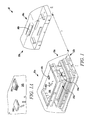
- Fig. 1 is a perspective view of a detector in accordance herewith
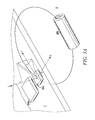
- Fig. 1A is an enlarged view of a portion of the detector of Fig. 1 ;
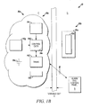
- Fig. 1B is a block diagram of a portion of the detector of Fig. 1 ;
- Fig. 2 is a flow diagram illustrating aspects of processing information obtained from a detector as in Fig. 1 ;
- Fig. 3 is a perspective view of another detector in accordance herewith;
- Fig. 3A illustrates other aspects of the embodiment of Fig. 3 ;
- FIGS. 4A-4D taken together illustrate aspects of another method in accordance herewith.
- Embodiments hereof advantageously utilize a high sensitivity low current draw magnetometer to sense movement of a local, but displaced, magnet.
- one sensor can be used to detect gaps from zero to the large gaps desired.
- signals can be transmitted on two or more alarm loops where a large gap threshold is set for one loop, say a 6" gap, and a small gap threshold will be set for the other loop, say a 1" gap. The installer can decide which loop the respective security control panel will act on. Therefore this invention solves the final installer issue of using one sensor for large or small gap performance with no adjustment required at the sensor.
- the detector can include control circuits implemented, for example with an ASIC or a programmable microcontroller, or programmable processor.
- the circuitry could contain magnetic field thresholds for a low sensitivity reporting loop (loop 1) which would equate to the door / window magnet at a distance of say 1 inch and a high sensitivity reporting loop (loop 2) which would equate to the door/window magnet at a distance of say 6 inches.
- the circuitry could perform the following operations at a frequency sufficient to preclude the ability of an intruder to open a door, gain access and close the door.
- the frequency of operation would be at least 3 times per second to preclude this.
- a significantly higher frequency can be used in a wired sensor, a wireless sensor will use a lower frequency that will insure detection while maximizing battery life.
- the circuitry would monitor the field strength reported by the magnetometer. It would compare the field strength to the high threshold set for loop 1 and the low threshold set for loop 2
- the circuitry will set the status flag for both loops 1 and 2 to normal, indicative of a no alarm state, as the magnet is within the max gap of both loops. If the field strength is below the high threshold set for loop 1 and above the low threshold set for loop 2, the circuitry sets a flag of normal for a normal loop 2 state and sends a transmission to the alarm system control panel identifying that loop 1 is in alarm and loop 2 is normal. If the field strength is below the threshold set for both loops, the circuitry sends a transmission to the panel identifying that both loop 1 and loop 2 are in alarm.
- a high sensitivity 3-axis magnetometer and control circuitry can be incorporated into a door frame mountable detector assembly, and, a randomly oriented magnet can be incorporated in a door mountable magnet housing.
- the 3-axis magnetometer will output the sensed X, Y, and Z components of the magnetic flux vector present at the sensor. The majority of this vector is produced by the randomly oriented magnet.
- the circuitry will learn the magnitude and direction (+ or -) of each of the magnetic vector components when the door is closed with magnet in place. The control circuitry will then assign a factory loaded tolerance band to each of these vector component values. If the vector value goes outside of the allowable band, the detector assembly issues an alarm.
- the detector assembly can be field programmable to work with a unique magnet assembly. At least 8 different magnet assemblies are needed to comply with these requirements. It is a particular advantage of this embodiment that one small and inexpensive magnet can be configured to produce an infinite number of different magnet assemblies. This result can be effected by changing the orientation of the magnet in each magnet assembly.
- the magnet can be enclosed in a plastic sphere and placed in a housing which contains a recess to locate the sphere.
- the finished sphere assemblies are tossed into a bin in no given orientation.
- the spheres are dropped into recesses of the magnet housing component referred to as the "carrier" in the attachment.
- the resulting orientation of the magnets and spheres will be completely random. This now achieves the EN criteria for a minimum of 8 different codes and actually results in an infinite number of unique magnet assemblies.
- the sensor Since the sensor will "learn" the unique magnetic vector of each magnet assembly when installed, the installer will not be confined to tight gap tolerances during installation. Any foreign magnet that is brought into the vicinity of the sensor will force at least one of the magnetic field vector components (X, Y, or Z) to move beyond its' permitted boundaries resulting in an alarm.
- the detector assembly After the detector assembly and magnet assembly have been installed, for example on a respective door and frame, and with the door closed, the detector assembly will "learn" the magnetic field vector present at the magnetometer in this secure configuration. Insuring that the door is closed, the installer would connect the wires to the panel and apply power.
- the sensor will verify the magnetometer output on at least one axis (X, Y, or Z) exceeds 750 milligauss and the values seen on all axes are stable. The sensor will then record the values for X, Y and Z and establish the alarm points for each axis.
- the sensor will issue an alarm signal by opening the Alarm Relay.
- the sensor will insure that the door magnet is present by verifying that at least one magnetic vector component value exceeds 750 milligauss. This is to insure that the sensor is not being set to the earth's magnetic field without the door magnet present.
- the Earth's magnetic field vector has a stronger vertical component than horizontal component in all of North America and Europe.
- the intensity of the Earth's magnetic field varies significantly around the world. We must insure that this invention will work everywhere.
- the Earth's maximum magnetic field intensity on the surface of the Earth in an inhabited location occurs in Southern Australia in Hobart. The intensity is 620 milligauss with the vertical component being 592 milligauss and the horizontal component being 186 milligauss.
- the absolute maximum occurs at a location on the coast of Antarctica nearest Australia with a value of 660 milligauss.
- Figs. 1-1B illustrate aspects of a detector 10.
- Detector 10 includes a detector assembly 10a and a magnet assembly 10b.
- Assembly 10a can be mounted, for example on a fixed object, such as a door or window frame F.
- Assembly 10b can be mounted on a movable member, such as a door or window D. Other arrangements are within the scope hereof.
- Assembly 10a can include a hollow housing 12a, which is closed by a base 12b.
- the assembly 10a is energized by batteries 14a carried by base 12b.
- the batteries are contained by battery terminals that are mounted to the printed circuit board 14b (PCB), the PCB is mounted in the housing 12a and the base prohibits motion of the batteries once the base is installed.
- the printed circuit board 14b carries a magnetometer 14c which is coupled to control circuits which can include a programmable processor, or controller, 14d along with executable control programs or software 14e, best seen in Fig. 1B .
- the housing 12a can also carry a wireless transceiver 14f coupled to the control circuits 14d for communicating wirelessly via a medium M with a displaced alarm system control panel S.
- An optional tamper switch 14g can be coupled to the control circuits 14d.
- the magnetometer 14c can be implemented with one of a variety of commercially available, low cost integrated circuits such as a single axis chip MMLP57H from MultiDimension Technology Co., Ltd., a multi-axis chip HMC5983 from Honeywell International Inc., or a multi-axis chip MAG3110 from Freescale, all without limitation.
- a variety of programmable processors could be used with any of the above noted sensors without departing from the spirit and scope hereof.
- Assembly 10b includes a housing 16a which carries a selectively oriented magnet 16b.
- magnet 16b is illustrated in Fig. 1 oriented perpendicular to the gap direction.
- the magnet 16b can exhibit a variety of shapes, and orientations, relative to the magnetometer, without departing from the spirit and scope hereof.
- assembly 10a transmits determinations, based on real-time signals from magnetometer 14c, to the system S indicative of the door, or window, D moving from a closed position, relative to frame F to an open position.
- magnetometer 14c can be implemented as the above noted single axis chip MMLP57H. It will also be understood that other arrangements come within the spirit and scope hereof.
- processing circuitry 14d can make a determination as to gap magnitude and transmit an indicium thereof to the system D.
- Fig. 2 illustrates dual loop exemplary processing 100.
- the circuitry 14d could perform the operations illustrated in Fig. 2 about 3 or more times per second.
- the circuitry 14d would monitor the field strength reported by the magnetometer 14c. It would compare the field strength to the threshold set for loop 2, as at 104, and if the signal exceeds that threshold, it would evaluate the signal relative to the threshold set for loop 1, as at 106. If below the loop 1 threshold, a loop 1 alarm could be transmitted and the loop 2 flag could be set to secure as at 108. Alternately, if the signal is below the loop 2 threshold, as at 104, alarms could be set on both loops 1, 2, as at 110.
- Figs. 3 , 3A and 4A-4D illustrate aspects of a high security detector 30.
- Detector 30 includes a detector assembly 30a and a magnet assembly 30b.
- Assembly 30a can be mounted, for example, on a door frame F.
- Assembly 30b can be mounted on a movable object, such as a door D.
- Assembly 30a can include a hollow housing 32a.
- the assembly 30a is energized via cables C which couple the detector 30 to the system S.
- the assembly 30a can be energized by batteries.
- a printed circuit board 34b carries a magnetometer 34c which is coupled to control circuits 34d which can include a programmable processor, or controller, along with executable control programs or software such as seen in Fig. 1B .
- the housing 32a can also carry cable drive/receive circuits including end-of-line resistors and varistors 34-1, 34-2 coupled to the control circuits.
- a tamper switch 34g can be coupled to the control circuits 34d.
- Fig. 3A illustrates various advantageous aspects of using a multi-axis magnetometer in combination with a randomly oriented magnet.
- Figs. 4A-4D illustrates aspects of a manufacturing method 200 which produces randomly oriented magnets 36b usable to provide security in the detector 30.
- Fig. 4A illustrates assembling a magnet 36b in a spherical housing 40a, b.
- a plurality of carriers C1...Cn can carry a plurality of housings 40-I with each housing including a randomly oriented magnet, such as magnet 36b.
- each of the carriers Ci with an associated magnet, such as 40-I can be inserted into a housing 36a.
- the respective housings, carriers and magnets can be potted with an epoxy, or other, compound, as in Fig. 4D , to fix the orientation of the respective magnet, such as 40-i.
- a boss 42 can be added to each respective sphere, such as 40-I to preclude the respective magnet, such as 36b, from ever being aligned with the X, Y, or Z axis of the respective magnetometer, such as 34c.
Landscapes
- Physics & Mathematics (AREA)
- General Physics & Mathematics (AREA)
- Business, Economics & Management (AREA)
- Emergency Management (AREA)
- Burglar Alarm Systems (AREA)
Abstract
Description
- The application pertains to position detectors. More particularly, the application pertains to detectors usable to detect displacement of doors and windows from closed positions to partly, or fully open positions and to produce indicators thereof which can be transmitted to regional monitoring systems.
- Regional security monitoring systems often contain detectors that monitor the open/closed state of doors and windows. The vast majority of known non-contact door and window detectors consist of a magnet mounted on the door or window and a reed switch in a housing mounted on the door frame or window frame. This type of detector is generically referred to as a "magnetic contact". The problem with the magnet/reed switch combination is that the sensing range (gap between the pair) is limited to ½ to 1 inch for standard magnetic contacts and up to 3 inches if the design contains very large/expensive magnets on the door and/or a "helper magnet" in the sensor housing. These gaps only apply on non-ferromagnetic materials (wood). The gap for most sensors is reduced to ½ that noted when mounted on ferromagnetic materials such as steel. This means the maximum gap available on steel in the industry today is on the order of 1.5 inches.
- Users would like to achieve a gaps on steel greater than 1.5 inches and up to 4 inches. They want to install door detectors on perimeter fences, sheds and pool gates. These doors have large gaps and the doors and frames are often made of steel. Also, as these are typically outdoor detectors, the users would like these to be wireless and not require battery replacement for five years.
- Additionally, a given magnetic contact (magnet / reed switch pair) will have a specific distance at which the detector will indicate the door is open. There is no adjustment capability in these units. Therefore, if an installer has some doors and windows that he would like to set to alarm at a small gap and others like pool gates that he would like to set for large gaps, then he must carry two different products. Users would like a door window detector that can be set for small gaps and large gaps with a minimum of field adjustment and preferably no physical adjustment at the sensor.
- High Security (Defeat Resistant) Magnetically Actuated Contacts have been in the Intrusion Security market place for a number of years. These are typically in the form of magnetically balanced contacts where a switch housing contains multiple form C reed switches and multiple magnets. In the absence of the door mounted magnet assembly, each reed switch in the housing is actuated by a corresponding magnet in the housing. When the door mounted magnet assembly which contains multiple magnets comes into proper position, the magnetic field at each reed switches is cancelled out (balanced) allowing each reed to be in the unactuated state. If the door mounted magnet assembly gets too close or too far away, at least one reed switch in the switch housing will actuate causing an alarm. Manufacture of this type of switch is highly labor intensive as the positions of the magnets and reed switches must be massaged due to tolerances to get the "balance" just right. In known products, one of the issues has been that the installer must be very careful to precisely set the gap between the switch housing and the magnet housing. Too small or too large and the switch will go into alarm. Although quite difficult to defeat, one cognizant of the design and armed with an identical door mount magnet assembly does have the possibility of defeating a high security contact. It takes significant practice but it can be done. The high end market, banks, nuclear facilities, military contractors and the military, is asking for a virtually defeat proof contact.
- Most professional security manufacturers strive to have their products meet the requirements set in the standards published by the governing compliance agencies. The requirements for contacts sold in the Americas are published in UL 634. The requirements for contacts sold in Europe are covered in EN50131-2-6. The requirements set for the highest grade or level contacts in each standard are intended to provide sufficient safe-guards against intruders that are assumed to be highly intelligent, highly skilled in the detector design, and have attempted to defeat similar product. Products passing these requirements are intended for use in high security installations such as military and nuclear facilities. In October of 2007, UL published requirements for a higher grade of High Security contact, UL 634
Level 2. The requirements forLevel 2 specify many more and more intricate attacks on the sensor which High Security Contacts on the market at that time could not meet. In September 2008, Europe published requirements for 4 grades of magnetically actuated switches in EN 50131-2-6 withGrade 1 having the least stringent requirements and Grade 4 being the most stringent. The Honeywell 968XTP is certified to the requirements of the second highest grade, Grade 3 but does not meet the requirements of the highest grade, Grade 4. The requirements state that Grade 4 switch products must have a minimum of 8 match-coded-pairs of switches/door magnets where a given switch assembly can only function with one of the at least 8 different magnets. - Using the existing approaches, this would mean a minimum of 8 different SKU's for one model number. Producing a product line with 8 match coded pairs could be extremely labor intensive. In addition, the number of parts for a product that will function singularly with 8 match-coded-pairs would increase significantly to account for the additional magnets and reeds that would be required to satisfy this requirement.
-
Fig. 1 is a perspective view of a detector in accordance herewith; -
Fig. 1A is an enlarged view of a portion of the detector ofFig. 1 ; -
Fig. 1B is a block diagram of a portion of the detector ofFig. 1 ; -
Fig. 2 is a flow diagram illustrating aspects of processing information obtained from a detector as inFig. 1 ; -
Fig. 3 is a perspective view of another detector in accordance herewith; -
Fig. 3A illustrates other aspects of the embodiment ofFig. 3 ; and -
Figs. 4A-4D taken together illustrate aspects of another method in accordance herewith. - While disclosed embodiments can take many different forms, specific embodiments hereof are shown in the drawings and will be described herein in detail with the understanding that the present disclosure is to be considered as an exemplification of the principles hereof, as well as the best mode of practicing same, and is not intended to limit the claims hereof to the specific embodiment illustrated.
- Embodiments hereof advantageously utilize a high sensitivity low current draw magnetometer to sense movement of a local, but displaced, magnet. In one aspect, one sensor can be used to detect gaps from zero to the large gaps desired. In a further aspect, signals can be transmitted on two or more alarm loops where a large gap threshold is set for one loop, say a 6" gap, and a small gap threshold will be set for the other loop, say a 1" gap. The installer can decide which loop the respective security control panel will act on. Therefore this invention solves the final installer issue of using one sensor for large or small gap performance with no adjustment required at the sensor.
- In another aspect, the detector can include control circuits implemented, for example with an ASIC or a programmable microcontroller, or programmable processor. The circuitry could contain magnetic field thresholds for a low sensitivity reporting loop (loop 1) which would equate to the door / window magnet at a distance of say 1 inch and a high sensitivity reporting loop (loop 2) which would equate to the door/window magnet at a distance of say 6 inches.
- In embodiments hereof, the circuitry could perform the following operations at a frequency sufficient to preclude the ability of an intruder to open a door, gain access and close the door. The frequency of operation would be at least 3 times per second to preclude this. Although a significantly higher frequency can be used in a wired sensor, a wireless sensor will use a lower frequency that will insure detection while maximizing battery life. The circuitry would monitor the field strength reported by the magnetometer. It would compare the field strength to the high threshold set for
loop 1 and the low threshold set forloop 2 - If the field strength is above the thresholds set for both
loop 1 andloop 2, the circuitry will set the status flag for bothloops loop 1 and above the low threshold set forloop 2, the circuitry sets a flag of normal for anormal loop 2 state and sends a transmission to the alarm system control panel identifying thatloop 1 is in alarm andloop 2 is normal. If the field strength is below the threshold set for both loops, the circuitry sends a transmission to the panel identifying that bothloop 1 andloop 2 are in alarm. - In another embodiment, a high sensitivity 3-axis magnetometer and control circuitry can be incorporated into a door frame mountable detector assembly, and, a randomly oriented magnet can be incorporated in a door mountable magnet housing. The 3-axis magnetometer will output the sensed X, Y, and Z components of the magnetic flux vector present at the sensor. The majority of this vector is produced by the randomly oriented magnet.
- During installation, the circuitry will learn the magnitude and direction (+ or -) of each of the magnetic vector components when the door is closed with magnet in place. The control circuitry will then assign a factory loaded tolerance band to each of these vector component values. If the vector value goes outside of the allowable band, the detector assembly issues an alarm.
- To meet the EN Grade 4 requirements, the detector assembly can be field programmable to work with a unique magnet assembly. At least 8 different magnet assemblies are needed to comply with these requirements. It is a particular advantage of this embodiment that one small and inexpensive magnet can be configured to produce an infinite number of different magnet assemblies. This result can be effected by changing the orientation of the magnet in each magnet assembly.
- The magnet can be enclosed in a plastic sphere and placed in a housing which contains a recess to locate the sphere. During assembly of the magnet and spherical shell, the finished sphere assemblies are tossed into a bin in no given orientation. At the next assembly station the spheres are dropped into recesses of the magnet housing component referred to as the "carrier" in the attachment. The resulting orientation of the magnets and spheres will be completely random. This now achieves the EN criteria for a minimum of 8 different codes and actually results in an infinite number of unique magnet assemblies.
- Since the sensor will "learn" the unique magnetic vector of each magnet assembly when installed, the installer will not be confined to tight gap tolerances during installation. Any foreign magnet that is brought into the vicinity of the sensor will force at least one of the magnetic field vector components (X, Y, or Z) to move beyond its' permitted boundaries resulting in an alarm.
- It would be extremely difficult for a person practiced in the art of defeating balanced magnetic switches to defeat this invention if he had an identical magnet assembly. However, since no two magnet assemblies will be identical, this person has no chance of defeating this invention. As an additional feature a small boss can be formed on or attached to the sphere, for example 1 mm in diameter by 1 mm tall, in-line with the magnet axis. This would preclude the magnet from ever being directly aligned with one of magnetometer axes X, Y, or Z therefore insuring that the magnetic vector has significant components on at least 2 of the 3 magnetometer sensing axes.
- After the detector assembly and magnet assembly have been installed, for example on a respective door and frame, and with the door closed, the detector assembly will "learn" the magnetic field vector present at the magnetometer in this secure configuration. Insuring that the door is closed, the installer would connect the wires to the panel and apply power. The sensor will verify the magnetometer output on at least one axis (X, Y, or Z) exceeds 750 milligauss and the values seen on all axes are stable. The sensor will then record the values for X, Y and Z and establish the alarm points for each axis.
- If the value for any axis exceeds its' alarm points, the sensor will issue an alarm signal by opening the Alarm Relay. On power-up, the sensor will insure that the door magnet is present by verifying that at least one magnetic vector component value exceeds 750 milligauss. This is to insure that the sensor is not being set to the earth's magnetic field without the door magnet present.
- Unknown to many, the Earth's magnetic field vector has a stronger vertical component than horizontal component in all of North America and Europe. The intensity of the Earth's magnetic field varies significantly around the world. We must insure that this invention will work everywhere. The Earth's maximum magnetic field intensity on the surface of the Earth in an inhabited location occurs in Southern Australia in Hobart. The intensity is 620 milligauss with the vertical component being 592 milligauss and the horizontal component being 186 milligauss. The absolute maximum occurs at a location on the coast of Antarctica nearest Australia with a value of 660 milligauss. By setting the sensor minimum to 750 milligauss as a condition to record the door closed values, we insure that the sensor is not errantly setting the values for the Earth's magnetic field with the door open.
-
Figs. 1-1B illustrate aspects of adetector 10.Detector 10 includes adetector assembly 10a and amagnet assembly 10b.Assembly 10a can be mounted, for example on a fixed object, such as a door or windowframe F. Assembly 10b can be mounted on a movable member, such as a door or window D. Other arrangements are within the scope hereof. -
Assembly 10a can include ahollow housing 12a, which is closed by a base 12b. Theassembly 10a is energized bybatteries 14a carried by base 12b. For example, the batteries are contained by battery terminals that are mounted to the printedcircuit board 14b (PCB), the PCB is mounted in thehousing 12a and the base prohibits motion of the batteries once the base is installed. The printedcircuit board 14b carries amagnetometer 14c which is coupled to control circuits which can include a programmable processor, or controller, 14d along with executable control programs orsoftware 14e, best seen inFig. 1B . - The
housing 12a can also carry awireless transceiver 14f coupled to thecontrol circuits 14d for communicating wirelessly via a medium M with a displaced alarm system control panel S. Anoptional tamper switch 14g can be coupled to thecontrol circuits 14d. - The
magnetometer 14c can be implemented with one of a variety of commercially available, low cost integrated circuits such as a single axis chip MMLP57H from MultiDimension Technology Co., Ltd., a multi-axis chip HMC5983 from Honeywell International Inc., or a multi-axis chip MAG3110 from Freescale, all without limitation. Those of skill will understand that a variety of programmable processors could be used with any of the above noted sensors without departing from the spirit and scope hereof. -
Assembly 10b includes ahousing 16a which carries a selectively oriented magnet 16b. For example, magnet 16b is illustrated inFig. 1 oriented perpendicular to the gap direction. Those of skill will understand that the magnet 16b can exhibit a variety of shapes, and orientations, relative to the magnetometer, without departing from the spirit and scope hereof. - As discussed above,
assembly 10a transmits determinations, based on real-time signals frommagnetometer 14c, to the system S indicative of the door, or window, D moving from a closed position, relative to frame F to an open position. In one aspect,magnetometer 14c can be implemented as the above noted single axis chip MMLP57H. It will also be understood that other arrangements come within the spirit and scope hereof. - Responsive to the signal from
sensor 14c,processing circuitry 14d can make a determination as to gap magnitude and transmit an indicium thereof to the system D.Fig. 2 illustrates dual loop exemplary processing 100. - In embodiments hereof, the
circuitry 14d could perform the operations illustrated inFig. 2 about 3 or more times per second. Thecircuitry 14d would monitor the field strength reported by themagnetometer 14c. It would compare the field strength to the threshold set forloop 2, as at 104, and if the signal exceeds that threshold, it would evaluate the signal relative to the threshold set forloop 1, as at 106. If below theloop 1 threshold, aloop 1 alarm could be transmitted and theloop 2 flag could be set to secure as at 108. Alternately, if the signal is below theloop 2 threshold, as at 104, alarms could be set on bothloops -
Figs. 3 ,3A and4A-4D illustrate aspects of ahigh security detector 30.Detector 30 includes adetector assembly 30a and amagnet assembly 30b.Assembly 30a can be mounted, for example, on a doorframe F. Assembly 30b can be mounted on a movable object, such as a door D. -
Assembly 30a can include ahollow housing 32a. Theassembly 30a is energized via cables C which couple thedetector 30 to the system S. In an alternate embodiment similar to that shown inFigure 1 , theassembly 30a can be energized by batteries. A printedcircuit board 34b carries amagnetometer 34c which is coupled to controlcircuits 34d which can include a programmable processor, or controller, along with executable control programs or software such as seen inFig. 1B . - The
housing 32a can also carry cable drive/receive circuits including end-of-line resistors and varistors 34-1, 34-2 coupled to the control circuits. Atamper switch 34g can be coupled to thecontrol circuits 34d. -
Fig. 3A illustrates various advantageous aspects of using a multi-axis magnetometer in combination with a randomly oriented magnet. With the random orientations, an intruder is faced with trying to duplicate a unique orientation and magnitude which makes detectors, such as thedetector 30, significantly more defeat resistant. -
Figs. 4A-4D illustrates aspects of amanufacturing method 200 which produces randomly orientedmagnets 36b usable to provide security in thedetector 30. AsFig. 4A illustrates assembling amagnet 36b in a spherical housing 40a, b. As illustrated inFig. 4B a plurality of carriers C1...Cn can carry a plurality of housings 40-I with each housing including a randomly oriented magnet, such asmagnet 36b. - As in
fig. 4C , each of the carriers Ci with an associated magnet, such as 40-I can be inserted into ahousing 36a. The respective housings, carriers and magnets can be potted with an epoxy, or other, compound, as inFig. 4D , to fix the orientation of the respective magnet, such as 40-i. - Once potted the orientation of the magnet can not be determined visually. Hence, it makes it very difficult, if not impossible for an intruder to obtain a magnet with the same magnetic orientation as in the respective detector.
- As illustrated in
Fig. 4B-2 , a boss 42 can be added to each respective sphere, such as 40-I to preclude the respective magnet, such as 36b, from ever being aligned with the X, Y, or Z axis of the respective magnetometer, such as 34c. - From the foregoing, it will be observed that numerous variations and modifications may be effected without departing from the spirit and scope of the invention. It is to be understood that no limitation with respect to the specific apparatus illustrated herein is intended or should be inferred. It is, of course, intended to cover by the appended claims all such modifications as fall within the scope of the claims.
- Further, logic flows depicted in the figures do not require the particular order shown, or sequential order, to achieve desirable results. Other steps may be provided, or steps may be eliminated, from the described flows, and other components may be add to, or removed from the described embodiments.
Claims (15)
- A detector comprising a proximity sensor and circuitry having at least two distance sensing thresholds; the circuitry compares a proximity signal, from the sensor, to each of the thresholds and sends a signal indicative of the relationship of the signal to each threshold to a displaced control unit.
- A detector as in claim 1 wherein the sensor is part of an intrusion security system and detects an open or closed position of an element selected from a class which includes at least a door, a window, or a gate.
- A detector as in claim 2 wherein the sensor is a wireless sensor and transmits alarm status on individual reporting loops for each threshold.
- A detector as in claim 2 wherein the sensor is mountable to at least one of a door frame, a window frame, or a fence post and detects a target mountable to one of a door, a window or a gate.
- A detector as in claim 4 wherein the sensor contains a magnetometer and the target contains a permanent magnet.
- A detector as in claim 5 wherein the thresholds for each loop are sets of thresholds wherein the each threshold set accounts for orientation of the magnet providing either positive or negative magnetic flux.
- A detector as in claim 4 wherein the sensor contains a light emitter and light detector and the target is a reflector of light.
- A detector as in claim 7 wherein the light is in the near Infrared spectrum between 800nm and 1.4µm.
- A detector as in claim 4 wherein the sensor contains a capacitive sensing element and the target contains a high capacitance object comprising a metal.
- A proximity sensor to detect the open or closed position of a door, or window as part of an intrusion security system wherein the sensor includes circuitry capable of determining a magnetic flux vector of a proximal magnet on at least two sensing axes.
- A detector as in claim 10 wherein the sensor includes a housing which contains one of a two or three axis magnetometer and detects a magnetic field of an independent magnet located outside of the sensor housing.
- A detector as in claim 11 wherein the sensor includes one of a microcontroller or microprocessor capable of being programmed during installation to learn the magnetic field vector of the associated magnet when mounted and in the selected position.
- A detector as in claim 12 wherein the sensor is mountable to at least one of a door frame, window frame or bank vault and when so mounted, detects the field of a magnet that is mounted to a door, window, or vault door.
- A detector as in claim 12 wherein the microcontroller or microprocessor Includes a tolerance band applied to each axis value of the learned magnetic field vector which if any band limit is exceeded will issue an alarm signal.
- A detector as in claim 12 wherein the sensor comprises circuitry to learn and function with any one of a plurality of proximal magnets which exhibit and function with any one of a plurality of proximal magnets which exhibit differing magnetic field vectors having at least one of varying magnitudes, or varying directions.
Applications Claiming Priority (1)
| Application Number | Priority Date | Filing Date | Title |
|---|---|---|---|
| US13/441,959 US8970373B2 (en) | 2012-04-09 | 2012-04-09 | Large gap door/window, high security, intrusion detectors using magnetometers |
Publications (3)
| Publication Number | Publication Date |
|---|---|
| EP2650848A2 true EP2650848A2 (en) | 2013-10-16 |
| EP2650848A3 EP2650848A3 (en) | 2018-03-07 |
| EP2650848B1 EP2650848B1 (en) | 2023-03-08 |
Family
ID=48044574
Family Applications (1)
| Application Number | Title | Priority Date | Filing Date |
|---|---|---|---|
| EP13160449.8A Active EP2650848B1 (en) | 2012-04-09 | 2013-03-21 | Large gap door/window, high security, intrusion detectors using magnetometers |
Country Status (5)
| Country | Link |
|---|---|
| US (1) | US8970373B2 (en) |
| EP (1) | EP2650848B1 (en) |
| CN (1) | CN103456115B (en) |
| CA (1) | CA2810219C (en) |
| ES (1) | ES2944287T3 (en) |
Cited By (3)
| Publication number | Priority date | Publication date | Assignee | Title |
|---|---|---|---|---|
| WO2016109411A1 (en) * | 2014-12-30 | 2016-07-07 | Google Inc. | Guided installation for a magnetic door opening sensor |
| EP3107077A1 (en) * | 2015-06-18 | 2016-12-21 | Cooper CSA S.r.l. | Anti-intrusion detecting method to be applied to doors or windows and related anti-intrusion system |
| US11280927B2 (en) | 2018-12-31 | 2022-03-22 | Essence Security International (E.S.I.) Ltd. | Magnetic field sensor for an access point |
Families Citing this family (28)
| Publication number | Priority date | Publication date | Assignee | Title |
|---|---|---|---|---|
| US9569942B2 (en) | 2012-09-18 | 2017-02-14 | Vootner Goushe Llc | Sensor system for protection of artworks and other valuable objects |
| US9631920B2 (en) * | 2013-10-16 | 2017-04-25 | Google Inc. | Sensing system for verifying deadbolt engagement |
| CN104504864A (en) * | 2014-11-28 | 2015-04-08 | 常州超音电子有限公司 | Alarm for door fame |
| US9952029B2 (en) * | 2015-04-08 | 2018-04-24 | Google Llc | Guided installation feedback for an opening sensor |
| US9982459B2 (en) | 2015-06-01 | 2018-05-29 | Schlage Lock Company Llc | Door improvements and data mining via accelerometer and magnetometer electronic component |
| US20170098356A1 (en) * | 2015-10-06 | 2017-04-06 | Google Inc. | Opening Sensor with Magnetic Field Detection |
| BE1024049B1 (en) * | 2015-11-11 | 2017-11-08 | Melexis Technologies Nv | MAGNETIC SENSOR |
| US10393554B2 (en) | 2016-02-09 | 2019-08-27 | Sensormatic Electronics, LLC | Security system having a magnetic displacement sensor system and analytics system |
| US9953503B2 (en) | 2016-02-23 | 2018-04-24 | Honeywell International Inc. | Door and window contact systems and methods that include MEMS accelerometers and MEMS magnetometers |
| CN106204989B (en) * | 2016-07-20 | 2019-03-12 | 陕西哥莱信息科技有限公司 | A kind of smart window intruding detection system and method |
| GB2554394A (en) * | 2016-09-23 | 2018-04-04 | Laporta Giovanni | Improvements to windows / doors |
| CN111226265B (en) * | 2017-10-10 | 2021-10-15 | 阿勒特系统公司 | Anti-theft system and method with magnetic field detection |
| CN107993325A (en) * | 2017-12-18 | 2018-05-04 | 重庆多邦科技股份有限公司 | A kind of access control system, method and apparatus |
| US10643440B2 (en) | 2018-01-03 | 2020-05-05 | Ademco Inc. | Door/window sensor |
| USD850946S1 (en) | 2018-02-01 | 2019-06-11 | Tyco Fire & Security Gmbh | Position detector |
| US10718147B2 (en) | 2018-04-06 | 2020-07-21 | Tyco Fire & Security Gmbh | Optical displacement detector with adjustable pattern direction |
| US10755554B2 (en) | 2018-09-28 | 2020-08-25 | Nortek Security & Control Llc | Vector magnetic tamper detection for sensors |
| WO2020222722A1 (en) * | 2019-05-02 | 2020-11-05 | Антон Валэрийовыч РЭМИЗ | Alarm device |
| GB202008826D0 (en) | 2020-06-10 | 2020-07-22 | Essence Security International Esi Ltd | Sensing device for access point |
| WO2022025776A1 (en) * | 2020-07-30 | 2022-02-03 | Wellington Drive Technologies Limited | Magnetic door position detection apparatus |
| WO2022066470A1 (en) * | 2020-09-25 | 2022-03-31 | ASSA ABLOY Residential Group, Inc. | Door lock with magnetometers |
| CN112258756B (en) * | 2020-10-21 | 2022-07-08 | 苏州市相城数字科技有限公司 | Electrostatic grading protection type enclosure anti-overturning and anti-theft system |
| US11610463B2 (en) * | 2021-05-18 | 2023-03-21 | Comcast Cable Communications, Llc | Sensor arrangement |
| US12223821B1 (en) * | 2021-06-08 | 2025-02-11 | M2 Companies, Inc. | Anti-defeat magnetically actuated proximity sensor |
| USD993000S1 (en) | 2021-12-20 | 2023-07-25 | ASSA ABLOY Residential Group, Inc. | Lock |
| US12291903B2 (en) | 2021-12-20 | 2025-05-06 | ASSA ABLOY Residential Group, Inc. | Deadbolt lock system |
| USD992999S1 (en) | 2021-12-20 | 2023-07-25 | ASSA ABLOY Residential Group, Inc. | Lock |
| USD1061215S1 (en) | 2023-04-20 | 2025-02-11 | Master Lock Company Llc | Door lock |
Family Cites Families (25)
| Publication number | Priority date | Publication date | Assignee | Title |
|---|---|---|---|---|
| US3305805A (en) | 1963-11-14 | 1967-02-21 | Tann David | Proximity switch |
| US3745553A (en) | 1971-12-06 | 1973-07-10 | Honeywell Inc | Single source several sensor security system |
| CA1145008A (en) | 1980-01-22 | 1983-04-19 | Ezequiel Mejia | Intrusion detecting switch |
| US4507654A (en) | 1981-10-30 | 1985-03-26 | A. R. F. Products | Security system with infrared optical position detector |
| US4812674A (en) | 1985-05-20 | 1989-03-14 | Square D Company | Safety gate limit switch using Hall effect transducer |
| US5155469A (en) | 1989-12-21 | 1992-10-13 | Honeywell, Inc. | Wireless alarm system |
| US5004999A (en) | 1989-12-21 | 1991-04-02 | Honeywell, Inc. | Extended RF range alarm system |
| NL9200283A (en) * | 1992-02-17 | 1993-09-16 | Aritech Bv | MONITORING SYSTEM. |
| US5534849A (en) * | 1993-08-11 | 1996-07-09 | Sentrol, Inc. | Time multiplexed, false alarm resistant magnetically actuated security system |
| US5654686A (en) | 1995-07-26 | 1997-08-05 | Prince Corporation | Electronic vehicle theft detection system employing a magnetic field sensor |
| US5633626A (en) * | 1995-08-29 | 1997-05-27 | The United States Of America As Represented By The United States Department Of Energy | Self-testing security sensor for monitoring closure of vault doors and the like |
| US6784796B2 (en) | 1999-12-17 | 2004-08-31 | The Regents Of The University Of Califronia | Magnetic vector field tag and seal |
| US6310549B1 (en) | 2000-08-29 | 2001-10-30 | Digitech International | Wireless security system |
| US6963281B2 (en) | 2001-09-14 | 2005-11-08 | Honeywell International Inc. | Tamper resistant magnetic contact apparatus for security systems |
| US6472993B1 (en) * | 2001-10-16 | 2002-10-29 | Pittway Corp. | Singular housing window or door intrusion detector using earth magnetic field sensor |
| US7120795B2 (en) | 2002-04-03 | 2006-10-10 | Honeywell International, Inc. | Security system with serial number coding and methods therefor |
| US7356429B2 (en) | 2004-07-15 | 2008-04-08 | Honeywell International, Inc. | Method for remotely changing the sensitivity of a wireless sensor |
| US7187282B2 (en) * | 2004-09-09 | 2007-03-06 | Invisa, Inc | Digital capacitive sensing device for security and safety applications |
| US7986232B2 (en) | 2006-08-03 | 2011-07-26 | Tyco Safety Products Canada Ltd. | Method and apparatus for using an infrared reflectivity sensor in a security system |
| US7663483B2 (en) * | 2006-12-16 | 2010-02-16 | Roc2Loc, Inc. | Methods and apparatus for security device portal sensing |
| CN101558433A (en) * | 2006-12-16 | 2009-10-14 | 奎克斯编码有限责任公司 | Methods and apparatus for security device portal sensing |
| GB0706702D0 (en) * | 2007-04-05 | 2007-05-16 | Gunton Bruce S | Proximity sensing |
| US20100219951A1 (en) * | 2009-03-02 | 2010-09-02 | Hector Sosa | Magnetic field based alarm system |
| US8258777B2 (en) * | 2009-09-04 | 2012-09-04 | Weihua Chen | Inductive proximity sensor |
| US8981796B2 (en) * | 2010-04-30 | 2015-03-17 | Cynetic Designs Ltd. | Wireless method and apparatus for detecting damage in ceramic body armor |
-
2012
- 2012-04-09 US US13/441,959 patent/US8970373B2/en active Active
-
2013
- 2013-03-21 ES ES13160449T patent/ES2944287T3/en active Active
- 2013-03-21 EP EP13160449.8A patent/EP2650848B1/en active Active
- 2013-03-22 CA CA2810219A patent/CA2810219C/en not_active Expired - Fee Related
- 2013-04-08 CN CN201310119101.6A patent/CN103456115B/en not_active Expired - Fee Related
Non-Patent Citations (1)
| Title |
|---|
| None |
Cited By (7)
| Publication number | Priority date | Publication date | Assignee | Title |
|---|---|---|---|---|
| WO2016109411A1 (en) * | 2014-12-30 | 2016-07-07 | Google Inc. | Guided installation for a magnetic door opening sensor |
| US9523567B2 (en) | 2014-12-30 | 2016-12-20 | Google Inc. | Guided installation for an opening sensor |
| US9830785B2 (en) | 2014-12-30 | 2017-11-28 | Google Llc | Guided installation for an opening sensor |
| US10074248B2 (en) | 2014-12-30 | 2018-09-11 | Google Llc | Guided installation for an opening sensor |
| EP3107077A1 (en) * | 2015-06-18 | 2016-12-21 | Cooper CSA S.r.l. | Anti-intrusion detecting method to be applied to doors or windows and related anti-intrusion system |
| US11280927B2 (en) | 2018-12-31 | 2022-03-22 | Essence Security International (E.S.I.) Ltd. | Magnetic field sensor for an access point |
| US11561316B2 (en) | 2018-12-31 | 2023-01-24 | Essence Security International (E.S.I.) Ltd. | Magnetic field sensor for an access point |
Also Published As
| Publication number | Publication date |
|---|---|
| CA2810219C (en) | 2019-10-22 |
| EP2650848A3 (en) | 2018-03-07 |
| US20130265162A1 (en) | 2013-10-10 |
| CN103456115B (en) | 2018-07-17 |
| ES2944287T3 (en) | 2023-06-20 |
| US8970373B2 (en) | 2015-03-03 |
| CN103456115A (en) | 2013-12-18 |
| CA2810219A1 (en) | 2013-10-09 |
| EP2650848B1 (en) | 2023-03-08 |
Similar Documents
| Publication | Publication Date | Title |
|---|---|---|
| CA2810219C (en) | Large gap door/window, high security, intrusion detectors using magnetometers | |
| US20030052780A1 (en) | Tamper resistant magnetic contact apparatus for security systems | |
| US5668533A (en) | High security balanced-type, magnetically-actuated proximity switch system | |
| US6882275B2 (en) | Microsystem using magnetometer and inclinometer for anti-theft protection of valuables | |
| US10488464B2 (en) | Magnetic sensor circuit for security sensing | |
| US8648720B2 (en) | High security burglar alarm device | |
| WO2008049190A1 (en) | Method and apparatus for magnetically activated radio or infrared identification system | |
| EP2393071B1 (en) | Peripheral device that connects to home alarm systems and serves the global protection of an opening through magnetic switches and motion sensors | |
| US4945340A (en) | Tamper-resistant magnetic security system | |
| US9947189B2 (en) | Home automation device for monitoring the movement of a swinging wing and method for enhancing the reliability of such a device | |
| CA2942419C (en) | A position monitoring device | |
| US9685289B1 (en) | Wireless alarm switch assembly | |
| US8847580B1 (en) | Tamperproof magnetic proximity sensor | |
| RU170689U1 (en) | MAGNETIC CONTACT ALARM SYSTEM | |
| JP3749447B2 (en) | Game machine fraud prevention device | |
| US6348861B1 (en) | Binary multi-code combination sensor | |
| AU2016100138A4 (en) | Swimmer Supervision System | |
| EP3107077B1 (en) | Anti-intrusion detecting method to be applied to doors or windows and related anti-intrusion system | |
| EP0253954B1 (en) | Sensing the open and/or closed condition of valves | |
| EP1266245B1 (en) | Anti-theft device for buildings | |
| EP3458164A1 (en) | Fire extinguisher monitoring system and method | |
| KR20240000833A (en) | Weather filter mounted on the master controller memory server of machine learning based perimeter intrusion detection sensor system | |
| US5844481A (en) | Intrusion detector for security systems | |
| CN210091323U (en) | A magnetic induction position monitoring device | |
| CN107369280A (en) | A kind of door magnetism device |
Legal Events
| Date | Code | Title | Description |
|---|---|---|---|
| PUAI | Public reference made under article 153(3) epc to a published international application that has entered the european phase |
Free format text: ORIGINAL CODE: 0009012 |
|
| 17P | Request for examination filed |
Effective date: 20130321 |
|
| AK | Designated contracting states |
Kind code of ref document: A2 Designated state(s): AL AT BE BG CH CY CZ DE DK EE ES FI FR GB GR HR HU IE IS IT LI LT LU LV MC MK MT NL NO PL PT RO RS SE SI SK SM TR |
|
| AX | Request for extension of the european patent |
Extension state: BA ME |
|
| RAP1 | Party data changed (applicant data changed or rights of an application transferred) |
Owner name: HONEYWELL INTERNATIONAL INC. |
|
| RIC1 | Information provided on ipc code assigned before grant |
Ipc: G08B 13/08 20060101AFI20171025BHEP |
|
| PUAL | Search report despatched |
Free format text: ORIGINAL CODE: 0009013 |
|
| STAA | Information on the status of an ep patent application or granted ep patent |
Free format text: STATUS: EXAMINATION IS IN PROGRESS |
|
| AK | Designated contracting states |
Kind code of ref document: A3 Designated state(s): AL AT BE BG CH CY CZ DE DK EE ES FI FR GB GR HR HU IE IS IT LI LT LU LV MC MK MT NL NO PL PT RO RS SE SI SK SM TR |
|
| AX | Request for extension of the european patent |
Extension state: BA ME |
|
| RIC1 | Information provided on ipc code assigned before grant |
Ipc: G08B 13/08 20060101AFI20180201BHEP |
|
| 17Q | First examination report despatched |
Effective date: 20180221 |
|
| GRAP | Despatch of communication of intention to grant a patent |
Free format text: ORIGINAL CODE: EPIDOSNIGR1 |
|
| STAA | Information on the status of an ep patent application or granted ep patent |
Free format text: STATUS: GRANT OF PATENT IS INTENDED |
|
| INTG | Intention to grant announced |
Effective date: 20210325 |
|
| RAP1 | Party data changed (applicant data changed or rights of an application transferred) |
Owner name: ADEMCO INC. |
|
| GRAJ | Information related to disapproval of communication of intention to grant by the applicant or resumption of examination proceedings by the epo deleted |
Free format text: ORIGINAL CODE: EPIDOSDIGR1 |
|
| STAA | Information on the status of an ep patent application or granted ep patent |
Free format text: STATUS: EXAMINATION IS IN PROGRESS |
|
| INTC | Intention to grant announced (deleted) | ||
| GRAP | Despatch of communication of intention to grant a patent |
Free format text: ORIGINAL CODE: EPIDOSNIGR1 |
|
| STAA | Information on the status of an ep patent application or granted ep patent |
Free format text: STATUS: GRANT OF PATENT IS INTENDED |
|
| INTG | Intention to grant announced |
Effective date: 20220329 |
|
| GRAJ | Information related to disapproval of communication of intention to grant by the applicant or resumption of examination proceedings by the epo deleted |
Free format text: ORIGINAL CODE: EPIDOSDIGR1 |
|
| STAA | Information on the status of an ep patent application or granted ep patent |
Free format text: STATUS: EXAMINATION IS IN PROGRESS |
|
| INTC | Intention to grant announced (deleted) | ||
| GRAP | Despatch of communication of intention to grant a patent |
Free format text: ORIGINAL CODE: EPIDOSNIGR1 |
|
| STAA | Information on the status of an ep patent application or granted ep patent |
Free format text: STATUS: GRANT OF PATENT IS INTENDED |
|
| INTG | Intention to grant announced |
Effective date: 20220922 |
|
| GRAS | Grant fee paid |
Free format text: ORIGINAL CODE: EPIDOSNIGR3 |
|
| GRAA | (expected) grant |
Free format text: ORIGINAL CODE: 0009210 |
|
| STAA | Information on the status of an ep patent application or granted ep patent |
Free format text: STATUS: THE PATENT HAS BEEN GRANTED |
|
| AK | Designated contracting states |
Kind code of ref document: B1 Designated state(s): AL AT BE BG CH CY CZ DE DK EE ES FI FR GB GR HR HU IE IS IT LI LT LU LV MC MK MT NL NO PL PT RO RS SE SI SK SM TR |
|
| REG | Reference to a national code |
Ref country code: GB Ref legal event code: FG4D |
|
| REG | Reference to a national code |
Ref country code: CH Ref legal event code: EP Ref country code: AT Ref legal event code: REF Ref document number: 1553117 Country of ref document: AT Kind code of ref document: T Effective date: 20230315 |
|
| REG | Reference to a national code |
Ref country code: DE Ref legal event code: R096 Ref document number: 602013083405 Country of ref document: DE |
|
| REG | Reference to a national code |
Ref country code: IE Ref legal event code: FG4D |
|
| REG | Reference to a national code |
Ref country code: SE Ref legal event code: TRGR |
|
| REG | Reference to a national code |
Ref country code: ES Ref legal event code: FG2A Ref document number: 2944287 Country of ref document: ES Kind code of ref document: T3 Effective date: 20230620 |
|
| REG | Reference to a national code |
Ref country code: LT Ref legal event code: MG9D |
|
| P01 | Opt-out of the competence of the unified patent court (upc) registered |
Effective date: 20230601 |
|
| REG | Reference to a national code |
Ref country code: NL Ref legal event code: MP Effective date: 20230308 |
|
| PG25 | Lapsed in a contracting state [announced via postgrant information from national office to epo] |
Ref country code: RS Free format text: LAPSE BECAUSE OF FAILURE TO SUBMIT A TRANSLATION OF THE DESCRIPTION OR TO PAY THE FEE WITHIN THE PRESCRIBED TIME-LIMIT Effective date: 20230308 Ref country code: NO Free format text: LAPSE BECAUSE OF FAILURE TO SUBMIT A TRANSLATION OF THE DESCRIPTION OR TO PAY THE FEE WITHIN THE PRESCRIBED TIME-LIMIT Effective date: 20230608 Ref country code: LV Free format text: LAPSE BECAUSE OF FAILURE TO SUBMIT A TRANSLATION OF THE DESCRIPTION OR TO PAY THE FEE WITHIN THE PRESCRIBED TIME-LIMIT Effective date: 20230308 Ref country code: LT Free format text: LAPSE BECAUSE OF FAILURE TO SUBMIT A TRANSLATION OF THE DESCRIPTION OR TO PAY THE FEE WITHIN THE PRESCRIBED TIME-LIMIT Effective date: 20230308 Ref country code: HR Free format text: LAPSE BECAUSE OF FAILURE TO SUBMIT A TRANSLATION OF THE DESCRIPTION OR TO PAY THE FEE WITHIN THE PRESCRIBED TIME-LIMIT Effective date: 20230308 |
|
| REG | Reference to a national code |
Ref country code: AT Ref legal event code: MK05 Ref document number: 1553117 Country of ref document: AT Kind code of ref document: T Effective date: 20230308 |
|
| PG25 | Lapsed in a contracting state [announced via postgrant information from national office to epo] |
Ref country code: NL Free format text: LAPSE BECAUSE OF FAILURE TO SUBMIT A TRANSLATION OF THE DESCRIPTION OR TO PAY THE FEE WITHIN THE PRESCRIBED TIME-LIMIT Effective date: 20230308 Ref country code: GR Free format text: LAPSE BECAUSE OF FAILURE TO SUBMIT A TRANSLATION OF THE DESCRIPTION OR TO PAY THE FEE WITHIN THE PRESCRIBED TIME-LIMIT Effective date: 20230609 Ref country code: FI Free format text: LAPSE BECAUSE OF FAILURE TO SUBMIT A TRANSLATION OF THE DESCRIPTION OR TO PAY THE FEE WITHIN THE PRESCRIBED TIME-LIMIT Effective date: 20230308 |
|
| PG25 | Lapsed in a contracting state [announced via postgrant information from national office to epo] |
Ref country code: SM Free format text: LAPSE BECAUSE OF FAILURE TO SUBMIT A TRANSLATION OF THE DESCRIPTION OR TO PAY THE FEE WITHIN THE PRESCRIBED TIME-LIMIT Effective date: 20230308 Ref country code: RO Free format text: LAPSE BECAUSE OF FAILURE TO SUBMIT A TRANSLATION OF THE DESCRIPTION OR TO PAY THE FEE WITHIN THE PRESCRIBED TIME-LIMIT Effective date: 20230308 Ref country code: PT Free format text: LAPSE BECAUSE OF FAILURE TO SUBMIT A TRANSLATION OF THE DESCRIPTION OR TO PAY THE FEE WITHIN THE PRESCRIBED TIME-LIMIT Effective date: 20230710 Ref country code: EE Free format text: LAPSE BECAUSE OF FAILURE TO SUBMIT A TRANSLATION OF THE DESCRIPTION OR TO PAY THE FEE WITHIN THE PRESCRIBED TIME-LIMIT Effective date: 20230308 Ref country code: CZ Free format text: LAPSE BECAUSE OF FAILURE TO SUBMIT A TRANSLATION OF THE DESCRIPTION OR TO PAY THE FEE WITHIN THE PRESCRIBED TIME-LIMIT Effective date: 20230308 Ref country code: AT Free format text: LAPSE BECAUSE OF FAILURE TO SUBMIT A TRANSLATION OF THE DESCRIPTION OR TO PAY THE FEE WITHIN THE PRESCRIBED TIME-LIMIT Effective date: 20230308 |
|
| REG | Reference to a national code |
Ref country code: CH Ref legal event code: PL |
|
| PG25 | Lapsed in a contracting state [announced via postgrant information from national office to epo] |
Ref country code: SK Free format text: LAPSE BECAUSE OF FAILURE TO SUBMIT A TRANSLATION OF THE DESCRIPTION OR TO PAY THE FEE WITHIN THE PRESCRIBED TIME-LIMIT Effective date: 20230308 Ref country code: PL Free format text: LAPSE BECAUSE OF FAILURE TO SUBMIT A TRANSLATION OF THE DESCRIPTION OR TO PAY THE FEE WITHIN THE PRESCRIBED TIME-LIMIT Effective date: 20230308 Ref country code: IS Free format text: LAPSE BECAUSE OF FAILURE TO SUBMIT A TRANSLATION OF THE DESCRIPTION OR TO PAY THE FEE WITHIN THE PRESCRIBED TIME-LIMIT Effective date: 20230708 |
|
| REG | Reference to a national code |
Ref country code: BE Ref legal event code: MM Effective date: 20230331 |
|
| REG | Reference to a national code |
Ref country code: DE Ref legal event code: R097 Ref document number: 602013083405 Country of ref document: DE |
|
| PG25 | Lapsed in a contracting state [announced via postgrant information from national office to epo] |
Ref country code: LU Free format text: LAPSE BECAUSE OF NON-PAYMENT OF DUE FEES Effective date: 20230321 |
|
| PLBE | No opposition filed within time limit |
Free format text: ORIGINAL CODE: 0009261 |
|
| STAA | Information on the status of an ep patent application or granted ep patent |
Free format text: STATUS: NO OPPOSITION FILED WITHIN TIME LIMIT |
|
| PG25 | Lapsed in a contracting state [announced via postgrant information from national office to epo] |
Ref country code: MC Free format text: LAPSE BECAUSE OF FAILURE TO SUBMIT A TRANSLATION OF THE DESCRIPTION OR TO PAY THE FEE WITHIN THE PRESCRIBED TIME-LIMIT Effective date: 20230308 |
|
| REG | Reference to a national code |
Ref country code: IE Ref legal event code: MM4A |
|
| PG25 | Lapsed in a contracting state [announced via postgrant information from national office to epo] |
Ref country code: SI Free format text: LAPSE BECAUSE OF FAILURE TO SUBMIT A TRANSLATION OF THE DESCRIPTION OR TO PAY THE FEE WITHIN THE PRESCRIBED TIME-LIMIT Effective date: 20230308 Ref country code: MC Free format text: LAPSE BECAUSE OF FAILURE TO SUBMIT A TRANSLATION OF THE DESCRIPTION OR TO PAY THE FEE WITHIN THE PRESCRIBED TIME-LIMIT Effective date: 20230308 Ref country code: LI Free format text: LAPSE BECAUSE OF NON-PAYMENT OF DUE FEES Effective date: 20230331 Ref country code: IE Free format text: LAPSE BECAUSE OF NON-PAYMENT OF DUE FEES Effective date: 20230321 Ref country code: DK Free format text: LAPSE BECAUSE OF FAILURE TO SUBMIT A TRANSLATION OF THE DESCRIPTION OR TO PAY THE FEE WITHIN THE PRESCRIBED TIME-LIMIT Effective date: 20230308 Ref country code: CH Free format text: LAPSE BECAUSE OF NON-PAYMENT OF DUE FEES Effective date: 20230331 |
|
| 26N | No opposition filed |
Effective date: 20231211 |
|
| PG25 | Lapsed in a contracting state [announced via postgrant information from national office to epo] |
Ref country code: BE Free format text: LAPSE BECAUSE OF NON-PAYMENT OF DUE FEES Effective date: 20230331 |
|
| PG25 | Lapsed in a contracting state [announced via postgrant information from national office to epo] |
Ref country code: IT Free format text: LAPSE BECAUSE OF FAILURE TO SUBMIT A TRANSLATION OF THE DESCRIPTION OR TO PAY THE FEE WITHIN THE PRESCRIBED TIME-LIMIT Effective date: 20230308 |
|
| PG25 | Lapsed in a contracting state [announced via postgrant information from national office to epo] |
Ref country code: BG Free format text: LAPSE BECAUSE OF FAILURE TO SUBMIT A TRANSLATION OF THE DESCRIPTION OR TO PAY THE FEE WITHIN THE PRESCRIBED TIME-LIMIT Effective date: 20230308 |
|
| PG25 | Lapsed in a contracting state [announced via postgrant information from national office to epo] |
Ref country code: BG Free format text: LAPSE BECAUSE OF FAILURE TO SUBMIT A TRANSLATION OF THE DESCRIPTION OR TO PAY THE FEE WITHIN THE PRESCRIBED TIME-LIMIT Effective date: 20230308 |
|
| PGFP | Annual fee paid to national office [announced via postgrant information from national office to epo] |
Ref country code: DE Payment date: 20250428 Year of fee payment: 13 |
|
| PGFP | Annual fee paid to national office [announced via postgrant information from national office to epo] |
Ref country code: ES Payment date: 20250423 Year of fee payment: 13 |
|
| PG25 | Lapsed in a contracting state [announced via postgrant information from national office to epo] |
Ref country code: CY Free format text: LAPSE BECAUSE OF FAILURE TO SUBMIT A TRANSLATION OF THE DESCRIPTION OR TO PAY THE FEE WITHIN THE PRESCRIBED TIME-LIMIT; INVALID AB INITIO Effective date: 20130321 |
|
| REG | Reference to a national code |
Ref country code: DE Ref legal event code: R081 Ref document number: 602013083405 Country of ref document: DE Owner name: RESIDEO LLC, WILMINGTON, US Free format text: FORMER OWNER: ADEMCO INC., GOLDEN VALLEY, MN, US |
|
| PG25 | Lapsed in a contracting state [announced via postgrant information from national office to epo] |
Ref country code: HU Free format text: LAPSE BECAUSE OF FAILURE TO SUBMIT A TRANSLATION OF THE DESCRIPTION OR TO PAY THE FEE WITHIN THE PRESCRIBED TIME-LIMIT; INVALID AB INITIO Effective date: 20130321 |
|
| PG25 | Lapsed in a contracting state [announced via postgrant information from national office to epo] |
Ref country code: TR Free format text: LAPSE BECAUSE OF FAILURE TO SUBMIT A TRANSLATION OF THE DESCRIPTION OR TO PAY THE FEE WITHIN THE PRESCRIBED TIME-LIMIT Effective date: 20230308 |
|
| REG | Reference to a national code |
Ref country code: ES Ref legal event code: PC2A Owner name: RESIDEO LLC Effective date: 20260220 |
|
| PGFP | Annual fee paid to national office [announced via postgrant information from national office to epo] |
Ref country code: SE Payment date: 20260323 Year of fee payment: 14 |
|
| PGFP | Annual fee paid to national office [announced via postgrant information from national office to epo] |
Ref country code: GB Payment date: 20260323 Year of fee payment: 14 |
|
| PGFP | Annual fee paid to national office [announced via postgrant information from national office to epo] |
Ref country code: FR Payment date: 20260323 Year of fee payment: 14 |