EP2650615A1 - Oven for baking food products - Google Patents
Oven for baking food products Download PDFInfo
- Publication number
- EP2650615A1 EP2650615A1 EP12163668.2A EP12163668A EP2650615A1 EP 2650615 A1 EP2650615 A1 EP 2650615A1 EP 12163668 A EP12163668 A EP 12163668A EP 2650615 A1 EP2650615 A1 EP 2650615A1
- Authority
- EP
- European Patent Office
- Prior art keywords
- tank
- oven according
- shells
- shell
- previous
- Prior art date
- Legal status (The legal status is an assumption and is not a legal conclusion. Google has not performed a legal analysis and makes no representation as to the accuracy of the status listed.)
- Granted
Links
Images



Classifications
-
- F—MECHANICAL ENGINEERING; LIGHTING; HEATING; WEAPONS; BLASTING
- F24—HEATING; RANGES; VENTILATING
- F24C—DOMESTIC STOVES OR RANGES ; DETAILS OF DOMESTIC STOVES OR RANGES, OF GENERAL APPLICATION
- F24C15/00—Details
- F24C15/32—Arrangements of ducts for hot gases, e.g. in or around baking ovens
- F24C15/322—Arrangements of ducts for hot gases, e.g. in or around baking ovens with forced circulation
- F24C15/327—Arrangements of ducts for hot gases, e.g. in or around baking ovens with forced circulation with air moisturising
-
- A—HUMAN NECESSITIES
- A47—FURNITURE; DOMESTIC ARTICLES OR APPLIANCES; COFFEE MILLS; SPICE MILLS; SUCTION CLEANERS IN GENERAL
- A47J—KITCHEN EQUIPMENT; COFFEE MILLS; SPICE MILLS; APPARATUS FOR MAKING BEVERAGES
- A47J27/00—Cooking-vessels
- A47J27/04—Cooking-vessels for cooking food in steam; Devices for extracting fruit juice by means of steam ; Vacuum cooking vessels
-
- F—MECHANICAL ENGINEERING; LIGHTING; HEATING; WEAPONS; BLASTING
- F22—STEAM GENERATION
- F22B—METHODS OF STEAM GENERATION; STEAM BOILERS
- F22B1/00—Methods of steam generation characterised by form of heating method
- F22B1/28—Methods of steam generation characterised by form of heating method in boilers heated electrically
- F22B1/284—Methods of steam generation characterised by form of heating method in boilers heated electrically with water in reservoirs
-
- F—MECHANICAL ENGINEERING; LIGHTING; HEATING; WEAPONS; BLASTING
- F24—HEATING; RANGES; VENTILATING
- F24C—DOMESTIC STOVES OR RANGES ; DETAILS OF DOMESTIC STOVES OR RANGES, OF GENERAL APPLICATION
- F24C15/00—Details
- F24C15/003—Details moisturising of air
-
- F—MECHANICAL ENGINEERING; LIGHTING; HEATING; WEAPONS; BLASTING
- F24—HEATING; RANGES; VENTILATING
- F24C—DOMESTIC STOVES OR RANGES ; DETAILS OF DOMESTIC STOVES OR RANGES, OF GENERAL APPLICATION
- F24C15/00—Details
- F24C15/32—Arrangements of ducts for hot gases, e.g. in or around baking ovens
- F24C15/322—Arrangements of ducts for hot gases, e.g. in or around baking ovens with forced circulation
- F24C15/325—Arrangements of ducts for hot gases, e.g. in or around baking ovens with forced circulation electrically-heated
Definitions
- the tank 7 comprises two shells 10, each of which preferably presents a substantially U-shaped form, is cup-shaped, presents a concavity facing the other shell 10, and is made of a polymeric material, in particular an injection-moulded polymeric material.
- the U-shaped form of each shells 10 allows the tank 7 to be mounted on a back wall of an oven surrounding a motor device (not shown in the figures) arranged on a seat 50 formed on said back wall.
- the tank 7 presents a first sleeve 16, which is manufactured as one single piece together with the shell 10a, is preferably obtained substantially in correspondence to one lateral end of an upper section of the edge 12, projects upwards from the shell 10a, and is connected to a filling duct 17 for filling the tank 7 itself.
Landscapes
- Engineering & Computer Science (AREA)
- Mechanical Engineering (AREA)
- General Engineering & Computer Science (AREA)
- Chemical & Material Sciences (AREA)
- Combustion & Propulsion (AREA)
- Food Science & Technology (AREA)
- Life Sciences & Earth Sciences (AREA)
- Sustainable Development (AREA)
- Sustainable Energy (AREA)
- Physics & Mathematics (AREA)
- Thermal Sciences (AREA)
- Cookers (AREA)
Abstract
Description
- The present invention refers to an oven for baking food products.
- In particular, the present invention is relative to an oven of the type comprising a baking chamber provided with a door for the introduction of the food products to be baked; a support frame, which extends around the baking chamber, and is thermally insulated from the baking chamber itself; a heating device, which is arranged inside the baking chamber, so as to provide the heat needed to bake the food products; and a feeding device for feeding steam into the baking chamber itself.
- Generally, a feeding device of known type comprises a water tank, which is fitted to the support frame, a tank filling duct, to which the user has access from a front wall of the oven, a discharge duct for discharging the water contained in the tank outside of the oven, a steam generator, which communicates with the tank, and a feeding circuit for feeding the steam produced by the steam generator into the baking chamber.
- In order to prevent water from being fed into the feeding circuit and, thus, into the baking chamber, the feeding device comprises, furthermore, a separation chamber, which is separate from the tank, is arranged between the steam generator and the feeding circuit, and is suitable to separate the water from the steam and to recirculate the water again to the inlet of the steam generator.
- The tank normally comprises a cup-shaped container, and a closing lid, which is mounted on the cup-shaped container in a removable manner and is coupled in a fluid-tight manner to the cup-shaped container itself by means of the interposition of a plurality of gaskets.
- The feeding device presents, furthermore, a filter, which is normally mounted inside the tank, so as to filter the water fed to the aforementioned discharge duct, and a level sensor for controlling the water level inside the tank itself.
- The known ovens for baking food products of the type described above present some drawbacks, which are mainly caused by the fact that the tank is relatively complex and expensive to be produced due to the presence of the cup-shaped container, of the closing lid, and of the gaskets, i.e. of a relatively high number of components.
- Furthermore, the assembling of the cup-shaped container, of the closing lid, and of the gaskets has to be performed along the assembly line of the oven and leads, therefore, to a relatively long assembling cycle and to the possibility of assembling mistakes.
- The drawbacks described above are further increased by the fact that the aforementioned separation chamber is distinct and separate from the tank and has to be connected to the tank itself by means of the interposition of a feeding duct.
- It is an object of the present invention to provide an oven for baking food products designed to eliminate the aforementioned drawbacks in a straightforward, relatively low-cost manner.
- According to the present invention, there is provided an oven for baking food products as claimed in any of the following claims.
- The present invention will now be described with reference to the accompanying drawings, which show a nonlimiting embodiment, wherein:
-
figure 1 shows a first schematic rear view in perspective of a preferred embodiment of the oven according to the present invention; -
figure 2 shows a second schematic rear view in perspective, with parts removed for clarity, of the oven offigure 1 ; -
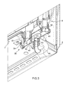
figure 3 shows a schematic view in perspective, with sectioned parts and parts removed for clarity, of a first detail of the oven offigures 1 and2 ; and -
figure 4 shows an exploded view in perspective of a second detail of the oven offigures 1 and2 . -
Number 1 infigures 1 and2 indicates as a whole an oven for baking food products comprising asupport frame 2 and abaking chamber 3, which is housed inside theframe 2 and is thermally insulated from theframe 2 itself by means of the interposition of a known insulating material, which is not shown. - The
chamber 3 presents an opening (not shown), which allows the food products to be introduced inside thechamber 3, it is formed in correspondence to afront wall 4 of theoven 1, it extends in a substantially vertical containing plane, and is closed by a door (not shown), which is hinged to theframe 2 so as to rotate, with respect to theframe 2 itself, around a fulcrum axis (not shown), which may be parallel or perpendicular to a substantiallyhorizontal direction 5. - The
oven 1 is provided, furthermore, with aheating device 51, which is arranged inside thechamber 3, so as to provide the heat needed to bake the food products present inside thechamber 3 itself. - The
oven 1 comprises, furthermore, afeeding unit 6, which is suited to feed steam into thechamber 3, and comprises, in turn, atank 7 for containing water, asteam generator 8 communicating with thetank 7, and afeeding circuit 9 for feeding the steam produced by thegenerator 8 itself into thechamber 3. - As shown in
figure 4 , thetank 7 comprises two shells 10, each of which preferably presents a substantially U-shaped form, is cup-shaped, presents a concavity facing the other shell 10, and is made of a polymeric material, in particular an injection-moulded polymeric material. The U-shaped form of each shells 10 allows thetank 7 to be mounted on a back wall of an oven surrounding a motor device (not shown in the figures) arranged on aseat 50 formed on said back wall. - One of the shells 10 (hereinafter referred to as 10a) preferably presents a
coupling rib 11, which extends along aperipheral edge 12 of theshell 10a, presents an annular shape, and, when the shells are coupled, it is housed inside anannular coupling seat 13, which is obtained along aperipheral edge 14 of the other shell (hereinafter referred to as 10b). - After the
rib 11 has been inserted into theseat 13, the twoshells figure 1 ), which extends in a containing plane that is substantially parallel to the opening (not shown) of thechamber 3. Theshells line 15 without the interposition of gaskets, in particular by means of welding, preferably but not necessarily by means of vibration welding. - With reference to
figures 1 ,2 , and4 , thetank 7 presents afirst sleeve 16, which is manufactured as one single piece together with theshell 10a, is preferably obtained substantially in correspondence to one lateral end of an upper section of theedge 12, projects upwards from theshell 10a, and is connected to afilling duct 17 for filling thetank 7 itself. - The
duct 17 extends between thewall 4 and thesleeve 16, and comprises aninlet section 18 inclined downwards and a substantiallyvertical outlet section 19, which are suited to allow thetank 7 to be filled with water by gravity. - The
tank 7 is provided, furthermore, with anair trap 20, which is manufactured partly on theshell 10a and partly on theshell 10b, and is obtained at the inlet of thesleeve 16, so as to prevent the steam from flowing along theduct 17 and from leaving theoven 1 through thewall 4. - The
tank 7 presents, furthermore, asecond sleeve 21, which is manufactured as one single piece together with theshell 10a, is preferably obtained in correspondence to an intermediate point of the upper section of theedge 12, projects upwards from theshell 10a, and is threaded on the outside, so as to allow the screwing of alevel sensor 22. - The
sensor 22 comprises a support rod 23 projecting inside thetank 7, and afloat 24, which is coupled to the rod 23 in a sliding manner, so as to move between a lowered position corresponding to the minimum water level in thetank 7 and a raised position corresponding to the maximum water level in he tank 7 itself. The position of the float 23 along the rod 23 can be sensed by a sensing device, known per se, that outputs a signal to a display device indicating intelligibly to a user, in one case, the emptying of thetank 7 and, in the other case, the complete filling of thetank 7 itself. - The
tank 7 is provided, furthermore, with athird sleeve 25, which is manufactured as one single piece together with theshell 10a, is preferably obtained in correspondence to a lateral end of a lower section of theedge 12, projects downwards from theshell 10a, and allows anoverflow duct 26 to be connected to thetank 7. - The
duct 26 comprises aninlet section 27, which is substantially vertical and projects inside thetank 7, and anoutlet section 28, which communicates with thechamber 3, and is inclined downwards, so as to discharge into thechamber 3, by gravity, the excess water introduced by a user into thetank 7. - The
tank 7 presents, furthermore, afourth sleeve 29, which is manufactured as one single piece together with theshell 10a, is preferably obtained in correspondence to a lateral end of the lower section of theedge 12 opposite to thesleeve 25, projects downwards from theshell 10a, and allows thetank 7 to be connected to the upper end of a substantiallyvertical duct 30, which defines part of thesteam generator 8, and is associated to aheating device 31, which is mounted on theduct 30 itself. - Due to the water evaporation in the
duct 30, thegenerator 8 feeds through the sleeve 29 a mixture, which consists partly of steam and partly of water, and is caused to move forward into aseparation chamber 32, which is shaped so as to allow the separation of water from the steam. - The
chamber 32 is preferably obtained in correspondence to an upper lateral portion of thetank 7, extends both above the level defined by the inlet of theoverflow duct 26 and above the level defined by the raised position of thefloat 24, and is limited on the upper side by a substantially horizontalinner deflector 33, which is manufactured as one single piece together with theshell 10a, and projects inside thetank 7 perpendicular to abottom wall 34 of theshell 10a, so as to deviate downwards and into thetank 7 the water fed through thesleeve 29. - The
chamber 32 communicates with thefeeding circuit 9 by means of afifth sleeve 35, which is manufactured as one single piece together with theshell 10a, is preferably obtained in correspondence to a lateral end of the upper section of theedge 12 opposite to thesleeve 16, projects horizontally from thewall 34 along a direction which is perpendicular to thehorizontal direction 5 and to the opening provided for introducing food products inside thechamber 3. Saidfifth sleeve 35 allows thetank 7 to be connected to afeeding duct 36, which defines part of thefeeding circuit 9, and feeds the steam to at least one delivery nozzle (not shown), which is mounted inside thechamber 3. - The
tank 7 presents, furthermore, asixth sleeve 37, which is manufactured as one single piece together with theshell 10a, is preferably obtained in correspondence to an intermediate point of the lower section of theedge 12, and projects downwards from theshell 10a itself. - With reference to
figures 3 and4 , thetank 7 is associated, furthermore, to afiltering device 38, which is mounted outside and beneath theshells shaped body 39, which is arranged with its concavity facing downwards, is hooked in a removable manner to thesixth sleeve 37 and to the lower end of thesteam generator duct 30, and is closed by alower lid 40, which is mounted in a removable manner on thebody 39 itself. - The
device 38 presents twoports 41, which are obtained through a bottom wall of thebody 39 and are respectively coupled to thesixth sleeve 37, so as to admit water insidebody 39, and to thesteam generator duct 30 to supply the latter with water and is provided with anoutlet 42, which is obtained through thelid 40. Theoutlet 42 is preferably interposed between the twoports 41 such that water passing from aport 41 to theother port 41 passes also overoutlet 42. - The
outlet 42 communicates withports 41 through a perforatedannular collar 43, which projects from thelid 40 into thebody 39, and extends around theoutlet 42, so as to prevent the limescale present in the water to reach theoutlet 42 itself. Theoutlet 42, furthermore, is connected to adischarge duct 44, which extends between thedevice 38 and thewall 4, and allows the user to empty thetank 7. - In order to limit the heat exchange between the part of the
tank 7 corresponding to thesleeve 16 and to theair trap 20 and the part of thetank 7 corresponding to theseparation chamber 32 and in order to guarantee a correct operation of thesensor 22, thetank 7 is provided with a plurality of substantially vertical dividing baffles 45 (in particular four baffles 45), which are manufactured as one single piece together with theshell 10a, project inside thetank 7 perpendicular to thewall 34, and are arranged at a given distance from theedge 12. - The
tank 7 is provided, furthermore, with a plurality offixing brackets 46, which are manufactured as one single piece together with theshell 10a, so a to allow thetank 7 to be fitted to theframe 2. If preferred, said plurality offixing brackets 46 may be formed as a single piece part on one of the twoshells - According to some variants that are not shown:
- each
sleeve 16 and/or 21 and/or 25 and/or 29 and/or 35 and/or 37 is manufactured as one single piece together with theshell 10b; - each
sleeve 16 and/or 21 and/or 25 and/or 29 and/or 35 and/or 37 is obtained partly on theshell 10a and partly on theshell 10b; in this way an inlet/outlet opening formed by each of said sleeve is divided by the tankshell junction line 15. - each dividing
baffle 45 is manufactured as one single piece together with theshell 10b; and - each dividing
baffle 45 is obtained partly on theshell 10a and partly on theshell 10b. - In use, the
tank 7 and theduct 30 of thesteam generator 8 are filled with water by the user through thefilling duct 17. - Once the
float 24 of thelevel sensor 22 has reached a position comprised between its lowered position and its raised position, or a position equal the latter, the food products to be baked have been inserted into thebaking chamber 3, and a steam cooking mode of operation has been selected, theheating device 31 is activated, so as to cause the evaporation of a water amount present in theduct 30. - The mixture of water and steam generated by the heating of the water present in the
duct 30 is fed through thesleeve 29 into theseparation chamber 32, where the water bounces against thedeflector 33, so as to be recirculated again in thetank 7, while the steam is fed, first of all, through thesleeve 35, then along theduct 36 of thefeeding circuit 9, and, finally, into thebaking chamber 3. - With reference to what has been described above, it should be pointed out that:
- the excess water introduced by the user into the
tank 7 through theduct 17 is discharged into thebaking chamber 3 through theoverflow duct 26; - at the end of one or more baking cycles, the
tank 7 may be emptied by the user through thedischarge duct 44; - the position and the shape of the
filtering device 38 allow an easy maintenance and cleaning of thefiltering device 38 itself by simply removing thelid 40 from thebody 39; - the permanent connection of the
shells whole tank 7 to be inserted in the assembly line of theoven 1; and - the fact that the
separation chamber 32 is built-in in thetank 7 allows a reduction of the number of components used while assembling theoven 1 itself. - In addition, a
tank 7 made according to the invention allows an easy installation of a waterlevel sensor device 22 that may be inspected/removed by thetank 7 at any time. Furthermore, the provision of one ormore sleeve shell 10a and partly on theshell 10b simplify the manufacture process of thetank 7 because reduces the number of runners to be installed in a mould when forming each of the twoshells more sleeve shells tank 7 is the same as the demoulding direction of each of the shells in the injection-moulding machine, and it is perpendicular to the tank shells assembly plane.
Claims (15)
- An oven for baking food products comprising a baking chamber (3), and a feeding unit (6) for feeding steam into the baking chamber (3), the feeding unit (6) comprising a tank (7) for containing water, a steam generator (8) in fluid communication with the tank (7), and a feeding circuit (9) for feeding steam produced by the steam generator (8) into the chamber (3); and characterised in that the tank (7) comprises two shells (10a, 10b), which are permanently connected to each other along a junction line (15).
- An oven according to claim 1, wherein the shells (10a, 10b) are connected to each other by means of welding, in particular vibration welding.
- An oven according to claim 1 or 2, wherein each shell (10a, 10b) is made of a polymeric material, in particular an injection-moulded polymeric material.
- An oven according to any of the previous claims, wherein the baking chamber (3) comprises an opening for the insertion of the food products to be baked and a closing door for closing the opening itself; the junction line (15) extending in a containing plane that is substantially parallel to said opening.
- An oven according to any of the previous claims, wherein one of the two shells (10a, 10b) presents a coupling rib (11) extending along said junction line (15), while the other presents a seat (13), which extends along said junction line (15), as well, so as to receive the coupling rib (11) itself.
- An oven according to any of the previous claims, wherein the feeding unit (6) comprises, furthermore, a separation chamber (32) for separating the mixture of water and steam fed by the steam generator (8) to the feeding circuit (9); the separation chamber (32) being manufactured as one single piece together with said shells (10a, 10b).
- An oven according to any of the previous claims, wherein the feeding unit (6) comprises, furthermore, an inlet (16, 17) of the water into the tank (7) and an air trap (20) for preventing the steam from reaching the outer environment through the inlet (16, 17) itself; the air trap (20) being manufactured as one single piece together with said shells (10a, 10b).
- An oven according to any of the previous claims, wherein the tank (7) presents, furthermore, at least one coupling sleeve (16, 25, 29, 35, 37) for connecting the tank (7) to a relative feeding duct (17, 26, 30, 36); the coupling sleeve (16, 25, 29, 35, 37) being manufactured as one single piece together with said shells (10a, 10b).
- An oven according to claim 8, wherein the coupling sleeve (16, 25, 29, 35, 37) is entirely obtained on one single shell (10a, 10b) or partly on one shell (10a, 10b) and partly on the other shell (10a, 10b).
- An oven according to any of the previous claims and comprising, furthermore, a support frame (2) of the baking chamber (3) and fixing means (46) for fitting the tank (7) to the support frame (2); the fixing means (46) being manufactured as one single piece together with at least one of said shells (10a, 10b).
- An oven according to any of the previous claims, wherein the feeding unit (6) comprises, furthermore, a level sensor (22) for detecting the water level inside the tank (7); the tank (7) presenting a connecting sleeve (21) manufactured as one single piece together with said shells (10a, 10b), so as to connect the level sensor (22) to the tank (7) itself.
- An oven according to any of the previous claims, wherein the tank (7) presents at least one inner dividing wall (45), which is substantially perpendicular to a containing plane of said junction line (15), said at least one inner dividing wall 45 being formed entirely on a single shell (10a, 10b) or partly on one shell (10a, 10b) and partly on the other shell (10b, 10a).
- An oven according to any of the previous claims, wherein the feeding unit (6) comprises, furthermore, a water discharge (44) for discharging the water from the tank (7) and a filtering device (38) for filtering the water fed to the discharge (44) itself; the filtering device (38) being mounted outside of said tank (7).
- An oven according to claim 13, wherein the filtering device (38) is connected to said shells (10a, 10b) in a removable manner.
- An oven according to claim 15 or 16, wherein the filtering device (38) comprises a first port (41) communicating with the tank (7), a second port (41) communicating with the steam generator (8), and an outlet (42) communicating with said discharge (44).
Priority Applications (6)
| Application Number | Priority Date | Filing Date | Title |
|---|---|---|---|
| EP12163668.2A EP2650615B2 (en) | 2012-04-11 | 2012-04-11 | Oven for baking food products |
| AU2013247086A AU2013247086B2 (en) | 2012-04-11 | 2013-03-12 | Oven for baking food products |
| US14/375,666 US10344988B2 (en) | 2012-04-11 | 2013-03-12 | Oven for baking food products |
| PCT/EP2013/054958 WO2013152912A1 (en) | 2012-04-11 | 2013-03-12 | Oven for baking food products |
| US16/434,315 US11466868B2 (en) | 2012-04-11 | 2019-06-07 | Oven for baking food products |
| US17/896,307 US20220404035A1 (en) | 2012-04-11 | 2022-08-26 | Oven for baking food products |
Applications Claiming Priority (1)
| Application Number | Priority Date | Filing Date | Title |
|---|---|---|---|
| EP12163668.2A EP2650615B2 (en) | 2012-04-11 | 2012-04-11 | Oven for baking food products |
Publications (3)
| Publication Number | Publication Date |
|---|---|
| EP2650615A1 true EP2650615A1 (en) | 2013-10-16 |
| EP2650615B1 EP2650615B1 (en) | 2018-01-10 |
| EP2650615B2 EP2650615B2 (en) | 2024-05-15 |
Family
ID=47844369
Family Applications (1)
| Application Number | Title | Priority Date | Filing Date |
|---|---|---|---|
| EP12163668.2A Active EP2650615B2 (en) | 2012-04-11 | 2012-04-11 | Oven for baking food products |
Country Status (4)
| Country | Link |
|---|---|
| US (3) | US10344988B2 (en) |
| EP (1) | EP2650615B2 (en) |
| AU (1) | AU2013247086B2 (en) |
| WO (1) | WO2013152912A1 (en) |
Cited By (3)
| Publication number | Priority date | Publication date | Assignee | Title |
|---|---|---|---|---|
| US10830430B2 (en) | 2012-09-10 | 2020-11-10 | Electrolux Home Products, Corporation N.V. | Steam system for a steam cooking appliance |
| EP4050267A1 (en) | 2021-02-25 | 2022-08-31 | Electrolux Appliances Aktiebolag | Cooking oven |
| US11493201B2 (en) | 2014-01-15 | 2022-11-08 | Electrolux Appliances Aktiebolag | Steam generator and household appliance |
Families Citing this family (15)
| Publication number | Priority date | Publication date | Assignee | Title |
|---|---|---|---|---|
| DE102014112521A1 (en) * | 2014-09-01 | 2016-03-03 | Miele & Cie. Kg | Cooking appliance |
| EP3865028A1 (en) | 2017-08-09 | 2021-08-18 | SharkNinja Operating LLC | Cooking device and components thereof |
| WO2019191400A1 (en) | 2018-03-29 | 2019-10-03 | Oerlikon Metco (Us) Inc. | Reduced carbides ferrous alloys |
| US20190309957A1 (en) * | 2018-04-09 | 2019-10-10 | Whirlpool Corporation | Steam generating system |
| US11051654B2 (en) | 2019-02-25 | 2021-07-06 | Sharkninja Operating Llc | Cooking device and components thereof |
| CN212788226U (en) | 2019-02-25 | 2021-03-26 | 沙克忍者运营有限责任公司 | cooking system |
| DE102019111796B4 (en) * | 2019-05-07 | 2026-03-19 | Rational Aktiengesellschaft | Assembly with a steam generator and a water connection tank |
| MX2022000309A (en) | 2019-07-09 | 2022-03-17 | Oerlikon Metco Us Inc | IRON-BASED ALLOYS DESIGNED FOR WEAR AND CORROSION RESISTANCE. |
| CN115379911A (en) | 2020-02-25 | 2022-11-22 | 欧瑞康美科(美国)公司 | Spheroidal tungsten carbide particles |
| US11647861B2 (en) | 2020-03-30 | 2023-05-16 | Sharkninja Operating Llc | Cooking device and components thereof |
| EP4393306A1 (en) * | 2022-12-30 | 2024-07-03 | Arçelik Anonim Sirketi | A water and steam separation tank for steam ovens |
| USD1138499S1 (en) | 2023-04-07 | 2026-08-04 | Whirlpool Corporation | Water reservoir for a steam oven |
| US20240389609A1 (en) * | 2023-05-25 | 2024-11-28 | Haier Us Appliance Solutions, Inc. | Water detection system and method for an indoor smoker |
| CN116423313B (en) | 2023-06-13 | 2023-08-11 | 成都理工大学 | A small-diameter inner wall grinding robot |
| DE102024115760A1 (en) | 2024-06-06 | 2025-12-11 | E.G.O. Elektro-Gerätebau GmbH | Device for generating steam and water-bearing household appliance with such a device |
Citations (2)
| Publication number | Priority date | Publication date | Assignee | Title |
|---|---|---|---|---|
| FR2614976A1 (en) * | 1987-05-06 | 1988-11-10 | Seb Sa | Electric oven for cooking food, comprising a steam generator |
| US20050087528A1 (en) * | 2002-06-05 | 2005-04-28 | Kouji Kanzaki | High frequency heating apparatus with steam generating function |
Family Cites Families (23)
| Publication number | Priority date | Publication date | Assignee | Title |
|---|---|---|---|---|
| US3915124A (en) * | 1974-08-07 | 1975-10-28 | Rockwell International Corp | Compact high-pressure steam generator |
| US4031911A (en) * | 1976-04-30 | 1977-06-28 | General Electric Company | Laundry machine improved water temperature control and method |
| DE2736291C2 (en) * | 1977-02-11 | 1983-04-07 | Eaton S.A.M., Monaco | Dosing device for adding a measured amount of liquid to the washing area, in particular a dishwasher |
| DE8131827U1 (en) * | 1981-10-31 | 1983-04-14 | Meister, Siegfried, 8910 Landsberg | DEVICE FOR HEAT-TREATING FOODSTUFFS BY MEANS OF A VAPOR-AIR MIXTURE |
| FR2653208B3 (en) † | 1989-10-13 | 1991-12-06 | Bonnet Sa | BOILER FOR THE STEAM SUPPLY OF A FOOD COOKING OVEN. |
| FR2669262B1 (en) * | 1990-11-21 | 1996-05-15 | Pierre Louis Agostini | PROCESS FOR THE MANUFACTURE OF CRACKS OR OTHER RECEPTACLES IN PLASTIC MATERIAL BY ASSEMBLING EXTRUDED PROFILE SECTION. |
| FR2678359B1 (en) | 1991-06-25 | 1993-09-17 | Soremam | AUTONOMOUS AND MODULAR STEAM GENERATOR FOR HOUSEHOLD COOKING APPLIANCES. |
| FR2707734B1 (en) † | 1993-07-16 | 1995-10-06 | Thirode Grandes Cuisines Poligny | Process for the continuous production of circulating water vapor, steam generator and installation using it. |
| FR2774103B1 (en) * | 1998-01-23 | 2000-03-03 | Seb Sa | WATER TANK FOR A STEAM IRON, AND METHOD FOR MANUFACTURING SUCH A TANK |
| DE19916494A1 (en) * | 1999-04-13 | 2000-10-19 | Mannesmann Vdo Ag | Method for producing a plastic component and fuel tank for a motor vehicle |
| US6101925A (en) † | 1999-10-12 | 2000-08-15 | Lundar Electric Industrial Co., Ltd. | Humidity device for oven |
| ITUD20030070A1 (en) * | 2003-03-27 | 2004-09-28 | Dihr Spa | DISCONTINUITY TANK FOR A WASHING EQUIPMENT, SUCH AS A DISHWASHER, A GLASSWASHER, A DISHWASHER, A WASHING MACHINE, OR SIMILAR. |
| KR100629336B1 (en) † | 2004-11-05 | 2006-09-29 | 엘지전자 주식회사 | Steam generator in steam oven |
| US20060249137A1 (en) * | 2005-05-03 | 2006-11-09 | Malcolm Reay | System and method for draining water from a steam oven |
| US7537004B2 (en) * | 2005-05-03 | 2009-05-26 | Whirlpool Corporation | Steam oven with fluid supply and drain vessel |
| JP3921226B2 (en) * | 2005-07-29 | 2007-05-30 | シャープ株式会社 | Cooker |
| US20070062927A1 (en) * | 2005-09-06 | 2007-03-22 | Sells Joel M | Steam generator system for a household oven |
| JP4311688B2 (en) * | 2006-11-02 | 2009-08-12 | シャープ株式会社 | Exhaust steam diluting apparatus and cooking device equipped with the same |
| DE102007048567B4 (en) * | 2007-10-09 | 2011-11-24 | Miele & Cie. Kg | Process for cleaning a system consisting of a tank and a water heater, and system |
| JP4586111B1 (en) * | 2009-04-16 | 2010-11-24 | シャープ株式会社 | Cooker |
| PL2264240T3 (en) * | 2009-06-18 | 2011-09-30 | Miele & Cie | Front loaded laundry treatment machine with steam creation device |
| DE102009044053A1 (en) * | 2009-09-18 | 2011-05-05 | Miele & Cie. Kg | Steam generator for a household appliance |
| US8997730B2 (en) * | 2011-11-29 | 2015-04-07 | Alto-Shaam, Inc. | Grease handling apparatus for closed system oven |
-
2012
- 2012-04-11 EP EP12163668.2A patent/EP2650615B2/en active Active
-
2013
- 2013-03-12 US US14/375,666 patent/US10344988B2/en active Active
- 2013-03-12 AU AU2013247086A patent/AU2013247086B2/en active Active
- 2013-03-12 WO PCT/EP2013/054958 patent/WO2013152912A1/en not_active Ceased
-
2019
- 2019-06-07 US US16/434,315 patent/US11466868B2/en active Active
-
2022
- 2022-08-26 US US17/896,307 patent/US20220404035A1/en active Pending
Patent Citations (2)
| Publication number | Priority date | Publication date | Assignee | Title |
|---|---|---|---|---|
| FR2614976A1 (en) * | 1987-05-06 | 1988-11-10 | Seb Sa | Electric oven for cooking food, comprising a steam generator |
| US20050087528A1 (en) * | 2002-06-05 | 2005-04-28 | Kouji Kanzaki | High frequency heating apparatus with steam generating function |
Cited By (5)
| Publication number | Priority date | Publication date | Assignee | Title |
|---|---|---|---|---|
| US10830430B2 (en) | 2012-09-10 | 2020-11-10 | Electrolux Home Products, Corporation N.V. | Steam system for a steam cooking appliance |
| US11493201B2 (en) | 2014-01-15 | 2022-11-08 | Electrolux Appliances Aktiebolag | Steam generator and household appliance |
| EP4050267A1 (en) | 2021-02-25 | 2022-08-31 | Electrolux Appliances Aktiebolag | Cooking oven |
| WO2022179816A1 (en) | 2021-02-25 | 2022-09-01 | Electrolux Appliances Aktiebolag | Cooking oven |
| US12663164B2 (en) | 2021-02-25 | 2026-06-23 | Electrolux Appliances Aktiebolag | Cooking oven |
Also Published As
| Publication number | Publication date |
|---|---|
| AU2013247086B2 (en) | 2017-04-20 |
| US20220404035A1 (en) | 2022-12-22 |
| US11466868B2 (en) | 2022-10-11 |
| WO2013152912A1 (en) | 2013-10-17 |
| US20150300654A1 (en) | 2015-10-22 |
| EP2650615B2 (en) | 2024-05-15 |
| US10344988B2 (en) | 2019-07-09 |
| AU2013247086A1 (en) | 2014-08-07 |
| EP2650615B1 (en) | 2018-01-10 |
| US20190285285A1 (en) | 2019-09-19 |
Similar Documents
| Publication | Publication Date | Title |
|---|---|---|
| US10344988B2 (en) | Oven for baking food products | |
| JP6059656B2 (en) | Water container and machine for making a beverage having the water container | |
| CA2829406C (en) | Cooking device with a steam-generating element | |
| EP2827057B1 (en) | Steam generator and heating cooker comprising steam generator | |
| US11698195B2 (en) | Electrical cooking appliance with automatic cleaning of cooking chamber | |
| EP2836075B1 (en) | Oven for baking food products | |
| CN104337382A (en) | Combination Oven with Reduced Smoke Flavor Transfer | |
| CN104126097A (en) | Steam oven with heatable water tray | |
| US20220110473A1 (en) | Dispenser preparing beverages from powders | |
| US20100154656A1 (en) | Heating cooker | |
| US10001283B2 (en) | Cooking device with fat drain | |
| CN209883843U (en) | Cooking utensil delivery system and cooking utensils | |
| CN213721379U (en) | Cooking device | |
| JP2010063595A (en) | Beverage feeder | |
| JP2010057799A (en) | Beverage dispenser | |
| KR101902713B1 (en) | Electric Grill | |
| CN112006553A (en) | Steaming and baking integrated machine | |
| JP7295130B2 (en) | Apparatus and method for producing extracted beverage | |
| CN208658939U (en) | Material cleaning device, cover assembly and cooking apparatus | |
| KR101597462B1 (en) | Large sized soup cooker | |
| JP2010063520A (en) | Beverage feeder | |
| CN211408588U (en) | Anti-siphon device and steam cooking device | |
| JP2010057798A (en) | Beverage dispenser | |
| CN109998381A (en) | Material cleaning device, cover assembly and cooking apparatus |
Legal Events
| Date | Code | Title | Description |
|---|---|---|---|
| PUAI | Public reference made under article 153(3) epc to a published international application that has entered the european phase |
Free format text: ORIGINAL CODE: 0009012 |
|
| AK | Designated contracting states |
Kind code of ref document: A1 Designated state(s): AL AT BE BG CH CY CZ DE DK EE ES FI FR GB GR HR HU IE IS IT LI LT LU LV MC MK MT NL NO PL PT RO RS SE SI SK SM TR |
|
| AX | Request for extension of the european patent |
Extension state: BA ME |
|
| 17P | Request for examination filed |
Effective date: 20140321 |
|
| RBV | Designated contracting states (corrected) |
Designated state(s): AL AT BE BG CH CY CZ DE DK EE ES FI FR GB GR HR HU IE IS IT LI LT LU LV MC MK MT NL NO PL PT RO RS SE SI SK SM TR |
|
| TPAC | Observations filed by third parties |
Free format text: ORIGINAL CODE: EPIDOSNTIPA |
|
| STAA | Information on the status of an ep patent application or granted ep patent |
Free format text: STATUS: EXAMINATION IS IN PROGRESS |
|
| 17Q | First examination report despatched |
Effective date: 20170123 |
|
| REG | Reference to a national code |
Ref country code: DE Ref legal event code: R079 Ref document number: 602012041757 Country of ref document: DE Free format text: PREVIOUS MAIN CLASS: F24C0015320000 Ipc: F22B0001280000 |
|
| RIC1 | Information provided on ipc code assigned before grant |
Ipc: A47J 27/04 20060101ALI20170725BHEP Ipc: F24C 15/32 20060101ALI20170725BHEP Ipc: F22B 1/28 20060101AFI20170725BHEP Ipc: F24C 15/00 20060101ALI20170725BHEP |
|
| GRAP | Despatch of communication of intention to grant a patent |
Free format text: ORIGINAL CODE: EPIDOSNIGR1 |
|
| STAA | Information on the status of an ep patent application or granted ep patent |
Free format text: STATUS: GRANT OF PATENT IS INTENDED |
|
| INTG | Intention to grant announced |
Effective date: 20170830 |
|
| GRAS | Grant fee paid |
Free format text: ORIGINAL CODE: EPIDOSNIGR3 |
|
| GRAA | (expected) grant |
Free format text: ORIGINAL CODE: 0009210 |
|
| STAA | Information on the status of an ep patent application or granted ep patent |
Free format text: STATUS: THE PATENT HAS BEEN GRANTED |
|
| AK | Designated contracting states |
Kind code of ref document: B1 Designated state(s): AL AT BE BG CH CY CZ DE DK EE ES FI FR GB GR HR HU IE IS IT LI LT LU LV MC MK MT NL NO PL PT RO RS SE SI SK SM TR |
|
| REG | Reference to a national code |
Ref country code: CH Ref legal event code: EP Ref country code: AT Ref legal event code: REF Ref document number: 962799 Country of ref document: AT Kind code of ref document: T Effective date: 20180115 |
|
| REG | Reference to a national code |
Ref country code: IE Ref legal event code: FG4D |
|
| REG | Reference to a national code |
Ref country code: DE Ref legal event code: R096 Ref document number: 602012041757 Country of ref document: DE |
|
| REG | Reference to a national code |
Ref country code: FR Ref legal event code: PLFP Year of fee payment: 7 |
|
| REG | Reference to a national code |
Ref country code: NL Ref legal event code: MP Effective date: 20180110 |
|
| REG | Reference to a national code |
Ref country code: AT Ref legal event code: MK05 Ref document number: 962799 Country of ref document: AT Kind code of ref document: T Effective date: 20180110 |
|
| PG25 | Lapsed in a contracting state [announced via postgrant information from national office to epo] |
Ref country code: NL Free format text: LAPSE BECAUSE OF FAILURE TO SUBMIT A TRANSLATION OF THE DESCRIPTION OR TO PAY THE FEE WITHIN THE PRESCRIBED TIME-LIMIT Effective date: 20180110 |
|
| PG25 | Lapsed in a contracting state [announced via postgrant information from national office to epo] |
Ref country code: FI Free format text: LAPSE BECAUSE OF FAILURE TO SUBMIT A TRANSLATION OF THE DESCRIPTION OR TO PAY THE FEE WITHIN THE PRESCRIBED TIME-LIMIT Effective date: 20180110 Ref country code: NO Free format text: LAPSE BECAUSE OF FAILURE TO SUBMIT A TRANSLATION OF THE DESCRIPTION OR TO PAY THE FEE WITHIN THE PRESCRIBED TIME-LIMIT Effective date: 20180410 Ref country code: LT Free format text: LAPSE BECAUSE OF FAILURE TO SUBMIT A TRANSLATION OF THE DESCRIPTION OR TO PAY THE FEE WITHIN THE PRESCRIBED TIME-LIMIT Effective date: 20180110 Ref country code: HR Free format text: LAPSE BECAUSE OF FAILURE TO SUBMIT A TRANSLATION OF THE DESCRIPTION OR TO PAY THE FEE WITHIN THE PRESCRIBED TIME-LIMIT Effective date: 20180110 Ref country code: ES Free format text: LAPSE BECAUSE OF FAILURE TO SUBMIT A TRANSLATION OF THE DESCRIPTION OR TO PAY THE FEE WITHIN THE PRESCRIBED TIME-LIMIT Effective date: 20180110 Ref country code: CY Free format text: LAPSE BECAUSE OF FAILURE TO SUBMIT A TRANSLATION OF THE DESCRIPTION OR TO PAY THE FEE WITHIN THE PRESCRIBED TIME-LIMIT Effective date: 20180110 |
|
| PG25 | Lapsed in a contracting state [announced via postgrant information from national office to epo] |
Ref country code: GR Free format text: LAPSE BECAUSE OF FAILURE TO SUBMIT A TRANSLATION OF THE DESCRIPTION OR TO PAY THE FEE WITHIN THE PRESCRIBED TIME-LIMIT Effective date: 20180411 Ref country code: IS Free format text: LAPSE BECAUSE OF FAILURE TO SUBMIT A TRANSLATION OF THE DESCRIPTION OR TO PAY THE FEE WITHIN THE PRESCRIBED TIME-LIMIT Effective date: 20180510 Ref country code: PL Free format text: LAPSE BECAUSE OF FAILURE TO SUBMIT A TRANSLATION OF THE DESCRIPTION OR TO PAY THE FEE WITHIN THE PRESCRIBED TIME-LIMIT Effective date: 20180110 Ref country code: SE Free format text: LAPSE BECAUSE OF FAILURE TO SUBMIT A TRANSLATION OF THE DESCRIPTION OR TO PAY THE FEE WITHIN THE PRESCRIBED TIME-LIMIT Effective date: 20180110 Ref country code: LV Free format text: LAPSE BECAUSE OF FAILURE TO SUBMIT A TRANSLATION OF THE DESCRIPTION OR TO PAY THE FEE WITHIN THE PRESCRIBED TIME-LIMIT Effective date: 20180110 Ref country code: RS Free format text: LAPSE BECAUSE OF FAILURE TO SUBMIT A TRANSLATION OF THE DESCRIPTION OR TO PAY THE FEE WITHIN THE PRESCRIBED TIME-LIMIT Effective date: 20180110 Ref country code: AT Free format text: LAPSE BECAUSE OF FAILURE TO SUBMIT A TRANSLATION OF THE DESCRIPTION OR TO PAY THE FEE WITHIN THE PRESCRIBED TIME-LIMIT Effective date: 20180110 Ref country code: BG Free format text: LAPSE BECAUSE OF FAILURE TO SUBMIT A TRANSLATION OF THE DESCRIPTION OR TO PAY THE FEE WITHIN THE PRESCRIBED TIME-LIMIT Effective date: 20180410 |
|
| REG | Reference to a national code |
Ref country code: DE Ref legal event code: R026 Ref document number: 602012041757 Country of ref document: DE |
|
| PLBI | Opposition filed |
Free format text: ORIGINAL CODE: 0009260 |
|
| PLAX | Notice of opposition and request to file observation + time limit sent |
Free format text: ORIGINAL CODE: EPIDOSNOBS2 |
|
| PG25 | Lapsed in a contracting state [announced via postgrant information from national office to epo] |
Ref country code: EE Free format text: LAPSE BECAUSE OF FAILURE TO SUBMIT A TRANSLATION OF THE DESCRIPTION OR TO PAY THE FEE WITHIN THE PRESCRIBED TIME-LIMIT Effective date: 20180110 Ref country code: AL Free format text: LAPSE BECAUSE OF FAILURE TO SUBMIT A TRANSLATION OF THE DESCRIPTION OR TO PAY THE FEE WITHIN THE PRESCRIBED TIME-LIMIT Effective date: 20180110 Ref country code: RO Free format text: LAPSE BECAUSE OF FAILURE TO SUBMIT A TRANSLATION OF THE DESCRIPTION OR TO PAY THE FEE WITHIN THE PRESCRIBED TIME-LIMIT Effective date: 20180110 |
|
| 26 | Opposition filed |
Opponent name: WEICKMANN & WEICKMANN PATENT- UND RECHTSANWAELTE P Effective date: 20181010 |
|
| PG25 | Lapsed in a contracting state [announced via postgrant information from national office to epo] |
Ref country code: CZ Free format text: LAPSE BECAUSE OF FAILURE TO SUBMIT A TRANSLATION OF THE DESCRIPTION OR TO PAY THE FEE WITHIN THE PRESCRIBED TIME-LIMIT Effective date: 20180110 Ref country code: DK Free format text: LAPSE BECAUSE OF FAILURE TO SUBMIT A TRANSLATION OF THE DESCRIPTION OR TO PAY THE FEE WITHIN THE PRESCRIBED TIME-LIMIT Effective date: 20180110 Ref country code: SM Free format text: LAPSE BECAUSE OF FAILURE TO SUBMIT A TRANSLATION OF THE DESCRIPTION OR TO PAY THE FEE WITHIN THE PRESCRIBED TIME-LIMIT Effective date: 20180110 Ref country code: SK Free format text: LAPSE BECAUSE OF FAILURE TO SUBMIT A TRANSLATION OF THE DESCRIPTION OR TO PAY THE FEE WITHIN THE PRESCRIBED TIME-LIMIT Effective date: 20180110 Ref country code: MC Free format text: LAPSE BECAUSE OF FAILURE TO SUBMIT A TRANSLATION OF THE DESCRIPTION OR TO PAY THE FEE WITHIN THE PRESCRIBED TIME-LIMIT Effective date: 20180110 |
|
| REG | Reference to a national code |
Ref country code: BE Ref legal event code: MM Effective date: 20180430 |
|
| GBPC | Gb: european patent ceased through non-payment of renewal fee |
Effective date: 20180411 |
|
| REG | Reference to a national code |
Ref country code: IE Ref legal event code: MM4A |
|
| PG25 | Lapsed in a contracting state [announced via postgrant information from national office to epo] |
Ref country code: LU Free format text: LAPSE BECAUSE OF NON-PAYMENT OF DUE FEES Effective date: 20180411 |
|
| PLBB | Reply of patent proprietor to notice(s) of opposition received |
Free format text: ORIGINAL CODE: EPIDOSNOBS3 |
|
| PG25 | Lapsed in a contracting state [announced via postgrant information from national office to epo] |
Ref country code: GB Free format text: LAPSE BECAUSE OF NON-PAYMENT OF DUE FEES Effective date: 20180411 Ref country code: BE Free format text: LAPSE BECAUSE OF NON-PAYMENT OF DUE FEES Effective date: 20180430 Ref country code: SI Free format text: LAPSE BECAUSE OF FAILURE TO SUBMIT A TRANSLATION OF THE DESCRIPTION OR TO PAY THE FEE WITHIN THE PRESCRIBED TIME-LIMIT Effective date: 20180110 |
|
| PG25 | Lapsed in a contracting state [announced via postgrant information from national office to epo] |
Ref country code: IE Free format text: LAPSE BECAUSE OF NON-PAYMENT OF DUE FEES Effective date: 20180411 |
|
| PG25 | Lapsed in a contracting state [announced via postgrant information from national office to epo] |
Ref country code: MT Free format text: LAPSE BECAUSE OF NON-PAYMENT OF DUE FEES Effective date: 20180411 |
|
| PG25 | Lapsed in a contracting state [announced via postgrant information from national office to epo] |
Ref country code: TR Free format text: LAPSE BECAUSE OF FAILURE TO SUBMIT A TRANSLATION OF THE DESCRIPTION OR TO PAY THE FEE WITHIN THE PRESCRIBED TIME-LIMIT Effective date: 20180110 |
|
| APBM | Appeal reference recorded |
Free format text: ORIGINAL CODE: EPIDOSNREFNO |
|
| APBP | Date of receipt of notice of appeal recorded |
Free format text: ORIGINAL CODE: EPIDOSNNOA2O |
|
| APAH | Appeal reference modified |
Free format text: ORIGINAL CODE: EPIDOSCREFNO |
|
| PG25 | Lapsed in a contracting state [announced via postgrant information from national office to epo] |
Ref country code: HU Free format text: LAPSE BECAUSE OF FAILURE TO SUBMIT A TRANSLATION OF THE DESCRIPTION OR TO PAY THE FEE WITHIN THE PRESCRIBED TIME-LIMIT; INVALID AB INITIO Effective date: 20120411 Ref country code: PT Free format text: LAPSE BECAUSE OF FAILURE TO SUBMIT A TRANSLATION OF THE DESCRIPTION OR TO PAY THE FEE WITHIN THE PRESCRIBED TIME-LIMIT Effective date: 20180110 |
|
| APBM | Appeal reference recorded |
Free format text: ORIGINAL CODE: EPIDOSNREFNO |
|
| APBP | Date of receipt of notice of appeal recorded |
Free format text: ORIGINAL CODE: EPIDOSNNOA2O |
|
| PG25 | Lapsed in a contracting state [announced via postgrant information from national office to epo] |
Ref country code: MK Free format text: LAPSE BECAUSE OF NON-PAYMENT OF DUE FEES Effective date: 20180110 |
|
| APBQ | Date of receipt of statement of grounds of appeal recorded |
Free format text: ORIGINAL CODE: EPIDOSNNOA3O |
|
| PLAB | Opposition data, opponent's data or that of the opponent's representative modified |
Free format text: ORIGINAL CODE: 0009299OPPO |
|
| R26 | Opposition filed (corrected) |
Opponent name: WEICKMANN & WEICKMANN PATENT- UND RECHTSANWAELTE PARTMBB Effective date: 20181010 |
|
| P01 | Opt-out of the competence of the unified patent court (upc) registered |
Effective date: 20230625 |
|
| APBU | Appeal procedure closed |
Free format text: ORIGINAL CODE: EPIDOSNNOA9O |
|
| PUAH | Patent maintained in amended form |
Free format text: ORIGINAL CODE: 0009272 |
|
| STAA | Information on the status of an ep patent application or granted ep patent |
Free format text: STATUS: PATENT MAINTAINED AS AMENDED |
|
| REG | Reference to a national code |
Ref country code: CH Ref legal event code: PK Free format text: DIE PUBLIKATION VOM 17.04.2024 WURDE AM 24.04.2024 IRRTUEMLICHERWEISE ERNEUT PUBLIZIERT. LA PUBLICATION DU 17.04.2024 A ETE REPUBLIEE PAR ERREUR LE 24.04.2024. LA PUBBLICAZIONE DEL 17.04.2024 E STATA ERRONEAMENTE RIPUBBLICATA IL 24.04.2024. |
|
| 27A | Patent maintained in amended form |
Effective date: 20240515 |
|
| AK | Designated contracting states |
Kind code of ref document: B2 Designated state(s): AL AT BE BG CH CY CZ DE DK EE ES FI FR GB GR HR HU IE IS IT LI LT LU LV MC MK MT NL NO PL PT RO RS SE SI SK SM TR |
|
| REG | Reference to a national code |
Ref country code: DE Ref legal event code: R102 Ref document number: 602012041757 Country of ref document: DE |
|
| PGFP | Annual fee paid to national office [announced via postgrant information from national office to epo] |
Ref country code: FR Payment date: 20240430 Year of fee payment: 13 |
|
| PGFP | Annual fee paid to national office [announced via postgrant information from national office to epo] |
Ref country code: DE Payment date: 20250428 Year of fee payment: 14 |
|
| PGFP | Annual fee paid to national office [announced via postgrant information from national office to epo] |
Ref country code: IT Payment date: 20250422 Year of fee payment: 14 |
|
| PGFP | Annual fee paid to national office [announced via postgrant information from national office to epo] |
Ref country code: CH Payment date: 20250501 Year of fee payment: 14 |
|
| PG25 | Lapsed in a contracting state [announced via postgrant information from national office to epo] |
Ref country code: FR Free format text: LAPSE BECAUSE OF NON-PAYMENT OF DUE FEES Effective date: 20250430 |