EP2650532A2 - Power Generator - Google Patents
Power Generator Download PDFInfo
- Publication number
- EP2650532A2 EP2650532A2 EP12187963.9A EP12187963A EP2650532A2 EP 2650532 A2 EP2650532 A2 EP 2650532A2 EP 12187963 A EP12187963 A EP 12187963A EP 2650532 A2 EP2650532 A2 EP 2650532A2
- Authority
- EP
- European Patent Office
- Prior art keywords
- shaft
- propeller
- generator
- speed
- rotor shaft
- Prior art date
- Legal status (The legal status is an assumption and is not a legal conclusion. Google has not performed a legal analysis and makes no representation as to the accuracy of the status listed.)
- Granted
Links
Images



Classifications
-
- F—MECHANICAL ENGINEERING; LIGHTING; HEATING; WEAPONS; BLASTING
- F03—MACHINES OR ENGINES FOR LIQUIDS; WIND, SPRING, OR WEIGHT MOTORS; PRODUCING MECHANICAL POWER OR A REACTIVE PROPULSIVE THRUST, NOT OTHERWISE PROVIDED FOR
- F03D—WIND MOTORS
- F03D9/00—Adaptations of wind motors for special use; Combinations of wind motors with apparatus driven thereby; Wind motors specially adapted for installation in particular locations
- F03D9/20—Wind motors characterised by the driven apparatus
- F03D9/25—Wind motors characterised by the driven apparatus the apparatus being an electrical generator
-
- F—MECHANICAL ENGINEERING; LIGHTING; HEATING; WEAPONS; BLASTING
- F03—MACHINES OR ENGINES FOR LIQUIDS; WIND, SPRING, OR WEIGHT MOTORS; PRODUCING MECHANICAL POWER OR A REACTIVE PROPULSIVE THRUST, NOT OTHERWISE PROVIDED FOR
- F03D—WIND MOTORS
- F03D15/00—Transmission of mechanical power
-
- F—MECHANICAL ENGINEERING; LIGHTING; HEATING; WEAPONS; BLASTING
- F03—MACHINES OR ENGINES FOR LIQUIDS; WIND, SPRING, OR WEIGHT MOTORS; PRODUCING MECHANICAL POWER OR A REACTIVE PROPULSIVE THRUST, NOT OTHERWISE PROVIDED FOR
- F03D—WIND MOTORS
- F03D7/00—Controlling wind motors
- F03D7/02—Controlling wind motors the wind motors having rotation axis substantially parallel to the air flow entering the rotor
- F03D7/022—Adjusting aerodynamic properties of the blades
- F03D7/0224—Adjusting blade pitch
-
- F—MECHANICAL ENGINEERING; LIGHTING; HEATING; WEAPONS; BLASTING
- F03—MACHINES OR ENGINES FOR LIQUIDS; WIND, SPRING, OR WEIGHT MOTORS; PRODUCING MECHANICAL POWER OR A REACTIVE PROPULSIVE THRUST, NOT OTHERWISE PROVIDED FOR
- F03D—WIND MOTORS
- F03D7/00—Controlling wind motors
- F03D7/02—Controlling wind motors the wind motors having rotation axis substantially parallel to the air flow entering the rotor
- F03D7/022—Adjusting aerodynamic properties of the blades
- F03D7/024—Adjusting aerodynamic properties of the blades of individual blades
-
- F—MECHANICAL ENGINEERING; LIGHTING; HEATING; WEAPONS; BLASTING
- F03—MACHINES OR ENGINES FOR LIQUIDS; WIND, SPRING, OR WEIGHT MOTORS; PRODUCING MECHANICAL POWER OR A REACTIVE PROPULSIVE THRUST, NOT OTHERWISE PROVIDED FOR
- F03D—WIND MOTORS
- F03D80/00—Details, components or accessories not provided for in groups F03D1/00 - F03D17/00
- F03D80/80—Arrangement of components within nacelles or towers
- F03D80/82—Arrangement of components within nacelles or towers of electrical components
- F03D80/85—Cabling
-
- F—MECHANICAL ENGINEERING; LIGHTING; HEATING; WEAPONS; BLASTING
- F03—MACHINES OR ENGINES FOR LIQUIDS; WIND, SPRING, OR WEIGHT MOTORS; PRODUCING MECHANICAL POWER OR A REACTIVE PROPULSIVE THRUST, NOT OTHERWISE PROVIDED FOR
- F03D—WIND MOTORS
- F03D80/00—Details, components or accessories not provided for in groups F03D1/00 - F03D17/00
- F03D80/80—Arrangement of components within nacelles or towers
- F03D80/88—Arrangement of components within nacelles or towers of mechanical components
-
- F—MECHANICAL ENGINEERING; LIGHTING; HEATING; WEAPONS; BLASTING
- F16—ENGINEERING ELEMENTS AND UNITS; GENERAL MEASURES FOR PRODUCING AND MAINTAINING EFFECTIVE FUNCTIONING OF MACHINES OR INSTALLATIONS; THERMAL INSULATION IN GENERAL
- F16H—GEARING
- F16H37/00—Combinations of mechanical gearings, not provided for in groups F16H1/00 - F16H35/00
- F16H37/02—Combinations of mechanical gearings, not provided for in groups F16H1/00 - F16H35/00 comprising essentially only toothed or friction gearings
- F16H37/04—Combinations of toothed gearings only
- F16H37/041—Combinations of toothed gearings only for conveying rotary motion with constant gear ratio
-
- F—MECHANICAL ENGINEERING; LIGHTING; HEATING; WEAPONS; BLASTING
- F03—MACHINES OR ENGINES FOR LIQUIDS; WIND, SPRING, OR WEIGHT MOTORS; PRODUCING MECHANICAL POWER OR A REACTIVE PROPULSIVE THRUST, NOT OTHERWISE PROVIDED FOR
- F03D—WIND MOTORS
- F03D80/00—Details, components or accessories not provided for in groups F03D1/00 - F03D17/00
- F03D80/70—Bearing or lubricating arrangements
-
- F—MECHANICAL ENGINEERING; LIGHTING; HEATING; WEAPONS; BLASTING
- F05—INDEXING SCHEMES RELATING TO ENGINES OR PUMPS IN VARIOUS SUBCLASSES OF CLASSES F01-F04
- F05B—INDEXING SCHEME RELATING TO WIND, SPRING, WEIGHT, INERTIA OR LIKE MOTORS, TO MACHINES OR ENGINES FOR LIQUIDS COVERED BY SUBCLASSES F03B, F03D AND F03G
- F05B2240/00—Components
- F05B2240/60—Shafts
- F05B2240/61—Shafts hollow
-
- F—MECHANICAL ENGINEERING; LIGHTING; HEATING; WEAPONS; BLASTING
- F05—INDEXING SCHEMES RELATING TO ENGINES OR PUMPS IN VARIOUS SUBCLASSES OF CLASSES F01-F04
- F05B—INDEXING SCHEME RELATING TO WIND, SPRING, WEIGHT, INERTIA OR LIKE MOTORS, TO MACHINES OR ENGINES FOR LIQUIDS COVERED BY SUBCLASSES F03B, F03D AND F03G
- F05B2260/00—Function
- F05B2260/40—Transmission of power
- F05B2260/403—Transmission of power through the shape of the drive components
- F05B2260/4031—Transmission of power through the shape of the drive components as in toothed gearing
-
- F—MECHANICAL ENGINEERING; LIGHTING; HEATING; WEAPONS; BLASTING
- F05—INDEXING SCHEMES RELATING TO ENGINES OR PUMPS IN VARIOUS SUBCLASSES OF CLASSES F01-F04
- F05B—INDEXING SCHEME RELATING TO WIND, SPRING, WEIGHT, INERTIA OR LIKE MOTORS, TO MACHINES OR ENGINES FOR LIQUIDS COVERED BY SUBCLASSES F03B, F03D AND F03G
- F05B2270/00—Control
- F05B2270/30—Control parameters, e.g. input parameters
- F05B2270/326—Rotor angle
-
- Y—GENERAL TAGGING OF NEW TECHNOLOGICAL DEVELOPMENTS; GENERAL TAGGING OF CROSS-SECTIONAL TECHNOLOGIES SPANNING OVER SEVERAL SECTIONS OF THE IPC; TECHNICAL SUBJECTS COVERED BY FORMER USPC CROSS-REFERENCE ART COLLECTIONS [XRACs] AND DIGESTS
- Y02—TECHNOLOGIES OR APPLICATIONS FOR MITIGATION OR ADAPTATION AGAINST CLIMATE CHANGE
- Y02E—REDUCTION OF GREENHOUSE GAS [GHG] EMISSIONS, RELATED TO ENERGY GENERATION, TRANSMISSION OR DISTRIBUTION
- Y02E10/00—Energy generation through renewable energy sources
- Y02E10/70—Wind energy
- Y02E10/72—Wind turbines with rotation axis in wind direction
Definitions
- Embodiments discussed herein are directed to a power generator.
- a propeller power generator that generates electrical power by rotating a propeller with wind, ocean current, and other fluids has been known.
- a wind power generator for example, converts mechanical energy of a propeller that rotates by receiving wind into electrical energy by using a generator.
- a propeller power generator may include a position sensor such as an encoder that detects the rotational position of a propeller of the generator.
- a position sensor such as an encoder that detects the rotational position of a propeller of the generator.
- Some power generators of related art have such a position sensor onto a propeller shaft.
- the position sensor detects the rotational position of the propeller shaft, thereby detecting the rotational position of the propeller. (Refer to Japanese Patent Application Laid-open No. 2011-208635 , for example.)
- the propeller shaft generally has a large shaft diameter, which may cause the position sensor to become larger when installed on the propeller shaft.
- a power generator includes: a rotor shaft, a slip ring, a detecting shaft, and a position sensor.
- the rotor shaft through which a wire from a propeller is inserted rotates with the propeller.
- the slip ring has one of its ends coupled to the rotor shaft.
- the detecting shaft provided at another end of the slip ring rotates along with the rotor shaft.
- the position sensor detects the rotational position of the detecting shaft, thereby detecting the rotational position of the propeller.
- a position sensor for detecting the rotational position of a propeller can be downsized.
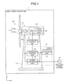
- FIG. 1 is a diagram illustrating a structure of a wind power generator according to a first embodiment.
- FIG. 2 is a schematic side view illustrating an arrangement of devices in a nacelle.
- FIG. 3 is a schematic diagram illustrating a relationship between a propeller and a slip ring.
- FIG. 4 is a schematic cross-sectional side view of a speed-increasing gear and a generator.
- FIG. 5 is a schematic cross-sectional side view of the slip ring.
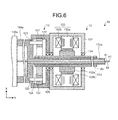
- FIG. 6 is a schematic cross-sectional side view illustrating another structure of the rotor shaft.
- FIGS. 7 and 8 are schematic side views illustrating different structures of devices in the nacelle.
- a power generator disclosed in the present application is applied to a wind power generator.
- the power generator disclosed in the present application can be also applied to a propeller power generator in addition to wind power generators.
- the power generator disclosed in the present application can be also applied to a tidal power generator, for example, which generates electrical power by rotating a propeller with ocean current.
- FIG. 1 is a diagram illustrating a structure of a wind power generator according to a first embodiment.
- a wind power generator 1 includes a wind power generating unit 10 and a power converter 20 so as to provide electrical power to an electric power system 30.
- a wind power generator 1 includes a wind power generating unit 10 and a power converter 20 so as to provide electrical power to an electric power system 30.
- some part of the structure is omitted from FIG. 1 .
- X and Y axes perpendicular to each other are specified. The positive direction in the X axis indicates the vertical upward direction.
- the wind power generating unit 10 includes a tower body 110, a windmill 140 having a nacelle 120 and a propeller 130.
- the propeller 130 includes a hub 130a and a plurality of blades 130b installed on different positions on the hub 130a.
- the plurality of blades 130b are provided with a pitch angle thereof variable.
- the pitch angle refers to an angle formed by a plane of rotation of the propeller 130 and a chord of the blade 130b.
- an area of the blade 130b receiving the wind becomes larger. In other words, because the drag of the blade 130b due to the wind becomes larger, a larger amount of energy can be obtained from the wind.
- the nacelle 120 is rotatably supported by the tower body 110.
- the nacelle 120 accommodates a generator 13 coupled to the propeller 130, through the propeller shaft 150.
- the generator 13 is a rotating electrical machine that can be used as a motor, such as a permanent magnet rotating electrical machine.
- the propeller shaft 150 is coupled to the hub 130a of the propeller 130.
- the electrical power generated by the generator 13 is output to the power converter 20, converted by the power converter 20, and supplied to the electric power system 30.
- the structure and operation of the power converter 20 will be described later.
- the nacelle 120 also includes a position sensor 16 for detecting the rotational position of the propeller 130 rotated by wind power.
- the position sensor 16 is an absolute value encoder that detects an absolute position. Therefore, it can detect the present rotational position of the propeller 130 without returning to the origin even when the propeller 130 is rotated due to, for example, a strong wind during the power-off state.
- the rotational position of the propeller 130 detected by the position sensor 16 is output to a pitch control unit 50 through an integrated control unit 40.
- the pitch control unit 50 After obtaining the rotational position of the propeller 130 through the integrated control unit 40, the pitch control unit 50 performs pitch control processing in which the pitch angle of each blade 130b is changed according to the rotational position of the propeller 130. Specific operations of the integrated control unit 40 and the pitch control unit 50 will be described later.
- the shaft diameter of the propeller shaft is usually formed somewhat larger from the viewpoint of strength or power generation efficiency. This may cause the position sensor to become larger when installing the position sensor for detecting the rotational position of the propeller to the propeller shaft, in order to detect the rotational position of the propeller by detecting the rotational position of the propeller shaft.
- the transmittable torque increases. This may put a large amount of mechanical stress onto the position sensor when installing the position sensor to the propeller shaft having a large shaft diameter.
- the propeller 130 includes some devices such as a pitch drive unit that varies the pitch angle of the blade 130b by driving the blade 130b.
- the nacelle 120 also accommodates a slip ring 15 for supplying electrical power to the devices.
- the wind power generator 1 includes a rotor shaft coupled to the propeller 130. Wires are inserted through the rotor shaft to which the slip ring 15 is installed.
- the slip ring 15 has a rotating unit to which wires from the propeller 130 are connected, and a fixed unit that is electrically coupled to the rotating unit. Wires from the propeller 130 are connected to external wires through the rotating unit and the fixed unit of the slip ring 15. This makes sending or receiving electrical power and signals possible between the devices rotating with and in the propeller 130 and external devices not rotating.
- the wind power generator 1 includes the rotor shaft rotating with the propeller 130 in addition to the propeller shaft 150. Therefore, in the wind power generator 1 according to the first embodiment, the rotational position of the propeller 130 is designed to be detected by detecting the rotational position of the rotor shaft by using the position sensor 16.
- the rotor shaft has a smaller shaft diameter than that of the propeller shaft 150. This can downsize the position sensor 16 compared with an example where the rotational position of the propeller shaft 150 is detected, thereby reducing the mechanical stress onto the position sensor 16.
- FIG. 2 is a schematic side view illustrating an arrangement of devices in the nacelle 120.
- the nacelle 120 accommodates a bearing 11, a speed-increasing gear 12, a brake 14, an output shaft 160, a rotor shaft 170, a detecting shaft 180 in addition to the generator 13, the slip ring 15, and the position sensor 16 described above.
- the bearing 11, the speed-increasing gear 12, the generator 13, the brake 14, the slip ring 15, and the position sensor 16 are arranged in this order from the closest side to the propeller 130.
- one side where the propeller 130 is provided is defined as the front of the wind power generator 1
- another side where the position sensor 16 is provided is defined as the rear of the wind power generator 1.
- an input shaft and an output shaft of the speed-increasing gear 12 are arranged coaxially with the central axis R of the propeller shaft 150 (i.e., the rotational axis of the propeller 130).
- This can downsize the nacelle 120 accommodating these devices. "coaxially" is not strictly necessary. That is, these shafts may have slightly offset from each other. The same shall apply hereinafter.
- the bearing 11 is, for example, a member supporting the propeller shaft 150 rotatably by using a roller bearing, for example.
- the speed-increasing gear 12 increases and outputs the rotational speed of the propeller shaft 150 to which the input shaft of the speed-increasing gear 12 is coupled to the propeller shaft 150.
- the input shaft and the output shaft of the speed-increasing gear 12 are arranged coaxially with the central axis R of the propeller shaft 150.
- the output shaft 160 illustrated in FIG. 2 corresponds to the output shaft of the speed-increasing gear 12. More specifically, in the first embodiment, an example is described where the output shaft 160 of the speed-increasing gear 12 is also the input shaft of the generator 13 and passes through and extends rearward of the generator 13. The present invention is, however, not limited to this example and the output shaft of the speed-increasing gear 12 may be formed separately from the input shaft of the generator 13.
- the generator 13 generates electrical power by using an output from the speed-increasing gear 12. Specifically, the generator 13 converts the rotational energy that is input from the output shaft 160 of the speed-increasing gear 12 into electrical energy. Similar to the speed-increasing gear 12, the input shaft of the generator 13 (i.e., the output shaft 160) is arranged coaxially with the propeller shaft 150. A specific structure of the speed-increasing gear 12 and the generator 13 will be described later with reference to FIG. 4 .
- the brake 14 is provided on a part of the output shaft 160 extending rearward of the generator 13.
- the brake 14 stops rotation of the propeller 130 by stopping rotation of the output shaft 160 with friction generated by the contact between the brake 14 and the output shaft 160.
- the brake 14 operates according to a command from the integrated control unit 40 (refer to FIG. 1 ), for example.
- the slip ring 15 is a current collector for sending or receiving electrical power and signals between the pitch drive unit or other devices in the propeller 130 and external devices.
- the slip ring 15 is coupled to the propeller 130 through the rotor shaft 170. The relation of connection between the propeller 130 and the slip ring 15 will be described with reference to FIG. 3.
- FIG. 3 is a schematic diagram illustrating a relationship between the propeller 130 and the slip ring 15.
- FIG. 3 In order to be understood easily, only one of the blades 130b is illustrated in FIG. 3 . Furthermore, only devices and wires provided corresponding to the single blade 130b are illustrated in FIG. 3 , while devices and wires provided corresponding to other blades 130b are omitted.
- the hub 130a of the propeller 130 includes a pitch drive unit 31 that varies the pitch angle of the blade 130b according to the command from the pitch control unit 50.
- the blade 130b includes a position sensor 32.
- the pitch drive unit 31 includes a gear 31a, a motor 31b, and an Alternate Current (AC) driver 31c.
- the pitch drive unit 31 drives the motor 31b by using the AC driver 31c. Rotation of the motor 31b rotates the gear 31a, thereby rotating the blade 130b coupled to the gear 31a. This changes the pitch angle of the blade 130b.
- the position sensor 32 is an absolute value encoder, for example, which detects and outputs the present pitch angle of the blade 130b to the pitch control unit 50.
- the AC driver 31c includes a power feed cable 81 and a signal wire 82, while the position sensor 32 includes a signal wire 83.
- the power feed cable 81 and the signal wires 82, 83 are coupled to the rotating unit 151 of the slip ring 15.
- a fixed unit 152 of the slip ring 15 is coupled to the pitch control unit 50 and a power feed unit 60.
- the fixed unit 152 is structured so as to maintain electrical connection with the rotating unit 151 even while the rotating unit 151 is rotating with the propeller 130.
- the pitch drive unit 31 and the position sensor 32 in the propeller 130 are electrically coupled to the pitch control unit 50 and the power feed unit 60 through the rotating unit 151 and the fixed unit 152 of the slip ring 15.
- a specific structure of the slip ring 15 will be described later with reference to FIG. 5 .
- the pitch control unit 50 obtains pitch angle information of the blade 130b from the position sensor 32 through the signal wire 83 and the slip ring 15, and sends a control signal to the AC driver 31c through the slip ring 15 and the signal wire 82.
- the power feed unit 60 supplies electrical power to the AC driver 31c through the slip ring 15 and the power feed cable 81.
- providing the slip ring 15 can electrically couple the pitch drive unit 31 and the position sensor 32 that are on the rotating unit side to the pitch control unit 50 and the power feed unit 60 on the fixed unit side.
- the power feed cable 81 and the signal wires 82, 83 are inserted through inside the rotor shaft 170 so as to be coupled to the rotating unit 151 of the slip ring 15.
- the rotor shaft 170 is arranged coaxially with the propeller shaft 150 (refer to FIG. 2 ) with one of its ends being secured to the propeller 130 and the other end being coupled to the rotating unit 151 of the slip ring 15.
- the rotating unit 151 of the slip ring 15 is coupled to the propeller 130 through the rotor shaft 170, whereby the rotating unit 151 rotates integrally with, and coaxially with the propeller 130.
- the detecting shaft 180 is provided on the rear side of the rotating unit 151 of the slip ring 15.
- the rotational position of the propeller 130 can be detected by detecting the rotational position of the detecting shaft 180 by using the position sensor 16.
- the detecting shaft 180 has no wire inserted therethrough from the propeller 130, unlike the rotor shaft 170. Therefore, the detecting shaft 180 can be formed into solid having the similar strength to that of the rotor shaft 170, thereby reducing the shaft diameter than that of the rotor shaft 170.
- the position sensor 16 is provided on the detecting shaft 180, whereby the position sensor 16 can be further downsized and the mechanical stress onto the position sensor 16 can be further reduced.
- the position sensor 16 is coupled to the propeller 130 through only a shaft rotating at the same rotational speed as the propeller 130, without a transmission mechanism such as a speed-increasing gear or a reducer interposed therebetween. As a result, the position sensor 16 can accurately detect the rotational position of the propeller 130.
- FIG. 4 is a schematic cross-sectional side view of the speed-increasing gear 12 and the generator 13.
- the propeller shaft 150 is a hollow member having both open ends.
- the propeller shaft 150 is coupled to the hub 130a of the propeller 130 at the front end, and rotates with the propeller 130.
- the propeller shaft 150 is a shaft for transmitting the rotation of the propeller 130 to the input shaft of the speed-increasing gear 12.
- the propeller shaft 150 herein is defined as a propeller shaft extending from one end coupled to the hub 130a to the other end coupled to the input shaft of the speed-increasing gear 12.
- “hollow shape” is not limited to the shape shown in the embodiment. The same shall apply hereinafter.
- the speed-increasing gear 12 has a frame 121 formed in a tubular shape and includes therein a ring 122, a coupling shaft 123, a planetary gear 124, and a bearing 125.
- the frame 121 is secured to the nacelle 120 by a support (not illustrated), for example.
- the ring 122 is an input shaft of the speed-increasing gear 12.
- the ring 122 is secured to the propeller shaft 150 through the coupling shaft 123, and has the same central axis as the central axis R of the propeller shaft 150 (refer to FIG. 2 ).
- the ring 122 is fitted into a groove in the frame 121 rotatably.
- the planetary gear 124 is arranged rotatably between an inner periphery of the ring 122 and an outer periphery of the output shaft 160.
- the output shaft 160 is an output shaft of the speed-increasing gear 12, having a smaller shaft diameter than that of the propeller shaft 150, and has the same central axis as that of the propeller shaft 150.
- the output shaft 160 is rotatably supported by the bearing 125 secured to the frame 121.
- the ring 122 rotates along with the rotation of the hub 130a of the propeller 130.
- the planetary gear 124 rotates on its axis, and rotates around the output shaft 160. Rotation of the planetary gear 124 rotates the output shaft 160.
- the rotational speed of the propeller shaft 150 i.e., the rotational speed of the propeller 130
- the speed-increasing gear 12 is increased by the speed-increasing gear 12 and output from the output shaft 160. Accordingly, the output shaft 160 rotates at a higher speed than the propeller 130.
- the speed-increasing gear 12 has a one-stage planetary gear mechanism, however, the speed-increasing gear 12 may have a multistage planetary gear mechanism.
- the multistage planetary gear mechanism can rotate the output shaft 160 at a higher speed increasing ratio.
- the speed-increasing gear 12 described above is a planetary gear type, however, the present invention is not limited to this example.
- the speed-increasing gear 12 may be a planetary roller type, for example. Because the planetary gear mechanism or the planetary roller mechanism can distribute the load to its planetary gear or planetary roller, abrasion, gear crack, and other defects are relatively unlikely to occur. Therefore, constituting the speed-increasing gear 12 only with a planetary gear mechanism or a planetary roller mechanism can increase the reliability of the wind power generator 1.
- an input shaft and an output shaft can be arranged coaxially.
- the propeller shaft 150, the speed-increasing gear 12, the generator 13, the slip ring 15, and the position sensor 16 can be arranged coaxially.
- the rotor shaft 170 arranged coaxially with the propeller shaft 150 can be inserted through a hollow part of the output shaft 160 so as to be coupled to the propeller 130.
- the propeller shaft 150 is couple to the ring 122, however, the propeller shaft 150 may be coupled to the planetary gear 124 through a coupling shaft.
- the planetary gear 124 serves as the input shaft of the speed-increasing gear 12.
- the generator 13 generates electrical power by using the rotation of the output shaft 160.
- the generator 13 includes a frame 131, a stator 132, a rotor 133, and a bearing 134.
- the frame 131 is formed in a tubular shape, for example, and secured to the nacelle 120 by a support (not illustrated).
- the bearing 134 supporting the output shaft 160 rotatably is secured to the frame 131.
- the output shaft 160 extends rearward of the generator 13 in order to install the brake 14, however, the output shaft 160 does not need to extend rearward of the generator 13.
- the wind power generator 1 may have a brake on the propeller shaft 150, whereby the brake stops the rotation of the propeller shaft 150 so as to stop the propeller 130.
- the stator 132 On the inner periphery of the frame 131 of the generator 13, the stator 132 is fastened.
- the stator 132 includes a stator core 132a and a stator coil 132b.
- the rotor 133 On the inner periphery side of the stator 132, the rotor 133 is arranged opposite to the stator 132 with a gap interposed therebetween.
- the rotor 133 includes a tubular rotor core 133a provided on the outer periphery of the output shaft 160 and a plurality of permanent magnets 133b arranged along the outer periphery of the rotor core 133a, and rotates coaxially with the output shaft 160.
- the rotor 133 rotates along with the rotation of the output shaft 160, thereby generating electric current on the stator coil 132b of the stator 132.
- the frame 131 of the generator 13 is secured to the frame 121 of the speed-increasing gear 12. That is, the frame 131 of the generator 13 is formed integrally with the frame 121 of the speed-increasing gear 12.
- the generator 13 is structured so that the output shaft 160 that is the output shaft of the speed-increasing gear 12 and also the input shaft of the generator 13 is not exposed to the outside between the speed-increasing gear 12 and the generator 13 (i.e., covered by the frame 121 and the frame 131).
- the nacelle 120 accommodating the generator 13 and the speed-increasing gear 12 can be downsized.
- the output shaft 160 is a hollow member having both open ends and arranged coaxially with the propeller shaft 150 as described above.
- the rotor shaft 170 is inserted through the hollow part of the output shaft 160.
- the rotor shaft 170 is arranged coaxially with the propeller shaft 150 and the output shaft 160, and inserted through the hollow part of the output shaft 160 (i.e., the hollow part of the speed-increasing gear 12 and the generator 13) and the hollow part of the propeller shaft 150 so as to be secured to the hub 130a of the propeller 130.
- the rotor shaft 170 is formed in a hollow shape having both open ends. Through the rotor shaft 170, the wires from the propeller 130 (the power feed cable 81, the signal wires 82, 83 and the like) are inserted.
- the rotor shaft 170 is coupled to the rotating unit 151 of the slip ring 15 at the other end.
- the position sensor 16 according to the first embodiment is coupled to the rotor shaft 170 through the rotating unit 151 of the slip ring 15 and the detecting shaft 180.
- FIG. 5 is a schematic cross-sectional side view of the slip ring 15.
- the slip ring 15 includes the rotating unit 151, the fixed unit 152, a frame 153, and a bearing 154.
- the frame 153 is secured to the nacelle 120 by a support (not illustrated), for example.
- the rotating unit 151 is a tubular member in a hollow shape, having an open front end.
- the rotating unit 151 is coupled to the rotor shaft 170 at the front end, and has the same central axis as that of the rotor shaft 170.
- the rotating unit 151 is rotatably supported by the bearing 154 secured to the frame 153. Accordingly, the rotating unit 151 rotates integrally with the propeller 130 and the rotor shaft 170.
- the collector rings 151a, 151b, 151c are provided to which the power feed cable 81 and the signal wires 82,83 inserted through the hollow part of the output shaft 160 are coupled respectively.
- the fixed unit 152 includes terminals 152a, 152b, 152c secured to the frame 153 and brushes 152d, 152e, 152f provided to the terminals 152a, 152b, 152c, respectively.
- the brushes 152d, 152e, 152f are retained while being contacted with the collector rings 151a, 151b, 151c respectively. As a result, even while the rotating unit 151 is rotating, electrical connection between the collector rings 151a, 151b, 151c, and the brushes 152d, 152e, 152f are maintained.
- the terminal 152a is coupled to the power feed unit 60, while the terminals 152b and 152c are coupled to the pitch control unit 50.
- the rotating unit 151 rotates integrally with the rotor shaft 170 and the propeller 130, and the brushes 152d, 152e, 152f of the fixed unit 152 slidingly contact with the collector rings 151a, 151b, 151c of the rotating unit 151 that is rotating.
- the pitch drive unit 31 and the position sensor 32 arranged in the propeller 130 are electrically coupled to the pitch control unit 50 or the power feed unit 60.
- the rotating unit 151 of the slip ring 15 is coupled to the rotor shaft 170 at one end, and rotates integrally with the rotor shaft 170 and the propeller 130.
- the detecting shaft 180 having a smaller shaft diameter than the rotor shaft 170 is coupled.
- the detecting shaft 180 is arranged coaxially with the propeller shaft 150, the rotor shaft 170, and the rotating unit 151.
- the detecting shaft 180 includes a first shaft 180a, a second shaft 180b, and a shaft coupling 180c.
- the first shaft 180a is secured to the rotating unit 151, while the second shaft 180b is secured to the position sensor 16.
- the first shaft 180a and the second shaft 180b are coupled by the shaft coupling 180c so as to have the same central axis.
- the detecting shaft 180 is arranged coaxially with the rotor shaft 170 and the rotating unit 151, and rotates integrally with the rotating unit 151.
- the position sensor 16 can detect the rotational position of the propeller 130 by detecting the rotational position of the detecting shaft 180.
- the rotational position of the propeller 130 detected by the position sensor 16 is output to the integrated control unit 40 from which, in turn, the information is output to the pitch control unit 50 and the power converter 20.
- the power converter 20, the integrated control unit 40, and the pitch control unit 50 will be described with reference to FIG. 1 again.
- the power converter 20 includes a power conversion unit 21, a conversion control unit 22, and an operation unit 23.
- the power converter 20 is arranged in the tower body 110.
- the power conversion unit 21 converts electrical power between the generator 13 of the wind power generating unit 10 and the electric power system 30 bidirectionally.
- a matrix converter for example, can be used as the power conversion unit 21.
- the conversion control unit 22 outputs a control signal to the power conversion unit 21 so as to perform generation control processing that enables the power conversion unit 21 to convert electrical power from the generator 13 to the electric power system 30.
- electrical power generated by the generator 13 is converted from DC to DC by the power conversion unit 21 and supplied to the electric power system 30.
- the conversion control unit 22 outputs a control signal to the power conversion unit 21 so as to enable the power conversion unit 21 to convert electrical power from the electric power system 30 to the generator 13. Accordingly, the conversion control unit 22 also performs propeller position control processing that controls the rotational position of the propeller 130 by using the generator 13 as a motor. The propeller position control processing is performed based on an operation to the operation unit 23 during replacement of the blade 130b, for example.
- the conversion control unit 22 generates the control signals so as to match the rotational position of the propeller 130 to an objective position, based on the rotational position of the propeller 130 detected by the position sensor 16 and the objective position specified by the operation to the operation unit 23. Then, the conversion control unit 22 outputs the control signal thus generated to the power conversion unit 21.
- the rotational position of the propeller 130 can be set to a preset objective position for each blade 130b, a position where each blade 130b can be installed or removed easily, for example.
- the conversion control unit 22 outputs the control signals to the power conversion unit 21 so as to enable the power conversion unit 21 to convert electrical power bidirectionally between the generator 13 and the electric power system 30, thereby performing generation control processing or propeller position control processing.
- the wind power generator 1 further includes integrated control unit 40 and the pitch control unit 50 so as to perform pitch control processing in which the pitch angle of the blade 130b are changed according to a position of the blade 130b, based on the rotational position of the propeller 130 that is output from the position sensor 16.
- the integrated control unit 40 is provided in the tower body 110, for example, while the pitch control unit 50 is provided in the nacelle 120, for example.
- the integrated control unit 40 obtains the rotational position of the propeller 130 from the position sensor 16, and outputs the rotational position information thus obtained to the pitch control unit 50. As described above, the rotational position of the propeller 130 detected by the position sensor 16 is input to the pitch control unit 50 through the integrated control unit 40.
- the pitch control unit 50 After obtaining the rotational position of the propeller 130 detected by the position sensor 16 through the integrated control unit 40, the pitch control unit 50 generates a pitch angle change command for each blade 130b according to the rotational position of the propeller 130, and changes the pitch angle of each blade 130b based on the pitch angle change command thus generated.
- the wind power generator 1 includes the rotor shaft 170, the slip ring 15, the detecting shaft 180, and the position sensor 16.
- the rotor shaft 170 through which the wires from the propeller 130 are inserted rotates integrally with the propeller 130.
- the slip ring 15 is coupled to the rotor shaft 170 at one end.
- the detecting shaft 180 is provided at the other end of the slip ring 15 and rotates along with the rotor shaft 170.
- the position sensor 16 detects the rotational position of the detecting shaft 180, thereby detecting the rotational position of the propeller 130.
- the rotational position of the detecting shaft 180 having a smaller shaft diameter than that of the propeller shaft 150 is detected by the position sensor 16. This can downsize the position sensor 16 compared with an example where the rotational position of the propeller shaft 150 is detected by the position sensor 16.
- the propeller shaft 150, the input shaft (the ring 122) and the output shaft 160 of the speed-increasing gear 12, the input shaft (i.e., the output shaft 160) of the generator 13, the rotor shaft 170, and the detecting shaft 180 are arranged coaxially. This can downsize the nacelle 120 where these devices are accommodated.
- the input shaft (ring 122) and the output shaft 160 of the speed-increasing gear 12, the input shaft (i.e., the output shaft 160) of the generator 13 are all formed in a hollow shape, so that the rotor shaft 170 is inserted in the hollow parts of the speed-increasing gear 12 and the generator 13.
- the devices can be more compactly arranged in the nacelle 120.
- the rotor shaft 170 can be formed straight, whereby the central axis of the rotor shaft 170 can be easily aligned with the central axis R of the propeller shaft 150.
- the position sensor 16 is arranged, for example, in the rearmost position among the devices in the nacelle 120 as illustrated in FIG. 2 . This facilitates installation, removal, or maintenance of the position sensor 16.
- the rotor shaft 170 is provided on the propeller 130, thereby transmitting the rotation of the propeller 130 more directly to the position sensor 16.
- the rotor shaft 170 is provided on the propeller 130, however, the rotor shaft 170 does not need to be coupled to the propeller 130 directly.
- FIG. 6 is a schematic cross-sectional side view illustrating another structure of the rotor shaft 170.
- components similar to the components that have already been described are designated by reference numerals similar to those of the components that have already been described, and overlapped explanation thereof will be omitted.
- a rotor shaft 170a is provided on a propeller shaft 150a.
- the propeller shaft 150a and the rotor shaft 170a may be formed integrally with each other, or formed as a respective separate body to be coupled to each other thereafter.
- the rotor shaft 170a is arranged coaxially with the propeller shaft 150a to be coupled to the front side of a slip ring 15.
- the rotor shaft 170a is formed in a hollow shape. Wires from a hub 130a (the power feed cable 81, the signal wires 82, 83, for example) are inserted through the propeller shaft 150a and the rotor shaft 170a to be coupled to the rotating unit 151 of the slip ring 15.
- the rotor shaft 170a may be coupled to the propeller 130 through the propeller shaft 150a. Even in this example, the rotor shaft 170a rotates integrally with the hub 130a of the propeller 130 like the first embodiment, the rotational position of the propeller 130 can be detected by detecting the rotational position of the rotor shaft 170a by using the position sensor 16.
- providing the rotor shaft 170a on the propeller shaft 150a facilitates axial alignment of the propeller shaft 150a and the rotor shaft 170a.
- the present invention is not limited to the example illustrated in FIG. 6 .
- the rotor shaft may be secured to both the propeller and the propeller shaft, or may be provided on the propeller or the propeller shaft with other members provided on the propeller or the propeller shaft interposed.
- FIG. 7 and FIG. 8 are schematic side views illustrating other structures of devices in the nacelle 120.
- a wind power generator 1c may be a so-called direct drive wind power generator that directly transmits rotation of a propeller 130_2 to a generator 13c without interposing a speed-increasing gear.
- the wind power generator 1c according to this example does not include a speed-increasing gear, unlike the wind power generators 1 nor 1a according to the embodiments described above.
- the generator 13c, a brake 14c, the slip ring 15, and a position sensor 16c are arranged in this order from the closest side to the propeller 130_2.
- the generator 13c is a type of a generator whose rated rotational speed is smaller than that of the generator 13 according to the embodiments described above.
- An output shaft 160c is an output shaft of the generator 13c, and formed integrally with a propeller shaft 150c, for example.
- the output shaft 160c is formed in a hollow shape.
- the output shaft 160c, a rotor shaft 170c, and the detecting shaft 180 are arranged coaxially with the propeller shaft 150c that is an input shaft of the generator 13c.
- the rotor shaft 170c rotates integrally with the propeller 130_2 while being inserted through a hollow part of the output shaft 160c and a hollow part of the propeller shaft 150c.
- the rotor shaft 170c may be provided on a hub 130a_2 like the rotor shaft 170 according to the first embodiment, otherwise provided on the propeller shaft 150c like the rotor shaft 170a according to the second embodiment.
- the position sensor 16c according to the third embodiment is coupled to the propeller 130_2 through the rotor shaft 170c, the slip ring 15, and the detecting shaft 180. Similar to the embodiments described above, the position sensor 16c according to the third embodiment detects the rotational position of the detecting shaft 180, thereby detecting the rotational position of the propeller 130_2.
- the power generator disclosed in the present application can be applied to direct drive wind power generators.
- a wind power generator 1d may be a wind power generator where an input shaft of a generator 13d is not arranged coaxially with a propeller shaft 150d.
- a speed-increasing gear 12d is structured so that a planetary speed-increasing gear and a gear pair with parallel axes are combined multistagedly, for example, so as to have a higher speed increasing ratio compared with that of the speed-increasing gear 12 described above.
- An output shaft 160d is an output shaft of a speed-increasing gear 12d.
- the output shaft 160d is arranged along a different axis from the central axis of the propeller shaft 150d, unlike the wind power generators 1, 1a, 1c according to the embodiments described above.
- the generator 13d generates electrical power by rotation of the output shaft 160d to which it is coupled.
- the output shaft 160d has a brake 14d.
- the propeller shaft 150d is coupled to a hub 130a_3 of a propeller 130_3 at one end, and coupled to an input shaft of a speed-increasing gear 12d at another end.
- the propeller shaft 150d and the input shaft of the speed-increasing gear 12d are both formed in a hollow shape, through which a rotor shaft 170d is inserted.
- the rotor shaft 170d rotates integrally with the propeller 130_3 while being inserted through a hollow part of the propeller shaft 150d and a hollow part of the speed-increasing gear 12d.
- the rotor shaft 170d may be provided on a hub 130a_3 similar to the rotor shaft 170 according to the first embodiment, otherwise provided on the propeller shaft 150d similar to the rotor shaft 170a according to the second embodiment.
- the rotor shaft 170d and the detecting shaft 180 are arranged coaxially with the propeller shaft 150d.
- a position sensor 16d according to the third embodiment is coupled to the propeller 130_3 through the rotor shaft 170d, the slip ring 15 and the detecting shaft 180. Similar to the embodiments described above, the position sensor 16d detects the rotational position of the detecting shaft 180, thereby detecting the rotational position of the propeller 130_3.
- the power generator disclosed in the present application can be also applied to a type of a wind power generator where an input shaft of a generator is not arranged coaxially with a propeller shaft.
Landscapes
- Engineering & Computer Science (AREA)
- General Engineering & Computer Science (AREA)
- Mechanical Engineering (AREA)
- Sustainable Energy (AREA)
- Chemical & Material Sciences (AREA)
- Combustion & Propulsion (AREA)
- Life Sciences & Earth Sciences (AREA)
- Sustainable Development (AREA)
- Power Engineering (AREA)
- Physics & Mathematics (AREA)
- Fluid Mechanics (AREA)
- Wind Motors (AREA)
- Connection Of Motors, Electrical Generators, Mechanical Devices, And The Like (AREA)
Abstract
Description
- Embodiments discussed herein are directed to a power generator.
- A propeller power generator that generates electrical power by rotating a propeller with wind, ocean current, and other fluids has been known. A wind power generator, for example, converts mechanical energy of a propeller that rotates by receiving wind into electrical energy by using a generator.
- A propeller power generator may include a position sensor such as an encoder that detects the rotational position of a propeller of the generator. Some power generators of related art have such a position sensor onto a propeller shaft. The position sensor detects the rotational position of the propeller shaft, thereby detecting the rotational position of the propeller. (Refer to Japanese Patent Application Laid-open No.
2011-208635 - However, the propeller shaft generally has a large shaft diameter, which may cause the position sensor to become larger when installed on the propeller shaft.
- In view of the disadvantage described above, it is an object of an aspect of an embodiment to provide a power generator whose position sensor for detecting the rotational position of a propeller can be downsized.
- A power generator according to an aspect of an embodiment includes: a rotor shaft, a slip ring, a detecting shaft, and a position sensor. The rotor shaft through which a wire from a propeller is inserted rotates with the propeller. The slip ring has one of its ends coupled to the rotor shaft. The detecting shaft provided at another end of the slip ring rotates along with the rotor shaft. The position sensor detects the rotational position of the detecting shaft, thereby detecting the rotational position of the propeller.
- According to an aspect of an embodiment, a position sensor for detecting the rotational position of a propeller can be downsized.
- The present invention can be appreciated more completely and advantages thereof can be easily understood in the description of embodiments below with reference to the accompanying drawings.
-
FIG. 1 is a diagram illustrating a structure of a wind power generator according to a first embodiment. -
FIG. 2 is a schematic side view illustrating an arrangement of devices in a nacelle. -
FIG. 3 is a schematic diagram illustrating a relationship between a propeller and a slip ring. -
FIG. 4 is a schematic cross-sectional side view of a speed-increasing gear and a generator. -
FIG. 5 is a schematic cross-sectional side view of the slip ring. -
FIG. 6 is a schematic cross-sectional side view illustrating another structure of the rotor shaft. -
FIGS. 7 and 8 are schematic side views illustrating different structures of devices in the nacelle. - With reference to the accompanying drawings, embodiments of a power generator disclosed in the present application will be described in detail hereinafter. In the embodiments below, an example is described where a power generator disclosed in the present application is applied to a wind power generator. However, the power generator disclosed in the present application can be also applied to a propeller power generator in addition to wind power generators. The power generator disclosed in the present application can be also applied to a tidal power generator, for example, which generates electrical power by rotating a propeller with ocean current.
-
FIG. 1 is a diagram illustrating a structure of a wind power generator according to a first embodiment. As illustrated inFIG. 1 , awind power generator 1 includes a windpower generating unit 10 and apower converter 20 so as to provide electrical power to anelectric power system 30. In order to be understood easily, some part of the structure is omitted fromFIG. 1 . In order to clarify a positional relationship in the following description, X and Y axes perpendicular to each other are specified. The positive direction in the X axis indicates the vertical upward direction. - The wind
power generating unit 10 includes atower body 110, awindmill 140 having anacelle 120 and apropeller 130. Thepropeller 130 includes ahub 130a and a plurality ofblades 130b installed on different positions on thehub 130a. - The plurality of
blades 130b are provided with a pitch angle thereof variable. The pitch angle refers to an angle formed by a plane of rotation of thepropeller 130 and a chord of theblade 130b. When the pitch angle becomes smaller, an area of theblade 130b receiving the wind becomes larger. In other words, because the drag of theblade 130b due to the wind becomes larger, a larger amount of energy can be obtained from the wind. - The
nacelle 120 is rotatably supported by thetower body 110. Thenacelle 120 accommodates agenerator 13 coupled to thepropeller 130, through thepropeller shaft 150. Thegenerator 13 is a rotating electrical machine that can be used as a motor, such as a permanent magnet rotating electrical machine. Thepropeller shaft 150 is coupled to thehub 130a of thepropeller 130. - The electrical power generated by the
generator 13 is output to thepower converter 20, converted by thepower converter 20, and supplied to theelectric power system 30. The structure and operation of thepower converter 20 will be described later. - The
nacelle 120 also includes aposition sensor 16 for detecting the rotational position of thepropeller 130 rotated by wind power. In the first embodiment, theposition sensor 16 is an absolute value encoder that detects an absolute position. Therefore, it can detect the present rotational position of thepropeller 130 without returning to the origin even when thepropeller 130 is rotated due to, for example, a strong wind during the power-off state. - The rotational position of the
propeller 130 detected by theposition sensor 16 is output to apitch control unit 50 through an integratedcontrol unit 40. After obtaining the rotational position of thepropeller 130 through the integratedcontrol unit 40, thepitch control unit 50 performs pitch control processing in which the pitch angle of eachblade 130b is changed according to the rotational position of thepropeller 130. Specific operations of the integratedcontrol unit 40 and thepitch control unit 50 will be described later. - The shaft diameter of the propeller shaft is usually formed somewhat larger from the viewpoint of strength or power generation efficiency. This may cause the position sensor to become larger when installing the position sensor for detecting the rotational position of the propeller to the propeller shaft, in order to detect the rotational position of the propeller by detecting the rotational position of the propeller shaft.
- In addition, when the shaft diameter becomes larger, the transmittable torque increases. This may put a large amount of mechanical stress onto the position sensor when installing the position sensor to the propeller shaft having a large shaft diameter.
- The
propeller 130 includes some devices such as a pitch drive unit that varies the pitch angle of theblade 130b by driving theblade 130b. Thenacelle 120 also accommodates aslip ring 15 for supplying electrical power to the devices. - Specifically, the
wind power generator 1 includes a rotor shaft coupled to thepropeller 130. Wires are inserted through the rotor shaft to which theslip ring 15 is installed. Theslip ring 15 has a rotating unit to which wires from thepropeller 130 are connected, and a fixed unit that is electrically coupled to the rotating unit. Wires from thepropeller 130 are connected to external wires through the rotating unit and the fixed unit of theslip ring 15. This makes sending or receiving electrical power and signals possible between the devices rotating with and in thepropeller 130 and external devices not rotating. - Accordingly, the
wind power generator 1 includes the rotor shaft rotating with thepropeller 130 in addition to thepropeller shaft 150. Therefore, in thewind power generator 1 according to the first embodiment, the rotational position of thepropeller 130 is designed to be detected by detecting the rotational position of the rotor shaft by using theposition sensor 16. - The rotor shaft has a smaller shaft diameter than that of the
propeller shaft 150. This can downsize theposition sensor 16 compared with an example where the rotational position of thepropeller shaft 150 is detected, thereby reducing the mechanical stress onto theposition sensor 16. - Hereinafter, the arrangement and the relation of connection of the
position sensor 16 will be described in detail.FIG. 2 is a schematic side view illustrating an arrangement of devices in thenacelle 120. - As illustrated in
FIG. 2 , thenacelle 120 accommodates abearing 11, a speed-increasinggear 12, abrake 14, anoutput shaft 160, arotor shaft 170, a detectingshaft 180 in addition to thegenerator 13, theslip ring 15, and theposition sensor 16 described above. - The
bearing 11, the speed-increasinggear 12, thegenerator 13, thebrake 14, theslip ring 15, and theposition sensor 16 are arranged in this order from the closest side to thepropeller 130. Hereinafter, one side where thepropeller 130 is provided is defined as the front of thewind power generator 1, while another side where theposition sensor 16 is provided is defined as the rear of thewind power generator 1. - In the
wind power generator 1 according to the first embodiment, an input shaft and an output shaft of the speed-increasinggear 12, an input shaft of thegenerator 13, therotor shaft 170, and the detectingshaft 180 are arranged coaxially with the central axis R of the propeller shaft 150 (i.e., the rotational axis of the propeller 130). This can downsize thenacelle 120 accommodating these devices. "coaxially" is not strictly necessary. That is, these shafts may have slightly offset from each other. The same shall apply hereinafter. - The
bearing 11 is, for example, a member supporting thepropeller shaft 150 rotatably by using a roller bearing, for example. The speed-increasinggear 12 increases and outputs the rotational speed of thepropeller shaft 150 to which the input shaft of the speed-increasinggear 12 is coupled to thepropeller shaft 150. The input shaft and the output shaft of the speed-increasinggear 12 are arranged coaxially with the central axis R of thepropeller shaft 150. - In the first embodiment, the
output shaft 160 illustrated inFIG. 2 corresponds to the output shaft of the speed-increasinggear 12. More specifically, in the first embodiment, an example is described where theoutput shaft 160 of the speed-increasinggear 12 is also the input shaft of thegenerator 13 and passes through and extends rearward of thegenerator 13. The present invention is, however, not limited to this example and the output shaft of the speed-increasinggear 12 may be formed separately from the input shaft of thegenerator 13. - The
generator 13 generates electrical power by using an output from the speed-increasinggear 12. Specifically, thegenerator 13 converts the rotational energy that is input from theoutput shaft 160 of the speed-increasinggear 12 into electrical energy. Similar to the speed-increasinggear 12, the input shaft of the generator 13 (i.e., the output shaft 160) is arranged coaxially with thepropeller shaft 150. A specific structure of the speed-increasinggear 12 and thegenerator 13 will be described later with reference toFIG. 4 . - The
brake 14 is provided on a part of theoutput shaft 160 extending rearward of thegenerator 13. Thebrake 14 stops rotation of thepropeller 130 by stopping rotation of theoutput shaft 160 with friction generated by the contact between thebrake 14 and theoutput shaft 160. Thebrake 14 operates according to a command from the integrated control unit 40 (refer toFIG. 1 ), for example. - The
slip ring 15 is a current collector for sending or receiving electrical power and signals between the pitch drive unit or other devices in thepropeller 130 and external devices. Theslip ring 15 is coupled to thepropeller 130 through therotor shaft 170. The relation of connection between thepropeller 130 and theslip ring 15 will be described with reference toFIG. 3. FIG. 3 is a schematic diagram illustrating a relationship between thepropeller 130 and theslip ring 15. - In order to be understood easily, only one of the
blades 130b is illustrated inFIG. 3 . Furthermore, only devices and wires provided corresponding to thesingle blade 130b are illustrated inFIG. 3 , while devices and wires provided corresponding toother blades 130b are omitted. - As illustrated in
FIG. 3 , thehub 130a of thepropeller 130 includes apitch drive unit 31 that varies the pitch angle of theblade 130b according to the command from thepitch control unit 50. Theblade 130b includes aposition sensor 32. - The
pitch drive unit 31 includes agear 31a, amotor 31b, and an Alternate Current (AC)driver 31c. Thepitch drive unit 31 drives themotor 31b by using theAC driver 31c. Rotation of themotor 31b rotates thegear 31a, thereby rotating theblade 130b coupled to thegear 31a. This changes the pitch angle of theblade 130b. Theposition sensor 32 is an absolute value encoder, for example, which detects and outputs the present pitch angle of theblade 130b to thepitch control unit 50. - The
AC driver 31c includes apower feed cable 81 and asignal wire 82, while theposition sensor 32 includes asignal wire 83. Thepower feed cable 81 and thesignal wires rotating unit 151 of theslip ring 15. - A fixed
unit 152 of theslip ring 15 is coupled to thepitch control unit 50 and apower feed unit 60. The fixedunit 152 is structured so as to maintain electrical connection with therotating unit 151 even while therotating unit 151 is rotating with thepropeller 130. - Accordingly, the
pitch drive unit 31 and theposition sensor 32 in thepropeller 130 are electrically coupled to thepitch control unit 50 and thepower feed unit 60 through therotating unit 151 and the fixedunit 152 of theslip ring 15. A specific structure of theslip ring 15 will be described later with reference toFIG. 5 . - The
pitch control unit 50 obtains pitch angle information of theblade 130b from theposition sensor 32 through thesignal wire 83 and theslip ring 15, and sends a control signal to theAC driver 31c through theslip ring 15 and thesignal wire 82. Thepower feed unit 60 supplies electrical power to theAC driver 31c through theslip ring 15 and thepower feed cable 81. - As described above, providing the
slip ring 15 can electrically couple thepitch drive unit 31 and theposition sensor 32 that are on the rotating unit side to thepitch control unit 50 and thepower feed unit 60 on the fixed unit side. - As illustrated in
FIG. 3 , thepower feed cable 81 and thesignal wires rotor shaft 170 so as to be coupled to therotating unit 151 of theslip ring 15. Therotor shaft 170 is arranged coaxially with the propeller shaft 150 (refer toFIG. 2 ) with one of its ends being secured to thepropeller 130 and the other end being coupled to therotating unit 151 of theslip ring 15. - That is, the
rotating unit 151 of theslip ring 15 is coupled to thepropeller 130 through therotor shaft 170, whereby therotating unit 151 rotates integrally with, and coaxially with thepropeller 130. - In the
wind power generator 1 according to the first embodiment, the detectingshaft 180 is provided on the rear side of therotating unit 151 of theslip ring 15. The rotational position of thepropeller 130 can be detected by detecting the rotational position of the detectingshaft 180 by using theposition sensor 16. - The detecting
shaft 180 has no wire inserted therethrough from thepropeller 130, unlike therotor shaft 170. Therefore, the detectingshaft 180 can be formed into solid having the similar strength to that of therotor shaft 170, thereby reducing the shaft diameter than that of therotor shaft 170. In thewind power generator 1 according to the first embodiment, theposition sensor 16 is provided on the detectingshaft 180, whereby theposition sensor 16 can be further downsized and the mechanical stress onto theposition sensor 16 can be further reduced. - As illustrated in
FIG. 3 , theposition sensor 16 is coupled to thepropeller 130 through only a shaft rotating at the same rotational speed as thepropeller 130, without a transmission mechanism such as a speed-increasing gear or a reducer interposed therebetween. As a result, theposition sensor 16 can accurately detect the rotational position of thepropeller 130. - The relation of connection between the
position sensor 16 and thepropeller 130 will be described in greater detail, illustrating specific structure among the speed-increasinggear 12, thegenerator 13, theslip ring 15, and the like. Hereinafter, a relation of connection between therotor shaft 170 and thepropeller 130 will be described with reference toFIG. 4 , followed by a relation of connection between therotor shaft 170 and theposition sensor 16 with reference toFIG. 5. FIG. 4 is a schematic cross-sectional side view of the speed-increasinggear 12 and thegenerator 13. - As illustrated in
FIG. 4 , thepropeller shaft 150 is a hollow member having both open ends. Thepropeller shaft 150 is coupled to thehub 130a of thepropeller 130 at the front end, and rotates with thepropeller 130. Thepropeller shaft 150 is a shaft for transmitting the rotation of thepropeller 130 to the input shaft of the speed-increasinggear 12. Thepropeller shaft 150 herein is defined as a propeller shaft extending from one end coupled to thehub 130a to the other end coupled to the input shaft of the speed-increasinggear 12. "hollow shape" is not limited to the shape shown in the embodiment. The same shall apply hereinafter. - The speed-increasing
gear 12 has aframe 121 formed in a tubular shape and includes therein aring 122, acoupling shaft 123, aplanetary gear 124, and abearing 125. Theframe 121 is secured to thenacelle 120 by a support (not illustrated), for example. - The
ring 122 is an input shaft of the speed-increasinggear 12. Thering 122 is secured to thepropeller shaft 150 through thecoupling shaft 123, and has the same central axis as the central axis R of the propeller shaft 150 (refer toFIG. 2 ). Thering 122 is fitted into a groove in theframe 121 rotatably. Theplanetary gear 124 is arranged rotatably between an inner periphery of thering 122 and an outer periphery of theoutput shaft 160. - The
output shaft 160 is an output shaft of the speed-increasinggear 12, having a smaller shaft diameter than that of thepropeller shaft 150, and has the same central axis as that of thepropeller shaft 150. Theoutput shaft 160 is rotatably supported by the bearing 125 secured to theframe 121. - In the speed-increasing
gear 12 structured as described above, thering 122 rotates along with the rotation of thehub 130a of thepropeller 130. Along with the rotation of thering 122, theplanetary gear 124 rotates on its axis, and rotates around theoutput shaft 160. Rotation of theplanetary gear 124 rotates theoutput shaft 160. - As a result, the rotational speed of the propeller shaft 150 (i.e., the rotational speed of the propeller 130) is increased by the speed-increasing
gear 12 and output from theoutput shaft 160. Accordingly, theoutput shaft 160 rotates at a higher speed than thepropeller 130. - An example is described where the speed-increasing
gear 12 has a one-stage planetary gear mechanism, however, the speed-increasinggear 12 may have a multistage planetary gear mechanism. The multistage planetary gear mechanism can rotate theoutput shaft 160 at a higher speed increasing ratio. - The speed-increasing
gear 12 described above is a planetary gear type, however, the present invention is not limited to this example. The speed-increasinggear 12 may be a planetary roller type, for example. Because the planetary gear mechanism or the planetary roller mechanism can distribute the load to its planetary gear or planetary roller, abrasion, gear crack, and other defects are relatively unlikely to occur. Therefore, constituting the speed-increasinggear 12 only with a planetary gear mechanism or a planetary roller mechanism can increase the reliability of thewind power generator 1. - In a planetary type speed-increasing gear, an input shaft and an output shaft can be arranged coaxially. As a result, constituting the speed-increasing
gear 12 with a planetary gear mechanism or a planetary roller mechanism, thepropeller shaft 150, the speed-increasinggear 12, thegenerator 13, theslip ring 15, and theposition sensor 16 can be arranged coaxially. Furthermore, as described later, therotor shaft 170 arranged coaxially with thepropeller shaft 150 can be inserted through a hollow part of theoutput shaft 160 so as to be coupled to thepropeller 130. - An example is described where the
propeller shaft 150 is couple to thering 122, however, thepropeller shaft 150 may be coupled to theplanetary gear 124 through a coupling shaft. In this case, theplanetary gear 124 serves as the input shaft of the speed-increasinggear 12. - The
generator 13 generates electrical power by using the rotation of theoutput shaft 160. Thegenerator 13 includes aframe 131, astator 132, arotor 133, and abearing 134. - The
frame 131 is formed in a tubular shape, for example, and secured to thenacelle 120 by a support (not illustrated). Thebearing 134 supporting theoutput shaft 160 rotatably is secured to theframe 131. - In the first embodiment, the
output shaft 160 extends rearward of thegenerator 13 in order to install thebrake 14, however, theoutput shaft 160 does not need to extend rearward of thegenerator 13. In this case, thewind power generator 1 may have a brake on thepropeller shaft 150, whereby the brake stops the rotation of thepropeller shaft 150 so as to stop thepropeller 130. - On the inner periphery of the
frame 131 of thegenerator 13, thestator 132 is fastened. Thestator 132 includes astator core 132a and astator coil 132b. On the inner periphery side of thestator 132, therotor 133 is arranged opposite to thestator 132 with a gap interposed therebetween. Therotor 133 includes atubular rotor core 133a provided on the outer periphery of theoutput shaft 160 and a plurality ofpermanent magnets 133b arranged along the outer periphery of therotor core 133a, and rotates coaxially with theoutput shaft 160. - In the
generator 13 structured as described above, therotor 133 rotates along with the rotation of theoutput shaft 160, thereby generating electric current on thestator coil 132b of thestator 132. - The
frame 131 of thegenerator 13 is secured to theframe 121 of the speed-increasinggear 12. That is, theframe 131 of thegenerator 13 is formed integrally with theframe 121 of the speed-increasinggear 12. In other words, thegenerator 13 is structured so that theoutput shaft 160 that is the output shaft of the speed-increasinggear 12 and also the input shaft of thegenerator 13 is not exposed to the outside between the speed-increasinggear 12 and the generator 13 (i.e., covered by theframe 121 and the frame 131). - As described above, by forming the
generator 13 integrally with the speed-increasinggear 12, that is, by making thegenerator 13 with a speed-increasing gear, thenacelle 120 accommodating thegenerator 13 and the speed-increasinggear 12 can be downsized. - The
output shaft 160 is a hollow member having both open ends and arranged coaxially with thepropeller shaft 150 as described above. In thewind power generator 1 according to the first embodiment, therotor shaft 170 is inserted through the hollow part of theoutput shaft 160. - The
rotor shaft 170 is arranged coaxially with thepropeller shaft 150 and theoutput shaft 160, and inserted through the hollow part of the output shaft 160 (i.e., the hollow part of the speed-increasinggear 12 and the generator 13) and the hollow part of thepropeller shaft 150 so as to be secured to thehub 130a of thepropeller 130. - The
rotor shaft 170 is formed in a hollow shape having both open ends. Through therotor shaft 170, the wires from the propeller 130 (thepower feed cable 81, thesignal wires - The
rotor shaft 170 is coupled to therotating unit 151 of theslip ring 15 at the other end. Theposition sensor 16 according to the first embodiment is coupled to therotor shaft 170 through therotating unit 151 of theslip ring 15 and the detectingshaft 180. - Hereinafter, the relation of connection between the
rotor shaft 170 and theposition sensor 16 will be described in greater detail with reference toFIG. 5 , illustrating a structure of theslip ring 15 and the detectingshaft 180.FIG. 5 is a schematic cross-sectional side view of theslip ring 15. - As illustrated in
FIG. 5 , theslip ring 15 includes therotating unit 151, the fixedunit 152, aframe 153, and abearing 154. Theframe 153 is secured to thenacelle 120 by a support (not illustrated), for example. - The
rotating unit 151 is a tubular member in a hollow shape, having an open front end. Therotating unit 151 is coupled to therotor shaft 170 at the front end, and has the same central axis as that of therotor shaft 170. Therotating unit 151 is rotatably supported by the bearing 154 secured to theframe 153. Accordingly, therotating unit 151 rotates integrally with thepropeller 130 and therotor shaft 170. - In the
rotating unit 151, the collector rings 151a, 151b, 151c are provided to which thepower feed cable 81 and thesignal wires output shaft 160 are coupled respectively. - The fixed
unit 152 includesterminals 152a, 152b, 152c secured to theframe 153 and brushes 152d, 152e, 152f provided to theterminals 152a, 152b, 152c, respectively. - The
brushes rotating unit 151 is rotating, electrical connection between the collector rings 151a, 151b, 151c, and thebrushes power feed unit 60, while theterminals 152b and 152c are coupled to thepitch control unit 50. - In the
slip ring 15 structured as described above, therotating unit 151 rotates integrally with therotor shaft 170 and thepropeller 130, and thebrushes unit 152 slidingly contact with the collector rings 151a, 151b, 151c of therotating unit 151 that is rotating. As a result, thepitch drive unit 31 and theposition sensor 32 arranged in the propeller 130 (refer toFIG. 3 ) are electrically coupled to thepitch control unit 50 or thepower feed unit 60. - An example is illustrated where three collector rings, three terminals, and three brushes are provided to the
slip ring 15 inFIG. 5 , however, the numbers of the collector rings, terminals, and brushes provided to theslip ring 15 are not limited to the example illustrated inFIG. 5 . - As described above, the
rotating unit 151 of theslip ring 15 is coupled to therotor shaft 170 at one end, and rotates integrally with therotor shaft 170 and thepropeller 130. - At the other end of the
rotating unit 151, the detectingshaft 180 having a smaller shaft diameter than therotor shaft 170 is coupled. The detectingshaft 180 is arranged coaxially with thepropeller shaft 150, therotor shaft 170, and therotating unit 151. - The detecting
shaft 180 includes afirst shaft 180a, asecond shaft 180b, and ashaft coupling 180c. Thefirst shaft 180a is secured to therotating unit 151, while thesecond shaft 180b is secured to theposition sensor 16. Thefirst shaft 180a and thesecond shaft 180b are coupled by theshaft coupling 180c so as to have the same central axis. - As described above, the detecting
shaft 180 is arranged coaxially with therotor shaft 170 and therotating unit 151, and rotates integrally with therotating unit 151. Theposition sensor 16 can detect the rotational position of thepropeller 130 by detecting the rotational position of the detectingshaft 180. - The rotational position of the
propeller 130 detected by theposition sensor 16 is output to theintegrated control unit 40 from which, in turn, the information is output to thepitch control unit 50 and thepower converter 20. - The
power converter 20, theintegrated control unit 40, and thepitch control unit 50 will be described with reference toFIG. 1 again. Thepower converter 20 includes apower conversion unit 21, aconversion control unit 22, and anoperation unit 23. Thepower converter 20 is arranged in thetower body 110. - The
power conversion unit 21 converts electrical power between thegenerator 13 of the windpower generating unit 10 and theelectric power system 30 bidirectionally. A matrix converter, for example, can be used as thepower conversion unit 21. - The
conversion control unit 22 outputs a control signal to thepower conversion unit 21 so as to perform generation control processing that enables thepower conversion unit 21 to convert electrical power from thegenerator 13 to theelectric power system 30. As a result, electrical power generated by thegenerator 13 is converted from DC to DC by thepower conversion unit 21 and supplied to theelectric power system 30. - The
conversion control unit 22 outputs a control signal to thepower conversion unit 21 so as to enable thepower conversion unit 21 to convert electrical power from theelectric power system 30 to thegenerator 13. Accordingly, theconversion control unit 22 also performs propeller position control processing that controls the rotational position of thepropeller 130 by using thegenerator 13 as a motor. The propeller position control processing is performed based on an operation to theoperation unit 23 during replacement of theblade 130b, for example. - More specifically, the
conversion control unit 22 generates the control signals so as to match the rotational position of thepropeller 130 to an objective position, based on the rotational position of thepropeller 130 detected by theposition sensor 16 and the objective position specified by the operation to theoperation unit 23. Then, theconversion control unit 22 outputs the control signal thus generated to thepower conversion unit 21. As a result, the rotational position of thepropeller 130 can be set to a preset objective position for eachblade 130b, a position where eachblade 130b can be installed or removed easily, for example. - As described above, the
conversion control unit 22 outputs the control signals to thepower conversion unit 21 so as to enable thepower conversion unit 21 to convert electrical power bidirectionally between thegenerator 13 and theelectric power system 30, thereby performing generation control processing or propeller position control processing. - The
wind power generator 1 further includesintegrated control unit 40 and thepitch control unit 50 so as to perform pitch control processing in which the pitch angle of theblade 130b are changed according to a position of theblade 130b, based on the rotational position of thepropeller 130 that is output from theposition sensor 16. Theintegrated control unit 40 is provided in thetower body 110, for example, while thepitch control unit 50 is provided in thenacelle 120, for example. - The
integrated control unit 40 obtains the rotational position of thepropeller 130 from theposition sensor 16, and outputs the rotational position information thus obtained to thepitch control unit 50. As described above, the rotational position of thepropeller 130 detected by theposition sensor 16 is input to thepitch control unit 50 through theintegrated control unit 40. - After obtaining the rotational position of the
propeller 130 detected by theposition sensor 16 through theintegrated control unit 40, thepitch control unit 50 generates a pitch angle change command for eachblade 130b according to the rotational position of thepropeller 130, and changes the pitch angle of eachblade 130b based on the pitch angle change command thus generated. - As described above, the
wind power generator 1 according to the first embodiment includes therotor shaft 170, theslip ring 15, the detectingshaft 180, and theposition sensor 16. Therotor shaft 170 through which the wires from thepropeller 130 are inserted rotates integrally with thepropeller 130. Theslip ring 15 is coupled to therotor shaft 170 at one end. The detectingshaft 180 is provided at the other end of theslip ring 15 and rotates along with therotor shaft 170. Theposition sensor 16 detects the rotational position of the detectingshaft 180, thereby detecting the rotational position of thepropeller 130. - In the
wind power generator 1 according to the first embodiment, the rotational position of the detectingshaft 180 having a smaller shaft diameter than that of thepropeller shaft 150 is detected by theposition sensor 16. This can downsize theposition sensor 16 compared with an example where the rotational position of thepropeller shaft 150 is detected by theposition sensor 16. - In addition, in the
wind power generator 1 according to the first embodiment, thepropeller shaft 150, the input shaft (the ring 122) and theoutput shaft 160 of the speed-increasinggear 12, the input shaft (i.e., the output shaft 160) of thegenerator 13, therotor shaft 170, and the detectingshaft 180 are arranged coaxially. This can downsize thenacelle 120 where these devices are accommodated. - Furthermore, in the
wind power generator 1 according to the first embodiment, the input shaft (ring 122) and theoutput shaft 160 of the speed-increasinggear 12, the input shaft (i.e., the output shaft 160) of thegenerator 13 are all formed in a hollow shape, so that therotor shaft 170 is inserted in the hollow parts of the speed-increasinggear 12 and thegenerator 13. As a result, the devices can be more compactly arranged in thenacelle 120. Additionally, therotor shaft 170 can be formed straight, whereby the central axis of therotor shaft 170 can be easily aligned with the central axis R of thepropeller shaft 150. - Furthermore, the
position sensor 16 according to the first embodiment, is arranged, for example, in the rearmost position among the devices in thenacelle 120 as illustrated inFIG. 2 . This facilitates installation, removal, or maintenance of theposition sensor 16. - Finally, the
rotor shaft 170 is provided on thepropeller 130, thereby transmitting the rotation of thepropeller 130 more directly to theposition sensor 16. - In the first embodiment described above, an example is described where the
rotor shaft 170 is provided on thepropeller 130, however, therotor shaft 170 does not need to be coupled to thepropeller 130 directly. - Therefore, in a second embodiment, an example is described where the
rotor shaft 170 is coupled to thepropeller 130 indirectly with reference toFIG. 6. FIG. 6 is a schematic cross-sectional side view illustrating another structure of therotor shaft 170. In the description below, components similar to the components that have already been described are designated by reference numerals similar to those of the components that have already been described, and overlapped explanation thereof will be omitted. - As illustrated in
FIG. 6 , in awind power generator 1a according to the second embodiment, arotor shaft 170a is provided on apropeller shaft 150a. Thepropeller shaft 150a and therotor shaft 170a may be formed integrally with each other, or formed as a respective separate body to be coupled to each other thereafter. - Similar to the
rotor shaft 170 according to the first embodiment, therotor shaft 170a is arranged coaxially with thepropeller shaft 150a to be coupled to the front side of aslip ring 15. Therotor shaft 170a is formed in a hollow shape. Wires from ahub 130a (thepower feed cable 81, thesignal wires propeller shaft 150a and therotor shaft 170a to be coupled to therotating unit 151 of theslip ring 15. - As described above, the
rotor shaft 170a may be coupled to thepropeller 130 through thepropeller shaft 150a. Even in this example, therotor shaft 170a rotates integrally with thehub 130a of thepropeller 130 like the first embodiment, the rotational position of thepropeller 130 can be detected by detecting the rotational position of therotor shaft 170a by using theposition sensor 16. - According to the
wind power generator 1a according to the second embodiment, providing therotor shaft 170a on thepropeller shaft 150a facilitates axial alignment of thepropeller shaft 150a and therotor shaft 170a. - The present invention is not limited to the example illustrated in
FIG. 6 . The rotor shaft may be secured to both the propeller and the propeller shaft, or may be provided on the propeller or the propeller shaft with other members provided on the propeller or the propeller shaft interposed. - Furthermore, the structure of the wind power generating unit, that is, the structure of devices in the nacelle is not limited to the examples described in the embodiments. Hereinafter, other structures of the wind power generating unit will be described.
FIG. 7 and FIG. 8 are schematic side views illustrating other structures of devices in thenacelle 120. - For example, as illustrated in
FIG. 7 , awind power generator 1c may be a so-called direct drive wind power generator that directly transmits rotation of a propeller 130_2 to agenerator 13c without interposing a speed-increasing gear. Thewind power generator 1c according to this example (a third embodiment) does not include a speed-increasing gear, unlike thewind power generators 1 nor 1a according to the embodiments described above. - As illustrated in
FIG. 7 , thegenerator 13c, abrake 14c, theslip ring 15, and aposition sensor 16c are arranged in this order from the closest side to the propeller 130_2. - The
generator 13c is a type of a generator whose rated rotational speed is smaller than that of thegenerator 13 according to the embodiments described above. Anoutput shaft 160c is an output shaft of thegenerator 13c, and formed integrally with apropeller shaft 150c, for example. Theoutput shaft 160c is formed in a hollow shape. Theoutput shaft 160c, arotor shaft 170c, and the detectingshaft 180 are arranged coaxially with thepropeller shaft 150c that is an input shaft of thegenerator 13c. - The
rotor shaft 170c rotates integrally with the propeller 130_2 while being inserted through a hollow part of theoutput shaft 160c and a hollow part of thepropeller shaft 150c. Therotor shaft 170c may be provided on a hub 130a_2 like therotor shaft 170 according to the first embodiment, otherwise provided on thepropeller shaft 150c like therotor shaft 170a according to the second embodiment. - The
position sensor 16c according to the third embodiment is coupled to the propeller 130_2 through therotor shaft 170c, theslip ring 15, and the detectingshaft 180. Similar to the embodiments described above, theposition sensor 16c according to the third embodiment detects the rotational position of the detectingshaft 180, thereby detecting the rotational position of the propeller 130_2. - As described above, the power generator disclosed in the present application can be applied to direct drive wind power generators.
- As illustrated in
FIG. 8 , awind power generator 1d may be a wind power generator where an input shaft of agenerator 13d is not arranged coaxially with apropeller shaft 150d. In thewind power generator 1d, a speed-increasinggear 12d is structured so that a planetary speed-increasing gear and a gear pair with parallel axes are combined multistagedly, for example, so as to have a higher speed increasing ratio compared with that of the speed-increasinggear 12 described above. - An
output shaft 160d is an output shaft of a speed-increasinggear 12d. Theoutput shaft 160d is arranged along a different axis from the central axis of thepropeller shaft 150d, unlike thewind power generators generator 13d generates electrical power by rotation of theoutput shaft 160d to which it is coupled. Theoutput shaft 160d has abrake 14d. - The
propeller shaft 150d is coupled to a hub 130a_3 of a propeller 130_3 at one end, and coupled to an input shaft of a speed-increasinggear 12d at another end. Thepropeller shaft 150d and the input shaft of the speed-increasinggear 12d are both formed in a hollow shape, through which arotor shaft 170d is inserted. - The
rotor shaft 170d rotates integrally with the propeller 130_3 while being inserted through a hollow part of thepropeller shaft 150d and a hollow part of the speed-increasinggear 12d. Therotor shaft 170d may be provided on a hub 130a_3 similar to therotor shaft 170 according to the first embodiment, otherwise provided on thepropeller shaft 150d similar to therotor shaft 170a according to the second embodiment. Therotor shaft 170d and the detectingshaft 180 are arranged coaxially with thepropeller shaft 150d. - A
position sensor 16d according to the third embodiment is coupled to the propeller 130_3 through therotor shaft 170d, theslip ring 15 and the detectingshaft 180. Similar to the embodiments described above, theposition sensor 16d detects the rotational position of the detectingshaft 180, thereby detecting the rotational position of the propeller 130_3. - As described above, the power generator disclosed in the present application can be also applied to a type of a wind power generator where an input shaft of a generator is not arranged coaxially with a propeller shaft.
Claims (7)
- A power generator (1, 1a, 1c, 1d) comprising:a rotor shaft (170, 170a, 170c, 170d) that rotates with a propeller (130, 130_2, 130_3) and through which a wire from the propeller (130, 130_2, 130_3) is inserted;a slip ring (15) to which the rotor shaft (170, 170a, 170c, 170d) is coupled at one end;a detecting shaft (180) provided at another end of the slip ring (15), the detecting shaft (180) rotating with the rotor shaft (170, 170a, 170c, 170d); anda position sensor (16, 16c, 16d) that detects rotational position of the propeller (130, 130_2, 130_3) by detecting rotational position of the detecting shaft (180).
- The power generator (1, 1a) according to claim 1, further comprising:a propeller shaft (150, 150a) coupled to the propeller (130);a speed-increasing gear (12) coupled to the propeller shaft (150, 150a); anda generator (13) that generates electrical power by an output from the speed-increasing gear (12); whereinthe propeller shaft (150, 150a), an input shaft and an output shaft of the speed-increasing gear (12), an input shaft of the generator (13), the rotor shaft (170, 170a), and the detecting shaft (180) are arranged coaxially.
- The power generator (1, 1a) according to claim 2, wherein
an input shaft and an output shaft of the speed-increasing gear (12), and an input shaft of the generator (13) are formed in a hollow shape;
the rotor shaft (170, 170a) rotates with the propeller (130) while being inserted through a hollow part of the speed-increasing gear (12) and a hollow part of the generator (13). - The power generator (1, 1c, 1d) according to any one of claims 1 to 3, wherein the rotor shaft (170, 170c, 170d) is provided on the propeller (130, 130_2, 130_3).
- The power generator (1a, 1c, 1d) according to any one of claims 1 to 3, wherein the rotor shaft (170a, 170c, 170d) is provided on the propeller shaft (150a, 150c, 150d).
- The power generator (1, 1a) according to any one of claims 1 to 5, wherein the generator (13) is formed integrally with the speed-increasing gear (12).
- The power generator (1, 1a, 1d) according to any one of claims 1 to 6, wherein the speed-increasing gear (12, 12d) is a planetary gear box.
Applications Claiming Priority (1)
| Application Number | Priority Date | Filing Date | Title |
|---|---|---|---|
| JP2012091186A JP5626256B2 (en) | 2012-04-12 | 2012-04-12 | Power generator |
Publications (3)
| Publication Number | Publication Date |
|---|---|
| EP2650532A2 true EP2650532A2 (en) | 2013-10-16 |
| EP2650532A3 EP2650532A3 (en) | 2014-08-27 |
| EP2650532B1 EP2650532B1 (en) | 2017-03-29 |
Family
ID=47080284
Family Applications (1)
| Application Number | Title | Priority Date | Filing Date |
|---|---|---|---|
| EP12187963.9A Not-in-force EP2650532B1 (en) | 2012-04-12 | 2012-10-10 | Power Generator |
Country Status (6)
| Country | Link |
|---|---|
| US (1) | US8604636B2 (en) |
| EP (1) | EP2650532B1 (en) |
| JP (1) | JP5626256B2 (en) |
| KR (1) | KR101520159B1 (en) |
| CN (1) | CN103375360B (en) |
| BR (1) | BR102012023533A2 (en) |
Cited By (1)
| Publication number | Priority date | Publication date | Assignee | Title |
|---|---|---|---|---|
| EP3795861A1 (en) * | 2019-09-20 | 2021-03-24 | ZF Friedrichshafen AG | Conduit pipe support |
Families Citing this family (10)
| Publication number | Priority date | Publication date | Assignee | Title |
|---|---|---|---|---|
| EP2532889B1 (en) * | 2011-06-06 | 2014-08-13 | Alstom Renovables España, S.L. | Wind turbine and method of operating a wind turbine |
| JP5626257B2 (en) * | 2012-04-12 | 2014-11-19 | 株式会社安川電機 | Power generator |
| CA2859314A1 (en) * | 2013-08-14 | 2015-02-14 | Gustavo Adolfo Maldonado | System for generating and recovering energy |
| CN103523190A (en) * | 2013-11-05 | 2014-01-22 | 宁夏新航能源环境科技有限公司 | Energy-saving ship propulsion device |
| JP6358993B2 (en) * | 2015-09-11 | 2018-07-18 | 三菱重工業株式会社 | Wind turbine generator and method for inserting wind turbine generator |
| CN105156281B (en) * | 2015-09-22 | 2018-06-12 | 国网山东东营市东营区供电公司 | A kind of wind generator system |
| US10502196B2 (en) * | 2016-05-10 | 2019-12-10 | General Electric Company | Slip ring system for a wind turbine wind turbine and a method for producing electrical energy |
| CN105897514B (en) * | 2016-06-08 | 2023-07-11 | 大唐(通辽)霍林河新能源有限公司 | A communication slip ring dynamic loading platform for wind power generating set |
| CN107143812A (en) * | 2017-07-17 | 2017-09-08 | 叶建 | A kind of tide energy beacon |
| EP4575223A1 (en) * | 2023-12-19 | 2025-06-25 | Nordex Energy SE & Co. KG | System for a wind turbine and wind turbine |
Citations (1)
| Publication number | Priority date | Publication date | Assignee | Title |
|---|---|---|---|---|
| JP2011208635A (en) | 2010-03-12 | 2011-10-20 | Ntn Corp | Abrasion detector, wind turbine generator provided with the same, and method for detecting abrasion |
Family Cites Families (15)
| Publication number | Priority date | Publication date | Assignee | Title |
|---|---|---|---|---|
| US4333018A (en) * | 1977-11-21 | 1982-06-01 | Ventus Energy Corp. | Wind energy conversion system with reaction torque for power control |
| US5083039B1 (en) * | 1991-02-01 | 1999-11-16 | Zond Energy Systems Inc | Variable speed wind turbine |
| US5126641A (en) * | 1991-03-08 | 1992-06-30 | Westinghouse Electric Corp. | Bidirectional variable reluctance actuator and system for active attenuation of vibration and structure borne noise utilizing same |
| JPH0993864A (en) * | 1995-09-29 | 1997-04-04 | Toyota Motor Corp | Electric motor and control method thereof |
| US7227276B2 (en) * | 2005-08-08 | 2007-06-05 | Caiozza Joseph C | Wind driven electric generator apparatus |
| MX2008011751A (en) * | 2006-03-16 | 2008-11-12 | Vestas Wind Sys As | A method and control system for reducing the fatigue loads in the components of a wind turbine subjected to asymmetrical loading of the rotor plane. |
| TWI316585B (en) * | 2006-12-18 | 2009-11-01 | Ind Tech Res Inst | Power-generating device with self-contained electric apparatus |
| DE102007060985A1 (en) * | 2007-12-14 | 2009-06-18 | Innovative Windpower Ag | Device for the transmission of provisioning means |
| JP4100520B1 (en) * | 2007-12-28 | 2008-06-11 | 川崎重工業株式会社 | Upwind type windmill and its evacuation operation method |
| ATE501356T1 (en) * | 2008-01-17 | 2011-03-15 | Gamesa Innovation And Technology S L | GEAR UNIT FOR A WIND TURBINE |
| KR101048750B1 (en) * | 2008-05-02 | 2011-07-15 | 허현강 | Wind power generator |
| DE102008063871A1 (en) * | 2008-12-19 | 2010-07-01 | Robert Bosch Gmbh | Stationary power generation plant with a control device and method for controlling the same |
| US7815536B2 (en) * | 2009-01-16 | 2010-10-19 | General Electric Company | Compact geared drive train |
| US8358029B2 (en) * | 2009-09-24 | 2013-01-22 | General Electric Company | Rotor-shaft integrated generator drive apparatus |
| JP5498775B2 (en) * | 2009-12-25 | 2014-05-21 | 株式会社Wind−Smile | Vertical axis windmill |
-
2012
- 2012-04-12 JP JP2012091186A patent/JP5626256B2/en not_active Expired - Fee Related
- 2012-09-05 US US13/603,420 patent/US8604636B2/en not_active Expired - Fee Related
- 2012-09-18 BR BRBR102012023533-1A patent/BR102012023533A2/en not_active IP Right Cessation
- 2012-10-10 EP EP12187963.9A patent/EP2650532B1/en not_active Not-in-force
- 2012-10-17 CN CN201210395502.XA patent/CN103375360B/en not_active Expired - Fee Related
- 2012-10-18 KR KR1020120115927A patent/KR101520159B1/en not_active Expired - Fee Related
Patent Citations (1)
| Publication number | Priority date | Publication date | Assignee | Title |
|---|---|---|---|---|
| JP2011208635A (en) | 2010-03-12 | 2011-10-20 | Ntn Corp | Abrasion detector, wind turbine generator provided with the same, and method for detecting abrasion |
Cited By (1)
| Publication number | Priority date | Publication date | Assignee | Title |
|---|---|---|---|---|
| EP3795861A1 (en) * | 2019-09-20 | 2021-03-24 | ZF Friedrichshafen AG | Conduit pipe support |
Also Published As
| Publication number | Publication date |
|---|---|
| KR101520159B1 (en) | 2015-05-13 |
| JP5626256B2 (en) | 2014-11-19 |
| EP2650532B1 (en) | 2017-03-29 |
| CN103375360A (en) | 2013-10-30 |
| BR102012023533A2 (en) | 2013-11-26 |
| EP2650532A3 (en) | 2014-08-27 |
| US8604636B2 (en) | 2013-12-10 |
| KR20130116153A (en) | 2013-10-23 |
| JP2013221405A (en) | 2013-10-28 |
| CN103375360B (en) | 2016-01-13 |
| US20130270833A1 (en) | 2013-10-17 |
Similar Documents
| Publication | Publication Date | Title |
|---|---|---|
| EP2650532B1 (en) | Power Generator | |
| CN103375355B (en) | Electricity generating device | |
| CN112824675B (en) | Towers and wind turbines for wind turbines | |
| US8154141B2 (en) | Wind power installation and method of modifying the blade pitch in a wind power installation | |
| US9109578B2 (en) | Root extender for a wind turbine rotor blade | |
| EP2472110A2 (en) | Drivetrain for generator in wind turbine | |
| US10053201B2 (en) | Method and apparatus in an electric propulsion arrangement of a sailing vessel | |
| CN201418000Y (en) | Outer rotor generator for vertical shaft wind power generator | |
| US20120032450A1 (en) | Generator Arrangement for a Wind Power Plant | |
| EP2412973B1 (en) | A slip ring unit for direct drive wind turbines | |
| CN103306901A (en) | Horizontal shaft cable-twisting-free wind driven generator | |
| WO2018149369A1 (en) | Wind generating set | |
| US20140306458A1 (en) | Wind turbine | |
| WO2013063621A1 (en) | Generator | |
| CN105897514A (en) | Dynamic loading platform for communication sliding ring of wind generating set | |
| CN201018445Y (en) | Nested double-rotor motor and variable-speed and variable-frequency excitation system of the wind turbine | |
| CN100453401C (en) | Electric booster bicycle and magnetization method of position detecting magnet | |
| KR101638008B1 (en) | Rotor rotating device for the maintenance or repair of wind turbine generator. | |
| KR20130062828A (en) | Unwinding improving apparatus for wind power generator | |
| CN101699061B (en) | Centrifugal variation paddle structure for wind driven generator | |
| EP2594788B1 (en) | Wind turbine | |
| AU2014323747A1 (en) | Rotor blade for a wind turbine, rotor hub, drive train, nacelle, wind turbine and wind turbine farm | |
| KR20130055742A (en) | Wind generator emergency power transmission apparatus |
Legal Events
| Date | Code | Title | Description |
|---|---|---|---|
| PUAI | Public reference made under article 153(3) epc to a published international application that has entered the european phase |
Free format text: ORIGINAL CODE: 0009012 |
|
| AK | Designated contracting states |
Kind code of ref document: A2 Designated state(s): AL AT BE BG CH CY CZ DE DK EE ES FI FR GB GR HR HU IE IS IT LI LT LU LV MC MK MT NL NO PL PT RO RS SE SI SK SM TR |
|
| AX | Request for extension of the european patent |
Extension state: BA ME |
|
| PUAL | Search report despatched |
Free format text: ORIGINAL CODE: 0009013 |
|
| AK | Designated contracting states |
Kind code of ref document: A3 Designated state(s): AL AT BE BG CH CY CZ DE DK EE ES FI FR GB GR HR HU IE IS IT LI LT LU LV MC MK MT NL NO PL PT RO RS SE SI SK SM TR |
|
| AX | Request for extension of the european patent |
Extension state: BA ME |
|
| RIC1 | Information provided on ipc code assigned before grant |
Ipc: F03D 11/00 20060101AFI20140718BHEP Ipc: F03D 11/02 20060101ALI20140718BHEP Ipc: F03D 9/00 20060101ALI20140718BHEP |
|
| 17P | Request for examination filed |
Effective date: 20150202 |
|
| RBV | Designated contracting states (corrected) |
Designated state(s): AL AT BE BG CH CY CZ DE DK EE ES FI FR GB GR HR HU IE IS IT LI LT LU LV MC MK MT NL NO PL PT RO RS SE SI SK SM TR |
|
| REG | Reference to a national code |
Ref country code: DE Ref legal event code: R079 Ref document number: 602012030394 Country of ref document: DE Free format text: PREVIOUS MAIN CLASS: F03D0009000000 Ipc: F03D0080800000 |
|
| GRAP | Despatch of communication of intention to grant a patent |
Free format text: ORIGINAL CODE: EPIDOSNIGR1 |
|
| RIC1 | Information provided on ipc code assigned before grant |
Ipc: F03D 9/00 20160101ALI20161025BHEP Ipc: F03D 80/80 20160101AFI20161025BHEP |
|
| INTG | Intention to grant announced |
Effective date: 20161125 |
|
| GRAS | Grant fee paid |
Free format text: ORIGINAL CODE: EPIDOSNIGR3 |
|
| GRAA | (expected) grant |
Free format text: ORIGINAL CODE: 0009210 |
|
| AK | Designated contracting states |
Kind code of ref document: B1 Designated state(s): AL AT BE BG CH CY CZ DE DK EE ES FI FR GB GR HR HU IE IS IT LI LT LU LV MC MK MT NL NO PL PT RO RS SE SI SK SM TR |
|
| REG | Reference to a national code |
Ref country code: GB Ref legal event code: FG4D |
|
| REG | Reference to a national code |
Ref country code: CH Ref legal event code: EP |
|
| REG | Reference to a national code |
Ref country code: AT Ref legal event code: REF Ref document number: 880036 Country of ref document: AT Kind code of ref document: T Effective date: 20170415 |
|
| REG | Reference to a national code |
Ref country code: IE Ref legal event code: FG4D |
|
| REG | Reference to a national code |
Ref country code: DE Ref legal event code: R096 Ref document number: 602012030394 Country of ref document: DE |
|
| PG25 | Lapsed in a contracting state [announced via postgrant information from national office to epo] |
Ref country code: LT Free format text: LAPSE BECAUSE OF FAILURE TO SUBMIT A TRANSLATION OF THE DESCRIPTION OR TO PAY THE FEE WITHIN THE PRESCRIBED TIME-LIMIT Effective date: 20170329 Ref country code: NO Free format text: LAPSE BECAUSE OF FAILURE TO SUBMIT A TRANSLATION OF THE DESCRIPTION OR TO PAY THE FEE WITHIN THE PRESCRIBED TIME-LIMIT Effective date: 20170629 Ref country code: HR Free format text: LAPSE BECAUSE OF FAILURE TO SUBMIT A TRANSLATION OF THE DESCRIPTION OR TO PAY THE FEE WITHIN THE PRESCRIBED TIME-LIMIT Effective date: 20170329 Ref country code: GR Free format text: LAPSE BECAUSE OF FAILURE TO SUBMIT A TRANSLATION OF THE DESCRIPTION OR TO PAY THE FEE WITHIN THE PRESCRIBED TIME-LIMIT Effective date: 20170630 |
|
| REG | Reference to a national code |
Ref country code: NL Ref legal event code: MP Effective date: 20170329 |
|
| REG | Reference to a national code |
Ref country code: AT Ref legal event code: MK05 Ref document number: 880036 Country of ref document: AT Kind code of ref document: T Effective date: 20170329 |
|
| PG25 | Lapsed in a contracting state [announced via postgrant information from national office to epo] |
Ref country code: RS Free format text: LAPSE BECAUSE OF FAILURE TO SUBMIT A TRANSLATION OF THE DESCRIPTION OR TO PAY THE FEE WITHIN THE PRESCRIBED TIME-LIMIT Effective date: 20170329 Ref country code: BG Free format text: LAPSE BECAUSE OF FAILURE TO SUBMIT A TRANSLATION OF THE DESCRIPTION OR TO PAY THE FEE WITHIN THE PRESCRIBED TIME-LIMIT Effective date: 20170629 Ref country code: SE Free format text: LAPSE BECAUSE OF FAILURE TO SUBMIT A TRANSLATION OF THE DESCRIPTION OR TO PAY THE FEE WITHIN THE PRESCRIBED TIME-LIMIT Effective date: 20170329 Ref country code: LV Free format text: LAPSE BECAUSE OF FAILURE TO SUBMIT A TRANSLATION OF THE DESCRIPTION OR TO PAY THE FEE WITHIN THE PRESCRIBED TIME-LIMIT Effective date: 20170329 |
|
| PG25 | Lapsed in a contracting state [announced via postgrant information from national office to epo] |
Ref country code: NL Free format text: LAPSE BECAUSE OF FAILURE TO SUBMIT A TRANSLATION OF THE DESCRIPTION OR TO PAY THE FEE WITHIN THE PRESCRIBED TIME-LIMIT Effective date: 20170329 |
|
| PG25 | Lapsed in a contracting state [announced via postgrant information from national office to epo] |
Ref country code: RO Free format text: LAPSE BECAUSE OF FAILURE TO SUBMIT A TRANSLATION OF THE DESCRIPTION OR TO PAY THE FEE WITHIN THE PRESCRIBED TIME-LIMIT Effective date: 20170329 Ref country code: ES Free format text: LAPSE BECAUSE OF FAILURE TO SUBMIT A TRANSLATION OF THE DESCRIPTION OR TO PAY THE FEE WITHIN THE PRESCRIBED TIME-LIMIT Effective date: 20170329 Ref country code: AT Free format text: LAPSE BECAUSE OF FAILURE TO SUBMIT A TRANSLATION OF THE DESCRIPTION OR TO PAY THE FEE WITHIN THE PRESCRIBED TIME-LIMIT Effective date: 20170329 Ref country code: CZ Free format text: LAPSE BECAUSE OF FAILURE TO SUBMIT A TRANSLATION OF THE DESCRIPTION OR TO PAY THE FEE WITHIN THE PRESCRIBED TIME-LIMIT Effective date: 20170329 Ref country code: EE Free format text: LAPSE BECAUSE OF FAILURE TO SUBMIT A TRANSLATION OF THE DESCRIPTION OR TO PAY THE FEE WITHIN THE PRESCRIBED TIME-LIMIT Effective date: 20170329 Ref country code: SK Free format text: LAPSE BECAUSE OF FAILURE TO SUBMIT A TRANSLATION OF THE DESCRIPTION OR TO PAY THE FEE WITHIN THE PRESCRIBED TIME-LIMIT Effective date: 20170329 Ref country code: IT Free format text: LAPSE BECAUSE OF FAILURE TO SUBMIT A TRANSLATION OF THE DESCRIPTION OR TO PAY THE FEE WITHIN THE PRESCRIBED TIME-LIMIT Effective date: 20170329 |
|
| PG25 | Lapsed in a contracting state [announced via postgrant information from national office to epo] |
Ref country code: SM Free format text: LAPSE BECAUSE OF FAILURE TO SUBMIT A TRANSLATION OF THE DESCRIPTION OR TO PAY THE FEE WITHIN THE PRESCRIBED TIME-LIMIT Effective date: 20170329 Ref country code: IS Free format text: LAPSE BECAUSE OF FAILURE TO SUBMIT A TRANSLATION OF THE DESCRIPTION OR TO PAY THE FEE WITHIN THE PRESCRIBED TIME-LIMIT Effective date: 20170729 Ref country code: PL Free format text: LAPSE BECAUSE OF FAILURE TO SUBMIT A TRANSLATION OF THE DESCRIPTION OR TO PAY THE FEE WITHIN THE PRESCRIBED TIME-LIMIT Effective date: 20170329 Ref country code: PT Free format text: LAPSE BECAUSE OF FAILURE TO SUBMIT A TRANSLATION OF THE DESCRIPTION OR TO PAY THE FEE WITHIN THE PRESCRIBED TIME-LIMIT Effective date: 20170731 |
|
| REG | Reference to a national code |
Ref country code: DE Ref legal event code: R097 Ref document number: 602012030394 Country of ref document: DE |
|
| PG25 | Lapsed in a contracting state [announced via postgrant information from national office to epo] |
Ref country code: DK Free format text: LAPSE BECAUSE OF FAILURE TO SUBMIT A TRANSLATION OF THE DESCRIPTION OR TO PAY THE FEE WITHIN THE PRESCRIBED TIME-LIMIT Effective date: 20170329 |
|
| PLBE | No opposition filed within time limit |
Free format text: ORIGINAL CODE: 0009261 |
|
| STAA | Information on the status of an ep patent application or granted ep patent |
Free format text: STATUS: NO OPPOSITION FILED WITHIN TIME LIMIT |
|
| 26N | No opposition filed |
Effective date: 20180103 |
|
| PG25 | Lapsed in a contracting state [announced via postgrant information from national office to epo] |
Ref country code: MC Free format text: LAPSE BECAUSE OF FAILURE TO SUBMIT A TRANSLATION OF THE DESCRIPTION OR TO PAY THE FEE WITHIN THE PRESCRIBED TIME-LIMIT Effective date: 20170329 Ref country code: SI Free format text: LAPSE BECAUSE OF FAILURE TO SUBMIT A TRANSLATION OF THE DESCRIPTION OR TO PAY THE FEE WITHIN THE PRESCRIBED TIME-LIMIT Effective date: 20170329 |
|
| REG | Reference to a national code |
Ref country code: CH Ref legal event code: PL |
|
| GBPC | Gb: european patent ceased through non-payment of renewal fee |
Effective date: 20171010 |
|
| REG | Reference to a national code |
Ref country code: IE Ref legal event code: MM4A |
|
| REG | Reference to a national code |
Ref country code: FR Ref legal event code: ST Effective date: 20180629 |
|
| PG25 | Lapsed in a contracting state [announced via postgrant information from national office to epo] |
Ref country code: LI Free format text: LAPSE BECAUSE OF NON-PAYMENT OF DUE FEES Effective date: 20171031 Ref country code: LU Free format text: LAPSE BECAUSE OF NON-PAYMENT OF DUE FEES Effective date: 20171010 Ref country code: CH Free format text: LAPSE BECAUSE OF NON-PAYMENT OF DUE FEES Effective date: 20171031 Ref country code: GB Free format text: LAPSE BECAUSE OF NON-PAYMENT OF DUE FEES Effective date: 20171010 |
|
| REG | Reference to a national code |
Ref country code: BE Ref legal event code: MM Effective date: 20171031 |
|
| PG25 | Lapsed in a contracting state [announced via postgrant information from national office to epo] |
Ref country code: BE Free format text: LAPSE BECAUSE OF NON-PAYMENT OF DUE FEES Effective date: 20171031 Ref country code: FR Free format text: LAPSE BECAUSE OF NON-PAYMENT OF DUE FEES Effective date: 20171031 |
|
| PG25 | Lapsed in a contracting state [announced via postgrant information from national office to epo] |
Ref country code: MT Free format text: LAPSE BECAUSE OF NON-PAYMENT OF DUE FEES Effective date: 20171010 |
|
| PG25 | Lapsed in a contracting state [announced via postgrant information from national office to epo] |
Ref country code: IE Free format text: LAPSE BECAUSE OF NON-PAYMENT OF DUE FEES Effective date: 20171010 |
|
| PG25 | Lapsed in a contracting state [announced via postgrant information from national office to epo] |
Ref country code: HU Free format text: LAPSE BECAUSE OF FAILURE TO SUBMIT A TRANSLATION OF THE DESCRIPTION OR TO PAY THE FEE WITHIN THE PRESCRIBED TIME-LIMIT; INVALID AB INITIO Effective date: 20121010 |
|
| PG25 | Lapsed in a contracting state [announced via postgrant information from national office to epo] |
Ref country code: CY Free format text: LAPSE BECAUSE OF NON-PAYMENT OF DUE FEES Effective date: 20170329 |
|
| PG25 | Lapsed in a contracting state [announced via postgrant information from national office to epo] |
Ref country code: MK Free format text: LAPSE BECAUSE OF FAILURE TO SUBMIT A TRANSLATION OF THE DESCRIPTION OR TO PAY THE FEE WITHIN THE PRESCRIBED TIME-LIMIT Effective date: 20170329 |
|
| PG25 | Lapsed in a contracting state [announced via postgrant information from national office to epo] |
Ref country code: TR Free format text: LAPSE BECAUSE OF FAILURE TO SUBMIT A TRANSLATION OF THE DESCRIPTION OR TO PAY THE FEE WITHIN THE PRESCRIBED TIME-LIMIT Effective date: 20170329 |
|
| PG25 | Lapsed in a contracting state [announced via postgrant information from national office to epo] |
Ref country code: AL Free format text: LAPSE BECAUSE OF FAILURE TO SUBMIT A TRANSLATION OF THE DESCRIPTION OR TO PAY THE FEE WITHIN THE PRESCRIBED TIME-LIMIT Effective date: 20170329 |
|
| PGFP | Annual fee paid to national office [announced via postgrant information from national office to epo] |
Ref country code: FI Payment date: 20231011 Year of fee payment: 12 Ref country code: DE Payment date: 20230830 Year of fee payment: 12 |
|
| REG | Reference to a national code |
Ref country code: DE Ref legal event code: R119 Ref document number: 602012030394 Country of ref document: DE |
|
| PG25 | Lapsed in a contracting state [announced via postgrant information from national office to epo] |
Ref country code: FI Free format text: LAPSE BECAUSE OF NON-PAYMENT OF DUE FEES Effective date: 20241010 |
|
| PG25 | Lapsed in a contracting state [announced via postgrant information from national office to epo] |
Ref country code: DE Free format text: LAPSE BECAUSE OF NON-PAYMENT OF DUE FEES Effective date: 20250501 |