US5126641A - Bidirectional variable reluctance actuator and system for active attenuation of vibration and structure borne noise utilizing same - Google Patents
Bidirectional variable reluctance actuator and system for active attenuation of vibration and structure borne noise utilizing same Download PDFInfo
- Publication number
- US5126641A US5126641A US07/666,775 US66677591A US5126641A US 5126641 A US5126641 A US 5126641A US 66677591 A US66677591 A US 66677591A US 5126641 A US5126641 A US 5126641A
- Authority
- US
- United States
- Prior art keywords
- electromagnets
- vibration
- force
- variable reluctance
- armature
- Prior art date
- Legal status (The legal status is an assumption and is not a legal conclusion. Google has not performed a legal analysis and makes no representation as to the accuracy of the status listed.)
- Expired - Lifetime
Links
Images


Classifications
-
- F—MECHANICAL ENGINEERING; LIGHTING; HEATING; WEAPONS; BLASTING
- F16—ENGINEERING ELEMENTS AND UNITS; GENERAL MEASURES FOR PRODUCING AND MAINTAINING EFFECTIVE FUNCTIONING OF MACHINES OR INSTALLATIONS; THERMAL INSULATION IN GENERAL
- F16C—SHAFTS; FLEXIBLE SHAFTS; ELEMENTS OR CRANKSHAFT MECHANISMS; ROTARY BODIES OTHER THAN GEARING ELEMENTS; BEARINGS
- F16C32/00—Bearings not otherwise provided for
- F16C32/04—Bearings not otherwise provided for using magnetic or electric supporting means
- F16C32/0406—Magnetic bearings
- F16C32/044—Active magnetic bearings
- F16C32/0444—Details of devices to control the actuation of the electromagnets
- F16C32/0451—Details of controllers, i.e. the units determining the power to be supplied, e.g. comparing elements, feedback arrangements with P.I.D. control
-
- F—MECHANICAL ENGINEERING; LIGHTING; HEATING; WEAPONS; BLASTING
- F16—ENGINEERING ELEMENTS AND UNITS; GENERAL MEASURES FOR PRODUCING AND MAINTAINING EFFECTIVE FUNCTIONING OF MACHINES OR INSTALLATIONS; THERMAL INSULATION IN GENERAL
- F16F—SPRINGS; SHOCK-ABSORBERS; MEANS FOR DAMPING VIBRATION
- F16F15/00—Suppression of vibrations in systems; Means or arrangements for avoiding or reducing out-of-balance forces, e.g. due to motion
- F16F15/02—Suppression of vibrations of non-rotating, e.g. reciprocating systems; Suppression of vibrations of rotating systems by use of members not moving with the rotating systems
- F16F15/03—Suppression of vibrations of non-rotating, e.g. reciprocating systems; Suppression of vibrations of rotating systems by use of members not moving with the rotating systems using magnetic or electromagnetic means
Definitions
- the present invention relates to variable reluctance actuators, particularly those of the type utilized to apply a controlled force between two points for active vibration control. Furthermore, the invention relates to control systems by which such variable reluctance actuators can be operated for attenuation and damping of vibration and structure borne noise.
- variable reluctance force actuators normally produce force in only one direction (i.e., that acting to reduce the air gap between the armature and the electromagnet) and are very non linear
- a number of patents disclose the use of two variable reluctance actuators in conjunction with each other to produce a bidirectional actuator.
- variable reluctance linear actuator can be found in U.S. Pat. No. 4,656,400, wherein a Hall effect sensor signal representative of flux density in the magnetic circuit of the actuator is utilized to control the moving element of the actuator.
- the actuator of this patent is not bidirectional, requiring an opposing return force mechanism, such as a spring or fluid pressure mechanism.
- Such actuators possess inherent deficiencies and lack the versatility to be utilized in a wide range of active sound and vibration attenuation applications.
- a primary object of the present invention to provide a bidirectional linear actuator comprised of two variable reluctance magnetic actuators which will be utilizable for the active attenuation of a wide range of structural vibrations and structure borne noise resulting therefrom.
- Another primary object of the present invention is to provide an actuator system by which the transmission of vibration through a structure can be blocked by applying forces and/or moments to the structure so as to cancel out its vibratory velocity.
- a still further object of the present invention is to provide an active attenuation system that can be utiliized with a variety of noise sources and transmission paths, i.e., radial (lateral), axial, and torsional, including those associated with propeller shafts, turbine generator sets, pumps, compressors, and other machinery.
- noise sources and transmission paths i.e., radial (lateral), axial, and torsional, including those associated with propeller shafts, turbine generator sets, pumps, compressors, and other machinery.
- a bidirectional linear actuator which is comprised of two variable reluctance magnetic actuators of which the electromagnets are connected together through a common structural element, as are the armatures, if more than one is utilized while, in the case of a single armature, the flux produced by the electromagnets traverses the armature core in opposite directions.
- each electromagnet is equipped with a flux linkage control system which slaves the flux linkages to a reference signal and which drives its respective electromagnet coil with controlled voltage sources.
- the flux linkage control system is incorporated into a force control system which changes the flux linkages in the electromagnet coils so as to produce a linear relationship between the net force in the armature structure and an applied flux linkage variation signal.
- the force control system causes the net force in the armature structure to follow a reference force, and with an overall transfer function that is linear with a single time constant delay.
- the active attenuation system in accordance with the present invention blocks the transmission of vibrations through a structure by applying forces and/or moments to the structure so as to cancel out its vibratory velocity.
- a reaction mass is levitated or floated by magnetic forces, hydrostatic bearings, or guide springs, and at least one force actuator applies forces between the structure and the reaction mass.
- An adaptive control system determines the proper forces that will cancel the vibration of the structure.
- the adaptive control system is synchronized to machine speed and determines the harmonic amplitudes of the vibration in real time, and generates sine and cosine harmonic functions for use in automatically nulling out each harmonic of the structure vibration.
- the bidirectional, variable reluctance linear force actuators of the present invention are utilized as a means to apply a force to the structural member which comprises the vibration transmission path for purposes of blocking transmission of the vibration.
- a thrust collar is rigidly attached to the shaft that functions as an armature of the force actuator.
- these effects are damped or cancelled out by means of an inertia ring which is coupled to the shaft via variable reluctance torque actuators and magnetic bearings.
- Radially directed vibrations are treated in a manner analogous to that utilized for canceling axial vibrations.
- horizontal and vertical directions are considered separately using a force actuator which is disposed between a bearing housing and a mass that is supported in a frictionless manner for treating forces in a horizontal direction, and with a similar arrangement being used for treating forces acting in a vertical direction
- Active vibration control with respect to pipe vibration is treated by blocking the vibratory transmission along the pipe by causing the pipe at a given cross-section to stand still. This is achieved by applying suitable forces and moments to that section in all three coordinate directions together with moments along all three coordinate axis.
- a reaction mass is levitated in free space by a magnetic suspension in order to have as many as six degrees of freedom. Forces are then generated by bidirectional variable reluctance force actuators between the structure to be silenced and the levitated reaction mass.
- FIG. 1 is a schematic depiction of a bidirectional variable reluctance actuator in accordance with the present invention
- FIG. 2 is a graphic depiction of how a combination of oppositely directed forces are utilized by the actuator of FIG. 1 to produce a linear net force;
- FIG. 3 is a schematic depiction of a flux linkage control system for the actuator of FIG. 1;
- FIGS. 4 and 5 are schematic block diagrams of a force control system for the actuator of FIG. 1;
- FIG. 6 is a schematic depiction of an active system by which force pulsations are cancelled utilizing actuators of the type shown in FIG. 1;
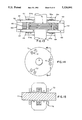
- FIG. 7 is an end view of an arrangement for actively controlling torsional and oscillatory vibrations of a rotary shaft using an inertia ring, magnetic bearings, and actuators of the FIG. 1 type;
- FIGS. 7a and 7b are enlarged views of the encircled details A and B, respectively, in FIG. 7;
- FIG. 8 is a section taken along lines 8--8 in FIG. 7, but with/the rotary shaft shown in partial side elevation;
- FIG. 9 is a diagrammatic depiction of the principal elements of a system for controlling radial shaft vibration
- FIG. 10 is a schematic depiction of an embodiment of the FIG. 9 system
- FIGS. 11 and 12 illustrate a two-axis embodiment of a linear bidirectional variable reluctance actuator for use in the FIG. 10 system in top and front views, respectively;
- FIG. 13 is a view similar to FIG. 11, but showing the actuator in use with respect to a rotary shaft;
- FIGS. 14 and 15 are top and sectional views, respectively, (FIG. 15 being taken along line 15--15 of FIG. 14) of a magnetic alternative to the hydrostatic bearings used for floating the reaction mass in the FIG. 10 system;
- FIG. 16 is a schematic depiction of a steam turbine with a steam supply pipe carrying an active pipe vibration attenuator in accordance with the present invention
- FIG. 17 is a sectional view taken along line 17--17 of FIG. 16 showing an active pipe vibration attenuator on the steam pipe;
- FIG. 18 is a sectional view taken along line 18--18 of FIG. 17;
- FIGS. 18a and 18b are force diagrams depicting the forces applied by the actuators of vibration attenuator of FIGS. 16-18;
- FIG. 19 is a general block diagram of an active vibration attenuator system for pipe vibration attenuation.
- a basic approach to blocking of the transmission of vibration along a path from a structural member is to apply a force to the structural member.
- a bidirectional, variable reluctance force actuator designated generally by the reference numeral 1 in FIG. 1 has been developed for this purpose.
- the actuator 1 is designed for applying a force to the structural member to cancel out the vibration caused by the machinery forces, and in accordance with the present invention, is comprised of a pair of electromagnets 3, 5 which act in opposite directions upon an armature 6. These components are preferably made of laminated iron to eliminate eddy current effects.
- the pair of magnets 3, 5 are mechanically connected together by an external structure which is not shown in FIG. 1, and as will become apparent, varies depending on the nature of the structural member and of the forces to be cancelled.
- the electromagnets 3, 5 will be treated as being vertically oriented so that magnet 3 is the upper electromagnet and magnet 5 is the lower electromagnet, with the subscripts u and d being used to designate the variables associated with the upper and lower magnets, respectively.
- the electromagnets 3, 5 need not be vertically oriented, and can be horizontally or obliquely oriented as appropriate to oppose the pulsations of the structure upon which the actuator 1 is to act.
- the flux ⁇ produced by the coil will be a function of the number of turns and the current i flowing through the coil. This flux is responsible for a magnetic force f being produced which always acts in a direction to reduce the air gap x. Furthermore, given the relationship of magnetic force to coil current and air gap, as well as for the self-inductance of a coil and flux linkage as with the coil of an electromagnet, it can be shown that the magnetic actuator force f can be expressed by the following relationship:
- K is a constant which equals the product of the self-inductance of the coil and the size of air gap x.
- the constant K can be measured or calculated.
- an armature may be used that is of the same physical size as would be used for a unidirectional, variable reluctance force actuator. Additionally, since equation [1] applies relative to the force f u produced by electromagnet 3 and the force f d produced by electromagnet 5, the net force F u acting upon armature 6 can be expressed as:
- a quiescent operating value of ⁇ u and ⁇ d is defined as ⁇
- the variation from the quiescent value is ⁇ such that ⁇ is added to ⁇ to obtain ⁇ u and subtracted from ⁇ to obtain ⁇ d , then:
- a flux linkage control system 10 which is suitable for this purpose is shown in FIG. 3 and is based upon the fact that the flux linkage equals the product of the current, i, and the self-inductance of the coil, L, and that the self-inductance of the coil is equal to K divided by the air gap x, i.e., that
- the coil current i and the air gap x can be easily measured and used to calculate the flux linkages ⁇ via the divider 11. Furthermore, since each electromagnet 3, 5 is driven by a voltage source with a voltage e and the integral of voltage is the flux linkage, the flux linkage divided by the inductance yields the current i. These operations are represented inside of box 13 and are carried out by the electromagnet itself. The calculated flux linkages ⁇ are subtracted from the reference value ⁇ * to produce a flux linkage error ( ⁇ *- ⁇ ) which is amplified by the gain ⁇ of error amplifier 12 to yield the coil reactive voltage, e.
- the coil resistance is not significant and need not be taken into consideration. However, if desired, in order to compensate for coil resistance, the iR drop can be calculated and added to the voltage applied to the coil.
- the transfer function of the flux linkage controller is the transfer function of the flux linkage controller.
- the bandwidth is the gain ⁇ which, at least in principle, can be made as large as desired, and S is the Laplace transform integral variable.
- the control system of FIG. 3 is applied to each of the upper and lower magnets 3, 5 with the upper electromagnet being driven by the signal ⁇ - ⁇ , as the lower electromagnet being driven by ⁇ - ⁇ , as depicted in FIG. 4, where 10a and 10b are the FIG. 3 flux linkage control systems of the upper and lower magnets, and where block 14 containing the transfer function ⁇ /(S+ ⁇ ) incorporates components 11-13 of FIG. 3.
- the output of the flux linkage controllers 10a and 10b are ⁇ u and ⁇ d .
- the signals ⁇ u and ⁇ d are squared and the net force f n calculated in accordance with equation [2]. This calculated value of the net force f n is subtracted from the reference force f n * to produce a force error which is then multiplied by the amplifier gain G of force error amplifier 15 to yield the ⁇ signal.
- the force control system of FIG. 4 can be represented by the block diagram shown in FIG. 5. Also, it can then be determined that the force control has a simple time delay with a time constant T that can be represented as follows:
- variable reluctance actuator The manner in which the voltage and current requirements of the power amplifier are utilized to drive the variable reluctance actuator depends on the actual design and by adjusting the number of coil turns N, any voltage and current desired can be achieved subject to the design constraint reflected by the relationship
- E is the maximum value of the voltage induced in the electromagnet coil
- I is the maximum value of the respective current i u , i d
- x m is the maximum value of the air gap x u , x d
- values for the F and w are obtained from the equation for the force f n where the net force to be produced for offsetting the vibration is
- the actuator of FIG. 1 can function in a linear bidirectional manner by equipping each electromagnet with a flux linkage control system 10 which slaves the flux linkages to a reference signal and drives its respective electromagnet coil with a controlled voltage source.
- the flux linkage control systems are incorporated into a force control system which changes the flux linkages ⁇ in the electromagnet coils so as to produce a linear relationship between the net force f n on the armature structure and a reference force f n *.
- the net actuator force will not vary with the armature position or armature velocity.
- the actuators are utilized to reduce the translational and angular vibration of the structure to zero at a particular point, thereby blocking vibration transmission through the structure. Additionally, this active adaptive vibration cancellation control can also be used to reduce the vibration of an entire structure by applying the disclosed actuators to multiple points on the structure simultaneously. Furthermore, the system of actuators and their control can also be used to provide active damping of a structure simultaneously with the active vibration cancellation to thereby increase the attenuation at the system resonances.
- a first example of an active vibration control system, 20, in accordance with the present invention, represented in FIG. 6, is for canceling propeller induced thrust pulsations on the main drive shaft 23, which are principally resisted by thrust bearing 21 and which result in the hull of the ship being excited to vibratory motion.
- a thrust collar 27 in the form of a disk is rigidly attached to the shaft and functions as the armature of the actuator 25.
- a common armature works with a pair of electromagnets and, in this case, the pair of magnets 25a, 25b are provided which work in opposite directions with respect to the thrust collar 27 which serves as a common armature of the bidirectional variable reluctance force actuator 25.
- Each of the electromagnets 25a, 25b takes the form of a right circular cylinder, and has an annular groove 26 which accommodates the excitation winding.
- a relatively thick-walled cylindrical tube 25c formed of non-magnetic material connects the electromagnets 25a, 25b together into a magnet assembly, and the entire magnet assembly is suspended on the shaft by hydrostatic bearings so that it does not rotate with the shaft.
- a magnet assembly having a mass of 1000 pounds and outside diameter of about 30 inches with an axial length of 15 inches can be used on a conventional propeller shaft and would require the ability for the magnet mass to travel a distance of ⁇ 0.030 inches.
- the system 20 Since the system 20 must cause the force actuator to produce a force equal and opposite to the thrust pulsations to eliminate shaft vibration, some means must be provided to determine what force is to be applied by the force actuator 25. This can be done by considering each harmonic of the thrust pulsations separately and determining how to cancel a single harmonic force component. This can be done by considering that the harmonic has an angular frequency w which is some multiple of shaft speed. As a result of this fact, the pulse train which comes from the pulse tachometer 24 (by appropriate digital signal processing) can be used to generate the functions cos wt and sin wt. The cosine and sine functions, thus, generated can be used to command an actuator force of the form
- an inertia ring 30 is coupled to the shaft 23 by means of variable reluctance torque actuators and magnetic bearings.
- a bearing ring 32 is attached to the shaft 23 by means of a disk 34, which disk could be the end disk of a sound isolation coupling of the type found in an actual propeller shaft installation.
- the outside of bearing ring 32 is a smooth, cylindrical surface 33, relative to which the inertia ring 32 is floated by means of at least four variable reluctance magnetic actuators 36 that are uniformly spaced about the periphery of bearing ring 32. Actuators 36 are serve as magnetic bearings.
- Diametrically opposite units work in opposition and provide the exact net force required to counteract the effect of gravity as the disk and inertia ring rotate with the shaft.
- these magnetic bearings form thrust bearings that prevent axially displacement of the inertia ring.
- Magnetic bearings of conventional design can be used as these magnetic actuators 36, or hydrostatic or pneumatic bearings may be used to suspend the inertia ring 30 in a frictionless manner.
- variable reluctance torque actuators 35 shown in FIGS. 7 and 8, and in greater detail in FIG. 7a produce a torque vector which is coincident with the axis of the shaft so as to apply a torsional vibration-cancelling torque to the shaft. Furthermore, the torque applied to the shaft is also applied to the inertia ring, thereby superimposing an oscillatory angular velocity on the steady-state angular velocity of the inertia ring.
- a low-bandwidth angular position system is provided to control the torque actuators 35 to maintain the average angular position of the inertia ring relative to the disk at a fixed value by acting to maintain the average armature position midway btween the two electomagnetic poles. This causes the inertia ring to rotate with the shaft.
- a differential transformer could be used to obtain a position signal.
- a differential transformer 37 can be disposed between the inertia ring 30 and the bearing ring 32.
- This transformer is excited with a high frequency voltage e 1 at, e.g., 20 KHZ.
- the voltage e 0 will be a suppressed carrier signal whose amplitude will depend on the relative displacement between the two cores (i.e., the angular displacement of the inertia ring).
- the voltage e 0 would be demodulated with the resulting output signal, which will be proportional to the inertia ring displacement angle.
- a torque pulsation canceller of the type shown in FIGS. 7 and 8 would require an inertia ring mass of about 1000 pounds to cancel blade torque pulsations if the ring diameter is 100 inches and the air gap of the actuators is approximately 3/8", although the air gap could be reduced if the ring mass was heavier. Furthermore, since the torque pulsation amplitude is proportional to shaft speed squared, the required gap is constant over the entire speed range.
- the means for determining the cancelling torque which is required is the same as that described relative to the active control of longitudinal shaft vibrations of FIG. 6 but, in this case, the accelerometer is mounted to the shaft. Also, by commanding a torque which is proportional to the vibratory disk velocity, torsional damping can be added to the active torque pulsation cancellation.
- each blade When a propeller rotates, each blade has a resultant force acting on it which has a time-varying component as well as an average value; however, because of the symmetry of the propeller, the resultant lateral force acting on the propeller tends to be zero. Should this not be exactly the case, some alternating lateral force will be applied to the propeller which is ultimately resisted by the stern tube and other journal bearings on the shaft.
- the bull gear on its associated low-speed pinions produce high frequency lateral forces which, to some extent, travel through the sound isolation coupling and excite lateral vibrations of the main shaft.
- FIG. 9 the principal elements of a system for cancelling out lateral vibration forces is schematically depicted.
- the horizontal and vertical directions must be considered separately.
- a force actuator that produces a force f h is provided between the bearing housing and a mass M which is supported in a frictionless manner for treating components in a horizontal direction, and a similar arrangement is provided for treating the vertical forces f v .
- a control scheme of the type described above relative to FIG. 6 for cancelling shaft thrust pulsations can be utilized to null out vibratory motion of the bearing housing in both the horizontal and vertical directions.
- FIG. 10 represents an embodiment of a force cancelling apparatus for this purpose.
- cancelling apparatus 40 comprises a mass which is supported by hydrostatic bearings within a cylinder 41 that is mounted to the bearing housing 42.
- the bearings float the mass on a film of oil and are virtually friction free and can be designed to withstand shock.
- a pair of variable reluctance force actuators 45 are used which work in opposite directions.
- the armatures 46 for the actuators are attached to the mass while the electromagnets 47 are attached to the top and bottom plate 48, 49, respectively, of the unit 40.
- An accelerometer 44 is mounted on top plate 48 and provides a signal for the force-canceling control system. It is noted that while a magnetic suspension system could be used instead of hydrostatic bearings to guide the reaction mass, such is not preferred since it would be more complicated.
- the associated force control system has a low bandwidth mass-centering system which maintains the average position of the mass in its mid position.
- the unit is able to operate in any orientation relative to the gravitational direction and the actuators 45 are controlled in accordance with the principles described above.
- the active force control unit 40 of FIG. 10 is suitable for a number of other applications including the cancellation of rotor imbalance forces by applying such units to the bearing housings, and the cancellation of main propulsion subbase vibration by mounting a number of such units on the subbase. Furthermore, such units 40 can be mounted directly on a hull or other similar structures to cancel vibratory excitation forces.
- FIGS. 11 and 12 show a two-axis active force unit 50 which can be utilized when vibrations must be simultaneously cancelled in two directions.
- a cylindrical armature 51 is clamped between cylindrical members 52 and together form reaction mass M.
- This reaction mass is floated between end members 53 by hydrostatic bearings that are formed by generally circularly shaped pockets 54 (at least three of which are symmetrically disposed about the axis of unit 50) and are fed with oil that flows through metering orifices 55 by a constant pressure hydraulic power supply (not shown).
- the oil which flows through the metering orifices ultimately flows radially outward through a narrow gap that exists between the members 52 and 53, and then out through drain openings 56.
- this bearing system is designed so that the reaction mass M is completely free to move in a plane perpendicular to the axis of cylindrical mass M without such motion being resisted by the hydraulic forces.
- the electromagnets 58 have a laminated structure similar to the stator of an induction motor.
- the laminations of electromagnet 58 are clamped together and secured inside of the cylindrical housing 59 which is rigidly attached to the end members 53.
- the electromagnet windings 58a are placed in slots which are uniformly distributed around the periphery of the electromagnets, as shown for the actuator in FIG. 12; for purposes of simplicity, the electromagnet windings are only schematically depicted. In particular, four independent windings designated B1, B2, C1, and C2, are represented in FIG. 12.
- the windings B1 and B2 produce a force along the x axis which may be either positive or negative, while windings C1 and C2 produce a corresponding bidirectional force along the Y axis.
- Current in the B1 winding produces flux ⁇ B1
- current in the B2 winding produces a flux ⁇ B2 .
- the flux ⁇ B1 will pull the armature in the +x direction
- the flux ⁇ B2 will pull the armature in the -x direction.
- force in the +y and -y direction are controllable by regulation of the fluxes ⁇ C1 and ⁇ C2 . Control of these fluxes is achieved in the manner described above relative to the bidirectional variable reluctance actuators 1.
- element 58 is the electromagnet and element 51 is the armature, as reflected in the embodiment of FIGS. 13 and 14, it may be desirable to reverse this arrangement so that the reaction mass is on the outside and the base (the part attached to the structure) is on the inside.
- Such a unit is particularly useful when the forces are desired to be applied perpendicularly to the axis of a cylindrical-type structure, such as shaft S in FIG. 13.
- a stack of lamination disks 61 are mounted on shaft S for forming either the electromagnet or the armature of the actuator.
- the reaction mass 60 comprises a hollow right-circular cylinder 62, to the opposite ends of which a pair of cylindrical disk members 63 are fixed.
- a lamination disks 65 is attached to the inside of cylinder 62 and forms the armature if laminations 61 form the electromagnet and visa versa.
- the reaction mass 60 is floated by hydrostatic bearings which determine its axial position.
- the hydrostatic bearings have hydrostatic bearing pockets 64a which are formed in disks 64 that are attached to the shaft S and are supplied with oil through metering orifices which are not shown in FIG. 13, but which correspond to orifices 55 shown in FIG. 11. However, if the presence of oil is not acceptable, magnetic or pneumatic levitation may be utilized instead.
- FIGS. 14 and 15 A practical approach for magnetic levitation is depicted in FIGS. 14 and 15.
- three electromagnetic actuators 70 are equiangularly spaced around reaction mass 71, and are disposed on both sides of the reaction mass, as apparent from FIG. 15.
- three of the actuators 70 pull in one direction and the other three of the actuators 70 pull in an opposite direction, e.g., up and down, respectively.
- the line of action of corresponding actuators is coincident and each opposing actuator pair forms a bidirectional force source which maintains the position of the reaction mass midway between the electromagnets by being controlled in the manner described relative to the bidirectional variable reluctance actuator 1.
- the armatures for the electromagnets may be built into the reaction mass 71, or they can be mounted to it in any of the manners described above.
- a vibration control unit 73 of actuators in accordance with the present invention can be utilized to apply suitable forces and moments to a section of the steam pipe so as to cause the pipe at a given cross section to stand still.
- armatures of variable reluctance actuators (which form force sources) are attached to the reaction mass M, axial actuator armatures 77 being shown attached to the inside of end plate 76 in FIG. 18.
- the corresponding electromagnets 79 are connected to the outside of the pipe P via a structural member, such as magnet support 80 mounted upon a pipe clamp ring 81.
- axial actuators 79 serve as force sources for producing forces in the Y direction. While only one such actuator 79 is shown in FIG. 18, three additional pairs of axial force actuators 79 serve to produce a bidirectional force at 90°, 180°, and 270° relative to the axial bidirectional actuator pair formed by armatures 77 and magnets 79. If the Y directed bidirectional forces produced by these actuators are designated f y (1), f y (2), f y (3), and f y (4) (see, FIG. 18a), then the Y-direction force is:
- the torque in the x direction is:
- a pair of tangential actuators 85 each of which has a pair of tangential actuator magnets 86 and a tangential actuator armature 87 are attached to the pipe clamp ring 81 at 90° intervals along with the axial actuators.
- These actuators 86 apply tangential forces, f t (1), f t (2), f t (3), and f t (4) (see, FIG. 18b) and these forces can be used to produce a moment on the pipe int he y direction and the forces in the x and z direction.
- a position control system must be provided which will produce a restoring force proportional to the translation in any of the three coordinate directions x, y and z, as well as a restoring torque to counteract rotation about any of the three axes.
- six position control systems are required, three translational and three angular.
- Position errors can be determined from proximity transducers which measure the position of the reaction mass relative to the pipe.
- each system is provided with a proportional control to provide stiffness, rate control to provide damping, and integral control to provide zero steady-state error.
- the bandwidth of the position control must be kept very low, e.g., 1 Hz, to permit free motion of the reaction mass within the vibratory frequency range of interest.
- the vibratory motion of the pipe has six components which can be deduced by a linear combination of acceleration signals. By integrating the acceleration signals, the three linear velocity components and the angular velocity components can be found. For each velocity component, a corresponding force or torque that will reduce that component to zero is then determined in a manner similar to that described above for longitudinal shaft vibration control. In this manner, the pipe can be made to stand still at the location at which the vibration attenuator is mounted with the reaction mass vibrating in response to the forces applied to make the pipe stand still.
- eight axial and tangential accelerometers would be mounted on the pipe clamp ring and eight proximity transducers provided for measuring the relative axial and tangential displacements between the pipe and the reaction mass comprised of the outer ring, end plates and armatures.
- the pipe vibration attenuator represents the most general system since it involves all six degrees of freedom of the reaction mass and the pipe, relative to which the preceding described examples can be considered special cases of the pipe vibration attenuator which have fewer degrees of freedom.
- a general block diagram for all of the systems and all of the features for cancelling discrete vibration frequencies, including blade rate, turbine rotational, low-speed mesh, and their harmonics can be seen in FIG. 19.
- reaction mass which may have as many as six degrees of freedom.
- the reaction mass is generally levitated or floated in free space by a magnetic suspension, but in some cases, as has already been mentioned, it may be floated by a hydrostatic or pneumatic bearing system.
- the forces between the structure to be silenced and the reaction mass are generated, in each case, by bidirectional variable reluctance force actuators in accordance with the present invention which are given the characteristics of force sources by an appropriate force control system.
- the reaction mass is positioned relative to the structure by means of a low-bandwidth quiescent position controller 91 which prevents the reaction mass from drifting into its mechanical stops while at the same time giving it perfect freedom of motion at the vibration frequencies.
- Integrating accelerometers 92 are used to measure the velocity of the structure in as many degrees of freedom as appropriate for the particular physical system. These velocity signals may be used to supply active damping, which may be necessary to stabilize the nulling system at frequencies corresponding to the poles of the structure transfer function (i.e., at the resonant frequencies).
- a pulse generator 93 For vibration which is driven at the blade rate frequencies and harmonics thereof, a pulse generator 93 produces pulses which correspond to the rotation angle of the shaft.
- a pulse tachometer attached to the shaft is a known means for generating such a pulse train. The angular resolution may be increased by using a phase-locked loop with frequency-division in the feedback path.
- a sine-cosine generator 94 which can be formed by a microprocessor, can be utilized to produce the sine and cosine of the shaft angle. The frequency of these sine and cosine functions will vary in proportion to the speed of the shaft and, thus, can be used to adapt the system to changes in speed of the machinery.
- the output of the reference force generator is in the form ##EQU3## where a kn and b kn are weighting values, where n corresponds to the various harmonics and the subscript k corresponds to the various vibration velocity signals.
- the nulling system 97 generates the a's and b's.
- the harmonic analyzer 96 produces a real time harmonic analysis of each of the vibration velocity signals. This is done by multiplying the vibration signals by the cos nwt and sin nwt signal from the sine/cosine generator 94 and passing the results through low-pass filters. The result is proportional to the Fourier coefficient. This is done for each harmonic of interest.
- the function of the nulling system 97 is to reduce all Fourier coefficients to zero by determining the proper weighting coefficients, which are supplied to the reference force generator 95. As already mentioned, this is analagous to balancing an a-c bridge where one has two knobs to turn to null the output of a detector, the weighing coefficient corresponding to the knobs, the detector output corresponding to the harmonic amplitude which is determined by the harmonic analyzer 96, and the balancing being achieved by a computer instead of manual turning of knobs.
- FIG. 19 is a more generic depiction of the controls of the preceding embodiments. More specifically, the force controller 98 contains both the force controller of FIG. 4 and the flux linkage controller of FIG. 3, one of these controllers being required for each variable reluctance actuator used to control vibration.
- the quiescent position controller 91 positions the reaction mass, and is present in all cases, even though not specifically illustrated in FIG. 6.
- the adaptive control and signal processor 28 of FIG. 6 includes the controls designated 93 through 97 in FIG. 19.
- the active damping block 99 represents an optional feature, wherreby the damping of a mechanical system is increase by commanding a force to be applied in opposition to (i.e., reduce) the velocity of the vibrational movement.
- the present invention provides a system in which the transmission of vibrations to a structure can be blocked by applying forces and/or moments to the structure so as to cancel its vibratory velocity.
- the system can utilize magnetic forces, hydrostatic or pneumatic bearings or guide springs to levitate the reaction mass, and force actuators, in the form of the bidirectional variable reluctance force actuators in accordance with the present invention, to apply forces between the structure and the reaction mass.
- force actuators serve as force sources that have no significant mechanical impedence.
- a force reference generator commands forces to be applied to the structure, via the force sources, utilizing an adaptive control system which determines the proper forces that will cancel the vibration of the structure, being synchronized to machine speed, and determining the harmonic amplitude of the vibration in real time, generating sine and cosine harmonic functions, and automatically nulling out each harmonic of the vibration structure.
- the system in accordance with the present invention is able to cancel up to six degrees of freedom of structure motion and will damp each degree of freedom of structure motion.
Abstract
Description
f=λ.sup.2 /(2K) [1]
f.sub.n =f.sub.u -f.sub.d =(λ.sub.u.sup.2 -λ.sub.d.sup.2)/(2K)[2]
λ.sub.u =λ+Δλ [2.1]
λ.sub.d =λ-Δλ [2.2]
f.sub.u =(1/2K)(λ+Δλ).sup.2 [ 2.3]
f.sub.d =(1/2K)(λ+Δλ).sup.2 [ 2.4]
f.sub.n =(2/K)4Δλ [3]
λ=L i=(K/x)i [4]
(λ/λ*)=Ω/(S+Ω) [5]
T=K/(ΩG2λ) [6]
EI=Fwx.sub.m [7]
f.sub.n =Fcos (wt+φ) [8]
a cos wt+b sin wt [9]
F.sub.y =f.sub.y (1)+f.sub.y (2)+f.sub.y (3)+f.sub.y (4) [11]
M.sub.x =r[f.sub.y (4)-f.sub.y (2)] [12]
M.sub.z =r[f.sub.y (3)-f.sub.y (1)] [13]
Claims (44)
a.sub.kn cos nwt+b.sub.kn sin nwt
a.sub.kn cos nwt+b.sub.kn sin nwt
Priority Applications (1)
| Application Number | Priority Date | Filing Date | Title |
|---|---|---|---|
| US07/666,775 US5126641A (en) | 1991-03-08 | 1991-03-08 | Bidirectional variable reluctance actuator and system for active attenuation of vibration and structure borne noise utilizing same |
Applications Claiming Priority (1)
| Application Number | Priority Date | Filing Date | Title |
|---|---|---|---|
| US07/666,775 US5126641A (en) | 1991-03-08 | 1991-03-08 | Bidirectional variable reluctance actuator and system for active attenuation of vibration and structure borne noise utilizing same |
Publications (1)
| Publication Number | Publication Date |
|---|---|
| US5126641A true US5126641A (en) | 1992-06-30 |
Family
ID=24675421
Family Applications (1)
| Application Number | Title | Priority Date | Filing Date |
|---|---|---|---|
| US07/666,775 Expired - Lifetime US5126641A (en) | 1991-03-08 | 1991-03-08 | Bidirectional variable reluctance actuator and system for active attenuation of vibration and structure borne noise utilizing same |
Country Status (1)
| Country | Link |
|---|---|
| US (1) | US5126641A (en) |
Cited By (48)
| Publication number | Priority date | Publication date | Assignee | Title |
|---|---|---|---|---|
| EP0580202A1 (en) * | 1992-07-23 | 1994-01-26 | The Glacier Metal Company Limited | Magnetic bearing back-up |
| US5350982A (en) * | 1992-12-16 | 1994-09-27 | Seib James N | Motorized golf bag cart circuit and apparatus |
| US5442593A (en) * | 1993-04-16 | 1995-08-15 | The Charles Stark Draper Laboratory, Inc. | Apparatus and method of nulling discrete frequency noise signals |
| US5444346A (en) * | 1992-01-09 | 1995-08-22 | Nissan Motor Co., Ltd. | Control system for actuator applicable to servo system having low resolution sensor and in feedback control mode |
| US5502650A (en) * | 1992-04-01 | 1996-03-26 | Kabushiki Kaisha Toshiba | Apparatus for adjusting rotor |
| US5545957A (en) * | 1993-01-21 | 1996-08-13 | Hitachi, Ltd. | Motor speed controller for suppressing shaft torsion vibration |
| WO1997008477A2 (en) * | 1995-08-31 | 1997-03-06 | Isad Electronic Systems Gmbh & Co.Kg | System for actively reducing radial vibrations in a rotating shaft, and method of operating the system to achieve this |
| US5682069A (en) * | 1994-08-30 | 1997-10-28 | Harris Corporation | Concentrically mounted vibration attenuator and method |
| US5742145A (en) * | 1994-09-07 | 1998-04-21 | Polytechnic University | Apparatus for reducing vibration inputs to a device and/or for positioning the device |
| FR2764691A1 (en) * | 1997-06-12 | 1998-12-18 | Ensmse | Differential torque measuring device |
| US5886493A (en) * | 1995-02-16 | 1999-03-23 | The Kansai Electric Power Co., Inc. | Synchronous machine excitation control device for absorbing harmonics superposed onto fundamental current |
| US6107760A (en) * | 1997-04-07 | 2000-08-22 | Lee; Sang-Yoon | Non-stop variable AC motor |
| US6148784A (en) * | 1995-08-31 | 2000-11-21 | Isad Electronic Systems Gmbh & Co. Kg | Drive systems, especially for a motor vehicle, and method of operating same |
| US6149544A (en) * | 1995-08-31 | 2000-11-21 | Isad Electronic Systems Gmbh & Co. Kg | Drive system for a motor vehicle with a drive unit and electric machine, and method of operating the system |
| US6154000A (en) * | 1994-09-07 | 2000-11-28 | Omnitek Research & Development, Inc. | Apparatus for providing a controlled deflection and/or actuator apparatus |
| US6158405A (en) * | 1995-08-31 | 2000-12-12 | Isad Electronic Systems | System for actively reducing rotational nonuniformity of a shaft, in particular, the drive shaft of an internal combustion engine, and method of operating the system |
| US6177734B1 (en) | 1998-02-27 | 2001-01-23 | Isad Electronic Systems Gmbh & Co. Kg | Starter/generator for an internal combustion engine, especially an engine of a motor vehicle |
| US6199650B1 (en) | 1995-08-31 | 2001-03-13 | Isad Electronic Systems Gmbh & Co. Kg | Drive system, especially for a motor vehicle, and method of operating same |
| US6202776B1 (en) | 1995-08-31 | 2001-03-20 | Isad Electronic Systems Gmbh & Co. Kg | Drive system, especially for a motor vehicle, and method of operating same |
| US6225767B1 (en) * | 1998-06-02 | 2001-05-01 | Emerson Electric Co. | Trajectory controller |
| US6281646B1 (en) | 1995-08-31 | 2001-08-28 | Isad Electronic Systems Gmbh & Co. Kg | Drive system with drive-motor, electric machine and battery |
| US6323614B1 (en) * | 1998-09-04 | 2001-11-27 | The Texas A&M University System | System and method for controlling suspension using a magnetic field |
| US6404154B2 (en) * | 1998-06-02 | 2002-06-11 | Emerson Electric Co. | Force control system |
| US6405701B1 (en) | 1995-08-31 | 2002-06-18 | Isad Electronic Systems Gmbh & Co. Kg | System for actively reducing rotational nonuniformity of a shaft, in particular, the drive shaft of an internal combustion engine, and method for this |
| WO2002058948A1 (en) * | 2001-01-26 | 2002-08-01 | Mts Systems Corporation | Transducer for measuring displacement of a vehicle spindle |
| US6487061B1 (en) | 2000-01-27 | 2002-11-26 | Vssi Commercial, Inc. | Electromagnet support system |
| US6487998B1 (en) | 1995-08-31 | 2002-12-03 | Isad Electronic Systems Gmbh & Co., Kg | Drive system, particularly for a motor vehicle, and process for operating it |
| US6563250B2 (en) | 2001-09-07 | 2003-05-13 | The Boeing Co. | Piezoelectric damping system for reducing noise transmission through structures |
| US20030191600A1 (en) * | 2002-04-03 | 2003-10-09 | Hyde Tristram T. | Method of estimating system dynamics by subsystem transfer function testing |
| US20040066161A1 (en) * | 2000-11-23 | 2004-04-08 | Walter Marx | Active noise compensation |
| US6731083B2 (en) | 1998-06-02 | 2004-05-04 | Switched Reluctance Drives, Ltd. | Flux feedback control system |
| US20040222755A1 (en) * | 2003-05-08 | 2004-11-11 | Borz Fariborzi | Antivibration apparatus and vehicle equipped with such antivibration apparatus |
| US6842717B1 (en) * | 2001-10-16 | 2005-01-11 | Hi-Lex Controls, Inc. | Method and apparatus for evaluating automotive window regulators |
| US20050231143A1 (en) * | 2004-04-14 | 2005-10-20 | Denso Corporation | Method of control of magnetic sound of alternating current rotating machine |
| US20090149999A1 (en) * | 2007-12-11 | 2009-06-11 | Simon Schramm | Gearbox Noise Reduction By Electrical Drive Control |
| WO2010064978A1 (en) * | 2008-12-02 | 2010-06-10 | Lembke Torbjoern | Electrodynamic actuator |
| US20100247335A1 (en) * | 2007-06-15 | 2010-09-30 | Eric Atherton | System for Monitoring an Electrical Submersible Pump |
| ITTO20090389A1 (en) * | 2009-05-22 | 2010-11-23 | Rolls Royce Plc | DEVICE, METHOD AND PROGRAM FOR AUTOMATIC CONTROL COMPUTERS WITH ELECTROMAGNETIC DAMPERS. |
| US20110148113A1 (en) * | 2009-12-17 | 2011-06-23 | Vestas Wind Systems A/S | Vibration damping of wind turbine shaft |
| US8604636B2 (en) * | 2012-04-12 | 2013-12-10 | Kabushiki Kaisha Yaskawa Denki | Power generator |
| US20140054429A1 (en) * | 2012-08-23 | 2014-02-27 | Westinghouse Electric Company Llc | Pipeline clamp for vibration measurement |
| US8676561B2 (en) | 2011-05-23 | 2014-03-18 | I-Shou University | Analysis method for turbine-generator torsional vibrations affected by power transmission system |
| US20150061548A1 (en) * | 2013-08-30 | 2015-03-05 | Alps Electric Co., Ltd. | Vibration generating device |
| US9027873B2 (en) | 2009-02-27 | 2015-05-12 | Textron Innovations Inc. | System and method for vibration control in a rotorcraft using an adaptive reference model algorithm |
| US10372045B2 (en) * | 2012-09-19 | 2019-08-06 | Asml Netherlands B.V. | Method of calibrating a reluctance actuator assembly, reluctance actuator and lithographic apparatus comprising such reluctance actuator |
| US10894590B2 (en) * | 2016-05-18 | 2021-01-19 | Abb Oy | Method and a control arrangement for controlling vibrations of a propulsion unit of a vessel |
| CN114117844A (en) * | 2021-11-08 | 2022-03-01 | 南京交通职业技术学院 | Active damper control method and system of nonlinear structure |
| US11682513B1 (en) | 2021-01-06 | 2023-06-20 | The United States Of America, As Represented By The Secretary Of The Navy | Linearized pull-pull electromagnetic actuators, systems, and methods |
Citations (14)
| Publication number | Priority date | Publication date | Assignee | Title |
|---|---|---|---|---|
| US3800555A (en) * | 1972-10-30 | 1974-04-02 | H Arneson | Vibration attenuation coupling structure |
| US3874818A (en) * | 1972-10-19 | 1975-04-01 | Westland Aircraft Ltd | Bifilar vibration dampers |
| US3988073A (en) * | 1975-04-11 | 1976-10-26 | United Technologies Corporation | Spherical bifilar tuning pin bushing |
| US4097833A (en) * | 1976-02-09 | 1978-06-27 | Ledex, Inc. | Electromagnetic actuator |
| US4237703A (en) * | 1978-10-12 | 1980-12-09 | Caterpillar Tractor Co. | Magnetic governor drive coupling |
| US4282501A (en) * | 1979-08-23 | 1981-08-04 | Ledex, Inc. | Bi-directional linear actuator |
| US4406642A (en) * | 1981-04-13 | 1983-09-27 | Dresser Industries, Inc. | Shaft dampening apparatus |
| US4600863A (en) * | 1982-04-19 | 1986-07-15 | Sound Attenuators Limited | Method of and apparatus for active vibration isolation |
| US4656400A (en) * | 1985-07-08 | 1987-04-07 | Synektron Corporation | Variable reluctance actuators having improved constant force control and position-sensing features |
| US4686404A (en) * | 1984-05-18 | 1987-08-11 | Ntn Toyo Bearing Co., Ltd. | Controlled radial magnetic bearing device |
| US4697128A (en) * | 1985-05-13 | 1987-09-29 | Hitachi, Ltd. | Control apparatus for a rotor supported by an electromagnetic bearing |
| US4808892A (en) * | 1985-12-13 | 1989-02-28 | Kulick And Soffa Ind. Inc. | Bi-directional drive motor system |
| US4947067A (en) * | 1988-04-20 | 1990-08-07 | Societe De Mecanique Magnetique S.A. | Vibrator/dampener having magnetic suspension and servo-control along three axes |
| US4963804A (en) * | 1989-07-10 | 1990-10-16 | Westinghouse Electric Corp. | Apparatus and method for reducing vibration of rotating machinery |
-
1991
- 1991-03-08 US US07/666,775 patent/US5126641A/en not_active Expired - Lifetime
Patent Citations (14)
| Publication number | Priority date | Publication date | Assignee | Title |
|---|---|---|---|---|
| US3874818A (en) * | 1972-10-19 | 1975-04-01 | Westland Aircraft Ltd | Bifilar vibration dampers |
| US3800555A (en) * | 1972-10-30 | 1974-04-02 | H Arneson | Vibration attenuation coupling structure |
| US3988073A (en) * | 1975-04-11 | 1976-10-26 | United Technologies Corporation | Spherical bifilar tuning pin bushing |
| US4097833A (en) * | 1976-02-09 | 1978-06-27 | Ledex, Inc. | Electromagnetic actuator |
| US4237703A (en) * | 1978-10-12 | 1980-12-09 | Caterpillar Tractor Co. | Magnetic governor drive coupling |
| US4282501A (en) * | 1979-08-23 | 1981-08-04 | Ledex, Inc. | Bi-directional linear actuator |
| US4406642A (en) * | 1981-04-13 | 1983-09-27 | Dresser Industries, Inc. | Shaft dampening apparatus |
| US4600863A (en) * | 1982-04-19 | 1986-07-15 | Sound Attenuators Limited | Method of and apparatus for active vibration isolation |
| US4686404A (en) * | 1984-05-18 | 1987-08-11 | Ntn Toyo Bearing Co., Ltd. | Controlled radial magnetic bearing device |
| US4697128A (en) * | 1985-05-13 | 1987-09-29 | Hitachi, Ltd. | Control apparatus for a rotor supported by an electromagnetic bearing |
| US4656400A (en) * | 1985-07-08 | 1987-04-07 | Synektron Corporation | Variable reluctance actuators having improved constant force control and position-sensing features |
| US4808892A (en) * | 1985-12-13 | 1989-02-28 | Kulick And Soffa Ind. Inc. | Bi-directional drive motor system |
| US4947067A (en) * | 1988-04-20 | 1990-08-07 | Societe De Mecanique Magnetique S.A. | Vibrator/dampener having magnetic suspension and servo-control along three axes |
| US4963804A (en) * | 1989-07-10 | 1990-10-16 | Westinghouse Electric Corp. | Apparatus and method for reducing vibration of rotating machinery |
Cited By (66)
| Publication number | Priority date | Publication date | Assignee | Title |
|---|---|---|---|---|
| US5444346A (en) * | 1992-01-09 | 1995-08-22 | Nissan Motor Co., Ltd. | Control system for actuator applicable to servo system having low resolution sensor and in feedback control mode |
| US5502650A (en) * | 1992-04-01 | 1996-03-26 | Kabushiki Kaisha Toshiba | Apparatus for adjusting rotor |
| US5345127A (en) * | 1992-07-23 | 1994-09-06 | The Glacier Metal Company Limited | Magnetic bearing back-up |
| EP0580202A1 (en) * | 1992-07-23 | 1994-01-26 | The Glacier Metal Company Limited | Magnetic bearing back-up |
| US5350982A (en) * | 1992-12-16 | 1994-09-27 | Seib James N | Motorized golf bag cart circuit and apparatus |
| US5545957A (en) * | 1993-01-21 | 1996-08-13 | Hitachi, Ltd. | Motor speed controller for suppressing shaft torsion vibration |
| US5442593A (en) * | 1993-04-16 | 1995-08-15 | The Charles Stark Draper Laboratory, Inc. | Apparatus and method of nulling discrete frequency noise signals |
| US5682069A (en) * | 1994-08-30 | 1997-10-28 | Harris Corporation | Concentrically mounted vibration attenuator and method |
| US6154000A (en) * | 1994-09-07 | 2000-11-28 | Omnitek Research & Development, Inc. | Apparatus for providing a controlled deflection and/or actuator apparatus |
| US5742145A (en) * | 1994-09-07 | 1998-04-21 | Polytechnic University | Apparatus for reducing vibration inputs to a device and/or for positioning the device |
| US5886493A (en) * | 1995-02-16 | 1999-03-23 | The Kansai Electric Power Co., Inc. | Synchronous machine excitation control device for absorbing harmonics superposed onto fundamental current |
| WO1997008477A3 (en) * | 1995-08-31 | 1997-08-14 | Clouth Gummiwerke Ag | System for actively reducing radial vibrations in a rotating shaft, and method of operating the system to achieve this |
| US6281646B1 (en) | 1995-08-31 | 2001-08-28 | Isad Electronic Systems Gmbh & Co. Kg | Drive system with drive-motor, electric machine and battery |
| WO1997008477A2 (en) * | 1995-08-31 | 1997-03-06 | Isad Electronic Systems Gmbh & Co.Kg | System for actively reducing radial vibrations in a rotating shaft, and method of operating the system to achieve this |
| US6148784A (en) * | 1995-08-31 | 2000-11-21 | Isad Electronic Systems Gmbh & Co. Kg | Drive systems, especially for a motor vehicle, and method of operating same |
| US6149544A (en) * | 1995-08-31 | 2000-11-21 | Isad Electronic Systems Gmbh & Co. Kg | Drive system for a motor vehicle with a drive unit and electric machine, and method of operating the system |
| US6487998B1 (en) | 1995-08-31 | 2002-12-03 | Isad Electronic Systems Gmbh & Co., Kg | Drive system, particularly for a motor vehicle, and process for operating it |
| US6158405A (en) * | 1995-08-31 | 2000-12-12 | Isad Electronic Systems | System for actively reducing rotational nonuniformity of a shaft, in particular, the drive shaft of an internal combustion engine, and method of operating the system |
| US6405701B1 (en) | 1995-08-31 | 2002-06-18 | Isad Electronic Systems Gmbh & Co. Kg | System for actively reducing rotational nonuniformity of a shaft, in particular, the drive shaft of an internal combustion engine, and method for this |
| US6199650B1 (en) | 1995-08-31 | 2001-03-13 | Isad Electronic Systems Gmbh & Co. Kg | Drive system, especially for a motor vehicle, and method of operating same |
| US6202776B1 (en) | 1995-08-31 | 2001-03-20 | Isad Electronic Systems Gmbh & Co. Kg | Drive system, especially for a motor vehicle, and method of operating same |
| US6365983B1 (en) | 1995-08-31 | 2002-04-02 | Isad Electronic Systems Gmbh & Co. Kg | Starter/generator for an internal combustion engine, especially an engine of a motor vehicle |
| US6107760A (en) * | 1997-04-07 | 2000-08-22 | Lee; Sang-Yoon | Non-stop variable AC motor |
| FR2764691A1 (en) * | 1997-06-12 | 1998-12-18 | Ensmse | Differential torque measuring device |
| US6177734B1 (en) | 1998-02-27 | 2001-01-23 | Isad Electronic Systems Gmbh & Co. Kg | Starter/generator for an internal combustion engine, especially an engine of a motor vehicle |
| US6225767B1 (en) * | 1998-06-02 | 2001-05-01 | Emerson Electric Co. | Trajectory controller |
| US6404154B2 (en) * | 1998-06-02 | 2002-06-11 | Emerson Electric Co. | Force control system |
| US6731083B2 (en) | 1998-06-02 | 2004-05-04 | Switched Reluctance Drives, Ltd. | Flux feedback control system |
| US6323614B1 (en) * | 1998-09-04 | 2001-11-27 | The Texas A&M University System | System and method for controlling suspension using a magnetic field |
| US6487061B1 (en) | 2000-01-27 | 2002-11-26 | Vssi Commercial, Inc. | Electromagnet support system |
| US7064503B2 (en) * | 2000-11-23 | 2006-06-20 | Siemens Aktiengesellschaft | Active noise compensation |
| US20040066161A1 (en) * | 2000-11-23 | 2004-04-08 | Walter Marx | Active noise compensation |
| US6575031B2 (en) | 2001-01-26 | 2003-06-10 | Mts Systems Corporation | Transducer for measuring displacement of a vehicle spindle |
| WO2002058948A1 (en) * | 2001-01-26 | 2002-08-01 | Mts Systems Corporation | Transducer for measuring displacement of a vehicle spindle |
| US6563250B2 (en) | 2001-09-07 | 2003-05-13 | The Boeing Co. | Piezoelectric damping system for reducing noise transmission through structures |
| US6842717B1 (en) * | 2001-10-16 | 2005-01-11 | Hi-Lex Controls, Inc. | Method and apparatus for evaluating automotive window regulators |
| US20050192776A1 (en) * | 2001-10-16 | 2005-09-01 | Palmer Thomas N. | Method and apparatus for evaluating automotive window regulators |
| US7050939B2 (en) | 2001-10-16 | 2006-05-23 | Hi-Lex Controls, Inc. | Method and apparatus for evaluating automotive window regulators |
| US6804615B2 (en) * | 2002-04-03 | 2004-10-12 | Honeywell International Inc. | Method of estimating system dynamics by subsystem transfer function testing |
| US20030191600A1 (en) * | 2002-04-03 | 2003-10-09 | Hyde Tristram T. | Method of estimating system dynamics by subsystem transfer function testing |
| US20040222755A1 (en) * | 2003-05-08 | 2004-11-11 | Borz Fariborzi | Antivibration apparatus and vehicle equipped with such antivibration apparatus |
| US7170247B2 (en) * | 2004-04-14 | 2007-01-30 | Denso Corporation | Method of control of magnetic sound of alternating current rotating machine |
| US20050231143A1 (en) * | 2004-04-14 | 2005-10-20 | Denso Corporation | Method of control of magnetic sound of alternating current rotating machine |
| US20100247335A1 (en) * | 2007-06-15 | 2010-09-30 | Eric Atherton | System for Monitoring an Electrical Submersible Pump |
| US9476425B2 (en) | 2007-06-15 | 2016-10-25 | Baker Hughes Incorporated | Apparatus for monitoring an electrical submersible pump |
| US8602754B2 (en) * | 2007-06-15 | 2013-12-10 | Baker Hughes Incorporated | System for monitoring an electrical submersible pump |
| US20090149999A1 (en) * | 2007-12-11 | 2009-06-11 | Simon Schramm | Gearbox Noise Reduction By Electrical Drive Control |
| CN101493142A (en) * | 2007-12-11 | 2009-07-29 | 通用电气公司 | Gearbox noise reduction by electrical drive control |
| CN101493142B (en) * | 2007-12-11 | 2013-11-27 | 通用电气公司 | Gearbox noise reduction by electrical drive control |
| US8532828B2 (en) * | 2007-12-11 | 2013-09-10 | General Electric Company | Gearbox noise reduction by electrical drive control |
| WO2010064978A1 (en) * | 2008-12-02 | 2010-06-10 | Lembke Torbjoern | Electrodynamic actuator |
| US9027873B2 (en) | 2009-02-27 | 2015-05-12 | Textron Innovations Inc. | System and method for vibration control in a rotorcraft using an adaptive reference model algorithm |
| WO2010133332A1 (en) * | 2009-05-22 | 2010-11-25 | Rolls-Royce Plc | Device, method and program for automatic control computers for electromagnetic dampers |
| ITTO20090389A1 (en) * | 2009-05-22 | 2010-11-23 | Rolls Royce Plc | DEVICE, METHOD AND PROGRAM FOR AUTOMATIC CONTROL COMPUTERS WITH ELECTROMAGNETIC DAMPERS. |
| US20110148113A1 (en) * | 2009-12-17 | 2011-06-23 | Vestas Wind Systems A/S | Vibration damping of wind turbine shaft |
| US8676561B2 (en) | 2011-05-23 | 2014-03-18 | I-Shou University | Analysis method for turbine-generator torsional vibrations affected by power transmission system |
| US8604636B2 (en) * | 2012-04-12 | 2013-12-10 | Kabushiki Kaisha Yaskawa Denki | Power generator |
| US9322492B2 (en) * | 2012-08-23 | 2016-04-26 | Westinghouse Electric Company Llc | Pipeline clamp for vibration measurement |
| US20140054429A1 (en) * | 2012-08-23 | 2014-02-27 | Westinghouse Electric Company Llc | Pipeline clamp for vibration measurement |
| US10372045B2 (en) * | 2012-09-19 | 2019-08-06 | Asml Netherlands B.V. | Method of calibrating a reluctance actuator assembly, reluctance actuator and lithographic apparatus comprising such reluctance actuator |
| US20150061548A1 (en) * | 2013-08-30 | 2015-03-05 | Alps Electric Co., Ltd. | Vibration generating device |
| US9350285B2 (en) * | 2013-08-30 | 2016-05-24 | Alps Electric Co., Ltd. | Vibration generating device |
| US10894590B2 (en) * | 2016-05-18 | 2021-01-19 | Abb Oy | Method and a control arrangement for controlling vibrations of a propulsion unit of a vessel |
| US11682513B1 (en) | 2021-01-06 | 2023-06-20 | The United States Of America, As Represented By The Secretary Of The Navy | Linearized pull-pull electromagnetic actuators, systems, and methods |
| CN114117844A (en) * | 2021-11-08 | 2022-03-01 | 南京交通职业技术学院 | Active damper control method and system of nonlinear structure |
| CN114117844B (en) * | 2021-11-08 | 2022-10-14 | 南京交通职业技术学院 | Active damper control method and system of nonlinear structure |
Similar Documents
| Publication | Publication Date | Title |
|---|---|---|
| US5126641A (en) | Bidirectional variable reluctance actuator and system for active attenuation of vibration and structure borne noise utilizing same | |
| US4935838A (en) | Structural magnetic vibration controller and method for actively controlling vibrations on stationary components of rotary machinery | |
| US4839550A (en) | Controlled type magnetic bearing device | |
| US5202824A (en) | Rotating force generator for magnetic bearings | |
| Hoque et al. | Development of a three-axis active vibration isolator using zero-power control | |
| Ahrens et al. | Performance of a magnetically suspended flywheel energy storage device | |
| US5291975A (en) | System and method for damping narrow band axial vibrations of a rotating device | |
| JPH0418171B2 (en) | ||
| CA1229903A (en) | Method and device for reducing the vibrations of rotating machines equipped with an active magnetic suspension | |
| US4947067A (en) | Vibrator/dampener having magnetic suspension and servo-control along three axes | |
| US4912387A (en) | Adaptive noise cancelling for magnetic bearing auto-balancing | |
| Bleuler et al. | Application of digital signal processors for industrial magnetic bearings | |
| CN109058292A (en) | A kind of novel magnetically levitated direct suppressing method of bearing unbalance vibration power | |
| US5155402A (en) | Bearing radially and axially supporting rotor of large radial dimensions | |
| US5609230A (en) | Vibration cancellation device | |
| GB1601096A (en) | Suspension system | |
| JPH01279116A (en) | Magnetic bearing to which permanent magnet receiving holding power in axial direction is mounted | |
| JPS6014929B2 (en) | Synchronous disturbance compensation device in magnetically suspended rotor | |
| RU2645561C2 (en) | Pneumatic suspension and vibration isolation system employing low friction cable isolators | |
| GB2259158A (en) | Control device for electromagnetic suspension system | |
| JPH0884454A (en) | Damping apparatus for rotary machine | |
| Ueno et al. | Stability of a tilt-controlling axial gap self-bearing motor with single-stator | |
| Boehm et al. | Development of active magnetic bearings for high speed rotors | |
| JPH04229061A (en) | Large amplitude low frequency vibrator | |
| EP0381898A2 (en) | Method and apparatus for cancelling vibrations of rotating machines with active magnetic bearings |
Legal Events
| Date | Code | Title | Description |
|---|---|---|---|
| AS | Assignment |
Owner name: WESTINGHOUSE ELECTRIC CORPORATION, WESTINGHOUSE BU Free format text: ASSIGNMENT OF ASSIGNORS INTEREST.;ASSIGNORS:PUTMAN, THOMAS H.;WRIGHT, DEXTER V.;REEL/FRAME:005641/0221;SIGNING DATES FROM 19910222 TO 19910225 |
|
| STCF | Information on status: patent grant |
Free format text: PATENTED CASE |
|
| FEPP | Fee payment procedure |
Free format text: PAYER NUMBER DE-ASSIGNED (ORIGINAL EVENT CODE: RMPN); ENTITY STATUS OF PATENT OWNER: LARGE ENTITY Free format text: PAYOR NUMBER ASSIGNED (ORIGINAL EVENT CODE: ASPN); ENTITY STATUS OF PATENT OWNER: LARGE ENTITY |
|
| FEPP | Fee payment procedure |
Free format text: PAYOR NUMBER ASSIGNED (ORIGINAL EVENT CODE: ASPN); ENTITY STATUS OF PATENT OWNER: LARGE ENTITY |
|
| FPAY | Fee payment |
Year of fee payment: 4 |
|
| AS | Assignment |
Owner name: WESTINGHOUSE GOVERNMENT SERVICES COMPANY LLC, PENN Free format text: ASSIGNMENT SECURITY AGREEMENT;ASSIGNOR:CBS CORPORATION (F/K/A WESTINGHOUSE ELECTRIC CORPORATION);REEL/FRAME:010121/0391 Effective date: 19990322 |
|
| FPAY | Fee payment |
Year of fee payment: 8 |
|
| FEPP | Fee payment procedure |
Free format text: PAYOR NUMBER ASSIGNED (ORIGINAL EVENT CODE: ASPN); ENTITY STATUS OF PATENT OWNER: LARGE ENTITY Free format text: PAYER NUMBER DE-ASSIGNED (ORIGINAL EVENT CODE: RMPN); ENTITY STATUS OF PATENT OWNER: LARGE ENTITY |
|
| AS | Assignment |
Owner name: CURTISS-WRIGHT ELECTRO-MECHANICAL CORPORATION, PEN Free format text: ASSIGNMENT OF ASSIGNORS INTEREST;ASSIGNOR:WESTINGHOUSE GOVERNMENT SERVICES COMPANY LLC;REEL/FRAME:013645/0956 Effective date: 20021028 |
|
| FPAY | Fee payment |
Year of fee payment: 12 |