EP2650509A2 - A method and system for controlling an extraction pressure and temperature of a stoichiometric EGR system - Google Patents
A method and system for controlling an extraction pressure and temperature of a stoichiometric EGR system Download PDFInfo
- Publication number
- EP2650509A2 EP2650509A2 EP13162849.7A EP13162849A EP2650509A2 EP 2650509 A2 EP2650509 A2 EP 2650509A2 EP 13162849 A EP13162849 A EP 13162849A EP 2650509 A2 EP2650509 A2 EP 2650509A2
- Authority
- EP
- European Patent Office
- Prior art keywords
- compressor
- working fluid
- extraction
- egr
- combustion system
- Prior art date
- Legal status (The legal status is an assumption and is not a legal conclusion. Google has not performed a legal analysis and makes no representation as to the accuracy of the status listed.)
- Withdrawn
Links
- 238000000034 method Methods 0.000 title claims abstract description 37
- 238000000605 extraction Methods 0.000 title claims description 56
- 230000000704 physical effect Effects 0.000 claims abstract description 15
- 239000012530 fluid Substances 0.000 claims description 155
- 238000002485 combustion reaction Methods 0.000 claims description 98
- 239000000446 fuel Substances 0.000 claims description 64
- 239000007800 oxidant agent Substances 0.000 claims description 42
- 230000001590 oxidative effect Effects 0.000 claims description 40
- 238000011144 upstream manufacturing Methods 0.000 claims description 10
- 239000000203 mixture Substances 0.000 claims description 8
- 238000011084 recovery Methods 0.000 claims description 6
- 239000007789 gas Substances 0.000 abstract description 47
- CURLTUGMZLYLDI-UHFFFAOYSA-N Carbon dioxide Chemical compound O=C=O CURLTUGMZLYLDI-UHFFFAOYSA-N 0.000 abstract description 18
- 229910002092 carbon dioxide Inorganic materials 0.000 abstract description 9
- 239000001569 carbon dioxide Substances 0.000 abstract description 9
- XKRFYHLGVUSROY-UHFFFAOYSA-N Argon Chemical compound [Ar] XKRFYHLGVUSROY-UHFFFAOYSA-N 0.000 abstract description 6
- IJGRMHOSHXDMSA-UHFFFAOYSA-N Atomic nitrogen Chemical compound N#N IJGRMHOSHXDMSA-UHFFFAOYSA-N 0.000 abstract description 4
- 229910052786 argon Inorganic materials 0.000 abstract description 3
- 230000008569 process Effects 0.000 description 10
- 239000003570 air Substances 0.000 description 7
- 239000012080 ambient air Substances 0.000 description 6
- QVGXLLKOCUKJST-UHFFFAOYSA-N atomic oxygen Chemical compound [O] QVGXLLKOCUKJST-UHFFFAOYSA-N 0.000 description 6
- 239000001301 oxygen Substances 0.000 description 6
- 229910052760 oxygen Inorganic materials 0.000 description 6
- 238000012986 modification Methods 0.000 description 5
- 230000004048 modification Effects 0.000 description 5
- VNWKTOKETHGBQD-UHFFFAOYSA-N methane Chemical compound C VNWKTOKETHGBQD-UHFFFAOYSA-N 0.000 description 4
- 239000004215 Carbon black (E152) Substances 0.000 description 3
- UGFAIRIUMAVXCW-UHFFFAOYSA-N Carbon monoxide Chemical compound [O+]#[C-] UGFAIRIUMAVXCW-UHFFFAOYSA-N 0.000 description 3
- 230000008901 benefit Effects 0.000 description 3
- 229910002091 carbon monoxide Inorganic materials 0.000 description 3
- 239000003344 environmental pollutant Substances 0.000 description 3
- 229930195733 hydrocarbon Natural products 0.000 description 3
- 150000002430 hydrocarbons Chemical class 0.000 description 3
- 231100000719 pollutant Toxicity 0.000 description 3
- XLYOFNOQVPJJNP-UHFFFAOYSA-N water Substances O XLYOFNOQVPJJNP-UHFFFAOYSA-N 0.000 description 3
- 230000015572 biosynthetic process Effects 0.000 description 2
- 230000008859 change Effects 0.000 description 2
- 230000001276 controlling effect Effects 0.000 description 2
- 239000012809 cooling fluid Substances 0.000 description 2
- 238000013461 design Methods 0.000 description 2
- 238000002955 isolation Methods 0.000 description 2
- 238000004519 manufacturing process Methods 0.000 description 2
- 239000003345 natural gas Substances 0.000 description 2
- 230000009467 reduction Effects 0.000 description 2
- OKTJSMMVPCPJKN-UHFFFAOYSA-N Carbon Chemical compound [C] OKTJSMMVPCPJKN-UHFFFAOYSA-N 0.000 description 1
- 230000006978 adaptation Effects 0.000 description 1
- 239000006227 byproduct Substances 0.000 description 1
- 229910052799 carbon Inorganic materials 0.000 description 1
- 238000011161 development Methods 0.000 description 1
- 230000007613 environmental effect Effects 0.000 description 1
- 239000000463 material Substances 0.000 description 1
- VUZPPFZMUPKLLV-UHFFFAOYSA-N methane;hydrate Chemical compound C.O VUZPPFZMUPKLLV-UHFFFAOYSA-N 0.000 description 1
- 229910052757 nitrogen Inorganic materials 0.000 description 1
- 230000001737 promoting effect Effects 0.000 description 1
- 238000010926 purge Methods 0.000 description 1
- 230000001105 regulatory effect Effects 0.000 description 1
- 230000035939 shock Effects 0.000 description 1
Images


Classifications
-
- F—MECHANICAL ENGINEERING; LIGHTING; HEATING; WEAPONS; BLASTING
- F02—COMBUSTION ENGINES; HOT-GAS OR COMBUSTION-PRODUCT ENGINE PLANTS
- F02C—GAS-TURBINE PLANTS; AIR INTAKES FOR JET-PROPULSION PLANTS; CONTROLLING FUEL SUPPLY IN AIR-BREATHING JET-PROPULSION PLANTS
- F02C3/00—Gas-turbine plants characterised by the use of combustion products as the working fluid
- F02C3/34—Gas-turbine plants characterised by the use of combustion products as the working fluid with recycling of part of the working fluid, i.e. semi-closed cycles with combustion products in the closed part of the cycle
-
- F—MECHANICAL ENGINEERING; LIGHTING; HEATING; WEAPONS; BLASTING
- F01—MACHINES OR ENGINES IN GENERAL; ENGINE PLANTS IN GENERAL; STEAM ENGINES
- F01K—STEAM ENGINE PLANTS; STEAM ACCUMULATORS; ENGINE PLANTS NOT OTHERWISE PROVIDED FOR; ENGINES USING SPECIAL WORKING FLUIDS OR CYCLES
- F01K23/00—Plants characterised by more than one engine delivering power external to the plant, the engines being driven by different fluids
- F01K23/02—Plants characterised by more than one engine delivering power external to the plant, the engines being driven by different fluids the engine cycles being thermally coupled
- F01K23/06—Plants characterised by more than one engine delivering power external to the plant, the engines being driven by different fluids the engine cycles being thermally coupled combustion heat from one cycle heating the fluid in another cycle
- F01K23/10—Plants characterised by more than one engine delivering power external to the plant, the engines being driven by different fluids the engine cycles being thermally coupled combustion heat from one cycle heating the fluid in another cycle with exhaust fluid of one cycle heating the fluid in another cycle
-
- F—MECHANICAL ENGINEERING; LIGHTING; HEATING; WEAPONS; BLASTING
- F02—COMBUSTION ENGINES; HOT-GAS OR COMBUSTION-PRODUCT ENGINE PLANTS
- F02C—GAS-TURBINE PLANTS; AIR INTAKES FOR JET-PROPULSION PLANTS; CONTROLLING FUEL SUPPLY IN AIR-BREATHING JET-PROPULSION PLANTS
- F02C6/00—Plural gas-turbine plants; Combinations of gas-turbine plants with other apparatus; Adaptations of gas-turbine plants for special use
- F02C6/18—Plural gas-turbine plants; Combinations of gas-turbine plants with other apparatus; Adaptations of gas-turbine plants for special use using the waste heat of gas-turbine plants outside the plants themselves, e.g. gas-turbine power heat plants
-
- F—MECHANICAL ENGINEERING; LIGHTING; HEATING; WEAPONS; BLASTING
- F02—COMBUSTION ENGINES; HOT-GAS OR COMBUSTION-PRODUCT ENGINE PLANTS
- F02C—GAS-TURBINE PLANTS; AIR INTAKES FOR JET-PROPULSION PLANTS; CONTROLLING FUEL SUPPLY IN AIR-BREATHING JET-PROPULSION PLANTS
- F02C9/00—Controlling gas-turbine plants; Controlling fuel supply in air- breathing jet-propulsion plants
-
- F—MECHANICAL ENGINEERING; LIGHTING; HEATING; WEAPONS; BLASTING
- F02—COMBUSTION ENGINES; HOT-GAS OR COMBUSTION-PRODUCT ENGINE PLANTS
- F02C—GAS-TURBINE PLANTS; AIR INTAKES FOR JET-PROPULSION PLANTS; CONTROLLING FUEL SUPPLY IN AIR-BREATHING JET-PROPULSION PLANTS
- F02C9/00—Controlling gas-turbine plants; Controlling fuel supply in air- breathing jet-propulsion plants
- F02C9/48—Control of fuel supply conjointly with another control of the plant
- F02C9/50—Control of fuel supply conjointly with another control of the plant with control of working fluid flow
-
- F—MECHANICAL ENGINEERING; LIGHTING; HEATING; WEAPONS; BLASTING
- F05—INDEXING SCHEMES RELATING TO ENGINES OR PUMPS IN VARIOUS SUBCLASSES OF CLASSES F01-F04
- F05D—INDEXING SCHEME FOR ASPECTS RELATING TO NON-POSITIVE-DISPLACEMENT MACHINES OR ENGINES, GAS-TURBINES OR JET-PROPULSION PLANTS
- F05D2220/00—Application
- F05D2220/70—Application in combination with
- F05D2220/72—Application in combination with a steam turbine
-
- Y—GENERAL TAGGING OF NEW TECHNOLOGICAL DEVELOPMENTS; GENERAL TAGGING OF CROSS-SECTIONAL TECHNOLOGIES SPANNING OVER SEVERAL SECTIONS OF THE IPC; TECHNICAL SUBJECTS COVERED BY FORMER USPC CROSS-REFERENCE ART COLLECTIONS [XRACs] AND DIGESTS
- Y02—TECHNOLOGIES OR APPLICATIONS FOR MITIGATION OR ADAPTATION AGAINST CLIMATE CHANGE
- Y02E—REDUCTION OF GREENHOUSE GAS [GHG] EMISSIONS, RELATED TO ENERGY GENERATION, TRANSMISSION OR DISTRIBUTION
- Y02E20/00—Combustion technologies with mitigation potential
- Y02E20/16—Combined cycle power plant [CCPP], or combined cycle gas turbine [CCGT]
Definitions
- the present application relates generally to a combined-cycle powerplant; and more particularly to a system and method for operating a turbomachine incorporated with stoichiometric exhaust gas recirculation (S-EGR).
- S-EGR stoichiometric exhaust gas recirculation
- working fluid a high energy fluid
- the turbine buckets rotate a shaft coupled to the load, such as an electrical generator.
- the shaft rotation induces current in a coil electrically coupled to an external electrical circuit.
- HRSG heat recovery steam generator
- S-EGR is a form of EGR where the combustion process consumes a supplied oxidant.
- the oxidant can include, for example, air or an oxygen source.
- the S-EGR process can be configured to yield an exhaust stream that includes a relatively high concentration of a desirable gas and is substantially oxygen-free.
- This desirable gas includes, but is not limited to: Carbon Dioxide (CO2), Nitrogen (N2), or Argon.
- CO2 Carbon Dioxide
- N2 Nitrogen
- Argon Argon
- a system comprises: an oxidant compressor comprising an ac_inlet and an ac_outlet; a compressor comprising a compressor inlet and a compressor outlet; wherein the compressor operates independently of the oxidant compressor; at least one combustion system that operatively generates a working fluid and comprises a head end and a discharge end, wherein the head end is fluidly connected to: an air stream conduit, the compressor outlet, and wherein the at least one combustion system is connected to a first fuel supply; a primary turbine section operatively connected to the compressor, wherein the turbine section comprises a PT_inlet which receives the working fluid from the at least one combustion system, and a PT_outlet that discharges the working fluid; an exhaust gas recirculation (EGR) system fluidly connected between the discharge of an exhaust section and the compressor inlet, wherein the compressor inlet ingests the working fluid exiting the exhaust section; wherein the EGR system comprises a control device for adjusting a physical property
- a method comprises: operating an oxidant compressor to compress an ingested oxidant; operating a compressor to compress a working fluid, wherein the operation of the oxidant compressor is independent of the operation of the compressor; passing to a primary combustion system: a compressed oxidant, derived from the oxidant compressor, and a compressed working fluid, derived from the compressor; delivering a fuel to the primary combustion system which operatively combusts a mixture of: the fuel, the compressed oxidant and the compressed working fluid; creating the working fluid; passing the working fluid from the primary combustion system to a primary turbine section; operating an EGR system to recirculate the working fluid exiting an exhaust section to flow into an inlet of the compressor; wherein the EGR system comprises a control device for adjusting a physical property of the working fluid; extracting a portion of the working fluid; wherein the working fluid is nearly oxygen-free, and the primary combustion system operates in a substantially stoichiometric manner; and operating the
- FIGS. Various features, aspects, and advantages of the present invention may become better understood when the following detailed description is read with reference to the accompanying figures (FIGS) in which like characters represent like elements/parts throughout the FIGS., and in which:
- first, second, primary, secondary, etc. may be used herein to describe various elements, these elements should not be limited by these terms. These terms are only used to distinguish one element from another. For example, but not limiting to, a first element could be termed a second element, and, similarly, a second element could be termed a first element, without departing from the scope of example embodiments.
- the term "and/or" includes any, and all, combinations of one or more of the associated listed items.
- Various embodiments of the present invention provide a system and method that creates a flow stream of CO2 that is substantially free of oxygen.
- the CO2 may be separated from N2 in a cost-effective manner.
- the present invention may be applied to a variety of air-ingesting turbomachines. This may include, but is not limited to, heavy-duty gas turbines, aero-derivatives, or the like. Although the following discussion relates to the gas turbines illustrated in FIGS 1-4 , embodiments of the present invention may be applied to a gas turbine with a different configuration. For example, but not limiting of, the present invention may apply to a gas turbine with different, or additional, components than those illustrated in FIGS 1-4 .
- Embodiments of the present invention may apply to, but are not limited to, a combined-cycle powerplant operating under stoichiometric, or non-stoichiometric, conditions.
- Stoichiometric conditions may be considered operating a combustion process with only enough oxidizer, for example oxygen, to promote complete, or substantially complete, combustion.
- Complete combustion bums a hydrocarbon-based fuel with oxygen and yields carbon dioxide and water as the primary byproducts.
- oxidizer for example oxygen
- Many factors may influence whether complete combustion occurs. These factors may include, but are not limited to, oxygen in proximity to a fuel molecule, vibrations, dynamic events, shock waves, etc.
- additional oxygen is normally delivered with the fuel supply to promote a complete combustion reaction.
- Non-stoichiometric conditions may be considered operating a combustion system with either more or less oxidizer than is required for the combustion process.
- Non-stoichiometric conditions are common on a standard combustion system, or non S-EGR systems.
- working fluid may be considered the resultant of the combustion process.
- Embodiments of the present invention are not limited to a working fluid having a specific composition or physical properties. On the contrary, the composition and/or a physical property of the working fluid may change while flowing through the various components, systems, and/or structures described herein.
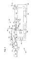
- FIG 1 is a simplified schematic of a standard gas turbine 105 operating in a closed-cycle mode, illustrating a first embodiment of the present invention.
- a site 100 includes: a gas turbine 105, operatively connected to a heat recovery steam generator (HRSG) 110, a load 115, and an extraction 210.
- the gas turbine 105 may include a GT compressor 120 having a compressor inlet 121 and a compressor outlet 123.
- the GT compressor 120 ingests the working fluid received from the EGR system 240, compresses the working fluid, and discharges the compressed working fluid through the compressor outlet 123.
- the gas turbine 105 may include an oxidant compressor 155 that ingests an oxidant, hereafter referred to as ambient air, through an ac_inlet 157, compresses the same, and discharges the compressed air through the ac_outlet 159.
- the oxidant compressor 155 may deliver the compressed airstream to the primary combustion system 130 through an airstream conduit 165; which may include: a vent conduit 175, a vent valve 180, booster compressor 160 and isolation valve 170; each of these components may be operated as needed.
- the GT compressor 120 operates independently and distinct of the oxidant compressor 155.
- the gas turbine 105 also includes a primary combustion system 130 that receives through a head end: the compressed working fluid from the GT compressor outlet 123; a fuel supply 185, comprising a first fuel conduit 190 and first fuel valve 195; and the compressed ambient air from the airstream conduit 165.
- the primary combustion system 130 combusts those fluids creating the working fluid that may be substantially oxygen-free.
- the working fluid then exits the primary combustion system 130 through a discharge end.
- the fuel supply 185 may provide fuel that derives from a single source to the primary combustion systems 130.
- the fuel supply 185 may provide fuel that derives from a first fuel source to the primary combustion system 130; and fuel that derives from a second fuel source to the combustion system 130.
- An embodiment of the gas turbine 105 also includes a primary turbine section 135 having a PT_inlet 137 that receives some of the working fluid from the primary combustion system 130 of which the PT_inlet 137 is fluidly connected.
- the primary turbine section 135 may include rotating components and stationary components installed alternatively in the axial direction adjacent a rotor 125.
- the primary turbine section 135 converts the working fluid to a mechanical torque which drives the load 115 (generator, pump, compressor, etc).
- the primary turbine section 135 may then discharge the working fluid through the PT_outlet 139 to an exhaust section 150 and then to the HRSG 110, which operatively transfers heat from the working fluid to water for steam generation.
- the EGR system 240 operatively returns to the GT compressor 120 the working fluid exiting the HRSG 110.
- the EGR system 240 receives the working fluid discharged by the HRSG 110; which is fluidly connected to a receiving or upstream end of the EGR system 240.
- a discharge end of the EGR system 240 may be fluidly connected to the inlet of the GT compressor 120, as described.
- the GT compressor 120 ingests the working fluid.
- An embodiment of the EGR system 240 comprises a control device that operatively adjusts a physical property of the working fluid.
- the control device may comprise the form of: a heat exchanger 245, an EGR compressor 250, and/or an intercooler 265.
- embodiments of the EGR system may comprise multiple control devices.
- the EGR system 240 may also comprise an EGR damper 235 which facilitates a purging process, which may vent purged fluid to atmosphere via a discharge 270.
- the extraction 210 operationally removes a portion of the working fluid for use by a third-party process.
- the extraction 210 may be integrated with a circuit that comprises an extraction isolation valve 215, a recirculation conduit 220 and a recirculation valve 225.
- the extracted working fluid may be a substantially oxygen-free desirable gas; useful for many third-party processes. As discussed, this desirable gas may include, but is not limiting to CO2, N2, or Argon. In a non-limiting example, up to 100% of the working fluid may flow through the extraction 210 to the third-party process.
- combustion system 130 that is immediately adjacent to the extraction 210 may operate in a substantially stoichiometric operating mode.
- various embodiments of the present invention may operate a control device and a compressor in a manner that determines a parameter of the working fluid flowing through an extraction.
- the parameter comprises at least one of: a pressure, a temperature, humidity, or other physical property. Therefore, it is not the intent to limit the parameter to a pressure and/or temperature.
- embodiments of the present invention may position the extraction 210 at, or in the GT compressor 120, the primary combustion system 130, or the primary turbine section 135.
- the working fluid may exhibit a relatively higher pressure, useful for high pressure applications.
- These applications may include, but are not limited to: a carbon capture system (CCS), or other applications that desire high pressure, substantially oxygen-free, gas.
- CCS carbon capture system
- FIG 1 describes the basic concept of certain aspects of the invention.
- components and elements that correspond to those identified in FIG 1 are identified with similar reference numerals in FIGS 2-4 , but are only discussed in particular as necessary or desirable to an understanding of each embodiment.
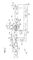
- FIG 2 is a simplified schematic of a reheat gas turbine operating in a closed-cycle mode, illustrating a second embodiment of the present invention.
- the primary difference between this second embodiment and the first embodiment is the application of the present invention to a reheat gas turbine 107.
- the reheat gas turbine 107 comprises the following additional components (as illustrated in FIG 2 ): a secondary combustion system 140, a secondary turbine section 145, and a second fuel conduit and valve 200, 205 respectively.
- the first fuel conduit 190 and the second fuel conduit 200 may supply different fuels to the respective combustion systems 130,140.
- the secondary combustion system 140 may function as a stoichiometric system.
- the first and second embodiments of the present invention may operate as follows.
- the oxidant compressor 155 delivers compressed ambient air to the primary combustion system 130
- the compressor 120 delivers compressed working fluid to the primary combustion system 130.
- the booster compressor 160 may be used.
- the fuel supply nearly simultaneously delivers a hydrocarbon-based fuel (natural gas, or the like) to the primary combustion system 130.
- some of the working fluid may flow through extraction 210. In a non-limiting example, up to 100% of the working fluid may flow through the extraction 210 to the third-party process.
- the primary combustion system 130 combusts the mixture of those three fluids to create the working fluid, which engages the primary turbine section 135.
- the working fluid may flow through the secondary combustion system 140.
- the working fluid may be mixed with a fuel from the second fuel circuit 200; and a second combustion process occurs.
- the fuel supplied by the first fuel conduit 190 may differ from the fuel supplied by the second fuel conduit 200.
- the working fluid may engage the secondary turbine section 145 and then the exhaust section 150.
- the working fluid may enter the HRSG 110, as described.
- the working fluid may enter the EGR system 240.
- the working fluid may flow through the heat exchanger 245, where a temperature reduction may occur.
- FIG 2 represents a reheat gas turbine application.
- the second embodiment of the present invention may operate substantially similar to the first embodiment, although the reheat operation differs from non-reheat operation.
- combustion system 130,140 that is immediately adjacent to the extraction 210 may operate in a substantially stoichiometric operating mode.
- FIG 3 is a simplified schematic of a standard gas turbine operating in a closed-cycle mode, illustrating a third embodiment of the present invention.
- the primary difference between this third embodiment and the first embodiment is the location of the extraction 255, which may be positioned at an optimum location on the EGR system.
- the extraction 255 may have a pressure in the low to medium range, relative to the high pressure extraction 210 associated with embodiments associated with FIGS 1 and 2 . This may be desirable for third-party applications that desire a substantially oxygen-free gas and in a relatively low to medium pressure range.
- combustion system 130,140 that is immediately adjacent to the extraction 210 may operate in a substantially stoichiometric operating mode.
- FIG 4 is a simplified schematic of a reheat gas turbine operating in a closed-cycle mode, illustrating a fourth embodiment of the present invention.
- the primary difference between this fourth embodiment and the third embodiment is the application of third embodiment to a reheat gas turbine 107.
- the reheat gas turbine 107 comprises the following additional components (as illustrated in FIG 4 ): a secondary combustion system 140, a secondary turbine section 145, and a second fuel conduit and valve 200, 205 respectively.
- the first fuel conduit 190 and the second fuel conduit 200 may supply different fuels to the respective combustion systems 130,140.
- combustion system 130,140 that is immediately adjacent to the extraction 255 may operate in a substantially stoichiometric operating mode.
- the secondary combustion system 140 may function as a stoichiometric system.
- the third and fourth embodiments of the present invention may operate as follows.
- the oxidant compressor 155 delivers compressed ambient air to the primary combustion system 130
- the GT compressor 120 delivers compressed working fluid to the primary combustion system 130. If ambient air at a higher pressure, and/or flow rate, is required, then the booster compressor 160 may be used.
- the fuel supply nearly simultaneously delivers a hydrocarbon-based fuel (natural gas, or the like) to the primary combustion system 130.
- the primary combustion system 130 combusts the mixture of those three fluids to create the working fluid, which then engages the primary turbine section 135.
- the working fluid may flow through the exhaust section 150.
- the working fluid may flow from the primary turbine section 135 to the secondary combustion system 140.
- the working fluid may be mixed with a fuel from the second fuel circuit 200; and a second combustion process occurs.
- the fuel supplied by the first fuel conduit 190 may differ from the fuel supplied by the second fuel conduit 200.
- the working fluid may engage the secondary turbine section 145 and then the exhaust section 150.
- the working fluid may enter the HRSG 110, after exiting the exhaust section 150, as described.
- the working fluid may enter the EGR system 240.
- the working fluid may flow through the heat exchanger 245, where a temperature reduction may occur.
- the working fluid may flow through an EGR compressor 250 (if supplied).
- some of the working fluid may flow through extraction 255.
- up to 100% of the working fluid may flow through the extraction 255 to the third-party process.
- the extraction 255 may be located between the EGR compressor 250 and the intercooler 265; on EGR systems 240 so configured.
- Elements 250, 265 serve to adjust the pressure and/or temperature of the working fluid prior to returning to the gas turbine 105 through the compressor 120.
- FIG 4 represents a reheat gas turbine application.
- the fourth embodiment of the present invention may operate substantially similar to the third embodiment, although the reheat operation differs.
- the third and fourth embodiments of the present invention may provide substantial flexibility for a user having an EGR configuration that includes both the EGR compressor 250 and the intercooler 265.
- the EGR compressor 250 and the GT compressor 120 may operate in a manner where the pressure ratio across each compressor 120, 250 is actively changed to create a desired pressure at the extraction 255. This may allow a user to change the working fluid pressure as the needs of the third-party process changes.
- Another benefit with this EGR configuration involves the temperature of the working fluid.
- the intercooler 265 may be used to adjust the temperature of the working fluid entering the GT compressor 120. The use of the intercooler 265 may lower the temperature at the aft-end of the GT compressor 120 and/or at the entrance of the combustion system. This may provide a cost savings on the associated materials.
- the intercooler 265 may affect the temperature of the cooling fluid supplied to the turbine section(s); possibly allowing the removal of an often used cooling fluid skid.
- connection locations may include, but are not limited to, the combustion system 130,140; the primary turbine section 135; or the secondary turbine section 145.
- Embodiments of the present invention may be applied to a gas turbine in either a simple-cycle configuration or a combined-cycle configuration.
- the discussion herein is based on a gas turbine in a combined-cycle configuration. It is not the intent to limit the present invention to combined-cycle applications.
- Embodiments of the present invention may be applied to a gas turbine operating in a simple-cycle configuration.
- the working fluid may flow from the last turbine section 135,145 through the exhaust section 150 and then to the EGR system 240. This operation may supply a substantially oxygen-free fluid to the inlet 121 of the GT compressor 120, promoting stoichiometric operation.
Landscapes
- Engineering & Computer Science (AREA)
- Chemical & Material Sciences (AREA)
- Combustion & Propulsion (AREA)
- Mechanical Engineering (AREA)
- General Engineering & Computer Science (AREA)
- Physics & Mathematics (AREA)
- Fluid Mechanics (AREA)
- Life Sciences & Earth Sciences (AREA)
- Sustainable Development (AREA)
- Engine Equipment That Uses Special Cycles (AREA)
- Exhaust-Gas Circulating Devices (AREA)
Abstract
Description
- The present application relates generally to a combined-cycle powerplant; and more particularly to a system and method for operating a turbomachine incorporated with stoichiometric exhaust gas recirculation (S-EGR).
- In an air-ingesting turbomachine, compressed air and fuel are mixed and combusted to produce a high energy fluid (hereinafter "working fluid") that is directed to a turbine section. The working fluid interacts with turbine buckets to generate mechanical energy, which is transferred to a load. In particular, the turbine buckets rotate a shaft coupled to the load, such as an electrical generator. The shaft rotation induces current in a coil electrically coupled to an external electrical circuit. In the case where the turbomachine is part of a combined cycle power plant, the high energy fluids exiting the turbine section are directed to a heat recovery steam generator (HRSG), where heat from the working fluid is transferred to water for steam generation.
- The combustion process creates undesirable emissions and/or pollutants, such as Carbon Monoxide (CO) and Oxides of Nitrogen (NOx). Reducing these pollutants is necessary for environmental and/or regulatory reasons. Exhaust gas recirculation (EGR) processes help to reduce these pollutants.
- S-EGR is a form of EGR where the combustion process consumes a supplied oxidant. The oxidant can include, for example, air or an oxygen source. In a S-EGR system, only enough oxidant is supplied to the combustion system to achieve complete combustion, on a mole basis. The S-EGR process can be configured to yield an exhaust stream that includes a relatively high concentration of a desirable gas and is substantially oxygen-free. This desirable gas includes, but is not limited to: Carbon Dioxide (CO2), Nitrogen (N2), or Argon. Significantly, there is a desire for S-EGR systems and methods that can generate exhaust streams with relatively high concentration of the desirable gas, which can then be supplied and used in third party processes.
- Certain embodiments commensurate in scope with the originally claimed invention are summarized below. These embodiments are not intended to limit the scope of the claimed invention, but rather these embodiments are intended only to provide a brief summary of possible forms of the invention. Indeed, the invention may encompass a variety of forms that may be similar to or different from the embodiments set forth below.
- In accordance with a first embodiment of the present invention, a system comprises: an oxidant compressor comprising an ac_inlet and an ac_outlet; a compressor comprising a compressor inlet and a compressor outlet; wherein the compressor operates independently of the oxidant compressor; at least one combustion system that operatively generates a working fluid and comprises a head end and a discharge end, wherein the head end is fluidly connected to: an air stream conduit, the compressor outlet, and wherein the at least one combustion system is connected to a first fuel supply; a primary turbine section operatively connected to the compressor, wherein the turbine section comprises a PT_inlet which receives the working fluid from the at least one combustion system, and a PT_outlet that discharges the working fluid; an exhaust gas recirculation (EGR) system fluidly connected between the discharge of an exhaust section and the compressor inlet, wherein the compressor inlet ingests the working fluid exiting the exhaust section; wherein the EGR system comprises a control device for adjusting a physical property of the working fluid; and an extraction that removes a portion of the working fluid; wherein the control device and the compressor jointly operate in a manner that determines a pressure of the working fluid flowing through the extraction.
- In accordance with a second embodiment of the present invention, a method comprises: operating an oxidant compressor to compress an ingested oxidant; operating a compressor to compress a working fluid, wherein the operation of the oxidant compressor is independent of the operation of the compressor; passing to a primary combustion system: a compressed oxidant, derived from the oxidant compressor, and a compressed working fluid, derived from the compressor; delivering a fuel to the primary combustion system which operatively combusts a mixture of: the fuel, the compressed oxidant and the compressed working fluid; creating the working fluid; passing the working fluid from the primary combustion system to a primary turbine section; operating an EGR system to recirculate the working fluid exiting an exhaust section to flow into an inlet of the compressor; wherein the EGR system comprises a control device for adjusting a physical property of the working fluid; extracting a portion of the working fluid; wherein the working fluid is nearly oxygen-free, and the primary combustion system operates in a substantially stoichiometric manner; and operating the control device and the compressor in a manner that determines a pressure of the working fluid flowing through the extraction; wherein the method yields a substantially oxygen-free flow of a desirable gas.
- Various features, aspects, and advantages of the present invention may become better understood when the following detailed description is read with reference to the accompanying figures (FIGS) in which like characters represent like elements/parts throughout the FIGS., and in which:
-
FIG 1 is a simplified schematic of a standard gas turbine operating in a closed-cycle mode, illustrating a first embodiment of the present invention. -
FIG 2 is a simplified schematic of a reheat gas turbine operating in a closed-cycle mode, illustrating a second embodiment of the present invention. -
FIG 3 is a simplified schematic of a standard gas turbine operating in a closed-cycle mode, illustrating a third embodiment of the present invention. -
FIG 4 is a simplified schematic of a reheat gas turbine operating in a closed-cycle mode, illustrating a fourth embodiment of the present invention. - One or more specific embodiments of the present invention will be described below. In an effort to provide a concise description of these embodiments, all features of an actual implementation may not be described in the specification. It should be appreciated that in the development of any such actual implementation, as in an engineering or design project, numerous implementation-specific decisions are made to achieve the specific goals, such as compliance with system-related and/or business-related constraints, which may vary from one implementation to another. Moreover, it should be appreciated that such effort might be complex and time consuming, but would nevertheless be a routine undertaking of design, fabrication, and manufacture for those of ordinary skill having the benefit of this disclosure.
- Detailed example embodiments are disclosed herein. However, specific structural and functional details disclosed herein are merely representative for purposes of describing example embodiments. Embodiments of the present invention may, however, be embodied in many alternate forms, and should not be construed as limited to only the embodiments set forth herein.
- Accordingly, while example embodiments are capable of various modifications and alternative forms, embodiments thereof are illustrated by way of example in the figures and will herein be described in detail. It should be understood, however, that there is no intent to limit example embodiments to the particular forms disclosed, but to the contrary, example embodiments are to cover all modifications, equivalents, and alternatives falling within the scope of the present invention.
- The terminology used herein is for describing particular embodiments only and is not intended to be limiting of example embodiments. As used herein, the singular forms "a", "an" and "the" are intended to include the plural forms as well, unless the context clearly indicates otherwise. The terms "comprises", "comprising", "includes" and/or "including", when used herein, specify the presence of stated features, integers, steps, operations, elements, and/or components, but do not preclude the presence or addition of one or more other features, integers, steps, operations, elements, components, and/or groups thereof.
- Although the terms first, second, primary, secondary, etc. may be used herein to describe various elements, these elements should not be limited by these terms. These terms are only used to distinguish one element from another. For example, but not limiting to, a first element could be termed a second element, and, similarly, a second element could be termed a first element, without departing from the scope of example embodiments. As used herein, the term "and/or" includes any, and all, combinations of one or more of the associated listed items.
- Certain terminology may be used herein for the convenience of the reader only and is not to be taken as a limitation on the scope of the invention. For example, words such as "upper", "lower", "left", "right", "front", "rear", "top", "bottom", "horizontal", "vertical", "upstream", "downstream", "fore", "aft", and the like; merely describe the configuration shown in the FIGS. Indeed, the element or elements of an embodiment of the present invention may be oriented in any direction and the terminology, therefore, should be understood as encompassing such variations unless specified otherwise.
- Various embodiments of the present invention provide a system and method that creates a flow stream of CO2 that is substantially free of oxygen. Here, the CO2 may be separated from N2 in a cost-effective manner.
- The present invention may be applied to a variety of air-ingesting turbomachines. This may include, but is not limited to, heavy-duty gas turbines, aero-derivatives, or the like. Although the following discussion relates to the gas turbines illustrated in
FIGS 1-4 , embodiments of the present invention may be applied to a gas turbine with a different configuration. For example, but not limiting of, the present invention may apply to a gas turbine with different, or additional, components than those illustrated inFIGS 1-4 . - Embodiments of the present invention may apply to, but are not limited to, a combined-cycle powerplant operating under stoichiometric, or non-stoichiometric, conditions.
- Stoichiometric conditions may be considered operating a combustion process with only enough oxidizer, for example oxygen, to promote complete, or substantially complete, combustion. Complete combustion bums a hydrocarbon-based fuel with oxygen and yields carbon dioxide and water as the primary byproducts. Many factors may influence whether complete combustion occurs. These factors may include, but are not limited to, oxygen in proximity to a fuel molecule, vibrations, dynamic events, shock waves, etc. In order to promote carbon dioxide formation rather than carbon monoxide formation, additional oxygen is normally delivered with the fuel supply to promote a complete combustion reaction.
- Non-stoichiometric conditions may be considered operating a combustion system with either more or less oxidizer than is required for the combustion process. Non-stoichiometric conditions are common on a standard combustion system, or non S-EGR systems.
- As used herein, "working fluid" may be considered the resultant of the combustion process. Embodiments of the present invention are not limited to a working fluid having a specific composition or physical properties. On the contrary, the composition and/or a physical property of the working fluid may change while flowing through the various components, systems, and/or structures described herein.
- Referring now to the FIGS, where the various numbers represent like components throughout the several views,
FIG 1 is a simplified schematic of astandard gas turbine 105 operating in a closed-cycle mode, illustrating a first embodiment of the present invention. - In
FIG 1 , asite 100 includes: agas turbine 105, operatively connected to a heat recovery steam generator (HRSG) 110, aload 115, and anextraction 210. Thegas turbine 105 may include aGT compressor 120 having acompressor inlet 121 and acompressor outlet 123. TheGT compressor 120 ingests the working fluid received from theEGR system 240, compresses the working fluid, and discharges the compressed working fluid through thecompressor outlet 123. Thegas turbine 105 may include anoxidant compressor 155 that ingests an oxidant, hereafter referred to as ambient air, through anac_inlet 157, compresses the same, and discharges the compressed air through theac_outlet 159. Theoxidant compressor 155 may deliver the compressed airstream to theprimary combustion system 130 through anairstream conduit 165; which may include: avent conduit 175, avent valve 180,booster compressor 160 andisolation valve 170; each of these components may be operated as needed. - In embodiments of the present invention, the
GT compressor 120 operates independently and distinct of theoxidant compressor 155. Thegas turbine 105 also includes aprimary combustion system 130 that receives through a head end: the compressed working fluid from theGT compressor outlet 123; afuel supply 185, comprising afirst fuel conduit 190 andfirst fuel valve 195; and the compressed ambient air from theairstream conduit 165. Theprimary combustion system 130 combusts those fluids creating the working fluid that may be substantially oxygen-free. The working fluid then exits theprimary combustion system 130 through a discharge end. - The
fuel supply 185, in accordance with embodiments of the present invention, may provide fuel that derives from a single source to theprimary combustion systems 130. Alternatively, thefuel supply 185 may provide fuel that derives from a first fuel source to theprimary combustion system 130; and fuel that derives from a second fuel source to thecombustion system 130. - An embodiment of the
gas turbine 105, also includes aprimary turbine section 135 having aPT_inlet 137 that receives some of the working fluid from theprimary combustion system 130 of which thePT_inlet 137 is fluidly connected. Theprimary turbine section 135 may include rotating components and stationary components installed alternatively in the axial direction adjacent arotor 125. Theprimary turbine section 135 converts the working fluid to a mechanical torque which drives the load 115 (generator, pump, compressor, etc). Theprimary turbine section 135 may then discharge the working fluid through thePT_outlet 139 to anexhaust section 150 and then to theHRSG 110, which operatively transfers heat from the working fluid to water for steam generation. - The
EGR system 240 operatively returns to theGT compressor 120 the working fluid exiting theHRSG 110. TheEGR system 240 receives the working fluid discharged by theHRSG 110; which is fluidly connected to a receiving or upstream end of theEGR system 240. A discharge end of theEGR system 240 may be fluidly connected to the inlet of theGT compressor 120, as described. Here, theGT compressor 120 ingests the working fluid. - An embodiment of the
EGR system 240 comprises a control device that operatively adjusts a physical property of the working fluid. For example, but not limited to, the control device may comprise the form of: aheat exchanger 245, anEGR compressor 250, and/or anintercooler 265. As discussed below, embodiments of the EGR system may comprise multiple control devices. TheEGR system 240 may also comprise anEGR damper 235 which facilitates a purging process, which may vent purged fluid to atmosphere via adischarge 270. - The
extraction 210 operationally removes a portion of the working fluid for use by a third-party process. Theextraction 210 may be integrated with a circuit that comprises anextraction isolation valve 215, arecirculation conduit 220 and arecirculation valve 225. The extracted working fluid may be a substantially oxygen-free desirable gas; useful for many third-party processes. As discussed, this desirable gas may include, but is not limiting to CO2, N2, or Argon. In a non-limiting example, up to 100% of the working fluid may flow through theextraction 210 to the third-party process. - As described herein, the
combustion system 130 that is immediately adjacent to theextraction 210 may operate in a substantially stoichiometric operating mode. - As described herein, various embodiments of the present invention may operate a control device and a compressor in a manner that determines a parameter of the working fluid flowing through an extraction. The parameter comprises at least one of: a pressure, a temperature, humidity, or other physical property. Therefore, it is not the intent to limit the parameter to a pressure and/or temperature.
- As illustrated in
FIGS 1 and3 , embodiments of the present invention may position theextraction 210 at, or in theGT compressor 120, theprimary combustion system 130, or theprimary turbine section 135. Here, the working fluid may exhibit a relatively higher pressure, useful for high pressure applications. These applications may include, but are not limited to: a carbon capture system (CCS), or other applications that desire high pressure, substantially oxygen-free, gas. - The above discussion, in relation to
FIG 1 , describes the basic concept of certain aspects of the invention. For convenience, components and elements that correspond to those identified inFIG 1 are identified with similar reference numerals inFIGS 2-4 , but are only discussed in particular as necessary or desirable to an understanding of each embodiment. -
FIG 2 is a simplified schematic of a reheat gas turbine operating in a closed-cycle mode, illustrating a second embodiment of the present invention. The primary difference between this second embodiment and the first embodiment is the application of the present invention to areheat gas turbine 107. Here, thereheat gas turbine 107 comprises the following additional components (as illustrated inFIG 2 ): asecondary combustion system 140, asecondary turbine section 145, and a second fuel conduit andvalve first fuel conduit 190 and thesecond fuel conduit 200 may supply different fuels to the respective combustion systems 130,140. - Operationally, in this second embodiment, the
secondary combustion system 140 may function as a stoichiometric system. In use, the first and second embodiments of the present invention may operate as follows. As theoxidant compressor 155 delivers compressed ambient air to theprimary combustion system 130, thecompressor 120 delivers compressed working fluid to theprimary combustion system 130. If ambient air at a higher pressure and/or flow rate, is required, then thebooster compressor 160 may be used. The fuel supply nearly simultaneously delivers a hydrocarbon-based fuel (natural gas, or the like) to theprimary combustion system 130. Next, some of the working fluid may flow throughextraction 210. In a non-limiting example, up to 100% of the working fluid may flow through theextraction 210 to the third-party process. - Next, the
primary combustion system 130 combusts the mixture of those three fluids to create the working fluid, which engages theprimary turbine section 135. Next, the working fluid may flow through thesecondary combustion system 140. Here, the working fluid may be mixed with a fuel from thesecond fuel circuit 200; and a second combustion process occurs. In embodiments of the present invention, the fuel supplied by thefirst fuel conduit 190 may differ from the fuel supplied by thesecond fuel conduit 200. Next, the working fluid may engage thesecondary turbine section 145 and then theexhaust section 150. Next, the working fluid may enter theHRSG 110, as described. Next, the working fluid may enter theEGR system 240. Depending on the configuration of theEGR system 240, the working fluid may flow through theheat exchanger 245, where a temperature reduction may occur. Then, the working fluid may flow through anEGR compressor 250 and/or anintercooler 265.Elements reheat gas turbine 107 through thecompressor 120. As discussed,FIG 2 represents a reheat gas turbine application. The second embodiment of the present invention may operate substantially similar to the first embodiment, although the reheat operation differs from non-reheat operation. - As described herein, the combustion system 130,140 that is immediately adjacent to the
extraction 210 may operate in a substantially stoichiometric operating mode. -
FIG 3 is a simplified schematic of a standard gas turbine operating in a closed-cycle mode, illustrating a third embodiment of the present invention. The primary difference between this third embodiment and the first embodiment is the location of theextraction 255, which may be positioned at an optimum location on the EGR system. Theextraction 255 may have a pressure in the low to medium range, relative to thehigh pressure extraction 210 associated with embodiments associated withFIGS 1 and2 . This may be desirable for third-party applications that desire a substantially oxygen-free gas and in a relatively low to medium pressure range. - As described herein, the combustion system 130,140 that is immediately adjacent to the
extraction 210 may operate in a substantially stoichiometric operating mode. -
FIG 4 is a simplified schematic of a reheat gas turbine operating in a closed-cycle mode, illustrating a fourth embodiment of the present invention. The primary difference between this fourth embodiment and the third embodiment is the application of third embodiment to areheat gas turbine 107. Here, thereheat gas turbine 107 comprises the following additional components (as illustrated inFIG 4 ): asecondary combustion system 140, asecondary turbine section 145, and a second fuel conduit andvalve first fuel conduit 190 and thesecond fuel conduit 200 may supply different fuels to the respective combustion systems 130,140. - As described herein, the combustion system 130,140 that is immediately adjacent to the
extraction 255 may operate in a substantially stoichiometric operating mode. - Operationally, in this fourth embodiment, the
secondary combustion system 140 may function as a stoichiometric system. In use, the third and fourth embodiments of the present invention may operate as follows. As theoxidant compressor 155 delivers compressed ambient air to theprimary combustion system 130, theGT compressor 120 delivers compressed working fluid to theprimary combustion system 130. If ambient air at a higher pressure, and/or flow rate, is required, then thebooster compressor 160 may be used. The fuel supply nearly simultaneously delivers a hydrocarbon-based fuel (natural gas, or the like) to theprimary combustion system 130. - Next, the
primary combustion system 130 combusts the mixture of those three fluids to create the working fluid, which then engages theprimary turbine section 135. Next, the working fluid may flow through theexhaust section 150. - For the reheat embodiment of
FIG 4 , the working fluid may flow from theprimary turbine section 135 to thesecondary combustion system 140. Here, the working fluid may be mixed with a fuel from thesecond fuel circuit 200; and a second combustion process occurs. In embodiments of the present invention, the fuel supplied by thefirst fuel conduit 190 may differ from the fuel supplied by thesecond fuel conduit 200. Next, the working fluid may engage thesecondary turbine section 145 and then theexhaust section 150. - For both the reheat and non-reheat embodiments, the working fluid may enter the
HRSG 110, after exiting theexhaust section 150, as described. Next the working fluid may enter theEGR system 240. Depending on the configuration of theEGR system 240, the working fluid may flow through theheat exchanger 245, where a temperature reduction may occur. Then, the working fluid may flow through an EGR compressor 250 (if supplied). Next, some of the working fluid may flow throughextraction 255. In a non-limiting example, up to 100% of the working fluid may flow through theextraction 255 to the third-party process. In an embodiment of the present invention, theextraction 255 may be located between theEGR compressor 250 and theintercooler 265; onEGR systems 240 so configured.Elements gas turbine 105 through thecompressor 120. As discussed,FIG 4 represents a reheat gas turbine application. The fourth embodiment of the present invention may operate substantially similar to the third embodiment, although the reheat operation differs. - The third and fourth embodiments of the present invention may provide substantial flexibility for a user having an EGR configuration that includes both the
EGR compressor 250 and theintercooler 265. First, theEGR compressor 250 and theGT compressor 120 may operate in a manner where the pressure ratio across eachcompressor extraction 255. This may allow a user to change the working fluid pressure as the needs of the third-party process changes. Another benefit with this EGR configuration involves the temperature of the working fluid. Theintercooler 265 may be used to adjust the temperature of the working fluid entering theGT compressor 120. The use of theintercooler 265 may lower the temperature at the aft-end of theGT compressor 120 and/or at the entrance of the combustion system. This may provide a cost savings on the associated materials. Furthermore, theintercooler 265 may affect the temperature of the cooling fluid supplied to the turbine section(s); possibly allowing the removal of an often used cooling fluid skid. - Various embodiments of the present invention also provide flexibility on where to connect the
extraction 210 to thegas turbine 105. Some connection locations may include, but are not limited to, the combustion system 130,140; theprimary turbine section 135; or thesecondary turbine section 145. - Embodiments of the present invention may be applied to a gas turbine in either a simple-cycle configuration or a combined-cycle configuration. Although, the discussion herein is based on a gas turbine in a combined-cycle configuration. It is not the intent to limit the present invention to combined-cycle applications. Embodiments of the present invention may be applied to a gas turbine operating in a simple-cycle configuration. Here, the working fluid may flow from the last turbine section 135,145 through the
exhaust section 150 and then to theEGR system 240. This operation may supply a substantially oxygen-free fluid to theinlet 121 of theGT compressor 120, promoting stoichiometric operation. - Although specific embodiments have been illustrated and described herein, those of ordinary skill in the art appreciate that any arrangement, which is calculated to achieve the same purpose, may be substituted for the specific embodiments shown and that the invention has other applications in other environments. This application is intended to cover any adaptations or variations of the present invention. The following claims are in no way intended to limit the scope of the invention to the specific embodiments described herein.
- As one of ordinary skill in the art will appreciate, the many varying features and configurations described above in relation to the several embodiments may be further selectively applied to form other possible embodiments of the present invention. Those skilled in the art will further understand that all possible iterations of the present invention are not provided or discussed in detail, even though all combinations and possible embodiments embraced by the several claims below or otherwise are intended to be part of the instant application. In addition, from the above description of several embodiments of the invention, those skilled in the art will perceive improvements, changes, and modifications. Such improvements, changes, and modifications within the skill of the art are also intended to be covered by the appended claims. Further, it should be apparent that the foregoing relates only to the described embodiments of the present application and that numerous changes and modifications may be made herein without departing from the spirit and scope of the application as defined by the following claims and the equivalents thereof.
- Various aspects and embodiments of the present invention are defined by the following numbered clauses:
- 1. A system comprising:
- an oxidant compressor comprising an ac_inlet and an ac_outlet;
- a compressor comprising a compressor inlet and a compressor outlet; wherein the compressor operates independently of the oxidant compressor;
- at least one combustion system that operatively generates a working fluid and comprises a head end and a discharge end, wherein the head end is fluidly connected to: an air stream conduit, the compressor outlet, and wherein the at least one combustion system is connected to a first fuel supply;
- a primary turbine section operatively connected to the compressor, wherein the turbine section comprises a PT_inlet which receives the working fluid from the at least one combustion system, and a PT_outlet that discharges the working fluid;
- an exhaust gas recirculation (EGR) system fluidly connected between the discharge of an exhaust section and the compressor inlet, wherein the compressor inlet ingests the working fluid exiting the exhaust section; wherein the EGR system comprises a control device for adjusting a physical property of the working fluid; and
- an extraction that removes a portion of the working fluid; wherein the control device and the compressor jointly operate in a manner that determines a pressure of the working fluid flowing through the extraction.
- 2. The system of clause 1, wherein a combustion system immediately adjacent the extraction is operated in a substantially stoichiometric operating condition.
- 3. The system of any preceding clause, wherein the control device comprises at least one of: an intercooler, a compressor, or a heat exchanger.
- 4. The system of any preceding clause, wherein the extraction is fluidly connected to at least one of the following areas: within the compressor, the at least one combustion system, the primary turbine section, or the secondary turbine section.
- 5. The system of any preceding clause, further comprising a secondary combustion system fluidly connected downstream of the primary turbine section, wherein the secondary combustion system receives fuel from the first fuel supply, a second fuel supply, or combinations thereof.
- 6. The system of any preceding clause, further comprising a secondary turbine section connected downstream of the secondary combustion system and upstream of the exhaust section.
- 7. The system of any preceding clause, wherein the extraction is fluidly connected to the EGR system in a location downstream of the control device.
- 8. The system of any preceding clause, wherein the extraction is fluidly connected to the EGR system in a location at, or upstream of, the control device.
- 9. The system of any preceding clause, wherein the EGR system comprises an EGR compressor and an intercooler located between the EGR compressor and the compressor inlet.
- 10. The system of any preceding clause, wherein the control device and the compressor jointly operate in a manner that determines a temperature of the working fluid flowing through the extraction.
- 11. The system of any preceding clause, further comprising a heat recovery steam generator (HRSG) fluidly connected to the PT_outlet, wherein the HRSG operatively removes heat from the working fluid and then discharges the working fluid to the EGR system.
- 12. The system of any preceding clause, further comprising a heat recovery steam generator (HRSG) fluidly connected to the PT_outlet, wherein the HRSG operatively removes heat from the working fluid and then discharges the working fluid to the EGR system.
- 13. A system comprising:
- an oxidant compressor comprising an ac inlet and an ac outlet;
- a compressor comprising a compressor inlet and a compressor outlet; wherein the compressor operates independently of the oxidant compressor;
- at least one combustion system that operatively generates a working fluid and comprises a head end and a discharge end, wherein the head end is fluidly connected to: an air stream conduit, the compressor outlet, and wherein the at least one combustion system is connected to a first fuel supply;
- a primary turbine section operatively connected to the compressor, wherein the turbine section comprises a PT_inlet which receives the working fluid from the at least one combustion system, and a PT_outlet that discharges the working fluid;
- an exhaust gas recirculation (EGR) system fluidly connected between the discharge of an exhaust section and the compressor inlet, wherein the compressor inlet ingests the working fluid exiting the exhaust section; wherein the EGR system comprises a control device for adjusting a physical property of the working fluid; and
- a extraction system that removes a portion of the working fluid; wherein the control device and the compressor jointly operate in a manner that determines a temperature of the working fluid flowing through the extraction.
- 14. The system of any preceding clause, wherein a combustion system immediately adjacent the extraction is operated in a substantially stoichiometric operating condition.
- 15. The system of any preceding clause, wherein the control device comprises at least one of: an intercooler, a compressor, or a heat exchanger.
- 16. The system of any preceding clause, wherein the extraction is fluidly connected to at least one of the following areas: within the compressor, the at least one combustion system, the primary turbine section, or the secondary turbine section.
- 17. The system of any preceding clause, further comprising a secondary combustion system fluidly connected downstream of the primary turbine section, wherein the secondary combustion system receives fuel from the first fuel supply, a second fuel supply, or combinations thereof.
- 18. The system of any preceding clause, further comprising a secondary turbine section connected downstream of the secondary combustion system and upstream of the exhaust section.
- 19. The system of any preceding clause, wherein the extraction is fluidly connected to the EGR system in a location downstream of the control device.
- 20. The system of any preceding clause, wherein the extraction is fluidly connected to the EGR system in a location at, or upstream of, the control device.
- 21. The system of any preceding clause, wherein the EGR system comprises an EGR compressor and an intercooler located between the EGR compressor and the compressor inlet.
- 22. The system of any preceding clause, wherein the control device and the compressor jointly operate in a manner that determines a pressure of the working fluid flowing through the extraction.
- 23. The system of any preceding clause, a heat recovery steam generator (HRSG) fluidly connected to the PT_outlet, wherein the HRSG operatively removes heat from the working fluid and then discharges the working fluid to the EGR system.
- 24. A system comprising:
- an oxidant compressor comprising an ac_inlet and an ac_outlet;
- a compressor comprising a compressor inlet and a compressor outlet; wherein the compressor operates independently of the oxidant compressor;
- at least one combustion system that operatively generates a working fluid and comprises a head end and a discharge end, wherein the head end is fluidly connected to: an air stream conduit, the compressor outlet, and wherein the at least one combustion system is connected to a first fuel supply;
- a primary turbine section operatively connected to the compressor, wherein the turbine section comprises a PT_inlet which receives the working fluid from the at least one combustion system, and a PT_outlet that discharges the working fluid;
- an exhaust gas recirculation (EGR) system fluidly connected between the discharge of an exhaust section and the compressor inlet, wherein the compressor inlet ingests the working fluid exiting the exhaust section; wherein the EGR system comprises a control device for adjusting a physical property of the working fluid; and
- a extraction system that removes a portion of the working fluid; wherein the control device and the compressor jointly operate in a manner that determines a temperature and a pressure of the working fluid flowing through the extraction.
- 25. A method comprising:
- a. operating an oxidant compressor to compress an ingested oxidant;
- b. operating a compressor to compress a working fluid, wherein the operation of the oxidant compressor is independent of the operation of the compressor;
- c. passing to a primary combustion system: a compressed oxidant, derived from the oxidant compressor, and a compressed working fluid, derived from the compressor;
- d. delivering a fuel to the primary combustion system which operatively combusts a mixture of: the fuel, the compressed airstream and the compressed working fluid; creating the working fluid;
- e. passing the working fluid from the primary combustion system to a primary turbine section;
- f. operating an EGR system to recirculate the working fluid exiting an exhaust section to flow into an inlet of the compressor; wherein the EGR system comprises a control device for adjusting a physical property of the working fluid;
- g. extracting a portion of the working fluid; wherein the working fluid is nearly oxygen-free, and the primary combustion system operates in a substantially stoichiometric manner; and
- h. operating the control device and the compressor in a manner that determines a pressure of the working fluid flowing through the extraction;
- i. wherein the method yields a substantially oxygen-free flow of a desirable gas.
- 26. The method of any preceding clause, wherein the control device comprises at least one of: an intercooler, an EGR compressor, or a heat exchanger.
- 27. The method of any preceding clause, further comprising a secondary combustion system fluidly connected downstream of the primary turbine section, wherein the secondary combustion system receives fuel from a second fuel supply.
- 28. The method of any preceding clause, further comprising a secondary turbine section connected downstream of the secondary combustion system and upstream of the exhaust section.
- 29. The method of any preceding clause, further comprising actively changing a pressure ratio across the compressor to create a desired pressure of the working fluid flowing through the extraction.
- 30. The method of any preceding clause, further comprising actively changing pressure ratios across the compressor and the control device to create a desired pressure of the working fluid flowing through the extraction.
- 31. The method of any preceding clause, wherein the EGR system comprises an EGR compressor and an intercooler located between the compressor and the compressor inlet.
- 32. The method of any preceding clause, further comprising: controlling the intercooler in a manner that lowers a temperature of the working fluid.
- 33. The method of any preceding clause, further comprising:
- a. actively changing pressure ratios across the compressor and the booster compressor to create a desired pressure of the working fluid flowing through the extraction; and
- b. controlling the intercooler in a manner that lowers a temperature of the working fluid.
- 34. A method comprising :
- a. operating an oxidant compressor to compress an ingested oxidant;
- b. operating a compressor to compress a working fluid, wherein the operation of the oxidant compressor is independent of the operation of the compressor;
- c. passing to a primary combustion system: a compressed oxidant, derived from the oxidant compressor, and a compressed working fluid, derived from the compressor;
- d. delivering a fuel to the primary combustion system which operatively combusts a mixture of: the fuel, the compressed airstream and the compressed working fluid; creating the working fluid;
- e. passing the working fluid from the primary combustion system to a primary turbine section;
- f. operating an EGR system to recirculate the working fluid exiting an exhaust section to flow into an inlet of the compressor; wherein the EGR system comprises a control device for adjusting a physical property of the working fluid;
- g. extracting a portion of the working fluid; wherein the working fluid is nearly oxygen-free, and the primary combustion system operates in a non- stoichiometric manner; and
- h. operating the control device and the compressor in a manner that determines a parameter of the working fluid flowing through the extraction;
- i. wherein the method yields a substantially oxygen-free flow of a desirable gas.
- 35. The method of any preceding clause, further comprising a secondary combustion system fluidly connected downstream of the primary turbine section, wherein the secondary combustion system receives fuel from a second fuel supply.
- 36. The method of any preceding clause, further comprising a secondary turbine section connected downstream of the secondary combustion system and upstream of the exhaust section.
- 37. The method of any preceding clause, wherein the parameter comprises at least one of: a pressure, a temperature, humidity, or other physical property.
Claims (15)
- A system (100) comprising:an oxidant compressor (155) comprising an ac_inlet (157) and an ac_outlet (159);a compressor (120) comprising a compressor inlet and a compressor outlet; wherein the compressor operates independently of the oxidant compressor;at least one combustion system (130) that operatively generates a working fluid and comprises a head end and a discharge end, wherein the head end is fluidly connected to: an air stream conduit, the compressor outlet, and wherein the at least one combustion system is connected to a first fuel supply;a primary turbine section (135) operatively connected to the compressor, wherein the turbine section comprises a PT_inlet which receives the working fluid from the at least one combustion system, and a PT_outlet that discharges the working fluid;an exhaust gas recirculation (EGR) system (240) fluidly connected between the discharge of an exhaust section and the compressor inlet, wherein the compressor inlet ingests the working fluid exiting the exhaust section; wherein the EGR system comprises a control device for adjusting a physical property of the working fluid; andan extraction (210) that removes a portion of the working fluid; wherein the control device and the compressor jointly operate in a manner that determines a pressure of the working fluid flowing through the extraction.
- The system (100) of claim 1, wherein a combustion system (130) immediately adjacent the extraction is operated in a substantially stoichiometric operating condition.
- The system (100) of any preceding claim, wherein the control device comprises at least one of: an intercooler, a compressor, or a heat exchanger.
- The system (100) of any preceding claim, wherein the extraction (210) is fluidly connected to at least one of the following areas: within the compressor, the at least one combustion system, the primary turbine section, or the secondary turbine section.
- The system (100) of any preceding claim, further comprising a secondary combustion system (150) fluidly connected downstream of the primary turbine section (135), wherein the secondary combustion system receives fuel from the first fuel supply, a second fuel supply, or combinations thereof.
- The system (100) of claim 5, further comprising a secondary turbine section connected downstream of the secondary combustion system (150) and upstream of the exhaust section.
- The system (100) of any preceding claim, wherein the extraction (210) is fluidly connected to the EGR system in a location downstream of the control device.
- The system (100) of any preceding claim, wherein the extraction (210) is fluidly connected to the EGR system in a location at, or upstream of, the control device.
- The system (100) of any preceding claim, wherein the EGR system (240) comprises an EGR compressor and an intercooler located between the EGR compressor and the compressor inlet.
- The system (100) of any preceding claim, wherein the control device and the compressor (120) jointly operate in a manner that determines a temperature of the working fluid flowing through the extraction.
- The system (100) of any preceding claim, further comprising a heat recovery steam generator (HRSG) (110) fluidly connected to the PT_outlet, wherein the HRSG (110) operatively removes heat from the working fluid and then discharges the working fluid to the EGR system.
- A method comprising:a. operating an oxidant compressor (155) to compress an ingested oxidant;b. operating a compressor (120) to compress a working fluid, wherein the operation of the oxidant compressor is independent of the operation of the compressor;c. passing to a primary combustion system (130): a compressed oxidant, derived from the oxidant compressor, and a compressed working fluid, derived from the compressor;d. delivering a fuel to the primary combustion system (130) which operatively combusts a mixture of: the fuel, the compressed airstream and the compressed working fluid; creating the working fluid;e. passing the working fluid from the primary combustion system (130) to a primary turbine section;f. operating an EGR system (240) to recirculate the working fluid exiting an exhaust section to flow into an inlet of the compressor; wherein the EGR system comprises a control device for adjusting a physical property of the working fluid;g. extracting a portion of the working fluid; wherein the working fluid is nearly oxygen-free, and the primary combustion system (130) operates in a substantially stoichiometric manner; andh. operating the control device and the compressor in a manner that determines a pressure of the working fluid flowing through the extraction (210);i. wherein the method yields a substantially oxygen-free flow of a desirable gas.
- The method of claim 12, further comprising actively changing a pressure ratio across the compressor (120) to create a desired pressure of the working fluid flowing through the extraction (210).
- The method of claim 12 or claim 13, further comprising actively changing pressure ratios across the compressor (120) and the control device to create a desired pressure of the working fluid flowing through the extraction (210).
- The method of any of claims 12 to 14, further comprising: controlling an intercooler (265) in a manner that lowers a temperature of the working fluid.
Applications Claiming Priority (1)
| Application Number | Priority Date | Filing Date | Title |
|---|---|---|---|
| US13/444,906 US20130269355A1 (en) | 2012-04-12 | 2012-04-12 | Method and system for controlling an extraction pressure and temperature of a stoichiometric egr system |
Publications (2)
| Publication Number | Publication Date |
|---|---|
| EP2650509A2 true EP2650509A2 (en) | 2013-10-16 |
| EP2650509A3 EP2650509A3 (en) | 2018-01-03 |
Family
ID=48082981
Family Applications (1)
| Application Number | Title | Priority Date | Filing Date |
|---|---|---|---|
| EP13162849.7A Withdrawn EP2650509A3 (en) | 2012-04-12 | 2013-04-09 | A method and system for controlling an extraction pressure and temperature of a stoichiometric EGR system |
Country Status (5)
| Country | Link |
|---|---|
| US (1) | US20130269355A1 (en) |
| EP (1) | EP2650509A3 (en) |
| JP (1) | JP2013221500A (en) |
| CN (1) | CN103375258A (en) |
| RU (1) | RU2013116440A (en) |
Families Citing this family (67)
| Publication number | Priority date | Publication date | Assignee | Title |
|---|---|---|---|---|
| MY156350A (en) | 2008-03-28 | 2016-02-15 | Exxonmobil Upstream Res Co | Low emission power generation and hydrocarbon recovery systems and methods |
| MY153097A (en) | 2008-03-28 | 2014-12-31 | Exxonmobil Upstream Res Co | Low emission power generation and hydrocarbon recovery systems and methods |
| BRPI0920139A2 (en) | 2008-10-14 | 2015-12-22 | Exxonmobil Upstream Res Co | combustion system, combustion control method, and combustion system. |
| CN102597418A (en) | 2009-11-12 | 2012-07-18 | 埃克森美孚上游研究公司 | Low emission power generation and hydrocarbon recovery systems and methods |
| EA029301B1 (en) | 2010-07-02 | 2018-03-30 | Эксонмобил Апстрим Рисерч Компани | Integrated systems for corecovery (embodiments) and method of generating power |
| CA2801494C (en) | 2010-07-02 | 2018-04-17 | Exxonmobil Upstream Research Company | Stoichiometric combustion of enriched air with exhaust gas recirculation |
| AU2011271636B2 (en) | 2010-07-02 | 2016-03-17 | Exxonmobil Upstream Research Company | Low emission power generation systems and methods |
| MY160832A (en) | 2010-07-02 | 2017-03-31 | Exxonmobil Upstream Res Co | Stoichiometric combustion with exhaust gas recirculation and direct contact cooler |
| TWI564474B (en) | 2011-03-22 | 2017-01-01 | 艾克頌美孚上游研究公司 | Integrated systems for controlling stoichiometric combustion in turbine systems and methods of generating power using the same |
| TWI563165B (en) | 2011-03-22 | 2016-12-21 | Exxonmobil Upstream Res Co | Power generation system and method for generating power |
| TWI563166B (en) | 2011-03-22 | 2016-12-21 | Exxonmobil Upstream Res Co | Integrated generation systems and methods for generating power |
| TWI593872B (en) | 2011-03-22 | 2017-08-01 | 艾克頌美孚上游研究公司 | Integrated system and method of generating power |
| CN104428490B (en) | 2011-12-20 | 2018-06-05 | 埃克森美孚上游研究公司 | The coal bed methane production of raising |
| US9353682B2 (en) | 2012-04-12 | 2016-05-31 | General Electric Company | Methods, systems and apparatus relating to combustion turbine power plants with exhaust gas recirculation |
| US20130269358A1 (en) * | 2012-04-12 | 2013-10-17 | General Electric Company | Methods, systems and apparatus relating to reheat combustion turbine engines with exhaust gas recirculation |
| US9784185B2 (en) | 2012-04-26 | 2017-10-10 | General Electric Company | System and method for cooling a gas turbine with an exhaust gas provided by the gas turbine |
| US10273880B2 (en) | 2012-04-26 | 2019-04-30 | General Electric Company | System and method of recirculating exhaust gas for use in a plurality of flow paths in a gas turbine engine |
| US9708977B2 (en) | 2012-12-28 | 2017-07-18 | General Electric Company | System and method for reheat in gas turbine with exhaust gas recirculation |
| US10107495B2 (en) | 2012-11-02 | 2018-10-23 | General Electric Company | Gas turbine combustor control system for stoichiometric combustion in the presence of a diluent |
| US9803865B2 (en) | 2012-12-28 | 2017-10-31 | General Electric Company | System and method for a turbine combustor |
| US9574496B2 (en) | 2012-12-28 | 2017-02-21 | General Electric Company | System and method for a turbine combustor |
| US10100741B2 (en) | 2012-11-02 | 2018-10-16 | General Electric Company | System and method for diffusion combustion with oxidant-diluent mixing in a stoichiometric exhaust gas recirculation gas turbine system |
| US9599070B2 (en) | 2012-11-02 | 2017-03-21 | General Electric Company | System and method for oxidant compression in a stoichiometric exhaust gas recirculation gas turbine system |
| US9611756B2 (en) | 2012-11-02 | 2017-04-04 | General Electric Company | System and method for protecting components in a gas turbine engine with exhaust gas recirculation |
| US10215412B2 (en) * | 2012-11-02 | 2019-02-26 | General Electric Company | System and method for load control with diffusion combustion in a stoichiometric exhaust gas recirculation gas turbine system |
| US9631815B2 (en) | 2012-12-28 | 2017-04-25 | General Electric Company | System and method for a turbine combustor |
| US9869279B2 (en) | 2012-11-02 | 2018-01-16 | General Electric Company | System and method for a multi-wall turbine combustor |
| US10208677B2 (en) | 2012-12-31 | 2019-02-19 | General Electric Company | Gas turbine load control system |
| US9581081B2 (en) | 2013-01-13 | 2017-02-28 | General Electric Company | System and method for protecting components in a gas turbine engine with exhaust gas recirculation |
| US9512759B2 (en) | 2013-02-06 | 2016-12-06 | General Electric Company | System and method for catalyst heat utilization for gas turbine with exhaust gas recirculation |
| TW201502356A (en) | 2013-02-21 | 2015-01-16 | Exxonmobil Upstream Res Co | Reducing oxygen in a gas turbine exhaust |
| US9938861B2 (en) | 2013-02-21 | 2018-04-10 | Exxonmobil Upstream Research Company | Fuel combusting method |
| RU2637609C2 (en) | 2013-02-28 | 2017-12-05 | Эксонмобил Апстрим Рисерч Компани | System and method for turbine combustion chamber |
| US9618261B2 (en) | 2013-03-08 | 2017-04-11 | Exxonmobil Upstream Research Company | Power generation and LNG production |
| WO2014137648A1 (en) | 2013-03-08 | 2014-09-12 | Exxonmobil Upstream Research Company | Power generation and methane recovery from methane hydrates |
| TW201500635A (en) | 2013-03-08 | 2015-01-01 | Exxonmobil Upstream Res Co | Processing exhaust for use in enhanced oil recovery |
| US20140250945A1 (en) | 2013-03-08 | 2014-09-11 | Richard A. Huntington | Carbon Dioxide Recovery |
| TWI654368B (en) | 2013-06-28 | 2019-03-21 | 美商艾克頌美孚上游研究公司 | System, method and media for controlling exhaust gas flow in an exhaust gas recirculation gas turbine system |
| US9631542B2 (en) | 2013-06-28 | 2017-04-25 | General Electric Company | System and method for exhausting combustion gases from gas turbine engines |
| US9835089B2 (en) | 2013-06-28 | 2017-12-05 | General Electric Company | System and method for a fuel nozzle |
| US9617914B2 (en) | 2013-06-28 | 2017-04-11 | General Electric Company | Systems and methods for monitoring gas turbine systems having exhaust gas recirculation |
| US9587510B2 (en) | 2013-07-30 | 2017-03-07 | General Electric Company | System and method for a gas turbine engine sensor |
| US9903588B2 (en) | 2013-07-30 | 2018-02-27 | General Electric Company | System and method for barrier in passage of combustor of gas turbine engine with exhaust gas recirculation |
| US9951658B2 (en) | 2013-07-31 | 2018-04-24 | General Electric Company | System and method for an oxidant heating system |
| US9752458B2 (en) | 2013-12-04 | 2017-09-05 | General Electric Company | System and method for a gas turbine engine |
| US10030588B2 (en) | 2013-12-04 | 2018-07-24 | General Electric Company | Gas turbine combustor diagnostic system and method |
| US10227920B2 (en) | 2014-01-15 | 2019-03-12 | General Electric Company | Gas turbine oxidant separation system |
| US9863267B2 (en) | 2014-01-21 | 2018-01-09 | General Electric Company | System and method of control for a gas turbine engine |
| US9915200B2 (en) | 2014-01-21 | 2018-03-13 | General Electric Company | System and method for controlling the combustion process in a gas turbine operating with exhaust gas recirculation |
| US10079564B2 (en) | 2014-01-27 | 2018-09-18 | General Electric Company | System and method for a stoichiometric exhaust gas recirculation gas turbine system |
| US10047633B2 (en) | 2014-05-16 | 2018-08-14 | General Electric Company | Bearing housing |
| US10655542B2 (en) | 2014-06-30 | 2020-05-19 | General Electric Company | Method and system for startup of gas turbine system drive trains with exhaust gas recirculation |
| US9885290B2 (en) | 2014-06-30 | 2018-02-06 | General Electric Company | Erosion suppression system and method in an exhaust gas recirculation gas turbine system |
| US10060359B2 (en) | 2014-06-30 | 2018-08-28 | General Electric Company | Method and system for combustion control for gas turbine system with exhaust gas recirculation |
| US9869247B2 (en) | 2014-12-31 | 2018-01-16 | General Electric Company | Systems and methods of estimating a combustion equivalence ratio in a gas turbine with exhaust gas recirculation |
| US9819292B2 (en) | 2014-12-31 | 2017-11-14 | General Electric Company | Systems and methods to respond to grid overfrequency events for a stoichiometric exhaust recirculation gas turbine |
| US10788212B2 (en) | 2015-01-12 | 2020-09-29 | General Electric Company | System and method for an oxidant passageway in a gas turbine system with exhaust gas recirculation |
| US10094566B2 (en) | 2015-02-04 | 2018-10-09 | General Electric Company | Systems and methods for high volumetric oxidant flow in gas turbine engine with exhaust gas recirculation |
| US10253690B2 (en) | 2015-02-04 | 2019-04-09 | General Electric Company | Turbine system with exhaust gas recirculation, separation and extraction |
| US10316746B2 (en) | 2015-02-04 | 2019-06-11 | General Electric Company | Turbine system with exhaust gas recirculation, separation and extraction |
| US10267270B2 (en) | 2015-02-06 | 2019-04-23 | General Electric Company | Systems and methods for carbon black production with a gas turbine engine having exhaust gas recirculation |
| US10145269B2 (en) | 2015-03-04 | 2018-12-04 | General Electric Company | System and method for cooling discharge flow |
| US10480792B2 (en) | 2015-03-06 | 2019-11-19 | General Electric Company | Fuel staging in a gas turbine engine |
| MX2017016478A (en) * | 2015-06-15 | 2018-05-17 | 8 Rivers Capital Llc | System and method for startup of a power production plant. |
| US20170167389A1 (en) * | 2015-12-15 | 2017-06-15 | General Electric Company | System and Method for Controlling Gas Turbine Exhaust Energy Via Exhaust Gas Damper and Compressed Gas Supply |
| CA3115350A1 (en) * | 2018-10-05 | 2020-04-09 | Organoworld Inc. | Powered augmented fluid turbines |
| US11643966B2 (en) * | 2021-08-12 | 2023-05-09 | General Electric Company | System and method for controlling low pressure recoup air in gas turbine engine |
Family Cites Families (21)
| Publication number | Priority date | Publication date | Assignee | Title |
|---|---|---|---|---|
| NL8001472A (en) * | 1980-03-12 | 1981-10-01 | Tno | INSTALLATION FOR HEAT RECOVERY ON COMBUSTION MACHINE. |
| US4528811A (en) * | 1983-06-03 | 1985-07-16 | General Electric Co. | Closed-cycle gas turbine chemical processor |
| US6622470B2 (en) * | 2000-05-12 | 2003-09-23 | Clean Energy Systems, Inc. | Semi-closed brayton cycle gas turbine power systems |
| US6513318B1 (en) * | 2000-11-29 | 2003-02-04 | Hybrid Power Generation Systems Llc | Low emissions gas turbine engine with inlet air heating |
| WO2004072443A1 (en) * | 2003-02-11 | 2004-08-26 | Statoil Asa | Efficient combined cycle power plant with co2 capture and a combustor arrangement with separate flows |
| US7007487B2 (en) * | 2003-07-31 | 2006-03-07 | Mes International, Inc. | Recuperated gas turbine engine system and method employing catalytic combustion |
| DE10360951A1 (en) * | 2003-12-23 | 2005-07-28 | Alstom Technology Ltd | Thermal power plant with sequential combustion and reduced CO2 emissions and method of operating such a plant |
| DE102005015151A1 (en) * | 2005-03-31 | 2006-10-26 | Alstom Technology Ltd. | Gas turbine system for power station, has control device to control volume flow and/or temperature of combustion exhaust gas, such that fresh gas-exhaust gas-mixture entering into compressor of turbo group has preset reference temperature |
| US7827778B2 (en) * | 2006-11-07 | 2010-11-09 | General Electric Company | Power plants that utilize gas turbines for power generation and processes for lowering CO2 emissions |
| WO2008155242A1 (en) * | 2007-06-19 | 2008-12-24 | Alstom Technology Ltd | Gas turbine system having exhaust gas recirculation |
| US8397482B2 (en) * | 2008-05-15 | 2013-03-19 | General Electric Company | Dry 3-way catalytic reduction of gas turbine NOx |
| US20090301054A1 (en) * | 2008-06-04 | 2009-12-10 | Simpson Stanley F | Turbine system having exhaust gas recirculation and reheat |
| CH699804A1 (en) * | 2008-10-29 | 2010-04-30 | Alstom Technology Ltd | Gas turbine plant with exhaust gas recirculation and method for operating such a plant. |
| US20100180565A1 (en) * | 2009-01-16 | 2010-07-22 | General Electric Company | Methods for increasing carbon dioxide content in gas turbine exhaust and systems for achieving the same |
| US8631639B2 (en) * | 2009-03-30 | 2014-01-21 | General Electric Company | System and method of cooling turbine airfoils with sequestered carbon dioxide |
| CH701803A1 (en) * | 2009-09-03 | 2011-03-15 | Alstom Technology Ltd | Gas turbine group and method for operating such a gas turbine group. |
| WO2011026960A1 (en) * | 2009-09-07 | 2011-03-10 | Shell Internationale Research Maatschappij B.V. | Method of operating a gas turbine and gas turbine |
| CA2801494C (en) * | 2010-07-02 | 2018-04-17 | Exxonmobil Upstream Research Company | Stoichiometric combustion of enriched air with exhaust gas recirculation |
| WO2012018458A1 (en) * | 2010-08-06 | 2012-02-09 | Exxonmobil Upstream Research Company | System and method for exhaust gas extraction |
| US8453462B2 (en) * | 2011-08-25 | 2013-06-04 | General Electric Company | Method of operating a stoichiometric exhaust gas recirculation power plant |
| US8245493B2 (en) * | 2011-08-25 | 2012-08-21 | General Electric Company | Power plant and control method |
-
2012
- 2012-04-12 US US13/444,906 patent/US20130269355A1/en not_active Abandoned
-
2013
- 2013-04-04 JP JP2013078153A patent/JP2013221500A/en active Pending
- 2013-04-09 EP EP13162849.7A patent/EP2650509A3/en not_active Withdrawn
- 2013-04-11 RU RU2013116440/06A patent/RU2013116440A/en not_active Application Discontinuation
- 2013-04-12 CN CN2013101272738A patent/CN103375258A/en active Pending
Non-Patent Citations (1)
| Title |
|---|
| None |
Also Published As
| Publication number | Publication date |
|---|---|
| JP2013221500A (en) | 2013-10-28 |
| EP2650509A3 (en) | 2018-01-03 |
| RU2013116440A (en) | 2014-10-20 |
| US20130269355A1 (en) | 2013-10-17 |
| CN103375258A (en) | 2013-10-30 |
Similar Documents
| Publication | Publication Date | Title |
|---|---|---|
| EP2650509A2 (en) | A method and system for controlling an extraction pressure and temperature of a stoichiometric EGR system | |
| EP2650506B1 (en) | A method and system for controlling a secondary flow system | |
| EP2650508A2 (en) | A method and system for controlling a stoichiometric EGR system on a regenerative reheat system | |
| EP2650512A2 (en) | A method and system for controlling a powerplant during low-load operations | |
| EP2562389B1 (en) | Method of operating a power plant with exhaust gas recirculation | |
| CA2881606C (en) | System and method for a stoichiometric exhaust gas recirculation gas turbine system | |
| US8479523B2 (en) | Method for gas turbine operation during under-frequency operation through use of air extraction | |
| JP2016503859A (en) | Gas turbine load control system | |
| EP2914830A1 (en) | System and method for diffusion combustion in a stoichiometric exhaust gas recirculation gas turbine system | |
| EP2914828A1 (en) | System and method for load control with diffusion combustion in a stoichiometric exhaust gas recirculation gas turbine system | |
| CN108141166A (en) | In response to power grid overfrequency event for the system and method for the exhaust gas recirculatioon gas turbine of stoichiometry | |
| US20160273409A1 (en) | Power generation system having compressor creating excess air flow and turbo-expander for supplemental generator | |
| US20160273408A1 (en) | Power generation system having compressor creating excess air flow and eductor for augmenting same | |
| EP3161293A1 (en) | Method and system for startup of gas turbine system drive trains with exhaust gas recirculation | |
| US9863285B2 (en) | Power generation system having compressor creating excess gas flow for supplemental gas turbine system | |
| US20160273407A1 (en) | Power generation system having compressor creating excess air flow and burner module therefor | |
| EP3070291A1 (en) | Power generation system having compressor creating excess air flow and turbo-expander using same | |
| US20160273401A1 (en) | Power generation system having compressor creating excess air flow and eductor for process air demand |
Legal Events
| Date | Code | Title | Description |
|---|---|---|---|
| PUAI | Public reference made under article 153(3) epc to a published international application that has entered the european phase |
Free format text: ORIGINAL CODE: 0009012 |
|
| AK | Designated contracting states |
Kind code of ref document: A2 Designated state(s): AL AT BE BG CH CY CZ DE DK EE ES FI FR GB GR HR HU IE IS IT LI LT LU LV MC MK MT NL NO PL PT RO RS SE SI SK SM TR |
|
| AX | Request for extension of the european patent |
Extension state: BA ME |
|
| PUAL | Search report despatched |
Free format text: ORIGINAL CODE: 0009013 |
|
| AK | Designated contracting states |
Kind code of ref document: A3 Designated state(s): AL AT BE BG CH CY CZ DE DK EE ES FI FR GB GR HR HU IE IS IT LI LT LU LV MC MK MT NL NO PL PT RO RS SE SI SK SM TR |
|
| AX | Request for extension of the european patent |
Extension state: BA ME |
|
| RIC1 | Information provided on ipc code assigned before grant |
Ipc: F02C 3/34 20060101AFI20171124BHEP Ipc: F02C 6/18 20060101ALI20171124BHEP |
|
| STAA | Information on the status of an ep patent application or granted ep patent |
Free format text: STATUS: THE APPLICATION IS DEEMED TO BE WITHDRAWN |
|
| 18D | Application deemed to be withdrawn |
Effective date: 20180704 |