EP2650491A2 - Systems and methods for detecting fuel leaks in gas turbine engines - Google Patents
Systems and methods for detecting fuel leaks in gas turbine engines Download PDFInfo
- Publication number
- EP2650491A2 EP2650491A2 EP13162622.8A EP13162622A EP2650491A2 EP 2650491 A2 EP2650491 A2 EP 2650491A2 EP 13162622 A EP13162622 A EP 13162622A EP 2650491 A2 EP2650491 A2 EP 2650491A2
- Authority
- EP
- European Patent Office
- Prior art keywords
- fuel
- fuel flow
- gas turbine
- flow
- actual
- Prior art date
- Legal status (The legal status is an assumption and is not a legal conclusion. Google has not performed a legal analysis and makes no representation as to the accuracy of the status listed.)
- Granted
Links
- 239000000446 fuel Substances 0.000 title claims abstract description 178
- 238000000034 method Methods 0.000 title claims abstract description 52
- 238000011144 upstream manufacturing Methods 0.000 claims abstract description 17
- 239000000203 mixture Substances 0.000 claims description 9
- 230000000977 initiatory effect Effects 0.000 claims description 3
- 238000004590 computer program Methods 0.000 claims 5
- 239000007789 gas Substances 0.000 description 37
- 239000012530 fluid Substances 0.000 description 24
- 238000004891 communication Methods 0.000 description 4
- 239000000567 combustion gas Substances 0.000 description 3
- 238000010586 diagram Methods 0.000 description 3
- 238000001514 detection method Methods 0.000 description 2
- 238000005516 engineering process Methods 0.000 description 2
- VNWKTOKETHGBQD-UHFFFAOYSA-N methane Chemical compound C VNWKTOKETHGBQD-UHFFFAOYSA-N 0.000 description 2
- 230000003287 optical effect Effects 0.000 description 2
- PUAQLLVFLMYYJJ-UHFFFAOYSA-N 2-aminopropiophenone Chemical compound CC(N)C(=O)C1=CC=CC=C1 PUAQLLVFLMYYJJ-UHFFFAOYSA-N 0.000 description 1
- 230000005540 biological transmission Effects 0.000 description 1
- 238000004364 calculation method Methods 0.000 description 1
- 238000002485 combustion reaction Methods 0.000 description 1
- 230000006870 function Effects 0.000 description 1
- 238000002347 injection Methods 0.000 description 1
- 239000007924 injection Substances 0.000 description 1
- 238000012806 monitoring device Methods 0.000 description 1
- 239000003345 natural gas Substances 0.000 description 1
- 238000010248 power generation Methods 0.000 description 1
- 239000000243 solution Substances 0.000 description 1
- 230000003068 static effect Effects 0.000 description 1
- XLYOFNOQVPJJNP-UHFFFAOYSA-N water Substances O XLYOFNOQVPJJNP-UHFFFAOYSA-N 0.000 description 1
Images


Classifications
-
- F—MECHANICAL ENGINEERING; LIGHTING; HEATING; WEAPONS; BLASTING
- F02—COMBUSTION ENGINES; HOT-GAS OR COMBUSTION-PRODUCT ENGINE PLANTS
- F02C—GAS-TURBINE PLANTS; AIR INTAKES FOR JET-PROPULSION PLANTS; CONTROLLING FUEL SUPPLY IN AIR-BREATHING JET-PROPULSION PLANTS
- F02C7/00—Features, components parts, details or accessories, not provided for in, or of interest apart form groups F02C1/00 - F02C6/00; Air intakes for jet-propulsion plants
- F02C7/22—Fuel supply systems
- F02C7/232—Fuel valves; Draining valves or systems
-
- F—MECHANICAL ENGINEERING; LIGHTING; HEATING; WEAPONS; BLASTING
- F02—COMBUSTION ENGINES; HOT-GAS OR COMBUSTION-PRODUCT ENGINE PLANTS
- F02C—GAS-TURBINE PLANTS; AIR INTAKES FOR JET-PROPULSION PLANTS; CONTROLLING FUEL SUPPLY IN AIR-BREATHING JET-PROPULSION PLANTS
- F02C7/00—Features, components parts, details or accessories, not provided for in, or of interest apart form groups F02C1/00 - F02C6/00; Air intakes for jet-propulsion plants
- F02C7/22—Fuel supply systems
-
- F—MECHANICAL ENGINEERING; LIGHTING; HEATING; WEAPONS; BLASTING
- F02—COMBUSTION ENGINES; HOT-GAS OR COMBUSTION-PRODUCT ENGINE PLANTS
- F02C—GAS-TURBINE PLANTS; AIR INTAKES FOR JET-PROPULSION PLANTS; CONTROLLING FUEL SUPPLY IN AIR-BREATHING JET-PROPULSION PLANTS
- F02C9/00—Controlling gas-turbine plants; Controlling fuel supply in air- breathing jet-propulsion plants
- F02C9/26—Control of fuel supply
- F02C9/28—Regulating systems responsive to plant or ambient parameters, e.g. temperature, pressure, rotor speed
-
- F—MECHANICAL ENGINEERING; LIGHTING; HEATING; WEAPONS; BLASTING
- F01—MACHINES OR ENGINES IN GENERAL; ENGINE PLANTS IN GENERAL; STEAM ENGINES
- F01D—NON-POSITIVE DISPLACEMENT MACHINES OR ENGINES, e.g. STEAM TURBINES
- F01D21/00—Shutting-down of machines or engines, e.g. in emergency; Regulating, controlling, or safety means not otherwise provided for
- F01D21/14—Shutting-down of machines or engines, e.g. in emergency; Regulating, controlling, or safety means not otherwise provided for responsive to other specific conditions
-
- F—MECHANICAL ENGINEERING; LIGHTING; HEATING; WEAPONS; BLASTING
- F02—COMBUSTION ENGINES; HOT-GAS OR COMBUSTION-PRODUCT ENGINE PLANTS
- F02D—CONTROLLING COMBUSTION ENGINES
- F02D41/00—Electrical control of supply of combustible mixture or its constituents
- F02D41/22—Safety or indicating devices for abnormal conditions
- F02D2041/224—Diagnosis of the fuel system
- F02D2041/225—Leakage detection
-
- F—MECHANICAL ENGINEERING; LIGHTING; HEATING; WEAPONS; BLASTING
- F05—INDEXING SCHEMES RELATING TO ENGINES OR PUMPS IN VARIOUS SUBCLASSES OF CLASSES F01-F04
- F05D—INDEXING SCHEME FOR ASPECTS RELATING TO NON-POSITIVE-DISPLACEMENT MACHINES OR ENGINES, GAS-TURBINES OR JET-PROPULSION PLANTS
- F05D2260/00—Function
- F05D2260/80—Diagnostics
Definitions
- Embodiments relate generally to gas turbine engines, and more particularly to systems and methods for detecting fuel leaks in gas turbine engines.
- Disclosed embodiments may include systems and methods for detecting fuel leaks in gas turbine engines.
- the invention rsides in a method for detecting a fuel leak in a gas turbine engine.
- the method may include adjusting a control valve to correspond with a desired fuel flow.
- the method may also include determining an actual fuel flow based at least in part on an upstream pressure in a fuel manifold and one or more gas turbine engine parameters.
- the method may also include comparing the desired fuel flow with the actual fuel flow.
- the method may include determining a difference between the desired fuel flow and the actual fuel flow, wherein the difference indicates a fuel leak.
- the invention resides in a system for detecting a fuel leak in a gas turbine engine.
- the system may include a control valve and a controller.
- the controller may include at least one memory that stores computer-executable instructions and at least one processor configured to access the at least one memory.
- the at least one processor may be configured to execute the computer-executable instructions to: adjust a control valve to correspond with a desired fuel flow; determine an actual fuel flow based at least in part on an upstream pressure in a fuel manifold and one or more gas turbine engine parameters; compare the desired fuel flow with the actual fuel flow; and determine a difference between the desired fuel flow and the actual fuel flow, wherein the difference indicates a fuel leak.
- the invention resides in a method for detecting a fluid leak in a gas turbine engine.
- the method may include adjusting a control valve to correspond with a desired fluid flow.
- the method may also include determining an actual fluid flow based at least in part on an upstream pressure in a fluid manifold and one or more gas turbine engine parameters.
- the method may also include comparing the desired fluid flow with the actual fluid flow.
- the method may include determining a difference between the desired fluid flow and the actual fluid flow, wherein the difference indicates a fluid leak. Based at least in part on the difference, the method may include initiating at least one corrective action to mitigate a risk associated with the fluid leak.
- Illustrative embodiments are directed to, among other things, systems and methods for detecting a fuel leak in a gas turbine engine. Certain embodiments may be directed towards determining a difference between a desired fuel flow and an actual fuel flow, wherein the difference indicates a fuel leak. For example, a control valve may be adjusted to correspond with a desired fuel flow. Next, an actual fuel flow may be determined based at least in part on an upstream pressure in a fuel manifold and one or more gas turbine engine parameters. It should be noted that adjusting the control valve adjusts the actual fuel flow and the upstream pressure in the fuel manifold. The desired fuel flow may be compared with the actual fuel flow such that a difference between the desired fuel flow and the actual fuel flow may be determined.
- the difference between the desired fuel flow and the actual fuel flow may indicate a fuel leak.
- detecting a fuel leak may be based at least in part on a predefined deviation between the desired fuel flow and the actual fuel flow that is indicative of a fuel leak.
- At least one corrective action may be initiated to correct the fuel leak.
- the at least one corrective action may comprise modifying one or more fuel circuit splits, modifying one or more operation conditions, or shutting down one or more fuel circuits. For example, fuel may be redirected to the various circuits and/or completely cutoff.
- the one or more gas turbine engine parameters may comprise one or more known parameters and/or one or more calculated parameters.
- the one or more known parameters may comprise known fuel composition or known fuel circuit effective area.
- Other known parameters may include inlet temperature, inlet pressure, inlet humidity, inlet air composition, fuel pressure, or the like.
- the one or more calculated parameters may comprise a calculated downstream pressure or a calculated fuel temperature.
- Other calculated parameters may include a calculated downstream fuel temperature.
- Certain embodiments of the invention can provide a technical solution to detecting a fuel leak in a gas turbine engine.
- detecting a leak and taking action against it the opportunity for the leak to cause damage is drastically reduced, and the opportunity to correct the leak with minimal cost is increased.
- fuel leaks may build, which eventually may create a flame-holding or flashback situation, where the air/fuel mixture ignites causing burning in areas of the combustor where burning is not desirable.
- Such undesirable conditions may lead to hardware damage and hot gas path parts damage.
- the leakage location can be assessed, and hardware can be changed prior to any damage. As a result, outage and downtime may be shorter and less costly than if hardware fails due to undesirable burning caused by a leak.
- pressure sensors may be located in a fuel manifold of a fuel circuit and provide an upstream pressure. From the upstream pressure, along with a downstream pressure, fuel temperature, and fuel circuit effective area, an actual fuel flow can be calculated. In this manner, a desired fuel flow may be commanded by a control system (e.g., a controller) such that a fuel control valve is adjusted to achieve the desired fuel flow. The pressure in the fuel manifold changes as the fuel control valve is adjusted to achieve the desired fuel flow. As noted above, the actual fuel flow can be back calculated based on knowing the fuel manifold pressure and the other gas turbine parameters. The desired fuel flow and the calculated (i.e., actual) fuel flow can then be compared to each other to determine a relative difference.
- a control system e.g., a controller
- the difference between the desired fuel flow and the actual fuel flow can be used to determine if a leak has developed in the fuel circuits. If a leak is detected, the fuel manifold pressure will deviate from the expected, causing the calculated fuel flow to be different than predicted. Thus the relative deviation between the command (i.e., desired fuel flow) and the calculation (i.e., actual fuel flow) will increase.
- one or more of the parameters needed to calculate the actual flow are not parameters that are directly measured; instead, these parameters can be calculated (i.e., back calculated) based on many of the other gas turbine engine parameters that are measured.
- the fuel temperature needs to be known, so any heat pickup or heat loss should be considered as well as how that fuel temperature changes with changing conditions.
- FIG. 1 provides a schematic view of a gas turbine engine 10, according to an embodiment.
- the gas turbine engine 10 may include a compressor 15.
- the compressor 15 compresses an incoming flow of air 20 and delivers the compressed flow of air 20 to a combustor 25.
- the combustor 25 may include one or more fuel manifolds and one or more fuel circuits.
- the combustor 25 mixes the compressed flow of air 20 with a pressurized flow of fuel 30 and ignites the mixture to create a flow of combustion gases 35.
- the gas turbine engine 10 may include any number of combustors 25.
- the flow of combustion gases 35 is in turn delivered to a turbine 40.
- the flow of combustion gases 35 drives the turbine 40 so as to produce mechanical work.
- the mechanical work produced in the turbine 40 drives the compressor 15 via a shaft 45 and an external load 50 such as an electrical generator and the like.
- the gas turbine engine 10 may use natural gas, various types of syngas, and/or other types of fuels.
- the gas turbine engine 10 may have different configurations and may use other types of components.
- other types of gas turbine engines also may be used herein.
- Multiple gas turbine engines, other types of turbines, and other types of power generation equipment also may be used herein together.
- the compressor 15, the combustor 25, the turbine 40, and the external load may all be in communication with a controller 55.
- the controller 55 may be configured to control, regulate, and/or monitor any number of components of the gas turbine engine 10.
- the controller 55 may further be in communication with any number of sensors or monitoring devices associated with the gas turbine engine 10 as a whole or its individual components.
- the controller 55 may be configured as any suitable computing device capable of implementing the disclosed features, and accompanying methods, such as, but not limited to, those described with reference to FIGS. 1-3 .
- suitable controllers 55 may include personal computers (PCs), servers, server farms, data centers, or any other device capable of storing and executing all or part of the disclosed features.
- the controller 55 comprises at least a memory 102 and one or more processing units (or processor(s)) 104.
- the processor(s) 104 may be implemented as appropriate in hardware, software, firmware, or combinations thereof.
- Software or firmware implementations of the processor(s) 104 may include computer-executable or machine-executable instructions written in any suitable programming language to perform the various functions described.
- the processor(s) 104 may be associated with a network, a server, a computer or a mobile device.
- Memory 102 may store program instructions that are loadable and executable on the processor(s) 104, as well as data generated during the execution of these programs.
- memory 102 may be volatile (such as random access memory (RAM)) and/or non-volatile (such as read-only memory (ROM), flash memory, etc.).
- RAM random access memory
- ROM read-only memory
- the computing device or server may also include additional removable storage 106 and/or non-removable storage 108 including, but not limited to, magnetic storage, optical disks, and/or tape storage.
- the disk drives and their associated computer-readable media may provide non-volatile storage of computer-readable instructions, data structures, program modules, and other data for the computing devices.
- the memory 102 may include multiple different types of memory, such as static random access memory (SRAM), dynamic random access memory (DRAM), or ROM.
- SRAM static random access memory
- DRAM dynamic random access memory
- ROM read-only memory
- Memory 102, removable storage 106, and non-removable storage 108 are all examples of computer-readable storage media.
- computer-readable storage media may include volatile and non-volatile, removable and non-removable media implemented in any method or technology for storage of information such as computer-readable instructions, data structures, program modules, or other data.
- Memory 102, removable storage 106, and non-removable storage 108 are all examples of computer storage media.
- Additional types of computer storage media include, but are not limited to, programmable random access memory (PRAM), SRAM, DRAM, RAM, ROM, electrically erasable programmable read-only memory (EEPROM), flash memory or other memory technology, compact disc read-only memory (CD-ROM), digital versatile discs (DVDs) or other optical storage, magnetic cassettes, magnetic tape, magnetic disk storage or other magnetic storage devices, or any other medium which can be used to store the desired information and which can be accessed by the server or other computing device. Combinations of any of above should also be included within the scope of computer-readable media.
- computer-readable communication media may include computer-readable instructions, program modules, or other data transmitted within a data signal, such as a carrier wave, or other transmission.
- the controller 55 may also contain communication connection(s) 110 that allow the controller 55 to communicate with a stored database, another computing device or server, user terminals, and/or other devices on a network.
- the controller 55 may also include input device(s) 112, such as a keyboard, mouse, pen, voice input device, touch input device, etc., and output device(s) 114, such as a display, speakers, printer, etc.
- the memory 102 may include an operating system and one or more application programs or services for implementing the features disclosed herein including a leak module 116.
- the leak module 116 may be configured to determine a difference between a desired fuel flow 120 and an actual fuel flow, wherein the difference indicates a fuel leak.
- the controller 55 may determine a desired fuel flow 120.
- a control valve 118 may be adjusted to correspond with the desired fuel flow 120.
- the actual fuel flow is adjusted, which in turn changes the fuel manifold pressure 122.
- an actual fuel flow 130 may be determined at block 124.
- the actual fuel flow 130 may be determined at block 124 based at least in part on an upstream pressure in a fuel manifold 122 and one or more gas turbine engine parameters 126.
- the one or more gas turbine engine parameters 126 may comprise one or more known parameters and/or one or more calculated parameters.
- the one or more known parameters may comprise known fuel composition and/or known fuel circuit effective area.
- the one or more calculated parameters may be determined.
- the one or more calculated parameters may include a calculated downstream pressure and/or a calculated fuel temperature. Any number of algorithms may be used to determine the calculated downstream pressure and/or the calculated fuel temperature.
- the desired fuel flow 120 may be compared with the actual fuel flow 130 such that a difference between the desired fuel flow and the actual fuel flow may be determined 128.
- the difference between the desired fuel flow 120 and the actual fuel flow 130 may indicate a fuel leak in the fuel circuit.
- detecting a fuel leak may be based at least in part on a predefined deviation between the desired fuel flow 120 and the actual fuel flow 130 that is indicative of a fuel leak in the fuel circuit.
- Various instructions, methods, and techniques described herein may be considered in the general context of computer-executable instructions, such as program modules, executed by one or more computers or other devices.
- program modules include routines, programs, objects, components, data structures, etc., for performing particular tasks or implementing particular abstract data types.
- These program modules and the like may be executed as native code or may be downloaded and executed, such as in a virtual machine or other just-in-time compilation execution environment.
- the functionality of the program modules may be combined or distributed as desired in various embodiments.
- An implementation of these modules and techniques may be stored on some form of computer-readable storage media.
- FIG. 2 The example system shown in FIG. 2 is provided by way of example only. Numerous other operating environments, system architectures, and device configurations are possible. Accordingly, embodiments of the present disclosure should not be construed as being limited to any particular operating environment, system architecture, or device configuration.
- FIG. 3 illustrates an example flow diagram of a method 300 for implementing other aspects for detecting a fuel leak in a gas turbine engine, as discussed above.
- the illustrative controller 55 of FIGS. 1 and 2 and/or one or more modules of the illustrative controller 55 may perform the described operations of the method 300.
- the method 300 may begin at block 302 of FIG. 3 in which the method 300 can include adjusting a control valve to correspond with a desired fuel flow. By adjusting the control valve to correspond with a desired fuel flow, the actual fuel flow and fuel manifold pressure are adjusted. Further, at block 304, the method 300 can include determining an actual fuel flow based at least in part on an upstream pressure in a fuel manifold and one or more gas turbine engine parameters.
- the one or more gas turbine engine parameters may comprise one or more known parameters and/or one or more calculated parameters.
- the one or more known parameters may comprise known fuel composition and/or known fuel circuit effective area. Using the upstream pressure in a fuel manifold and other known parameters, the one or more calculated parameters may be determined.
- the one or more calculated parameters may include a calculated downstream pressure and/or a calculated fuel temperature.
- the method 300 can include comparing the desired fuel flow with the actual fuel flow.
- the method 300 may include determining a difference between the desired fuel flow and the actual fuel flow, wherein the difference indicates a fuel leak.
- the difference between the desired fuel flow and the actual fuel flow may be outside of a predefined deviation so as to indicate a fuel leak in the fuel circuit.
- the method 300 may include taking corrective action to mitigate risks associated with the fuel leak.
- the at least one corrective action may comprise modifying one or more fuel circuit splits, modifying one or more operation conditions, or shutting down one or more fuel circuits.
- Illustrative systems and methods are described for detecting fuel leaks in gas turbine engines. Some or all of these systems and methods may, but need not, be implemented at least partially by architectures such as those shown in FIGS. 1 and 2 above. Moreover, although embodiments have been described in relation to the detection of fuel leaks, it is understood that any fluid leak may be detected by the systems and methods described herein, including air, steam, water, air/fuel mixture, or the like.
Landscapes
- Engineering & Computer Science (AREA)
- Chemical & Material Sciences (AREA)
- Combustion & Propulsion (AREA)
- Mechanical Engineering (AREA)
- General Engineering & Computer Science (AREA)
- Examining Or Testing Airtightness (AREA)
- Control Of Turbines (AREA)
Abstract
Description
- Embodiments relate generally to gas turbine engines, and more particularly to systems and methods for detecting fuel leaks in gas turbine engines.
- In gas turbine engines, if internal manifolds or passages develop a leak, it is desirable that the leak is detected quickly and action is taken prior to an ignition of the fuel/air mixture. Fuel circuits, such as quat or late lean injection, show the most risk for such leaks because they introduce fuel well upstream of the combustion process; however, other leakage locations are possible where fuel nozzles join to other pieces of hardware.
- Some or all of the above needs and/or problems may be addressed by certain embodiments of the disclosure. Disclosed embodiments may include systems and methods for detecting fuel leaks in gas turbine engines. According to one aspect, the invention rsides in a method for detecting a fuel leak in a gas turbine engine. The method may include adjusting a control valve to correspond with a desired fuel flow. The method may also include determining an actual fuel flow based at least in part on an upstream pressure in a fuel manifold and one or more gas turbine engine parameters. The method may also include comparing the desired fuel flow with the actual fuel flow. Moreover, the method may include determining a difference between the desired fuel flow and the actual fuel flow, wherein the difference indicates a fuel leak.
- According to another aspect, the invention resides in a system for detecting a fuel leak in a gas turbine engine. The system may include a control valve and a controller. The controller may include at least one memory that stores computer-executable instructions and at least one processor configured to access the at least one memory. The at least one processor may be configured to execute the computer-executable instructions to: adjust a control valve to correspond with a desired fuel flow; determine an actual fuel flow based at least in part on an upstream pressure in a fuel manifold and one or more gas turbine engine parameters; compare the desired fuel flow with the actual fuel flow; and determine a difference between the desired fuel flow and the actual fuel flow, wherein the difference indicates a fuel leak.
- Further, according to another aspect, the invention resides in a method for detecting a fluid leak in a gas turbine engine. The method may include adjusting a control valve to correspond with a desired fluid flow. The method may also include determining an actual fluid flow based at least in part on an upstream pressure in a fluid manifold and one or more gas turbine engine parameters. The method may also include comparing the desired fluid flow with the actual fluid flow. Moreover, the method may include determining a difference between the desired fluid flow and the actual fluid flow, wherein the difference indicates a fluid leak. Based at least in part on the difference, the method may include initiating at least one corrective action to mitigate a risk associated with the fluid leak.
- Other embodiments, aspects, and features will become apparent to those skilled in the art from the following detailed description, the accompanying drawings, and the appended claims.
- Reference will now be made to the accompanying drawings, which are not necessarily drawn to scale, and wherein:
-
FIG. 1 is a schematic of a gas turbine engine, according to an embodiment. -
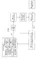
FIG. 2 is a block diagram illustrating details of an example data flow for detecting a fuel leak in a gas turbine engine, according to an embodiment. -
FIG. 3 is a flow diagram illustrating details of an example method for detecting a fuel leak in a gas turbine engine, according to an embodiment. - Illustrative embodiments will now be described more fully hereinafter with reference to the accompanying drawings, in which some, but not all embodiments are shown. The systems and methods may be embodied in many different forms and should not be construed as limited to the embodiments set forth herein; rather, these embodiments are provided so that this disclosure will satisfy applicable legal requirements. Like numbers refer to like elements throughout.
- Illustrative embodiments are directed to, among other things, systems and methods for detecting a fuel leak in a gas turbine engine. Certain embodiments may be directed towards determining a difference between a desired fuel flow and an actual fuel flow, wherein the difference indicates a fuel leak. For example, a control valve may be adjusted to correspond with a desired fuel flow. Next, an actual fuel flow may be determined based at least in part on an upstream pressure in a fuel manifold and one or more gas turbine engine parameters. It should be noted that adjusting the control valve adjusts the actual fuel flow and the upstream pressure in the fuel manifold. The desired fuel flow may be compared with the actual fuel flow such that a difference between the desired fuel flow and the actual fuel flow may be determined. In this manner, the difference between the desired fuel flow and the actual fuel flow may indicate a fuel leak. For example, detecting a fuel leak may be based at least in part on a predefined deviation between the desired fuel flow and the actual fuel flow that is indicative of a fuel leak.
- In some instances, based at least in part on the difference between the desired fuel flow and the actual fuel flow, at least one corrective action may be initiated to correct the fuel leak. The at least one corrective action may comprise modifying one or more fuel circuit splits, modifying one or more operation conditions, or shutting down one or more fuel circuits. For example, fuel may be redirected to the various circuits and/or completely cutoff.
- In certain aspects, the one or more gas turbine engine parameters may comprise one or more known parameters and/or one or more calculated parameters. For example, the one or more known parameters may comprise known fuel composition or known fuel circuit effective area. Other known parameters may include inlet temperature, inlet pressure, inlet humidity, inlet air composition, fuel pressure, or the like. The one or more calculated parameters may comprise a calculated downstream pressure or a calculated fuel temperature. Other calculated parameters may include a calculated downstream fuel temperature.
- Certain embodiments of the invention can provide a technical solution to detecting a fuel leak in a gas turbine engine. By detecting a leak and taking action against it, the opportunity for the leak to cause damage is drastically reduced, and the opportunity to correct the leak with minimal cost is increased. Without leak detection, fuel leaks may build, which eventually may create a flame-holding or flashback situation, where the air/fuel mixture ignites causing burning in areas of the combustor where burning is not desirable. Such undesirable conditions may lead to hardware damage and hot gas path parts damage. By detecting leaks early and taking action against them, the leakage location can be assessed, and hardware can be changed prior to any damage. As a result, outage and downtime may be shorter and less costly than if hardware fails due to undesirable burning caused by a leak.
- In certain embodiments, pressure sensors may be located in a fuel manifold of a fuel circuit and provide an upstream pressure. From the upstream pressure, along with a downstream pressure, fuel temperature, and fuel circuit effective area, an actual fuel flow can be calculated. In this manner, a desired fuel flow may be commanded by a control system (e.g., a controller) such that a fuel control valve is adjusted to achieve the desired fuel flow. The pressure in the fuel manifold changes as the fuel control valve is adjusted to achieve the desired fuel flow. As noted above, the actual fuel flow can be back calculated based on knowing the fuel manifold pressure and the other gas turbine parameters. The desired fuel flow and the calculated (i.e., actual) fuel flow can then be compared to each other to determine a relative difference. The difference between the desired fuel flow and the actual fuel flow can be used to determine if a leak has developed in the fuel circuits. If a leak is detected, the fuel manifold pressure will deviate from the expected, causing the calculated fuel flow to be different than predicted. Thus the relative deviation between the command (i.e., desired fuel flow) and the calculation (i.e., actual fuel flow) will increase.
- As noted, one or more of the parameters needed to calculate the actual flow are not parameters that are directly measured; instead, these parameters can be calculated (i.e., back calculated) based on many of the other gas turbine engine parameters that are measured. In some instances, the fuel temperature needs to be known, so any heat pickup or heat loss should be considered as well as how that fuel temperature changes with changing conditions.
-
FIG. 1 provides a schematic view of a gas turbine engine 10, according to an embodiment. As is known, the gas turbine engine 10 may include acompressor 15. Thecompressor 15 compresses an incoming flow ofair 20 and delivers the compressed flow ofair 20 to acombustor 25. Thecombustor 25 may include one or more fuel manifolds and one or more fuel circuits. Thecombustor 25 mixes the compressed flow ofair 20 with a pressurized flow offuel 30 and ignites the mixture to create a flow ofcombustion gases 35. Although only asingle combustor 25 is shown, the gas turbine engine 10 may include any number ofcombustors 25. The flow ofcombustion gases 35 is in turn delivered to aturbine 40. The flow ofcombustion gases 35 drives theturbine 40 so as to produce mechanical work. The mechanical work produced in theturbine 40 drives thecompressor 15 via ashaft 45 and anexternal load 50 such as an electrical generator and the like. - The gas turbine engine 10 may use natural gas, various types of syngas, and/or other types of fuels. The gas turbine engine 10 may have different configurations and may use other types of components. Moreover, other types of gas turbine engines also may be used herein. Multiple gas turbine engines, other types of turbines, and other types of power generation equipment also may be used herein together.
- Still referring to
FIG. 1 , thecompressor 15, thecombustor 25, theturbine 40, and the external load may all be in communication with acontroller 55. In this manner, thecontroller 55 may be configured to control, regulate, and/or monitor any number of components of the gas turbine engine 10. Thecontroller 55 may further be in communication with any number of sensors or monitoring devices associated with the gas turbine engine 10 as a whole or its individual components. Thecontroller 55 may be configured as any suitable computing device capable of implementing the disclosed features, and accompanying methods, such as, but not limited to, those described with reference toFIGS. 1-3 . By way of example and not limitation,suitable controllers 55 may include personal computers (PCs), servers, server farms, data centers, or any other device capable of storing and executing all or part of the disclosed features. - In one illustrative configuration, as depicted in
FIG. 2 , thecontroller 55 comprises at least amemory 102 and one or more processing units (or processor(s)) 104. The processor(s) 104 may be implemented as appropriate in hardware, software, firmware, or combinations thereof. Software or firmware implementations of the processor(s) 104 may include computer-executable or machine-executable instructions written in any suitable programming language to perform the various functions described. Moreover, the processor(s) 104 may be associated with a network, a server, a computer or a mobile device. -
Memory 102 may store program instructions that are loadable and executable on the processor(s) 104, as well as data generated during the execution of these programs. Depending on the configuration and type of thecontroller 55,memory 102 may be volatile (such as random access memory (RAM)) and/or non-volatile (such as read-only memory (ROM), flash memory, etc.). The computing device or server may also include additional removable storage 106 and/or non-removable storage 108 including, but not limited to, magnetic storage, optical disks, and/or tape storage. The disk drives and their associated computer-readable media may provide non-volatile storage of computer-readable instructions, data structures, program modules, and other data for the computing devices. In some implementations, thememory 102 may include multiple different types of memory, such as static random access memory (SRAM), dynamic random access memory (DRAM), or ROM. -
Memory 102, removable storage 106, and non-removable storage 108 are all examples of computer-readable storage media. For example, computer-readable storage media may include volatile and non-volatile, removable and non-removable media implemented in any method or technology for storage of information such as computer-readable instructions, data structures, program modules, or other data.Memory 102, removable storage 106, and non-removable storage 108 are all examples of computer storage media. Additional types of computer storage media that may be present include, but are not limited to, programmable random access memory (PRAM), SRAM, DRAM, RAM, ROM, electrically erasable programmable read-only memory (EEPROM), flash memory or other memory technology, compact disc read-only memory (CD-ROM), digital versatile discs (DVDs) or other optical storage, magnetic cassettes, magnetic tape, magnetic disk storage or other magnetic storage devices, or any other medium which can be used to store the desired information and which can be accessed by the server or other computing device. Combinations of any of above should also be included within the scope of computer-readable media. - Alternatively, computer-readable communication media may include computer-readable instructions, program modules, or other data transmitted within a data signal, such as a carrier wave, or other transmission.
- The
controller 55 may also contain communication connection(s) 110 that allow thecontroller 55 to communicate with a stored database, another computing device or server, user terminals, and/or other devices on a network. Thecontroller 55 may also include input device(s) 112, such as a keyboard, mouse, pen, voice input device, touch input device, etc., and output device(s) 114, such as a display, speakers, printer, etc. - Turning to the contents of the
memory 102 in more detail, thememory 102 may include an operating system and one or more application programs or services for implementing the features disclosed herein including aleak module 116. Theleak module 116 may be configured to determine a difference between a desiredfuel flow 120 and an actual fuel flow, wherein the difference indicates a fuel leak. For example, thecontroller 55 may determine a desiredfuel flow 120. In this manner, acontrol valve 118 may be adjusted to correspond with the desiredfuel flow 120. By adjusting thecontrol valve 118, the actual fuel flow is adjusted, which in turn changes the fuel manifold pressure 122. - After the desired
fuel flow 120 is determined and thefuel valve 118,fuel flow 120, and fuel manifold pressure 122 are adjusted accordingly, anactual fuel flow 130 may be determined atblock 124. Theactual fuel flow 130 may be determined atblock 124 based at least in part on an upstream pressure in a fuel manifold 122 and one or more gasturbine engine parameters 126. In certain aspects, the one or more gasturbine engine parameters 126 may comprise one or more known parameters and/or one or more calculated parameters. For example, the one or more known parameters may comprise known fuel composition and/or known fuel circuit effective area. Using the upstream pressure in a fuel manifold 122 and other known parameters, the one or more calculated parameters may be determined. The one or more calculated parameters may include a calculated downstream pressure and/or a calculated fuel temperature. Any number of algorithms may be used to determine the calculated downstream pressure and/or the calculated fuel temperature. - Next, the desired
fuel flow 120 may be compared with theactual fuel flow 130 such that a difference between the desired fuel flow and the actual fuel flow may be determined 128. In this manner, the difference between the desiredfuel flow 120 and theactual fuel flow 130 may indicate a fuel leak in the fuel circuit. For example, detecting a fuel leak may be based at least in part on a predefined deviation between the desiredfuel flow 120 and theactual fuel flow 130 that is indicative of a fuel leak in the fuel circuit. - Various instructions, methods, and techniques described herein may be considered in the general context of computer-executable instructions, such as program modules, executed by one or more computers or other devices. Generally, program modules include routines, programs, objects, components, data structures, etc., for performing particular tasks or implementing particular abstract data types. These program modules and the like may be executed as native code or may be downloaded and executed, such as in a virtual machine or other just-in-time compilation execution environment. Typically, the functionality of the program modules may be combined or distributed as desired in various embodiments. An implementation of these modules and techniques may be stored on some form of computer-readable storage media.
- The example system shown in
FIG. 2 is provided by way of example only. Numerous other operating environments, system architectures, and device configurations are possible. Accordingly, embodiments of the present disclosure should not be construed as being limited to any particular operating environment, system architecture, or device configuration. -
FIG. 3 illustrates an example flow diagram of amethod 300 for implementing other aspects for detecting a fuel leak in a gas turbine engine, as discussed above. In one example, theillustrative controller 55 ofFIGS. 1 and2 and/or one or more modules of theillustrative controller 55, alone or in combination, may perform the described operations of themethod 300. - In this particular implementation, the
method 300 may begin at block 302 ofFIG. 3 in which themethod 300 can include adjusting a control valve to correspond with a desired fuel flow. By adjusting the control valve to correspond with a desired fuel flow, the actual fuel flow and fuel manifold pressure are adjusted. Further, at block 304, themethod 300 can include determining an actual fuel flow based at least in part on an upstream pressure in a fuel manifold and one or more gas turbine engine parameters. In certain aspects, the one or more gas turbine engine parameters may comprise one or more known parameters and/or one or more calculated parameters. For example, the one or more known parameters may comprise known fuel composition and/or known fuel circuit effective area. Using the upstream pressure in a fuel manifold and other known parameters, the one or more calculated parameters may be determined. The one or more calculated parameters may include a calculated downstream pressure and/or a calculated fuel temperature. Atblock 306, themethod 300 can include comparing the desired fuel flow with the actual fuel flow. Atblock 308, themethod 300 may include determining a difference between the desired fuel flow and the actual fuel flow, wherein the difference indicates a fuel leak. For example, in some instances, the difference between the desired fuel flow and the actual fuel flow may be outside of a predefined deviation so as to indicate a fuel leak in the fuel circuit. Further, atblock 310, themethod 300 may include taking corrective action to mitigate risks associated with the fuel leak. For example, the at least one corrective action may comprise modifying one or more fuel circuit splits, modifying one or more operation conditions, or shutting down one or more fuel circuits. - Illustrative systems and methods are described for detecting fuel leaks in gas turbine engines. Some or all of these systems and methods may, but need not, be implemented at least partially by architectures such as those shown in
FIGS. 1 and2 above. Moreover, although embodiments have been described in relation to the detection of fuel leaks, it is understood that any fluid leak may be detected by the systems and methods described herein, including air, steam, water, air/fuel mixture, or the like. - Although embodiments have been described in language specific to structural features and/or methodological acts, it is to be understood that the disclosure is not necessarily limited to the specific features or acts described. Rather, the specific features and acts are disclosed as illustrative forms of implementing the embodiments.
- Various aspects and embodiments of the present invention are defined by the following numbered clauses:
- 1. A method of detecting a fluid leak in a gas turbine engine, comprising:
- adjusting a control valve to correspond with a desired fluid flow;
- determining an actual fluid flow based at least in part on an upstream pressure in a fluid manifold and one or more gas turbine engine parameters;
- comparing the desired fluid flow with the actual fluid flow;
- determining a difference between the desired fluid flow and the actual fluid flow, wherein the difference indicates a fluid leak; and
- based at least in part on the difference, initiating at least one corrective action to mitigate a risk associated with the fluid leak.
- 2. The method of clause 1, wherein the at least one corrective action comprises at least one of: modifying one or more fuel circuit splits, modifying one or more operation conditions, or shutting down one or more fuel circuits.
- 3. The method of any preceding clause, wherein the fluid is air.
- 4. The method of any preceding clause, wherein adjusting the control valve adjusts the actual fluid flow and the upstream pressure in the fluid manifold.
Claims (11)
- A method (300) of detecting a fuel leak in a gas turbine engine (10), comprising:adjusting (302) a control valve (118) to correspond with a desired fuel flow (120);determining (304) an actual fuel flow (130) based at least in part on an upstream pressure in a fuel manifold (122) and one or more gas turbine engine parameters (126);comparing (306) the desired fuel flow (120) with the actual fuel flow (130);
anddetermining (308) a difference between the desired fuel flow (120) and the actual fuel flow (130), wherein the difference indicates a fuel leak. - The method of claim 1, further comprising based at least in part on the difference, initiating (310) at least one corrective action.
- The method of claim 2, wherein the at least one corrective action comprises at least one of: modifying one or more fuel circuit splits, modifying one or more operation conditions, or shutting down one or more fuel circuits.
- The method of any of claims 1 to 3, wherein adjusting (302) the control valve (118) adjusts the actual fuel flow (130) and the upstream pressure in the fuel manifold (122).
- The method of any of claims 1 to 4, wherein the one or more gas turbine engine parameters (126) comprise at least one of: one or more known parameters or one or more calculated parameters.
- The method of claim 5, wherein the one or more known parameters comprise at least one of: known fuel composition or known fuel circuit effective area.
- The method of claim 5 or 6, wherein the one or more calculated parameters comprise at least one of: a calculated downstream pressure or a calculated fuel temperature.
- The method of any preceding claim, wherein determining (308) a difference between the desired fuel flow (120) and the actual fuel flow (130) is based at least in part on a predefined deviation.
- A computer program, comprising computer program code means adapted to perform the method of any of claims 1 to 8 when executed by computer.
- The computer program of claim 9, embodied on a computer-readable medium.
- A system for detecting fuel leaks in a gas turbine engine (10), comprising:a control valve (118); anda controller (55) comprising:at least one memory (102) that stores the computer program of claim 9 or 10; andat least one processor (104) configured to access the at least one memory (102), wherein the at least one processor (104) is configured to execute the computer program.
Applications Claiming Priority (1)
| Application Number | Priority Date | Filing Date | Title |
|---|---|---|---|
| US13/444,375 US9140189B2 (en) | 2012-04-11 | 2012-04-11 | Systems and methods for detecting fuel leaks in gas turbine engines |
Publications (3)
| Publication Number | Publication Date |
|---|---|
| EP2650491A2 true EP2650491A2 (en) | 2013-10-16 |
| EP2650491A3 EP2650491A3 (en) | 2017-10-25 |
| EP2650491B1 EP2650491B1 (en) | 2021-03-10 |
Family
ID=48092719
Family Applications (1)
| Application Number | Title | Priority Date | Filing Date |
|---|---|---|---|
| EP13162622.8A Active EP2650491B1 (en) | 2012-04-11 | 2013-04-05 | Systems and methods for detecting fuel leaks in gas turbine engines |
Country Status (5)
| Country | Link |
|---|---|
| US (1) | US9140189B2 (en) |
| EP (1) | EP2650491B1 (en) |
| JP (1) | JP6240396B2 (en) |
| CN (1) | CN103375272B (en) |
| RU (1) | RU2615303C2 (en) |
Cited By (2)
| Publication number | Priority date | Publication date | Assignee | Title |
|---|---|---|---|---|
| US9581088B2 (en) | 2013-07-23 | 2017-02-28 | Rolls-Royce Plc | System for performing staging control of a multi-stage combustor |
| IT201700073686A1 (en) * | 2017-06-30 | 2018-12-30 | Nuovo Pignone Tecnologie Srl | METHOD AND SYSTEM FOR THE SAFE START OF GAS TURBINES |
Families Citing this family (15)
| Publication number | Priority date | Publication date | Assignee | Title |
|---|---|---|---|---|
| EP2642086A1 (en) * | 2012-03-20 | 2013-09-25 | Alstom Technology Ltd | Gas turbine with fuel monitoring |
| US9500367B2 (en) | 2013-11-11 | 2016-11-22 | General Electric Company | Combustion casing manifold for high pressure air delivery to a fuel nozzle pilot system |
| FR3021350B1 (en) * | 2014-05-20 | 2016-07-01 | Snecma | METHOD FOR DETECTING FLUID LEAKAGE IN TURBOMACHINE AND FLUID DISPENSING SYSTEM |
| US10451509B2 (en) * | 2014-06-04 | 2019-10-22 | United Technologies Corporation | Method for determining a fault within a flow divider |
| DE102014119210A1 (en) * | 2014-12-19 | 2016-06-23 | Rolls-Royce Deutschland Ltd & Co Kg | Method for determining a fuel leak of a fuel system of an aircraft having at least two engines |
| US10240484B2 (en) * | 2015-11-06 | 2019-03-26 | General Electric Company | Gas accumulation detection and ventilation in a gas turbine enclosure |
| CN105645343B (en) * | 2016-02-29 | 2018-06-05 | 中国航空工业集团公司沈阳飞机设计研究所 | A kind of two-way pressure filling balance Control Scheme method |
| US10196928B2 (en) * | 2016-03-02 | 2019-02-05 | General Electric Company | Method and system for piping failure detection in a gas turbine bleeding air system |
| US10260425B2 (en) * | 2016-05-05 | 2019-04-16 | United Technologies Corporation | Leak detection, isolation and accommodation assembly for gas turbine engines |
| US10563594B2 (en) * | 2016-10-17 | 2020-02-18 | General Electric Company | Systems and methods for predicting fuel circuit leaks |
| CN111279174B (en) | 2017-10-23 | 2022-07-01 | 庞巴迪公司 | System and method for detecting fuel leaks in aircraft |
| FR3094086B1 (en) * | 2019-03-19 | 2021-03-19 | Safran Aircraft Engines | Method for monitoring the operating state of a hydromechanical unit |
| CN110657037B (en) * | 2019-09-29 | 2021-12-17 | 潍柴西港新能源动力有限公司 | Method for detecting leakage of gas supply system of natural gas engine |
| US20210285384A1 (en) * | 2020-03-16 | 2021-09-16 | Hamilton Sundstrand Corporation | High accuracy fuel system |
| US11519808B2 (en) * | 2020-10-30 | 2022-12-06 | General Electric Company | Fluid monitoring system |
Family Cites Families (18)
| Publication number | Priority date | Publication date | Assignee | Title |
|---|---|---|---|---|
| JPS619246Y2 (en) * | 1979-01-08 | 1986-03-24 | ||
| JPS59155533A (en) * | 1983-02-25 | 1984-09-04 | Toshiba Corp | Gas turbine plant |
| JPS61241425A (en) * | 1985-04-17 | 1986-10-27 | Hitachi Ltd | Fuel gas controlling method of gas turbine and controller |
| JP2631597B2 (en) * | 1992-04-10 | 1997-07-16 | 川崎重工業株式会社 | Gas fuel combustion control method |
| AU730820B2 (en) * | 1995-12-26 | 2001-03-15 | Kabushiki Kaisha Toshiba | Fuel supply apparatus for gas turbine and control unit for the same |
| JPH10110631A (en) * | 1996-10-08 | 1998-04-28 | Hitachi Ltd | Gas turbine fuel manifold system |
| US6438963B1 (en) * | 2000-08-31 | 2002-08-27 | General Electric Company | Liquid fuel and water injection purge systems and method for a gas turbine having a three-way purge valve |
| JP2004232993A (en) * | 2003-01-31 | 2004-08-19 | Matsushita Electric Ind Co Ltd | Fuel gas firing equipment |
| RU2240263C1 (en) * | 2003-06-10 | 2004-11-20 | Открытое акционерное общество "ОКБ Сухого" | Method for notification of crew about fuel leakage on aircraft during flight |
| DE10351893A1 (en) * | 2003-11-06 | 2005-06-09 | Robert Bosch Gmbh | Method for operating an internal combustion engine |
| RU2266529C2 (en) * | 2004-01-29 | 2005-12-20 | Мугинштейн Лев Александрович | Method of checking condition of vehicle power plant |
| CN100449839C (en) * | 2004-03-17 | 2009-01-07 | 丰田自动车株式会社 | Device and method for detecting gas leakage |
| DE102004040924B4 (en) | 2004-08-24 | 2019-04-11 | Robert Bosch Gmbh | Method and device for monitoring pressure sensors in the exhaust gas system |
| JP4119908B2 (en) * | 2005-09-14 | 2008-07-16 | 三菱重工業株式会社 | Combustion control device for gas turbine |
| US7549293B2 (en) * | 2006-02-15 | 2009-06-23 | General Electric Company | Pressure control method to reduce gas turbine fuel supply pressure requirements |
| US7739004B2 (en) * | 2006-11-29 | 2010-06-15 | The Boeing Company | Automatic engine fuel flow monitoring and alerting fuel leak detection method |
| RU95150U1 (en) * | 2010-03-04 | 2010-06-10 | Эмиль Беняминович Арзангулян | SYSTEM OF ACCOUNTING FUEL CONSUMPTION AT AUTONOMOUS FUEL SUPPLY OF OBJECTS |
| JP5495938B2 (en) * | 2010-05-20 | 2014-05-21 | 三菱重工業株式会社 | Gas turbine fuel control mechanism and gas turbine |
-
2012
- 2012-04-11 US US13/444,375 patent/US9140189B2/en active Active
-
2013
- 2013-04-05 EP EP13162622.8A patent/EP2650491B1/en active Active
- 2013-04-09 JP JP2013080880A patent/JP6240396B2/en active Active
- 2013-04-10 RU RU2013115864A patent/RU2615303C2/en active
- 2013-04-11 CN CN201310124970.8A patent/CN103375272B/en active Active
Non-Patent Citations (1)
| Title |
|---|
| None |
Cited By (5)
| Publication number | Priority date | Publication date | Assignee | Title |
|---|---|---|---|---|
| US9581088B2 (en) | 2013-07-23 | 2017-02-28 | Rolls-Royce Plc | System for performing staging control of a multi-stage combustor |
| IT201700073686A1 (en) * | 2017-06-30 | 2018-12-30 | Nuovo Pignone Tecnologie Srl | METHOD AND SYSTEM FOR THE SAFE START OF GAS TURBINES |
| WO2019002572A1 (en) * | 2017-06-30 | 2019-01-03 | Nuovo Pignone Tecnologie Srl | Method and system for safe gas turbine startup |
| AU2018293753B2 (en) * | 2017-06-30 | 2021-02-25 | Nuovo Pignone Tecnologie - S.r.l | Method and system for safe gas turbine startup |
| US11333075B2 (en) | 2017-06-30 | 2022-05-17 | Nuovo Pignone Tecnologie Srl | Method and system for safe gas turbine startup |
Also Published As
| Publication number | Publication date |
|---|---|
| JP2013217376A (en) | 2013-10-24 |
| CN103375272A (en) | 2013-10-30 |
| RU2615303C2 (en) | 2017-04-04 |
| US9140189B2 (en) | 2015-09-22 |
| EP2650491A3 (en) | 2017-10-25 |
| RU2013115864A (en) | 2014-10-20 |
| EP2650491B1 (en) | 2021-03-10 |
| JP6240396B2 (en) | 2017-11-29 |
| CN103375272B (en) | 2016-08-03 |
| US20130269364A1 (en) | 2013-10-17 |
Similar Documents
| Publication | Publication Date | Title |
|---|---|---|
| US9140189B2 (en) | Systems and methods for detecting fuel leaks in gas turbine engines | |
| US20170356344A1 (en) | Systems and Methods to Control Combustion Dynamic Frequencies | |
| US9476361B2 (en) | Systems and methods for control of operating life of a gas turbine | |
| JP5583455B2 (en) | System and method for providing surge protection to turbine components | |
| JP6114511B2 (en) | System and method for self-tuning a combustion system of a gas turbine | |
| US9297315B2 (en) | Systems and methods for determining a target exhaust temperature for a gas turbine | |
| KR102324007B1 (en) | Bulk flame temperature regulator for dry low emission engines | |
| JP2012026449A (en) | Method for controlling fuel split to gas turbine combustor | |
| US10563594B2 (en) | Systems and methods for predicting fuel circuit leaks | |
| KR20180040105A (en) | Systems and methods to control performance via control of compressor oll protection actions | |
| US9726085B2 (en) | Method for controlling a gas turbine group | |
| JP2014132173A (en) | Gas turbine and method of controlling gas turbine at part-load condition | |
| EP3511537B1 (en) | Gas turbine cogeneration system and operation mode change method therefor | |
| US9500136B2 (en) | Systems and methods for generating variable ramp rates for turbomachinery | |
| JP5537887B2 (en) | Method and system for operating a turbomachine having a non-choke valve | |
| US20190063332A1 (en) | Systems and methods for nox prediction in a power plant | |
| JP2017096265A (en) | System and method for determining fuel splits for gas turbine | |
| JP2013221735A (en) | Method, system, and apparatus for transition piece contouring | |
| US9464534B2 (en) | Turbine purge flow control system and related method of operation | |
| JP2022044539A (en) | Modeling and control of gas cycle power plant operation by varying split load for multiple gas turbines | |
| JP2017141728A (en) | Gas turbine control device, gas turbine control method and program | |
| CN108119237B (en) | Model-free combustion power auto-tuning | |
| US20160215703A1 (en) | Control system for can-to-can variation in combustor system and related method | |
| JP2023044719A (en) | System and method for non-model based control utilizing turbine exit mach number surrogate |
Legal Events
| Date | Code | Title | Description |
|---|---|---|---|
| PUAI | Public reference made under article 153(3) epc to a published international application that has entered the european phase |
Free format text: ORIGINAL CODE: 0009012 |
|
| AK | Designated contracting states |
Kind code of ref document: A2 Designated state(s): AL AT BE BG CH CY CZ DE DK EE ES FI FR GB GR HR HU IE IS IT LI LT LU LV MC MK MT NL NO PL PT RO RS SE SI SK SM TR |
|
| AX | Request for extension of the european patent |
Extension state: BA ME |
|
| PUAL | Search report despatched |
Free format text: ORIGINAL CODE: 0009013 |
|
| AK | Designated contracting states |
Kind code of ref document: A3 Designated state(s): AL AT BE BG CH CY CZ DE DK EE ES FI FR GB GR HR HU IE IS IT LI LT LU LV MC MK MT NL NO PL PT RO RS SE SI SK SM TR |
|
| AX | Request for extension of the european patent |
Extension state: BA ME |
|
| RIC1 | Information provided on ipc code assigned before grant |
Ipc: F02C 9/28 20060101ALI20170921BHEP Ipc: F02D 41/22 20060101ALN20170921BHEP Ipc: F01D 21/14 20060101AFI20170921BHEP Ipc: F02C 7/232 20060101ALI20170921BHEP Ipc: F02C 7/22 20060101ALI20170921BHEP |
|
| 17P | Request for examination filed |
Effective date: 20180425 |
|
| RBV | Designated contracting states (corrected) |
Designated state(s): AL AT BE BG CH CY CZ DE DK EE ES FI FR GB GR HR HU IE IS IT LI LT LU LV MC MK MT NL NO PL PT RO RS SE SI SK SM TR |
|
| STAA | Information on the status of an ep patent application or granted ep patent |
Free format text: STATUS: EXAMINATION IS IN PROGRESS |
|
| 17Q | First examination report despatched |
Effective date: 20190220 |
|
| RIC1 | Information provided on ipc code assigned before grant |
Ipc: F01D 21/14 20060101AFI20200909BHEP Ipc: F02C 9/28 20060101ALI20200909BHEP Ipc: F02C 7/22 20060101ALI20200909BHEP Ipc: F02C 7/232 20060101ALI20200909BHEP Ipc: F02D 41/22 20060101ALN20200909BHEP |
|
| GRAP | Despatch of communication of intention to grant a patent |
Free format text: ORIGINAL CODE: EPIDOSNIGR1 |
|
| STAA | Information on the status of an ep patent application or granted ep patent |
Free format text: STATUS: GRANT OF PATENT IS INTENDED |
|
| RIC1 | Information provided on ipc code assigned before grant |
Ipc: F01D 21/14 20060101AFI20200916BHEP Ipc: F02C 9/28 20060101ALI20200916BHEP Ipc: F02C 7/22 20060101ALI20200916BHEP Ipc: F02D 41/22 20060101ALN20200916BHEP Ipc: F02C 7/232 20060101ALI20200916BHEP |
|
| INTG | Intention to grant announced |
Effective date: 20201016 |
|
| GRAS | Grant fee paid |
Free format text: ORIGINAL CODE: EPIDOSNIGR3 |
|
| GRAA | (expected) grant |
Free format text: ORIGINAL CODE: 0009210 |
|
| STAA | Information on the status of an ep patent application or granted ep patent |
Free format text: STATUS: THE PATENT HAS BEEN GRANTED |
|
| AK | Designated contracting states |
Kind code of ref document: B1 Designated state(s): AL AT BE BG CH CY CZ DE DK EE ES FI FR GB GR HR HU IE IS IT LI LT LU LV MC MK MT NL NO PL PT RO RS SE SI SK SM TR |
|
| REG | Reference to a national code |
Ref country code: GB Ref legal event code: FG4D |
|
| REG | Reference to a national code |
Ref country code: AT Ref legal event code: REF Ref document number: 1370016 Country of ref document: AT Kind code of ref document: T Effective date: 20210315 Ref country code: CH Ref legal event code: EP |
|
| REG | Reference to a national code |
Ref country code: IE Ref legal event code: FG4D |
|
| REG | Reference to a national code |
Ref country code: DE Ref legal event code: R096 Ref document number: 602013076138 Country of ref document: DE |
|
| REG | Reference to a national code |
Ref country code: LT Ref legal event code: MG9D |
|
| PG25 | Lapsed in a contracting state [announced via postgrant information from national office to epo] |
Ref country code: LT Free format text: LAPSE BECAUSE OF FAILURE TO SUBMIT A TRANSLATION OF THE DESCRIPTION OR TO PAY THE FEE WITHIN THE PRESCRIBED TIME-LIMIT Effective date: 20210310 Ref country code: HR Free format text: LAPSE BECAUSE OF FAILURE TO SUBMIT A TRANSLATION OF THE DESCRIPTION OR TO PAY THE FEE WITHIN THE PRESCRIBED TIME-LIMIT Effective date: 20210310 Ref country code: FI Free format text: LAPSE BECAUSE OF FAILURE TO SUBMIT A TRANSLATION OF THE DESCRIPTION OR TO PAY THE FEE WITHIN THE PRESCRIBED TIME-LIMIT Effective date: 20210310 Ref country code: GR Free format text: LAPSE BECAUSE OF FAILURE TO SUBMIT A TRANSLATION OF THE DESCRIPTION OR TO PAY THE FEE WITHIN THE PRESCRIBED TIME-LIMIT Effective date: 20210611 Ref country code: NO Free format text: LAPSE BECAUSE OF FAILURE TO SUBMIT A TRANSLATION OF THE DESCRIPTION OR TO PAY THE FEE WITHIN THE PRESCRIBED TIME-LIMIT Effective date: 20210610 Ref country code: BG Free format text: LAPSE BECAUSE OF FAILURE TO SUBMIT A TRANSLATION OF THE DESCRIPTION OR TO PAY THE FEE WITHIN THE PRESCRIBED TIME-LIMIT Effective date: 20210610 |
|
| REG | Reference to a national code |
Ref country code: AT Ref legal event code: MK05 Ref document number: 1370016 Country of ref document: AT Kind code of ref document: T Effective date: 20210310 |
|
| REG | Reference to a national code |
Ref country code: NL Ref legal event code: MP Effective date: 20210310 |
|
| PG25 | Lapsed in a contracting state [announced via postgrant information from national office to epo] |
Ref country code: SE Free format text: LAPSE BECAUSE OF FAILURE TO SUBMIT A TRANSLATION OF THE DESCRIPTION OR TO PAY THE FEE WITHIN THE PRESCRIBED TIME-LIMIT Effective date: 20210310 Ref country code: RS Free format text: LAPSE BECAUSE OF FAILURE TO SUBMIT A TRANSLATION OF THE DESCRIPTION OR TO PAY THE FEE WITHIN THE PRESCRIBED TIME-LIMIT Effective date: 20210310 Ref country code: LV Free format text: LAPSE BECAUSE OF FAILURE TO SUBMIT A TRANSLATION OF THE DESCRIPTION OR TO PAY THE FEE WITHIN THE PRESCRIBED TIME-LIMIT Effective date: 20210310 |
|
| PG25 | Lapsed in a contracting state [announced via postgrant information from national office to epo] |
Ref country code: NL Free format text: LAPSE BECAUSE OF FAILURE TO SUBMIT A TRANSLATION OF THE DESCRIPTION OR TO PAY THE FEE WITHIN THE PRESCRIBED TIME-LIMIT Effective date: 20210310 |
|
| PG25 | Lapsed in a contracting state [announced via postgrant information from national office to epo] |
Ref country code: CZ Free format text: LAPSE BECAUSE OF FAILURE TO SUBMIT A TRANSLATION OF THE DESCRIPTION OR TO PAY THE FEE WITHIN THE PRESCRIBED TIME-LIMIT Effective date: 20210310 Ref country code: EE Free format text: LAPSE BECAUSE OF FAILURE TO SUBMIT A TRANSLATION OF THE DESCRIPTION OR TO PAY THE FEE WITHIN THE PRESCRIBED TIME-LIMIT Effective date: 20210310 Ref country code: SM Free format text: LAPSE BECAUSE OF FAILURE TO SUBMIT A TRANSLATION OF THE DESCRIPTION OR TO PAY THE FEE WITHIN THE PRESCRIBED TIME-LIMIT Effective date: 20210310 Ref country code: AT Free format text: LAPSE BECAUSE OF FAILURE TO SUBMIT A TRANSLATION OF THE DESCRIPTION OR TO PAY THE FEE WITHIN THE PRESCRIBED TIME-LIMIT Effective date: 20210310 |
|
| PG25 | Lapsed in a contracting state [announced via postgrant information from national office to epo] |
Ref country code: IS Free format text: LAPSE BECAUSE OF FAILURE TO SUBMIT A TRANSLATION OF THE DESCRIPTION OR TO PAY THE FEE WITHIN THE PRESCRIBED TIME-LIMIT Effective date: 20210710 Ref country code: RO Free format text: LAPSE BECAUSE OF FAILURE TO SUBMIT A TRANSLATION OF THE DESCRIPTION OR TO PAY THE FEE WITHIN THE PRESCRIBED TIME-LIMIT Effective date: 20210310 Ref country code: ES Free format text: LAPSE BECAUSE OF FAILURE TO SUBMIT A TRANSLATION OF THE DESCRIPTION OR TO PAY THE FEE WITHIN THE PRESCRIBED TIME-LIMIT Effective date: 20210310 Ref country code: PL Free format text: LAPSE BECAUSE OF FAILURE TO SUBMIT A TRANSLATION OF THE DESCRIPTION OR TO PAY THE FEE WITHIN THE PRESCRIBED TIME-LIMIT Effective date: 20210310 Ref country code: PT Free format text: LAPSE BECAUSE OF FAILURE TO SUBMIT A TRANSLATION OF THE DESCRIPTION OR TO PAY THE FEE WITHIN THE PRESCRIBED TIME-LIMIT Effective date: 20210712 Ref country code: SK Free format text: LAPSE BECAUSE OF FAILURE TO SUBMIT A TRANSLATION OF THE DESCRIPTION OR TO PAY THE FEE WITHIN THE PRESCRIBED TIME-LIMIT Effective date: 20210310 |
|
| REG | Reference to a national code |
Ref country code: DE Ref legal event code: R097 Ref document number: 602013076138 Country of ref document: DE |
|
| PG25 | Lapsed in a contracting state [announced via postgrant information from national office to epo] |
Ref country code: LU Free format text: LAPSE BECAUSE OF NON-PAYMENT OF DUE FEES Effective date: 20210405 |
|
| PLBE | No opposition filed within time limit |
Free format text: ORIGINAL CODE: 0009261 |
|
| STAA | Information on the status of an ep patent application or granted ep patent |
Free format text: STATUS: NO OPPOSITION FILED WITHIN TIME LIMIT |
|
| REG | Reference to a national code |
Ref country code: BE Ref legal event code: MM Effective date: 20210430 |
|
| PG25 | Lapsed in a contracting state [announced via postgrant information from national office to epo] |
Ref country code: DK Free format text: LAPSE BECAUSE OF FAILURE TO SUBMIT A TRANSLATION OF THE DESCRIPTION OR TO PAY THE FEE WITHIN THE PRESCRIBED TIME-LIMIT Effective date: 20210310 Ref country code: MC Free format text: LAPSE BECAUSE OF FAILURE TO SUBMIT A TRANSLATION OF THE DESCRIPTION OR TO PAY THE FEE WITHIN THE PRESCRIBED TIME-LIMIT Effective date: 20210310 Ref country code: LI Free format text: LAPSE BECAUSE OF NON-PAYMENT OF DUE FEES Effective date: 20210430 Ref country code: AL Free format text: LAPSE BECAUSE OF FAILURE TO SUBMIT A TRANSLATION OF THE DESCRIPTION OR TO PAY THE FEE WITHIN THE PRESCRIBED TIME-LIMIT Effective date: 20210310 Ref country code: CH Free format text: LAPSE BECAUSE OF NON-PAYMENT OF DUE FEES Effective date: 20210430 |
|
| 26N | No opposition filed |
Effective date: 20211213 |
|
| GBPC | Gb: european patent ceased through non-payment of renewal fee |
Effective date: 20210610 |
|
| PG25 | Lapsed in a contracting state [announced via postgrant information from national office to epo] |
Ref country code: SI Free format text: LAPSE BECAUSE OF FAILURE TO SUBMIT A TRANSLATION OF THE DESCRIPTION OR TO PAY THE FEE WITHIN THE PRESCRIBED TIME-LIMIT Effective date: 20210310 |
|
| PG25 | Lapsed in a contracting state [announced via postgrant information from national office to epo] |
Ref country code: IE Free format text: LAPSE BECAUSE OF NON-PAYMENT OF DUE FEES Effective date: 20210405 Ref country code: GB Free format text: LAPSE BECAUSE OF NON-PAYMENT OF DUE FEES Effective date: 20210610 |
|
| PG25 | Lapsed in a contracting state [announced via postgrant information from national office to epo] |
Ref country code: IS Free format text: LAPSE BECAUSE OF FAILURE TO SUBMIT A TRANSLATION OF THE DESCRIPTION OR TO PAY THE FEE WITHIN THE PRESCRIBED TIME-LIMIT Effective date: 20210710 Ref country code: FR Free format text: LAPSE BECAUSE OF NON-PAYMENT OF DUE FEES Effective date: 20210510 |
|
| PG25 | Lapsed in a contracting state [announced via postgrant information from national office to epo] |
Ref country code: BE Free format text: LAPSE BECAUSE OF NON-PAYMENT OF DUE FEES Effective date: 20210430 |
|
| PG25 | Lapsed in a contracting state [announced via postgrant information from national office to epo] |
Ref country code: HU Free format text: LAPSE BECAUSE OF FAILURE TO SUBMIT A TRANSLATION OF THE DESCRIPTION OR TO PAY THE FEE WITHIN THE PRESCRIBED TIME-LIMIT; INVALID AB INITIO Effective date: 20130405 |
|
| P01 | Opt-out of the competence of the unified patent court (upc) registered |
Effective date: 20230522 |
|
| PG25 | Lapsed in a contracting state [announced via postgrant information from national office to epo] |
Ref country code: CY Free format text: LAPSE BECAUSE OF FAILURE TO SUBMIT A TRANSLATION OF THE DESCRIPTION OR TO PAY THE FEE WITHIN THE PRESCRIBED TIME-LIMIT Effective date: 20210310 |
|
| REG | Reference to a national code |
Ref country code: DE Ref legal event code: R081 Ref document number: 602013076138 Country of ref document: DE Owner name: GENERAL ELECTRIC TECHNOLOGY GMBH, CH Free format text: FORMER OWNER: GENERAL ELECTRIC COMPANY, SCHENECTADY, NY, US |
|
| PG25 | Lapsed in a contracting state [announced via postgrant information from national office to epo] |
Ref country code: MK Free format text: LAPSE BECAUSE OF FAILURE TO SUBMIT A TRANSLATION OF THE DESCRIPTION OR TO PAY THE FEE WITHIN THE PRESCRIBED TIME-LIMIT Effective date: 20210310 |
|
| PGFP | Annual fee paid to national office [announced via postgrant information from national office to epo] |
Ref country code: IT Payment date: 20240320 Year of fee payment: 12 |
|
| PGFP | Annual fee paid to national office [announced via postgrant information from national office to epo] |
Ref country code: DE Payment date: 20240320 Year of fee payment: 12 |