EP2650480A2 - Übergangsstück für eine Gasturbinenanlage, zugehörige System und Verfahren - Google Patents
Übergangsstück für eine Gasturbinenanlage, zugehörige System und Verfahren Download PDFInfo
- Publication number
- EP2650480A2 EP2650480A2 EP13163218.4A EP13163218A EP2650480A2 EP 2650480 A2 EP2650480 A2 EP 2650480A2 EP 13163218 A EP13163218 A EP 13163218A EP 2650480 A2 EP2650480 A2 EP 2650480A2
- Authority
- EP
- European Patent Office
- Prior art keywords
- transition piece
- cross sectional
- sectional area
- constant slope
- aft
- Prior art date
- Legal status (The legal status is an assumption and is not a legal conclusion. Google has not performed a legal analysis and makes no representation as to the accuracy of the status listed.)
- Withdrawn
Links
- 230000007704 transition Effects 0.000 title claims abstract description 99
- 238000000034 method Methods 0.000 title claims abstract description 22
- 230000008859 change Effects 0.000 claims abstract description 11
- 238000005259 measurement Methods 0.000 claims description 11
- 230000009467 reduction Effects 0.000 abstract description 3
- 238000003860 storage Methods 0.000 description 11
- 230000003287 optical effect Effects 0.000 description 8
- 239000007789 gas Substances 0.000 description 7
- 238000004891 communication Methods 0.000 description 4
- 238000012545 processing Methods 0.000 description 4
- 230000005055 memory storage Effects 0.000 description 3
- 230000006855 networking Effects 0.000 description 3
- 238000012360 testing method Methods 0.000 description 3
- 238000004458 analytical method Methods 0.000 description 2
- 239000000567 combustion gas Substances 0.000 description 2
- 230000006866 deterioration Effects 0.000 description 2
- 238000010586 diagram Methods 0.000 description 2
- 238000005516 engineering process Methods 0.000 description 2
- 238000002474 experimental method Methods 0.000 description 2
- 239000000446 fuel Substances 0.000 description 2
- 239000000203 mixture Substances 0.000 description 2
- 230000003647 oxidation Effects 0.000 description 2
- 238000007254 oxidation reaction Methods 0.000 description 2
- 230000002093 peripheral effect Effects 0.000 description 2
- 238000002485 combustion reaction Methods 0.000 description 1
- 238000005336 cracking Methods 0.000 description 1
- 238000013461 design Methods 0.000 description 1
- 230000000694 effects Effects 0.000 description 1
- 230000005611 electricity Effects 0.000 description 1
- 230000006870 function Effects 0.000 description 1
- 238000004519 manufacturing process Methods 0.000 description 1
- 239000000463 material Substances 0.000 description 1
- 239000002184 metal Substances 0.000 description 1
- 230000002028 premature Effects 0.000 description 1
- 230000008439 repair process Effects 0.000 description 1
- 238000012546 transfer Methods 0.000 description 1
Images


Classifications
-
- F—MECHANICAL ENGINEERING; LIGHTING; HEATING; WEAPONS; BLASTING
- F01—MACHINES OR ENGINES IN GENERAL; ENGINE PLANTS IN GENERAL; STEAM ENGINES
- F01D—NON-POSITIVE DISPLACEMENT MACHINES OR ENGINES, e.g. STEAM TURBINES
- F01D9/00—Stators
- F01D9/02—Nozzles; Nozzle boxes; Stator blades; Guide conduits, e.g. individual nozzles
- F01D9/023—Transition ducts between combustor cans and first stage of the turbine in gas-turbine engines; their cooling or sealings
-
- F—MECHANICAL ENGINEERING; LIGHTING; HEATING; WEAPONS; BLASTING
- F05—INDEXING SCHEMES RELATING TO ENGINES OR PUMPS IN VARIOUS SUBCLASSES OF CLASSES F01-F04
- F05D—INDEXING SCHEME FOR ASPECTS RELATING TO NON-POSITIVE-DISPLACEMENT MACHINES OR ENGINES, GAS-TURBINES OR JET-PROPULSION PLANTS
- F05D2250/00—Geometry
- F05D2250/50—Inlet or outlet
-
- Y—GENERAL TAGGING OF NEW TECHNOLOGICAL DEVELOPMENTS; GENERAL TAGGING OF CROSS-SECTIONAL TECHNOLOGIES SPANNING OVER SEVERAL SECTIONS OF THE IPC; TECHNICAL SUBJECTS COVERED BY FORMER USPC CROSS-REFERENCE ART COLLECTIONS [XRACs] AND DIGESTS
- Y10—TECHNICAL SUBJECTS COVERED BY FORMER USPC
- Y10T—TECHNICAL SUBJECTS COVERED BY FORMER US CLASSIFICATION
- Y10T29/00—Metal working
- Y10T29/49—Method of mechanical manufacture
- Y10T29/49316—Impeller making
- Y10T29/4932—Turbomachine making
- Y10T29/49323—Assembling fluid flow directing devices, e.g., stators, diaphragms, nozzles
Definitions
- the subject matter disclosed herein relates generally to combustion systems and more specifically hot gas flow.
- a plurality of combustors are arranged in a generally annular array about the engine.
- the combustors receive pressurized air from the engine's compressor, add fuel to create a fuel and air mixture, and combust the mixture to produce hot gases.
- the hot gases exiting the combustors are utilized to turn a turbine, which is coupled to a shaft that drives a generator for generating electricity.
- the hot combustion gas is conveyed from the combustor liner to the turbine by a transition piece or duct.
- the hot combustion gas flowing through the transition piece subjects the duct structure to very high temperatures and can lead to premature deterioration that requires repair and replacement of the transition ducts.
- a significant crack or other deterioration in a single area of an otherwise relatively undamaged transition piece may have a significant impact on gas turbine performance and may require replacement of the entire transition piece.
- a method determines an aft end cross sectional area for a transition piece and a forward end cross sectional area for the transition piece.
- the transition piece may be fabricated based on a constant slope of cross sectional area change between the aft end and the forward end.
- a system has a first processor and a first memory.
- the first memory may be communicatively coupled to the first processor said first memory having stored therein computer-readable instructions that, if executed by the first processor, cause the processor to perform operations comprising determining an aft end cross sectional area for a transition piece; determining a forward end cross sectional area based on the aft end cross sectional area for the transition piece; determining the constant slope of cross sectional area change between the aft end and the forward end; and fabricating the transition piece based on the constant slope of cross sectional area.
- a transition piece comprises a cross sectional area along the length of the transition piece that stays within +/- 3% of a constant slope cross section area, wherein the constant slope cross sectional area is based on an aft end cross sectional area measurement and a corresponding forward end cross sectional area measurement at a respective length.
- FIG. 1 is an exemplary illustration of a transition piece 100.
- Transition piece 100 has a forward (inlet) end 105 and an aft (outlet) end 110. Hot gases flow into inlet 105 and flow through the length of transition piece 100. The hot gases exit transition piece 100 at outlet 110.
- the life limiting area of a transition piece often has higher temperatures placed on it than other areas of the transition piece. These higher temperatures may cause a higher strain range for every start to stop cycle of the turbine. Over time, these strain cycles may accumulate and become the transition piece's life limit. These higher temperatures may also cause oxidation of the transition piece material. Over time, this oxidation may accumulate and become the transition piece's life limit. As stated herein, regardless of the relatively undamaged nature of the other portions of the transition piece, the entire transition piece is replaced when significant damage (e.g., cracking) is done to a particular area of the transition piece.
- significant damage e.g., cracking
- FIG. 2 is an exemplary illustration of a transition piece 200.
- An inlet cross sectional area may be taken at 205 and an outlet cross sectional area may be taken at 210.
- the percentage decrease of the inlet cross sectional area at 205 compared to the outlet cross sectional area at 210 would conform to the 15% rule of thumb.
- the middle section 215 has a cross sectional area that diverges substantially before reaching the final 15% rule of thumb percentage.
- Figure 3 is an exemplary graph that illustrates the change of the cross sectional areas of transition pieces from aft to forward end.
- Axis y 302 denotes the cross sectional area of a transition piece and axis x 303 denotes the length of the transition piece from aft end to fwd end.
- Line 305 is a line that has a constant slope, wherein the cross sectional area changes constantly along the length from aft to forward end.
- the ideal or reference line 305 (hereinafter reference line) may be determined using standard algebraic equations and the like once the aft and fwd end cross sectional area and length are determined.
- Curve 310 is a curve that is out of the discussed +/- 3% range along the length of the transition piece.
- point 311 shows that the transition piece represented by curve 310 has an approximate cross sectional area of 208 at length 15, while the transition piece represented by reference line 305 has an approximate cross sectional area of 188 at length 15.
- 311 of curve 310 diverges by approximately 10 percent at the same length of the reference line 305.
- Curve 315 is a curve that is within the discussed +/- 3% range along the length of the transition piece.
- point 316 shows that the transition piece represented by curve 315 has an approximate cross sectional area of 192 at length 15, while the transition piece represented by line 305 has an approximate cross sectional area of 188 at length 15.
- point 316 diverges by approximately 2.1 % from the reference line 305.
- a computer generated or physical manifestation of a transition piece may be created based on a predetermined calculated constant change cross sectional area reference line.
- An example of a physical manifestation may be a physical transition piece mold that conforms to the reference line with +/- 3% divergence in cross sectional area. Measurements of cross sectional area may be taken at every 1/10 interval of the length of the entire transition piece. More frequent measurements may be taken for more data points and better results when creating a transition piece.
- Figure 4 illustrates a non-limiting, exemplary method of implementing transition piece cross sectional area convergence as disclosed herein.
- Method 400 may be performed by computing equipment including mobile devices (e.g., tablet computers), servers, or any other device that can execute computing functions.
- mobile devices e.g., tablet computers
- servers or any other device that can execute computing functions.
- a transition piece aft shape and end cross sectional area may be determined.
- the aft end cross sectional area determination may be based on characteristics of a corresponding stage one nozzle (SIN).
- the transition piece fwd end shape and cross sectional area may be determined.
- the fwd end cross sectional area may be based on the aft end cross sectional area.
- the constant slope of cross sectional area change along the length of the transition piece between aft end and fwd end may be determined.
- a transition piece may be created based on the constant slope of the cross sectional area and remaining within a +/- 3% tolerance level.
- the technical effect of the method is the fabrication of a physical manifestation (e.g., metal) of a transition piece or the creation of a computer generated representation of a transition piece in a turbine system.
- Tests of the transition piece may be done using physical transition pieces with test equipment, computer specifications of a transition piece and corresponding computer analysis, or the like. Tests may be done on a particular transition piece design, such as a transition piece made for one or more generator models, and implemented in a physical form or digital form. Although measurements are described as being taken at the forward and aft end, it is reasonable to take measurements within an approximate area of either end.
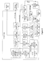
- FIG. 5 and the following discussion are intended to provide a brief general description of a suitable computing environment in which the methods and systems disclosed herein and/or portions thereof may be implemented.
- the methods and systems disclosed herein may be described in the general context of computer-executable instructions, such as program modules, being executed by a computer, such as a client workstation, server or personal computer.
- program modules include routines, programs, objects, components, data structures and the like that perform particular tasks or implement particular abstract data types.
- the methods and systems disclosed herein and/or portions thereof may be practiced with other computer system configurations, including hand-held devices, multi-processor systems, microprocessor-based or programmable consumer electronics, network PCs, minicomputers, mainframe computers and the like.
- the methods and systems disclosed herein may also be practiced in distributed computing environments where tasks are performed by remote processing devices that are linked through a communications network.
- program modules may be located in both local and remote memory storage devices.
- FIG. 5 is a block diagram representing a general purpose computer system in which aspects of the methods and systems disclosed herein and/or portions thereof may be incorporated.
- the exemplary general purpose computing system includes a computer 520 or the like, including a processing unit 521, a system memory 522, and a system bus 523 that couples various system components including the system memory to the processing unit 521.
- the system bus 523 may be any of several types of bus structures including a memory bus or memory controller, a peripheral bus, and a local bus using any of a variety of bus architectures.
- the system memory includes read-only memory (ROM) 524 and random access memory (RAM) 525.
- ROM read-only memory
- RAM random access memory
- a basic input/output system 526 (BIOS) containing the basic routines that help to transfer information between elements within the computer 520, such as during start-up, is stored in ROM 524.
- the computer 520 may further include a hard disk drive 527 for reading from and writing to a hard disk (not shown), a magnetic disk drive 528 for reading from or writing to a removable magnetic disk 529, and an optical disk drive 530 for reading from or writing to a removable optical disk 531 such as a CD-ROM or other optical media.
- the hard disk drive 527, magnetic disk drive 528, and optical disk drive 530 are connected to the system bus 523 by a hard disk drive interface 532, a magnetic disk drive interface 533, and an optical drive interface 534, respectively.
- the drives and their associated computer-readable media provide non-volatile storage of computer readable instructions, data structures, program modules and other data for the computer 520.
- exemplary environment described herein employs a hard disk, a removable magnetic disk 529, and a removable optical disk 531
- other types of computer readable media which can store data that is accessible by a computer may also be used in the exemplary operating environment.
- Such other types of media include, but are not limited to, a magnetic cassette, a flash memory card, a digital video or versatile disk, a Bernoulli cartridge, a random access memory (RAM), a read-only memory (ROM), and the like.
- a number of program modules may be stored on the hard disk, magnetic disk 529, optical disk 531, ROM 524 or RAM 525, including an operating system 535, one or more application programs 536, other program modules 537 and program data 538.
- a user may enter commands and information into the computer 520 through input devices such as a keyboard 540 and pointing device 542.
- Other input devices may include a microphone, joystick, game pad, satellite disk, scanner, or the like.
- serial port interface 546 that is coupled to the system bus, but may be connected by other interfaces, such as a parallel port, game port, or universal serial bus (USB).
- a monitor 547 or other type of display device is also connected to the system bus 523 via an interface, such as a video adapter 548.
- a computer may include other peripheral output devices (not shown), such as speakers and printers.
- the exemplary system of Figure 5 also includes a host adapter 555, a Small Computer System Interface (SCSI) bus 556, and an external storage device 562 connected to the SCSI bus 556.
- SCSI Small Computer System Interface
- the computer 520 may operate in a networked environment using logical connections to one or more remote computers, such as a remote computer 549.
- the remote computer 549 may be a personal computer, a server, a router, a network PC, a peer device or other common network node, and may include many or all of the elements described above relative to the computer 520, although only a memory storage device 550 has been illustrated in Figure 5 .
- the logical connections depicted in Figure 5 include a local area network (LAN) 551 and a wide area network (WAN) 552.
- LAN local area network
- WAN wide area network
- Such networking environments are commonplace in offices, enterprise-wide computer networks, intranets, and the Internet.
- the computer 520 When used in a LAN networking environment, the computer 520 is connected to the LAN 551 through a network interface or adapter 553. When used in a WAN networking environment, the computer 520 may include a modem 554 or other means for establishing communications over the wide area network 552, such as the Internet.
- the modem 554, which may be internal or external, is connected to the system bus 523 via the serial port interface 546.
- program modules depicted relative to the computer 520, or portions thereof may be stored in the remote memory storage device. It will be appreciated that the network connections shown are exemplary and other means of establishing a communications link between the computers may be used.
- Computer 520 may include a variety of computer readable storage media.
- Computer readable storage media can be any available media that can be accessed by computer 520 and includes both volatile and nonvolatile media, removable and non-removable media.
- Computer readable media may comprise computer storage media and communication media.
- Computer storage media include both volatile and nonvolatile, removable and non-removable media implemented in any method or technology for storage of information such as computer readable instructions, data structures, program modules or other data.
- Computer storage media include, but are not limited to, RAM, ROM, EEPROM, flash memory or other memory technology, CD-ROM, digital versatile disks (DVD) or other optical disk storage, magnetic cassettes, magnetic tape, magnetic disk storage or other magnetic storage devices, or any other medium which can be used to store the desired information and which can be accessed by computer 520. Combinations of any of the above should also be included within the scope of computer readable media that may be used to store source code for implementing the methods and systems described herein. Any combination of the features or elements disclosed herein may be used in one or more embodiments.
Landscapes
- Engineering & Computer Science (AREA)
- Mechanical Engineering (AREA)
- General Engineering & Computer Science (AREA)
- Testing Of Devices, Machine Parts, Or Other Structures Thereof (AREA)
- Structures Of Non-Positive Displacement Pumps (AREA)
- Portable Nailing Machines And Staplers (AREA)
- Spark Plugs (AREA)
- Management, Administration, Business Operations System, And Electronic Commerce (AREA)
- Turbine Rotor Nozzle Sealing (AREA)
Applications Claiming Priority (1)
| Application Number | Priority Date | Filing Date | Title |
|---|---|---|---|
| US13/446,718 US20130272863A1 (en) | 2012-04-13 | 2012-04-13 | Transition Piece Cross Sectional Area Convergence Reduction And Selection |
Publications (2)
| Publication Number | Publication Date |
|---|---|
| EP2650480A2 true EP2650480A2 (de) | 2013-10-16 |
| EP2650480A3 EP2650480A3 (de) | 2015-10-21 |
Family
ID=48139718
Family Applications (1)
| Application Number | Title | Priority Date | Filing Date |
|---|---|---|---|
| EP13163218.4A Withdrawn EP2650480A3 (de) | 2012-04-13 | 2013-04-10 | Übergangsstück für eine Gasturbinenanlage, zugehörige System und Verfahren |
Country Status (5)
| Country | Link |
|---|---|
| US (1) | US20130272863A1 (de) |
| EP (1) | EP2650480A3 (de) |
| JP (1) | JP2013221736A (de) |
| CN (1) | CN103375264A (de) |
| RU (1) | RU2013116554A (de) |
Families Citing this family (2)
| Publication number | Priority date | Publication date | Assignee | Title |
|---|---|---|---|---|
| US9321115B2 (en) * | 2014-02-05 | 2016-04-26 | Alstom Technologies Ltd | Method of repairing a transition duct side seal |
| US10066837B2 (en) | 2015-02-20 | 2018-09-04 | General Electric Company | Combustor aft mount assembly |
Family Cites Families (8)
| Publication number | Priority date | Publication date | Assignee | Title |
|---|---|---|---|---|
| DE2326680C3 (de) * | 1973-05-25 | 1980-09-25 | Mtu Motoren- Und Turbinen-Union Muenchen Gmbh, 8000 Muenchen | Flammrohr mit Vormischkammer für Brennkammern von Gasturbinentriebwerken |
| JP3846169B2 (ja) * | 2000-09-14 | 2006-11-15 | 株式会社日立製作所 | ガスタービンの補修方法 |
| US6644032B1 (en) * | 2002-10-22 | 2003-11-11 | Power Systems Mfg, Llc | Transition duct with enhanced profile optimization |
| US7527469B2 (en) * | 2004-12-10 | 2009-05-05 | Siemens Energy, Inc. | Transition-to-turbine seal apparatus and kit for transition/turbine junction of a gas turbine engine |
| US7810334B2 (en) * | 2006-10-13 | 2010-10-12 | Siemens Energy, Inc. | Transition duct for gas turbine engine |
| US20080155959A1 (en) * | 2006-12-22 | 2008-07-03 | General Electric Company | Detonation combustor to turbine transition piece for hybrid engine |
| JP2010085052A (ja) * | 2008-10-01 | 2010-04-15 | Mitsubishi Heavy Ind Ltd | 燃焼器尾筒およびその設計方法ならびにガスタービン |
| US8196412B2 (en) * | 2009-09-11 | 2012-06-12 | Alstom Technology Ltd | Gas turbine transition duct profile |
-
2012
- 2012-04-13 US US13/446,718 patent/US20130272863A1/en not_active Abandoned
-
2013
- 2013-04-10 EP EP13163218.4A patent/EP2650480A3/de not_active Withdrawn
- 2013-04-10 JP JP2013081702A patent/JP2013221736A/ja active Pending
- 2013-04-12 CN CN2013101274610A patent/CN103375264A/zh active Pending
- 2013-04-12 RU RU2013116554/06A patent/RU2013116554A/ru not_active Application Discontinuation
Non-Patent Citations (1)
| Title |
|---|
| None |
Also Published As
| Publication number | Publication date |
|---|---|
| CN103375264A (zh) | 2013-10-30 |
| EP2650480A3 (de) | 2015-10-21 |
| RU2013116554A (ru) | 2014-10-20 |
| US20130272863A1 (en) | 2013-10-17 |
| JP2013221736A (ja) | 2013-10-28 |
Similar Documents
| Publication | Publication Date | Title |
|---|---|---|
| US9311445B2 (en) | Method, process, and system for high efficiency gas turbine exhaust duct flow-path | |
| US8014929B2 (en) | Method of monitoring a gas turbine engine | |
| US10809156B2 (en) | Automated system and method for generating engine test cell analytics and diagnostics | |
| Kraft et al. | Optimization of aero gas turbine maintenance using advanced simulation and diagnostic methods | |
| KR102154163B1 (ko) | 기계 구성요소들에 대한 검사들의 스케줄링 및 수명 종료의 예측 | |
| CN102184294B (zh) | 小型涡轮发动机涡轮气动性能虚拟试验系统及试验方法 | |
| US9127553B2 (en) | Method, systems, and apparatuses for transition piece contouring | |
| CN108897959A (zh) | 一种燃烧室机匣的适航符合性验证方法 | |
| EP2650480A2 (de) | Übergangsstück für eine Gasturbinenanlage, zugehörige System und Verfahren | |
| JP2013221735A5 (de) | ||
| Chenkai et al. | Design work of a compressor stage through high-to-low speed compressor transformation | |
| CN119903670B (zh) | 考虑多模式多危险点的加速任务试车谱编制方法及系统 | |
| Robles Vega et al. | Part I: Validation and Verification of CFD Analysis for NASA SDT Transonic Fan Stage Test Rig | |
| JP2005216290A (ja) | 機械ベクトルループ抽出のための方法及び装置 | |
| CN118313081A (zh) | 一种发动机的涡轮一维通流设计方法及装置 | |
| Ouellet et al. | A preliminary design system for turbine discs | |
| McClung et al. | Some recent advances in engineering fracture modeling for turbomachinery | |
| US9777637B2 (en) | Gas turbine fuel flow measurement using inert gas | |
| Houck et al. | A fully coupled aero, thermal, and structural lifetime model for root cause failure analysis and robust redesign of an industrial f class gas turbine blade | |
| Kim et al. | Gas turbine blade stress and temperature sensitivity to turbine inlet profile and cooling flow | |
| Xiao et al. | Numerical analysis of brush seal hysteresis based on orthogonal test method | |
| CN115936149A (zh) | 价值导向的航空发动机单元体维修工作范围确定方法 | |
| Maravilla et al. | A New Approach for Model Developing to Estimate Unmeasured Parameters in an Engine Lifetime Monitoring System | |
| Botros et al. | Recoverable versus unrecoverable degradations of gas turbines employed in five natural gas compressor stations | |
| DiCristoforo et al. | Stress redistribution for increased creep life in the GE MS6001 B second-stage blade |
Legal Events
| Date | Code | Title | Description |
|---|---|---|---|
| PUAI | Public reference made under article 153(3) epc to a published international application that has entered the european phase |
Free format text: ORIGINAL CODE: 0009012 |
|
| AK | Designated contracting states |
Kind code of ref document: A2 Designated state(s): AL AT BE BG CH CY CZ DE DK EE ES FI FR GB GR HR HU IE IS IT LI LT LU LV MC MK MT NL NO PL PT RO RS SE SI SK SM TR |
|
| AX | Request for extension of the european patent |
Extension state: BA ME |
|
| PUAL | Search report despatched |
Free format text: ORIGINAL CODE: 0009013 |
|
| AK | Designated contracting states |
Kind code of ref document: A3 Designated state(s): AL AT BE BG CH CY CZ DE DK EE ES FI FR GB GR HR HU IE IS IT LI LT LU LV MC MK MT NL NO PL PT RO RS SE SI SK SM TR |
|
| AX | Request for extension of the european patent |
Extension state: BA ME |
|
| RIC1 | Information provided on ipc code assigned before grant |
Ipc: F01D 9/02 20060101AFI20150914BHEP |
|
| STAA | Information on the status of an ep patent application or granted ep patent |
Free format text: STATUS: THE APPLICATION IS DEEMED TO BE WITHDRAWN |
|
| 18D | Application deemed to be withdrawn |
Effective date: 20160422 |