EP2650478A2 - Pre-form ceramic matrix composite cavity and method of forming a ceramic matrix composite component - Google Patents
Pre-form ceramic matrix composite cavity and method of forming a ceramic matrix composite component Download PDFInfo
- Publication number
- EP2650478A2 EP2650478A2 EP13154858.8A EP13154858A EP2650478A2 EP 2650478 A2 EP2650478 A2 EP 2650478A2 EP 13154858 A EP13154858 A EP 13154858A EP 2650478 A2 EP2650478 A2 EP 2650478A2
- Authority
- EP
- European Patent Office
- Prior art keywords
- cmc
- ceramic matrix
- cavity
- matrix composite
- ply
- Prior art date
- Legal status (The legal status is an assumption and is not a legal conclusion. Google has not performed a legal analysis and makes no representation as to the accuracy of the status listed.)
- Granted
Links
Images




Classifications
-
- B—PERFORMING OPERATIONS; TRANSPORTING
- B29—WORKING OF PLASTICS; WORKING OF SUBSTANCES IN A PLASTIC STATE IN GENERAL
- B29D—PRODUCING PARTICULAR ARTICLES FROM PLASTICS OR FROM SUBSTANCES IN A PLASTIC STATE
- B29D99/00—Subject matter not provided for in other groups of this subclass
- B29D99/0025—Producing blades or the like, e.g. blades for turbines, propellers, or wings
- B29D99/0028—Producing blades or the like, e.g. blades for turbines, propellers, or wings hollow blades
-
- C—CHEMISTRY; METALLURGY
- C04—CEMENTS; CONCRETE; ARTIFICIAL STONE; CERAMICS; REFRACTORIES
- C04B—LIME, MAGNESIA; SLAG; CEMENTS; COMPOSITIONS THEREOF, e.g. MORTARS, CONCRETE OR LIKE BUILDING MATERIALS; ARTIFICIAL STONE; CERAMICS; REFRACTORIES; TREATMENT OF NATURAL STONE
- C04B35/00—Shaped ceramic products characterised by their composition; Ceramics compositions; Processing powders of inorganic compounds preparatory to the manufacturing of ceramic products
- C04B35/71—Ceramic products containing macroscopic reinforcing agents
- C04B35/78—Ceramic products containing macroscopic reinforcing agents containing non-metallic materials
- C04B35/80—Fibres, filaments, whiskers, platelets, or the like
-
- B—PERFORMING OPERATIONS; TRANSPORTING
- B28—WORKING CEMENT, CLAY, OR STONE
- B28B—SHAPING CLAY OR OTHER CERAMIC COMPOSITIONS; SHAPING SLAG; SHAPING MIXTURES CONTAINING CEMENTITIOUS MATERIAL, e.g. PLASTER
- B28B23/00—Arrangements specially adapted for the production of shaped articles with elements wholly or partly embedded in the moulding material; Production of reinforced objects
- B28B23/0006—Arrangements specially adapted for the production of shaped articles with elements wholly or partly embedded in the moulding material; Production of reinforced objects the reinforcement consisting of aligned, non-metal reinforcing elements
-
- B—PERFORMING OPERATIONS; TRANSPORTING
- B32—LAYERED PRODUCTS
- B32B—LAYERED PRODUCTS, i.e. PRODUCTS BUILT-UP OF STRATA OF FLAT OR NON-FLAT, e.g. CELLULAR OR HONEYCOMB, FORM
- B32B18/00—Layered products essentially comprising ceramics, e.g. refractory products
-
- C—CHEMISTRY; METALLURGY
- C04—CEMENTS; CONCRETE; ARTIFICIAL STONE; CERAMICS; REFRACTORIES
- C04B—LIME, MAGNESIA; SLAG; CEMENTS; COMPOSITIONS THEREOF, e.g. MORTARS, CONCRETE OR LIKE BUILDING MATERIALS; ARTIFICIAL STONE; CERAMICS; REFRACTORIES; TREATMENT OF NATURAL STONE
- C04B35/00—Shaped ceramic products characterised by their composition; Ceramics compositions; Processing powders of inorganic compounds preparatory to the manufacturing of ceramic products
- C04B35/515—Shaped ceramic products characterised by their composition; Ceramics compositions; Processing powders of inorganic compounds preparatory to the manufacturing of ceramic products based on non-oxide ceramics
- C04B35/56—Shaped ceramic products characterised by their composition; Ceramics compositions; Processing powders of inorganic compounds preparatory to the manufacturing of ceramic products based on non-oxide ceramics based on carbides or oxycarbides
- C04B35/565—Shaped ceramic products characterised by their composition; Ceramics compositions; Processing powders of inorganic compounds preparatory to the manufacturing of ceramic products based on non-oxide ceramics based on carbides or oxycarbides based on silicon carbide
-
- F—MECHANICAL ENGINEERING; LIGHTING; HEATING; WEAPONS; BLASTING
- F01—MACHINES OR ENGINES IN GENERAL; ENGINE PLANTS IN GENERAL; STEAM ENGINES
- F01D—NON-POSITIVE DISPLACEMENT MACHINES OR ENGINES, e.g. STEAM TURBINES
- F01D5/00—Blades; Blade-carrying members; Heating, heat-insulating, cooling or antivibration means on the blades or the members
- F01D5/12—Blades
- F01D5/28—Selecting particular materials; Particular measures relating thereto; Measures against erosion or corrosion
- F01D5/282—Selecting composite materials, e.g. blades with reinforcing filaments
-
- F—MECHANICAL ENGINEERING; LIGHTING; HEATING; WEAPONS; BLASTING
- F01—MACHINES OR ENGINES IN GENERAL; ENGINE PLANTS IN GENERAL; STEAM ENGINES
- F01D—NON-POSITIVE DISPLACEMENT MACHINES OR ENGINES, e.g. STEAM TURBINES
- F01D5/00—Blades; Blade-carrying members; Heating, heat-insulating, cooling or antivibration means on the blades or the members
- F01D5/12—Blades
- F01D5/28—Selecting particular materials; Particular measures relating thereto; Measures against erosion or corrosion
- F01D5/284—Selection of ceramic materials
-
- C—CHEMISTRY; METALLURGY
- C04—CEMENTS; CONCRETE; ARTIFICIAL STONE; CERAMICS; REFRACTORIES
- C04B—LIME, MAGNESIA; SLAG; CEMENTS; COMPOSITIONS THEREOF, e.g. MORTARS, CONCRETE OR LIKE BUILDING MATERIALS; ARTIFICIAL STONE; CERAMICS; REFRACTORIES; TREATMENT OF NATURAL STONE
- C04B2235/00—Aspects relating to ceramic starting mixtures or sintered ceramic products
- C04B2235/02—Composition of constituents of the starting material or of secondary phases of the final product
- C04B2235/50—Constituents or additives of the starting mixture chosen for their shape or used because of their shape or their physical appearance
- C04B2235/52—Constituents or additives characterised by their shapes
- C04B2235/5208—Fibers
- C04B2235/5216—Inorganic
- C04B2235/524—Non-oxidic, e.g. borides, carbides, silicides or nitrides
- C04B2235/5244—Silicon carbide
-
- C—CHEMISTRY; METALLURGY
- C04—CEMENTS; CONCRETE; ARTIFICIAL STONE; CERAMICS; REFRACTORIES
- C04B—LIME, MAGNESIA; SLAG; CEMENTS; COMPOSITIONS THEREOF, e.g. MORTARS, CONCRETE OR LIKE BUILDING MATERIALS; ARTIFICIAL STONE; CERAMICS; REFRACTORIES; TREATMENT OF NATURAL STONE
- C04B2235/00—Aspects relating to ceramic starting mixtures or sintered ceramic products
- C04B2235/60—Aspects relating to the preparation, properties or mechanical treatment of green bodies or pre-forms
- C04B2235/602—Making the green bodies or pre-forms by moulding
- C04B2235/6026—Computer aided shaping, e.g. rapid prototyping
-
- C—CHEMISTRY; METALLURGY
- C04—CEMENTS; CONCRETE; ARTIFICIAL STONE; CERAMICS; REFRACTORIES
- C04B—LIME, MAGNESIA; SLAG; CEMENTS; COMPOSITIONS THEREOF, e.g. MORTARS, CONCRETE OR LIKE BUILDING MATERIALS; ARTIFICIAL STONE; CERAMICS; REFRACTORIES; TREATMENT OF NATURAL STONE
- C04B2237/00—Aspects relating to ceramic laminates or to joining of ceramic articles with other articles by heating
- C04B2237/30—Composition of layers of ceramic laminates or of ceramic or metallic articles to be joined by heating, e.g. Si substrates
- C04B2237/32—Ceramic
- C04B2237/34—Oxidic
- C04B2237/341—Silica or silicates
-
- C—CHEMISTRY; METALLURGY
- C04—CEMENTS; CONCRETE; ARTIFICIAL STONE; CERAMICS; REFRACTORIES
- C04B—LIME, MAGNESIA; SLAG; CEMENTS; COMPOSITIONS THEREOF, e.g. MORTARS, CONCRETE OR LIKE BUILDING MATERIALS; ARTIFICIAL STONE; CERAMICS; REFRACTORIES; TREATMENT OF NATURAL STONE
- C04B2237/00—Aspects relating to ceramic laminates or to joining of ceramic articles with other articles by heating
- C04B2237/30—Composition of layers of ceramic laminates or of ceramic or metallic articles to be joined by heating, e.g. Si substrates
- C04B2237/32—Ceramic
- C04B2237/34—Oxidic
- C04B2237/343—Alumina or aluminates
-
- C—CHEMISTRY; METALLURGY
- C04—CEMENTS; CONCRETE; ARTIFICIAL STONE; CERAMICS; REFRACTORIES
- C04B—LIME, MAGNESIA; SLAG; CEMENTS; COMPOSITIONS THEREOF, e.g. MORTARS, CONCRETE OR LIKE BUILDING MATERIALS; ARTIFICIAL STONE; CERAMICS; REFRACTORIES; TREATMENT OF NATURAL STONE
- C04B2237/00—Aspects relating to ceramic laminates or to joining of ceramic articles with other articles by heating
- C04B2237/30—Composition of layers of ceramic laminates or of ceramic or metallic articles to be joined by heating, e.g. Si substrates
- C04B2237/32—Ceramic
- C04B2237/36—Non-oxidic
-
- C—CHEMISTRY; METALLURGY
- C04—CEMENTS; CONCRETE; ARTIFICIAL STONE; CERAMICS; REFRACTORIES
- C04B—LIME, MAGNESIA; SLAG; CEMENTS; COMPOSITIONS THEREOF, e.g. MORTARS, CONCRETE OR LIKE BUILDING MATERIALS; ARTIFICIAL STONE; CERAMICS; REFRACTORIES; TREATMENT OF NATURAL STONE
- C04B2237/00—Aspects relating to ceramic laminates or to joining of ceramic articles with other articles by heating
- C04B2237/30—Composition of layers of ceramic laminates or of ceramic or metallic articles to be joined by heating, e.g. Si substrates
- C04B2237/32—Ceramic
- C04B2237/36—Non-oxidic
- C04B2237/361—Boron nitride
-
- C—CHEMISTRY; METALLURGY
- C04—CEMENTS; CONCRETE; ARTIFICIAL STONE; CERAMICS; REFRACTORIES
- C04B—LIME, MAGNESIA; SLAG; CEMENTS; COMPOSITIONS THEREOF, e.g. MORTARS, CONCRETE OR LIKE BUILDING MATERIALS; ARTIFICIAL STONE; CERAMICS; REFRACTORIES; TREATMENT OF NATURAL STONE
- C04B2237/00—Aspects relating to ceramic laminates or to joining of ceramic articles with other articles by heating
- C04B2237/30—Composition of layers of ceramic laminates or of ceramic or metallic articles to be joined by heating, e.g. Si substrates
- C04B2237/32—Ceramic
- C04B2237/36—Non-oxidic
- C04B2237/365—Silicon carbide
-
- C—CHEMISTRY; METALLURGY
- C04—CEMENTS; CONCRETE; ARTIFICIAL STONE; CERAMICS; REFRACTORIES
- C04B—LIME, MAGNESIA; SLAG; CEMENTS; COMPOSITIONS THEREOF, e.g. MORTARS, CONCRETE OR LIKE BUILDING MATERIALS; ARTIFICIAL STONE; CERAMICS; REFRACTORIES; TREATMENT OF NATURAL STONE
- C04B2237/00—Aspects relating to ceramic laminates or to joining of ceramic articles with other articles by heating
- C04B2237/30—Composition of layers of ceramic laminates or of ceramic or metallic articles to be joined by heating, e.g. Si substrates
- C04B2237/32—Ceramic
- C04B2237/36—Non-oxidic
- C04B2237/368—Silicon nitride
-
- C—CHEMISTRY; METALLURGY
- C04—CEMENTS; CONCRETE; ARTIFICIAL STONE; CERAMICS; REFRACTORIES
- C04B—LIME, MAGNESIA; SLAG; CEMENTS; COMPOSITIONS THEREOF, e.g. MORTARS, CONCRETE OR LIKE BUILDING MATERIALS; ARTIFICIAL STONE; CERAMICS; REFRACTORIES; TREATMENT OF NATURAL STONE
- C04B2237/00—Aspects relating to ceramic laminates or to joining of ceramic articles with other articles by heating
- C04B2237/30—Composition of layers of ceramic laminates or of ceramic or metallic articles to be joined by heating, e.g. Si substrates
- C04B2237/32—Ceramic
- C04B2237/38—Fiber or whisker reinforced
-
- F—MECHANICAL ENGINEERING; LIGHTING; HEATING; WEAPONS; BLASTING
- F05—INDEXING SCHEMES RELATING TO ENGINES OR PUMPS IN VARIOUS SUBCLASSES OF CLASSES F01-F04
- F05D—INDEXING SCHEME FOR ASPECTS RELATING TO NON-POSITIVE-DISPLACEMENT MACHINES OR ENGINES, GAS-TURBINES OR JET-PROPULSION PLANTS
- F05D2300/00—Materials; Properties thereof
- F05D2300/20—Oxide or non-oxide ceramics
- F05D2300/22—Non-oxide ceramics
- F05D2300/222—Silicon
-
- Y—GENERAL TAGGING OF NEW TECHNOLOGICAL DEVELOPMENTS; GENERAL TAGGING OF CROSS-SECTIONAL TECHNOLOGIES SPANNING OVER SEVERAL SECTIONS OF THE IPC; TECHNICAL SUBJECTS COVERED BY FORMER USPC CROSS-REFERENCE ART COLLECTIONS [XRACs] AND DIGESTS
- Y10—TECHNICAL SUBJECTS COVERED BY FORMER USPC
- Y10T—TECHNICAL SUBJECTS COVERED BY FORMER US CLASSIFICATION
- Y10T29/00—Metal working
- Y10T29/49—Method of mechanical manufacture
- Y10T29/4998—Combined manufacture including applying or shaping of fluent material
Definitions
- the present invention relates generally to gas turbines for power generation and more specifically to methods of forming ceramic matrix composite components for gas turbines.
- SiC-based ceramic matrix composite (CMC) materials have been proposed as materials for certain components of gas turbine engines, such as the turbine blades, vanes, nozzles, and buckets.
- Various methods are known for fabricating SiC-based CMC components, including Silicomp, melt infiltration (MI), chemical vapor infiltration (CVI), polymer inflation pyrolysis (PIP), and oxide/oxide processes. Though these fabrication techniques significantly differ from each other, each involves the use of hand lay-up and tooling or dies to produce a near-net-shape part through a process that includes the application of heat at various processing stages.
- CMC blades and vanes are primarily equipped with cavities and cooling passages to reduce weight, reduce centrifugal load, and reduce operating temperatures of the components. These features are typically formed in CMC components using a combination of removable and expendable tooling.
- Forming CMC component with a cavity includes a number of steps, including using pre-forms.
- a plurality of ceramic plies some of which can include reinforcing material or are pre-impregnated with matrix, are laid up on a mandrel or mold in a pre-determined pattern to provide desired final or near-net-shape and desired mechanical properties of component.
- the mandrel is generally selected from various polymers, or other meltable materials.
- the laid-up plies may be pre-impregnated (pre-preg) with matrix material, such as SiC or impregnated with matrix after lay-up of the plies.
- the mandrel Prior to rigidization of the CMC pre-form, the mandrel is removed through a burn-out cycle. In the burn-out cycle, the mandrel forming materials, such as, various polymers, or other meltable materials are melted out.
- the CMC pre-form component is very fragile due to burn-off of the volatile substances of the composite.
- one end of the CMC preform requires capping or closing before use in gas turbines in order to close off the hollow region for use in the turbine.
- a cap or plug is inserted after the burnout cycle when the CMC pre-forms are in their most fragile state.
- the plug can be formed from of a CMC laminate part having a number of plies, and shaped so as to fill the open end of the CMC pre-form.
- Use of a separate forming, cutting and layup process is time and labor intensive simply to create a closed structure. Challenges also arise with placing the pre-rigidized CMC laminate having a number of plies into the open end. For example, because both the CMC laminate and pre-form are fragile prior to densification, these components can be easily damaged during assembly.
- the present invention resides in a method of forming pre-form ceramic matrix composite cavity for a ceramic matrix component.
- the method includes providing a mandrel and applying a base ply to the mandrel.
- the method includes laying-up at least one CMC ply on the base ply, removing the mandrel and densifying the base ply and the at least one CMC ply.
- the remaining densified base ply and at least one CMC ply form a ceramic matrix component having a desired geometry and a cavity formed therein.
- the present invention resides in a pre-form ceramic matrix composite cavity for a ceramic matrix composite component.
- the pre-form ceramic matrix composite cavity includes a cavity conforming to a mandrel geometry.
- the pre-form ceramic matrix composite cavity includes a densified base ply defining the cavity.
- the pre-form ceramic matrix composite cavity includes at least one densified lay-up ply applied to the densified base ply.
- the pre-form ceramic matrix composite having a desired geometry and the cavity formed therein.
- the present invention resides in a method of forming a ceramic matrix composite component.
- the method includes providing a lay-up tool having a first surface and a second surface.
- the method includes applying a first base ply to the first surface of the lay-up tool.
- the method includes laying-up a first set of CMC plies adjacent to the first base ply.
- the method includes providing a pre-form ceramic matrix composite cavity.
- the pre-form ceramic matrix composite includes a cavity conforming to a mandrel geometry, a densified base ply defining the cavity, and at least one densified lay-up ply applied to the densified base ply, the pre-form ceramic matrix composite cavity having a desired geometry and the cavity formed therein.
- the method includes placing the pre-form ceramic matrix composite cavity adjacent to the first set of CMC plies in the lay-up tool.
- the method includes laying-up a second set of CMC plies adjacent to the pre-form ceramic matrix composite cavity.
- the method includes applying a second base ply to the second set of CMC plies, the second base ply adjacent to the second surface of the lay-up tool.
- the method includes densifying the first base ply, the first set of CMC plies, the pre-form matrix ceramic composite cavity, the second set of CMC plies, and the second base ply.
- the ceramic matrix composite is formed having a desired geometry and the cavity formed therein.
- CMC ceramic matrix composite
- One advantage of an embodiment of the present disclosure includes an opening in the bottom cavity to allow for melt-out of the mandrel material and cleaning of the cavity. Yet another advantage is a tip cap and cavity combination that is highly durable because it has undergone densification.
- Another advantage of an embodiment of the present disclosure includes a reduced ply volume of the blade shell at the time of melt-out of the mandrel material which allows for better control of the melt-out of the mandrel material.
- a formed pre-form CMC cavity for forming a CMC component allows for cavity inspections prior to lay-up of the air foil plies, which prevents the loss of the whole component if cavity defects are found.
- the tip cap portion of the pre-form ceramic matrix composite cavity can be used for location of the pre-form ceramic matrix composite cavity in the lay-up tool.
- the method allows for better process control during the autoclave cycle in lay-up tool which enables better dimensional control.
- the method allows for using tailored polymers or other mandrel materials for the mandrel that will melt-out or leach out during subsequent processing.
- Systems used to generate power include, but are not limited to, gas turbines, steam turbines, and other turbine assemblies such as land based aero-derivatives used for power generation.
- the power generation systems including the turbomachinery therein (e.g., turbines, compressors, and pumps) and other machinery may include components that are exposed to heavy wear conditions.
- certain power generation system components such as blades, buckets, casings, rotor wheels, shafts, shrouds, nozzles, and so forth, may operate in high heat and high revolution environments. These components are manufactured using ceramic matrix composites and these components may also include cooling passages.
- the present disclosure provides method to form ceramic matrix composite (CMC) components including cooling passages.
- An exemplary embodiment of the disclosure is shown in FIGS. 1-8 as a turbine blade, but the present disclosure is not limited to the illustrated structure.
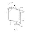
- FIG. 1 is a perspective view of a CMC component 10, such as but not limited to a turbine blade 20 or turbine vane.
- Turbine blade 20 is preferably formed of a ceramic matrix composite (CMC) material.
- Material for CMC component 10 includes, but is not limited to, an oxide based CMCs such as, but not limited to alumina, mullite, boron nitride, boron carbide, sialons (silicon, aluminum, oxygen, and nitrogen), intermetallics, and combinations thereof.
- a suitable example of material for CMC component 10 is, but not limited to, AN-720 (oxide-oxide based), which is available from COI Ceramics, Inc., San Diego, California, or a hybrid oxide CMC material.
- Turbine blade 20 includes an airfoil 22 against which the flow of hot exhaust gas is directed.
- Turbine blade 20 is mounted to a turbine disk (not shown) by a dovetail 24 which extends downwardly from airfoil 22 and engages a slot on the turbine disk.
- a platform 26 extends laterally outwardly from the area where airfoil 22 is joined to dovetail 24.
- Turbine blade 20 includes at least one cavity 120 as shown in FIG. 2 , extending along the interior of airfoil 22. During operation of power generation system, a flow of cooling air is directed through cavity 120 to reduce the temperature of airfoil 22.
- CMC turbine blade 20 is constructed using a lay-up technique and a near-net shape pre-form CMC cavity 100 (see FIGS. 2-5 ).
- Turbine blade 20 also includes blade tip 30.
- pre-form CMC cavity 100 includes a cavity 120 and a tip member 130 inserted into blade tip 30.
- Tip member 130 is formed from a plurality of plies 132 constructed separately in a tool or mold.
- Plies 132 are selected from ceramic plies that can include reinforcing material or are pre-impregnated with a matrix (see FIG. 3 ).
- An example of material for plies 132 includes, but is not limited to carbon, binder material and coated SiC fibers. As shown in FIG.
- mandrel 110 is used to form pre-form CMC cavity 100.
- at least one base ply 112 is applied to mandrel 110.
- more than one base plies 112 are applied to the mandrel.
- An example of suitable material for base ply 112 includes but is not limited to, plies containing carbon, SiC and binders.
- at least one ceramic matrix composite (CMC) ply 114 is applied to the at least one base ply 112.
- material for CMC 114 includes but is not limited to carbon, binder materials and coated SiC fiber.
- Mandrel 110 material is any material that can be removed from the densified structure by melting or chemical removal methods. Suitable examples of mandrel material include, but are not limited to, polymers, or other meltable or leachable materials.
- At least one base ply 112 and at least one CMC ply 114 are densified. Densification includes, but is not limited to melt infiltration, chemical vapor deposition, or other suitable densification methods. After densification, densified base ply 112 and at least one CMC ply 114 form pre-form CMC cavity 100 having a desired geometry and a cavity 120 formed therein, as shown in FIG. 4 .
- base ply 112 is applied to mandrel 110 but adjacent to tip member 130.
- at least one ceramic matrix composite (CMC) ply 114 is applied to the at least one base ply 112 on mandrel 110 and tip member 130, as shown in FIG. 3 .
- CMC ceramic matrix composite
- the assembly is autoclave processed and then mandrel 110 is removed, by methods, such as, but not limited to, melt-out or leaching processes depending on the mandrel composition.
- at least one base ply 112, at least one CMC ply 114, and tip member 130 are densified.
- Densification includes, but is not limited to, melt infiltration, chemical vapor deposition, or other suitable densification methods.
- Densified base ply 112, at least one CMC ply 114, and tip member 130 form pre-form CMC cavity 100 having a desired geometry and a cavity 120 formed therein, as shown in FIGS. 3-4 .
- mandrel 110 is removed and cavity 120 is formed by mandrel geometry 111 that remains after melt-out of mandrel 110.
- a portion 134 of tip member 130 is removed by machining to create location feature 136 for lay-up tool 200 (see FIG. 6 ). In another embodiment, no machining is necessary to create location feature 136 for lay-up tool 200.
- lay-up tool 200 can be used for fabricating or pre-forming CMC component 10 including pressure side 12 and suction side 14, dovetail 24, and platform 26.
- lay-up tool 200 includes a first set of opposing sides 202, 204 configured to abut each other and be fastened together.
- sides 202, 204 can be arranged as a mold for CMC component 10.
- Sides 202, 204 can include a first lay-up surface 206 designed to permit fabrication of the desired shape for CMC component 10.
- Tool 200 further includes a second set of opposing sides 208 configured to provide pressure on airfoil and dovetail 24, respectively (or, in the alternate embodiments, on the blade surrogate).
- Tool 200 may include a dovetail die 212 and/or a bridge 214 or other structures to provide a selectively configurable surface for laying up preform material, such base ply 112 and CMC plies 114.
- the dovetail die 212 may further define a lay-up surface, for example the first lay-up surface.
- the dovetail die 212 is configured for the airfoil and dovetail preform and the integral platform preform to be co-densified.
- a first baseply 600 is applied to first surface 206 of lay-up tool 200.
- first set of CMC plies 602 are applied adjacent to first baseply 600.
- pre-form CMC cavity 100 is applied adjacent to first set of CMC plies 602.
- a second set of CMC plies 604 is applied adjacent to pre-form CMC cavity 100.
- a second baseply 606 is applied adjacent to second set of CMC plies 604 and adjacent to second surface 207 of lay-up tool 200.
- first baseply 600, first set of CMC plies 602, pre-form CMC cavity 100, second set of CMC plies 604, and second baseply 606 an autoclave cycle is completed.
- the lay-up tool including first baseply 600, first set of CMC plies 602, pre-form CMC cavity 100, second set of CMC plies 604, and second baseply 606 is subject to typical autoclave pressures and temperature cycles used in the industry for composite materials. Autoclaving pulls out any volatiles in remaining in the plies and autoclave conditions can be varied depending on the ply material. After autoclaving a pre-form component having the desired geometry is available.
- the preform component is removed from the tooling and undergoes a burn-out process to remove any remaining mandrel material or additional binders in the pre-form component.
- the burn-out process is generally conducted at a temperature of approximately 426-648°C (approximately 800-1200°F).
- the pre-form component is placed in a vacuum furnace for densification. Densification can be conducted in a vacuum furnace having an established atmosphere at temperature above 1200°C to allow silicon or other materials to melt-infiltrate into the pre-form component.
- the pre-form component having a geometry like that of the component 10 and including first baseply 600, first set of CMC plies 602, pre-form CMC cavity 100, second set of CMC plies 604, and second baseply 606 is melt-infiltrated with Silicon or other materials to provide rigidity to CMC component 10.
- Method 900 includes providing lay-up tool, step 901.
- Method 900 includes providing mandrel 110 (see FIG. 3 ), step 903.
- Method include applying base ply 112 to mandrel 110 and optionally applying base ply 112 to tip member 130 (if present) (see FIG. 3 ), step 905.
- Method 900 includes laying-up at least one CMC ply 114 adjacent to base ply 112 on mandrel 110 in a lay-up tool(see FIG. 3 ), step 907.
- Method 900 includes removing mandrel 110 ( see Fig. 4 ), step 909.
- Method 900 includes removing mandrel 110 using any suitable method, such as but not limited to melting or leaching. After the step of densifying, step 911, a pre-from CMC cavity 100 remains having cavity 120 conforming to mandrel geometry 111, as shown in FIG. 4 .
- Method 1000 includes providing lay-up tool 200 (see FIG. 6 ), step 1001.
- Method 1000 includes applying first baseply 600 to first surface 206 of lay-up tool 200 (see FIG. 7 ), step 1003.
- Method 1000 includes laying up first set of CMC plies 602 adjacent to first baseply 600 on first surface 206 of lay-up tool (see FIG. 7 ), step 1005.
- Method 1000 includes providing pre-form CMC cavity 100 (see FIG. 5 ), step 1007.
- Pre-form CMC cavity 100 includes cavity 120 conforming to mandrel geometry 111, densified base ply 112 defining cavity 120 and at least one densified lay-up ply applied to densified base ply 112 (see FIG. 4 ).
- Method 1000 includes placing pre-form CMC cavity 100 adjacent to first set of CMC plies 602 in lay-up tool 200 (see FIG. 7 ), step 1009.
- Method 1000 includes laying-up a second set of CMC plies 604 adjacent to pre-form CMC cavity 100 in lay-up tool 200 (see FIG. 7 ), step 1011.
- Method 1000 includes applying second baseply 606 to second set of CMC plies 604, second baseply 606 being adjacent to second surface 207 of lay-up tool 200 (see FIG.
- Method 1000 includes densifying first baseply 600, first set of CMC plies 602, pre-from CMC cavity 100, second set of CMC plies 604, and second baseply 606 (see FIG. 7 ), to form CMC component 10, step 1015.
- step 1015 Prior to the step of densifying, step 1015, all of the items are situated in lay-up tool 200, first baseply 600, first set of CMC plies 602, pre-form CMC cavity 100, second set of CMC plies 604, and second baseply 606 are autoclaved. After autoclaving a pre-form component having the desired geometry is removed from the lay-up tool 200 and undergoes a burn-out cycle.
- CMC component 10 After burn-out, the pre-form component is placed in a vacuum furnace for densification. After densification formed CMC component 10 (see FIG. 1 ), includes a cavity 120 formed therein (see FIG. 8 ). After formation, component 10 can be machined to remove additional material from tip member 130 to form tip cap 138 (see FIG. 8 ).
Landscapes
- Engineering & Computer Science (AREA)
- Chemical & Material Sciences (AREA)
- Materials Engineering (AREA)
- Ceramic Engineering (AREA)
- Mechanical Engineering (AREA)
- General Engineering & Computer Science (AREA)
- Manufacturing & Machinery (AREA)
- Composite Materials (AREA)
- Structural Engineering (AREA)
- Organic Chemistry (AREA)
- Chemical Kinetics & Catalysis (AREA)
- Turbine Rotor Nozzle Sealing (AREA)
- Producing Shaped Articles From Materials (AREA)
- Press-Shaping Or Shaping Using Conveyers (AREA)
- Devices For Post-Treatments, Processing, Supply, Discharge, And Other Processes (AREA)
Abstract
Description
- The present invention relates generally to gas turbines for power generation and more specifically to methods of forming ceramic matrix composite components for gas turbines.
- Silicon carbide (SiC)-based ceramic matrix composite (CMC) materials have been proposed as materials for certain components of gas turbine engines, such as the turbine blades, vanes, nozzles, and buckets. Various methods are known for fabricating SiC-based CMC components, including Silicomp, melt infiltration (MI), chemical vapor infiltration (CVI), polymer inflation pyrolysis (PIP), and oxide/oxide processes. Though these fabrication techniques significantly differ from each other, each involves the use of hand lay-up and tooling or dies to produce a near-net-shape part through a process that includes the application of heat at various processing stages.
- As with turbine blades and vanes formed from more conventional superalloy materials, CMC blades and vanes are primarily equipped with cavities and cooling passages to reduce weight, reduce centrifugal load, and reduce operating temperatures of the components. These features are typically formed in CMC components using a combination of removable and expendable tooling.
- Forming CMC component with a cavity includes a number of steps, including using pre-forms. First, a plurality of ceramic plies, some of which can include reinforcing material or are pre-impregnated with matrix, are laid up on a mandrel or mold in a pre-determined pattern to provide desired final or near-net-shape and desired mechanical properties of component. The mandrel is generally selected from various polymers, or other meltable materials. The laid-up plies may be pre-impregnated (pre-preg) with matrix material, such as SiC or impregnated with matrix after lay-up of the plies. Prior to rigidization of the CMC pre-form, the mandrel is removed through a burn-out cycle. In the burn-out cycle, the mandrel forming materials, such as, various polymers, or other meltable materials are melted out.
- After the burn-out cycle, the CMC pre-form component is very fragile due to burn-off of the volatile substances of the composite. In certain cases, one end of the CMC preform requires capping or closing before use in gas turbines in order to close off the hollow region for use in the turbine. In known processes, to close the open end area of the CMC pre-form a cap or plug is inserted after the burnout cycle when the CMC pre-forms are in their most fragile state. The plug can be formed from of a CMC laminate part having a number of plies, and shaped so as to fill the open end of the CMC pre-form. Use of a separate forming, cutting and layup process is time and labor intensive simply to create a closed structure. Challenges also arise with placing the pre-rigidized CMC laminate having a number of plies into the open end. For example, because both the CMC laminate and pre-form are fragile prior to densification, these components can be easily damaged during assembly.
- Therefore, a method of forming pre-form ceramic matrix composite cavity, a pre-form ceramic matrix composite cavity, and a method of forming ceramic matrix composite components that do not suffer from the above drawbacks is desirable in the art.
- Certain embodiments commensurate in scope with the originally claimed invention are summarized below. These embodiments are not intended to limit the scope of the claimed invention, but rather these embodiments are intended only to provide a brief summary of possible forms of the invention. Indeed, the invention may encompass a variety of forms that may be similar to or different from the embodiments set forth below.
- According to one aspect, the present invention resides in a method of forming pre-form ceramic matrix composite cavity for a ceramic matrix component. The method includes providing a mandrel and applying a base ply to the mandrel. The method includes laying-up at least one CMC ply on the base ply, removing the mandrel and densifying the base ply and the at least one CMC ply. The remaining densified base ply and at least one CMC ply form a ceramic matrix component having a desired geometry and a cavity formed therein.
- According to another aspect, the present invention resides in a pre-form ceramic matrix composite cavity for a ceramic matrix composite component. The pre-form ceramic matrix composite cavity includes a cavity conforming to a mandrel geometry. The pre-form ceramic matrix composite cavity includes a densified base ply defining the cavity. The pre-form ceramic matrix composite cavity includes at least one densified lay-up ply applied to the densified base ply. The pre-form ceramic matrix composite having a desired geometry and the cavity formed therein.
- According to yet another aspect, the present invention resides in a method of forming a ceramic matrix composite component. The method includes providing a lay-up tool having a first surface and a second surface. The method includes applying a first base ply to the first surface of the lay-up tool. The method includes laying-up a first set of CMC plies adjacent to the first base ply. The method includes providing a pre-form ceramic matrix composite cavity. The pre-form ceramic matrix composite includes a cavity conforming to a mandrel geometry, a densified base ply defining the cavity, and at least one densified lay-up ply applied to the densified base ply, the pre-form ceramic matrix composite cavity having a desired geometry and the cavity formed therein. The method includes placing the pre-form ceramic matrix composite cavity adjacent to the first set of CMC plies in the lay-up tool. The method includes laying-up a second set of CMC plies adjacent to the pre-form ceramic matrix composite cavity. The method includes applying a second base ply to the second set of CMC plies, the second base ply adjacent to the second surface of the lay-up tool. The method includes densifying the first base ply, the first set of CMC plies, the pre-form matrix ceramic composite cavity, the second set of CMC plies, and the second base ply. The ceramic matrix composite is formed having a desired geometry and the cavity formed therein.
- Other features and advantages of the present invention will be apparent from the following more detailed description of the preferred embodiment, taken in conjunction with the accompanying drawings which illustrate, by way of example, the principles of the invention.
- Embodiments of the present invention will now be described, by way of example only, with reference to the accompanying drawings in which:
-
FIG. 1 is a perspective view of a ceramic matrix composite (CMC) component of the present disclosure. -
FIG. 2 is a perspective view of pre-form CMC cavity of the present disclosure. -
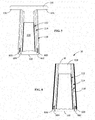
FIG. 3 is a sectional view taken in direction 3-3 ofFIG. 2 of the pre-form CMC cavity of the present disclosure. -
FIG. 4 is a schematic view ofFIG. 3 after a mandrel is removed and depicting the preform CMC cavity of the present disclosure. -
FIG. 5 is a schematic view ofFIG. 4 including air foil shell plies of the present disclosure. -
FIG. 6 is a perspective view of the lay-up tool of the present disclosure. -
FIG. 7 is schematic view of the layers for the CMC component in the lay-up tool of the present disclosure. -
FIG. 8 is sectional schematic view of CMC component of the present disclosure. -
FIG. 9 is a flow chart of the method of making the pre-from ceramic matrix composite of the present disclosure. -
FIG. 10 is a flow chart of the method of making a CMC component of the present disclosure. - Wherever possible, the same reference numbers will be used throughout the drawings to represent the same parts.
- Provided is an economically viable method of forming a ceramic matrix composite (CMC) component, specifically a method of forming a CMC blade or vane, in such a manner that, the CMC components do not suffer from the processing and performance drawbacks in the prior art. One advantage of an embodiment of the present disclosure includes an opening in the bottom cavity to allow for melt-out of the mandrel material and cleaning of the cavity. Yet another advantage is a tip cap and cavity combination that is highly durable because it has undergone densification. Another advantage of an embodiment of the present disclosure includes a reduced ply volume of the blade shell at the time of melt-out of the mandrel material which allows for better control of the melt-out of the mandrel material. Yet another advantage of the present embodiment is that a formed pre-form CMC cavity for forming a CMC component allows for cavity inspections prior to lay-up of the air foil plies, which prevents the loss of the whole component if cavity defects are found. Another advantage is that the tip cap portion of the pre-form ceramic matrix composite cavity can be used for location of the pre-form ceramic matrix composite cavity in the lay-up tool. Yet another advantage is that the method allows for better process control during the autoclave cycle in lay-up tool which enables better dimensional control. Another advantage is that the method allows for using tailored polymers or other mandrel materials for the mandrel that will melt-out or leach out during subsequent processing.
- One or more specific embodiments of the present invention will be described below. In an effort to provide a concise description of these embodiments, all features of an actual implementation may not be described in the specification. It should be appreciated that in the development of any such actual implementation, as in any engineering or design project, numerous implementation-specific decisions must be made to achieve the developers' specific goals, such as compliance with system-related and business-related constraints, which may vary from one implementation to another. Moreover, it should be appreciated that such a development effort might be complex and time consuming, but would nevertheless be a routine undertaking of design, fabrication, and manufacture for those of ordinary skill having the benefit of this disclosure.
- When introducing elements of various embodiments of the present invention, the articles "a," "an," "the," and "said" are intended to mean that there are one or more of the elements. The terms "comprising," "including," and "having" are intended to be inclusive and mean that there may be additional elements other than the listed elements.
- Systems used to generate power include, but are not limited to, gas turbines, steam turbines, and other turbine assemblies such as land based aero-derivatives used for power generation. In certain applications, the power generation systems, including the turbomachinery therein (e.g., turbines, compressors, and pumps) and other machinery may include components that are exposed to heavy wear conditions. For example, certain power generation system components, such as blades, buckets, casings, rotor wheels, shafts, shrouds, nozzles, and so forth, may operate in high heat and high revolution environments. These components are manufactured using ceramic matrix composites and these components may also include cooling passages. The present disclosure provides method to form ceramic matrix composite (CMC) components including cooling passages. An exemplary embodiment of the disclosure is shown in
FIGS. 1-8 as a turbine blade, but the present disclosure is not limited to the illustrated structure. -
FIG. 1 is a perspective view of aCMC component 10, such as but not limited to aturbine blade 20 or turbine vane.Turbine blade 20 is preferably formed of a ceramic matrix composite (CMC) material. Material forCMC component 10 includes, but is not limited to, an oxide based CMCs such as, but not limited to alumina, mullite, boron nitride, boron carbide, sialons (silicon, aluminum, oxygen, and nitrogen), intermetallics, and combinations thereof. A suitable example of material forCMC component 10 is, but not limited to, AN-720 (oxide-oxide based), which is available from COI Ceramics, Inc., San Diego, California, or a hybrid oxide CMC material. Suitable examples of materials used to makeCMC components 10, include but are not limited to, SiC fibers impregnated with a SiC and carbon matrix with various binders.Turbine blade 20 includes anairfoil 22 against which the flow of hot exhaust gas is directed.Turbine blade 20 is mounted to a turbine disk (not shown) by adovetail 24 which extends downwardly fromairfoil 22 and engages a slot on the turbine disk. Aplatform 26 extends laterally outwardly from the area whereairfoil 22 is joined to dovetail 24.Turbine blade 20 includes at least onecavity 120 as shown inFIG. 2 , extending along the interior ofairfoil 22. During operation of power generation system, a flow of cooling air is directed throughcavity 120 to reduce the temperature ofairfoil 22. -
CMC turbine blade 20, as shown inFIG. 1 , is constructed using a lay-up technique and a near-net shape pre-form CMC cavity 100 (seeFIGS. 2-5 ).Turbine blade 20 also includesblade tip 30. As shown inFIG. 2 ,pre-form CMC cavity 100 includes acavity 120 and atip member 130 inserted intoblade tip 30.Tip member 130 is formed from a plurality ofplies 132 constructed separately in a tool or mold.Plies 132 are selected from ceramic plies that can include reinforcing material or are pre-impregnated with a matrix (seeFIG. 3 ). An example of material forplies 132 includes, but is not limited to carbon, binder material and coated SiC fibers. As shown inFIG. 3 ,mandrel 110 is used to formpre-form CMC cavity 100. In formingpre-form CMC cavity 100, at least onebase ply 112 is applied tomandrel 110. In an alternative embodiment, more than one base plies 112 are applied to the mandrel. An example of suitable material forbase ply 112, includes but is not limited to, plies containing carbon, SiC and binders. Next, at least one ceramic matrix composite (CMC) ply 114 is applied to the at least onebase ply 112. An example of material forCMC 114 includes but is not limited to carbon, binder materials and coated SiC fiber. After at least onebase ply 112 and at least one CMC ply 114 are assembled in desired geometry or shape onmandrel 110, themandrel 110 is removed.Mandrel 110 material is any material that can be removed from the densified structure by melting or chemical removal methods. Suitable examples of mandrel material include, but are not limited to, polymers, or other meltable or leachable materials. After themandrel 110 is removed, at least onebase ply 112 and at least one CMC ply 114 are densified. Densification includes, but is not limited to melt infiltration, chemical vapor deposition, or other suitable densification methods. After densification, densifiedbase ply 112 and at least one CMC ply 114 formpre-form CMC cavity 100 having a desired geometry and acavity 120 formed therein, as shown inFIG. 4 . - In one embodiment, base ply 112 is applied to
mandrel 110 but adjacent to tipmember 130. Next, at least one ceramic matrix composite (CMC) ply 114 is applied to the at least one base ply 112 onmandrel 110 andtip member 130, as shown inFIG. 3 . After at least onebase ply 112 and at least one CMC ply 114 are assembled in desired geometry or shape onmandrel 110, the assembly is autoclave processed and then mandrel 110 is removed, by methods, such as, but not limited to, melt-out or leaching processes depending on the mandrel composition. After removal ofmandrel 110, at least onebase ply 112, at least one CMC ply 114, andtip member 130 are densified. Densification includes, but is not limited to, melt infiltration, chemical vapor deposition, or other suitable densification methods.Densified base ply 112, at least one CMC ply 114, andtip member 130 formpre-form CMC cavity 100 having a desired geometry and acavity 120 formed therein, as shown inFIGS. 3-4 . - As shown in
FIG. 4 ,mandrel 110 is removed andcavity 120 is formed bymandrel geometry 111 that remains after melt-out ofmandrel 110. Also as shown inFIG. 4 , in one embodiment, aportion 134 oftip member 130 is removed by machining to createlocation feature 136 for lay-up tool 200 (seeFIG. 6 ). In another embodiment, no machining is necessary to createlocation feature 136 for lay-uptool 200. - As shown in
FIGS. 5-7 ,pre-form CMC cavity 100 is used in lay-up tool 200 (seeFIG. 6 ) to form CMC component 10 (seeFIG. 8 ). As shown inFIG. 6 , lay-uptool 200 can be used for fabricating orpre-forming CMC component 10 includingpressure side 12 andsuction side 14,dovetail 24, andplatform 26. Generally, lay-uptool 200 includes a first set of opposingsides FIG. 6 ,sides CMC component 10.Sides surface 206 designed to permit fabrication of the desired shape forCMC component 10.Tool 200 further includes a second set of opposingsides 208 configured to provide pressure on airfoil anddovetail 24, respectively (or, in the alternate embodiments, on the blade surrogate).Tool 200 may include a dovetail die 212 and/or abridge 214 or other structures to provide a selectively configurable surface for laying up preform material,such base ply 112 and CMC plies 114. In one embodiment, the dovetail die 212 may further define a lay-up surface, for example the first lay-up surface. In another embodiment, the dovetail die 212 is configured for the airfoil and dovetail preform and the integral platform preform to be co-densified. - As shown in
FIG. 7 , in formingcomponent 10, afirst baseply 600 is applied tofirst surface 206 of lay-uptool 200. Next, first set of CMC plies 602 are applied adjacent tofirst baseply 600. Next,pre-form CMC cavity 100 is applied adjacent to first set of CMC plies 602. Next, a second set of CMC plies 604 is applied adjacent topre-form CMC cavity 100. Asecond baseply 606 is applied adjacent to second set of CMC plies 604 and adjacent tosecond surface 207 of lay-uptool 200. After all of the items are situated in lay-uptool 200,first baseply 600, first set of CMC plies 602,pre-form CMC cavity 100, second set of CMC plies 604, and second baseply 606 an autoclave cycle is completed. The lay-up tool includingfirst baseply 600, first set of CMC plies 602,pre-form CMC cavity 100, second set of CMC plies 604, andsecond baseply 606 is subject to typical autoclave pressures and temperature cycles used in the industry for composite materials. Autoclaving pulls out any volatiles in remaining in the plies and autoclave conditions can be varied depending on the ply material. After autoclaving a pre-form component having the desired geometry is available. The preform component is removed from the tooling and undergoes a burn-out process to remove any remaining mandrel material or additional binders in the pre-form component. The burn-out process is generally conducted at a temperature of approximately 426-648°C (approximately 800-1200°F). After burn-out, the pre-form component is placed in a vacuum furnace for densification. Densification can be conducted in a vacuum furnace having an established atmosphere at temperature above 1200°C to allow silicon or other materials to melt-infiltrate into the pre-form component. During densification the pre-form component, having a geometry like that of thecomponent 10 and includingfirst baseply 600, first set of CMC plies 602,pre-form CMC cavity 100, second set of CMC plies 604, andsecond baseply 606 is melt-infiltrated with Silicon or other materials to provide rigidity toCMC component 10. - A
method 900 of forming apre-form CMC cavity 100 is shown inFIG. 9 .Method 900 includes providing lay-up tool,step 901.Method 900 includes providing mandrel 110 (seeFIG. 3 ),step 903. Method include applying base ply 112 tomandrel 110 and optionally applying base ply 112 to tip member 130 (if present) (seeFIG. 3 ),step 905.Method 900 includes laying-up at least one CMC ply 114 adjacent to base ply 112 onmandrel 110 in a lay-up tool(seeFIG. 3 ),step 907.Method 900 includes removing mandrel 110 (seeFig. 4 ),step 909. Aftermandrel 110 is removed,base ply 112, and at least one CMC ply 114, are densified,step 911.Method 900 includes removingmandrel 110 using any suitable method, such as but not limited to melting or leaching. After the step of densifying,step 911, apre-from CMC cavity 100 remains havingcavity 120 conforming tomandrel geometry 111, as shown inFIG. 4 . - A
method 1000 of forming aCMC component 10 is shown inFIG. 10 .Method 1000 includes providing lay-up tool 200 (seeFIG. 6 ),step 1001.Method 1000 includes applyingfirst baseply 600 tofirst surface 206 of lay-up tool 200 (seeFIG. 7 ),step 1003.Method 1000 includes laying up first set of CMC plies 602 adjacent tofirst baseply 600 onfirst surface 206 of lay-up tool (seeFIG. 7 ),step 1005.Method 1000 includes providing pre-form CMC cavity 100 (seeFIG. 5 ),step 1007.Pre-form CMC cavity 100 includescavity 120 conforming tomandrel geometry 111, densified base ply 112defining cavity 120 and at least one densified lay-up ply applied to densified base ply 112 (seeFIG. 4 ).Method 1000 includes placingpre-form CMC cavity 100 adjacent to first set of CMC plies 602 in lay-up tool 200 (seeFIG. 7 ),step 1009.Method 1000 includes laying-up a second set of CMC plies 604 adjacent topre-form CMC cavity 100 in lay-up tool 200 (seeFIG. 7 ),step 1011.Method 1000 includes applyingsecond baseply 606 to second set of CMC plies 604,second baseply 606 being adjacent tosecond surface 207 of lay-up tool 200 (seeFIG. 7 ),step 1013.Method 1000 includes densifyingfirst baseply 600, first set of CMC plies 602,pre-from CMC cavity 100, second set of CMC plies 604, and second baseply 606 (seeFIG. 7 ), to formCMC component 10,step 1015. Prior to the step of densifying,step 1015, all of the items are situated in lay-uptool 200,first baseply 600, first set of CMC plies 602,pre-form CMC cavity 100, second set of CMC plies 604, andsecond baseply 606 are autoclaved. After autoclaving a pre-form component having the desired geometry is removed from the lay-uptool 200 and undergoes a burn-out cycle. After burn-out, the pre-form component is placed in a vacuum furnace for densification. After densification formed CMC component 10 (seeFIG. 1 ), includes acavity 120 formed therein (seeFIG. 8 ). After formation,component 10 can be machined to remove additional material fromtip member 130 to form tip cap 138 (seeFIG. 8 ). - While the invention has been described with reference to a preferred embodiment, it will be understood by those skilled in the art that various changes may be made and equivalents may be substituted for elements thereof without departing from the scope of the invention. In addition, many modifications may be made to adapt a particular situation or material to the teachings of the invention without departing from the essential scope thereof. Therefore, it is intended that the invention not be limited to the particular embodiment disclosed as the best mode contemplated for carrying out this invention, but that the invention will include all embodiments falling within the scope of the appended claims.
- Various aspects and embodiments of the present invention are defined by the following numbered clauses:
- 1. A method of forming a ceramic matrix composite component comprising:
- providing a lay-up tool having a first surface and a second surface;
- applying a first base ply to the first surface of the lay-up tool;
- laying-up a first set of CMC plies adjacent to the first base ply;
- providing a pre-form ceramic matrix composite cavity comprising:
- a cavity conforming to a mandrel geometry;
- a densified base ply defining the cavity; and
- at least one densified lay-up ply applied to the densified base ply, the pre-form ceramic matrix composite cavity having a desired geometry and the cavity formed therein;
- placing the pre-form ceramic matrix composite cavity adjacent to the first set of CMC plies in the lay-up tool;
- laying-up a second set of CMC plies adjacent to the pre-form ceramic matrix composite cavity;
- applying a second base ply to the second set of CMC plies, the second base ply adjacent to the second surface of the lay-up tool; and
- densifying the first base ply, the first set of CMC plies, the pre-form ceramic matrix composite cavity, the second set of CMC plies, and the second base ply;
- wherein the ceramic matrix composite is formed having a desired geometry and the cavity formed therein.
- 2. The method of clause 1, wherein the ceramic matrix composite cavity includes a tip member.
- 3. The method of clause 1 or 2, including an additional step of after the step of densifying of inserting a tip member into the pre-from ceramic matrix composite cavity.
- 4. The method of
clause 1, 2 or 3, including an additional step after the step of densifying of machining the ceramic matrix composite to a desired geometry. - 5. The method of any of clauses 1 to 4, wherein the step of densifying includes melt infiltration or chemical vapor deposition.
- 6. The method of any of clauses 1 to 5, including an additional step of after the step of applying the second base ply of autoclaving the first base ply, the first set of CMC plies, the pre-form ceramic matrix composite cavity, the second set of CMC plies, and the second base ply.
- 7. The method of clause 6, including an additional step of after the step of autoclaving of removing the tool.
- 8. The method of clause 7, including an additional step after the step of removing the tool of burn-out of the first base ply, the first set of CMC plies, the pre-form ceramic matrix composite cavity, the second set of CMC plies, and the second base ply.
Claims (16)
- A method of forming pre-form ceramic matrix composite cavity (100) for a ceramic matrix and a ceramic matrix composite component (10) comprising:providing a mandrel (110);applying a base ply (112) to the mandrel (110);laying-up at least one CMC ply (114) on the base ply (112);removing the mandrel (110);densifying the base ply (112) and the at least one CMC ply (114); andwherein the remaining densified base ply (112) and at least one CMC ply (114) form the pre-form ceramic matrix component cavity (110) having a desired geometry and a cavity (120) formed therein.
- The method of claim 1, including an additional step prior to the step of applying the base ply (112) to the mandrel (110) of aligning a tip member (130) adjacent to the mandrel (110).
- The method of claim 2, including an additional step after removing the mandrel (110) of machining the tip member (130) to remove additional material.
- The method of any of claims 1 to 3, including an additional step after removing the mandrel (110) of laying-up a first set of CMC plies (602) in a lay-up tool (200) and applying the pre-form ceramic matrix composite cavity (100) to the first set of CMC plies (602) in the lay-up tool (200).
- The method of claim 4, including an additional step after the step of applying the pre-form ceramic matrix composite cavity (200) of laying-up a second set of CMC plies (604) to the pre-form ceramic matrix composite cavity (100).
- The method of claim 5, including an additional step after laying-up the second set of CMC plies (604) of processing the first set of CMC plies (602), the pre-form ceramic matrix composite cavity (100), and the second set of CMC plies (604) in the lay-up tool (200) to form the ceramic matrix composite component (10).
- The method of claim 6, further comprising:applying a second base ply (604) to the second set of CMC plies, (604) the second base ply (606) adjacent to a second surface (207) of the lay-up tool (200); anddensifying the first base ply (600), the first set of CMC plies (602), the pre-form ceramic matrix composite cavity (100), the second set of CMC plies (604), and the second base ply (606).
- The method of claim 7, including an additional step of after the step of applying the second base ply (606) of autoclaving the first base ply (600), the first set of CMC plies (602), the pre-form ceramic matrix composite cavity (100), the second set of CMC plies (604), and the second base ply (606).
- The method of claim 8, including an additional step of after the step of autoclaving of removing the tool (200).
- The method of claim 9, including an additional step after the step of removing the tool (200) of burn-out of the first base ply (600), the first set of CMC plies (602), the pre-form ceramic matrix composite cavity (100), the second set of CMC plies (604), and the second base ply (606).
- The method of any preceding claim, wherein the step of densifying includes melt infiltration or chemical vapor deposition.
- The method of any preceding claim, wherein the step of removing the mandrel (110) includes heat or chemical removal methods.
- A pre-form ceramic matrix composite cavity (100) for a ceramic matrix composite component (10) comprising:a cavity (120) conforming to a mandrel geometry;a densified base ply (112) defining the cavity (100); andat least one densified lay-up ply (114) applied to the densified base ply (112), the pre-form ceramic matrix composite cavity (100) having a desired geometry and the cavity (120) formed therein.
- The pre-form ceramic matrix composite of claim 13, including a tip member (130) in the cavity (120).
- The pre-form ceramic matrix composite of claim 14, wherein the tip member (130) is pre-formed.
- The pre-from ceramic matrix composite of any of claims 13 to 15, wherein the ceramic matrix composite component (10) is a turbine blade, turbine nozzle, turbine bucket, and combinations thereof.
Applications Claiming Priority (1)
| Application Number | Priority Date | Filing Date | Title |
|---|---|---|---|
| US13/446,465 US9050769B2 (en) | 2012-04-13 | 2012-04-13 | Pre-form ceramic matrix composite cavity and method of forming and method of forming a ceramic matrix composite component |
Publications (3)
| Publication Number | Publication Date |
|---|---|
| EP2650478A2 true EP2650478A2 (en) | 2013-10-16 |
| EP2650478A3 EP2650478A3 (en) | 2017-10-11 |
| EP2650478B1 EP2650478B1 (en) | 2020-12-16 |
Family
ID=47666059
Family Applications (1)
| Application Number | Title | Priority Date | Filing Date |
|---|---|---|---|
| EP13154858.8A Active EP2650478B1 (en) | 2012-04-13 | 2013-02-11 | Ceramic matrix composite pre-form with a cavity and method of forming such a pre-form |
Country Status (4)
| Country | Link |
|---|---|
| US (2) | US9050769B2 (en) |
| EP (1) | EP2650478B1 (en) |
| JP (1) | JP6325192B2 (en) |
| RU (1) | RU2013105722A (en) |
Cited By (2)
| Publication number | Priority date | Publication date | Assignee | Title |
|---|---|---|---|---|
| US20160214283A1 (en) * | 2015-01-26 | 2016-07-28 | General Electric Company | Composite tool and method for forming composite components |
| EP2971549B1 (en) * | 2013-03-15 | 2020-02-12 | Rolls-Royce Corporation | Gas turbine engine blade, corresponding gas turbine engine and method of forming |
Families Citing this family (22)
| Publication number | Priority date | Publication date | Assignee | Title |
|---|---|---|---|---|
| US10011043B2 (en) * | 2012-04-27 | 2018-07-03 | General Electric Company | Method of producing an internal cavity in a ceramic matrix composite |
| US10450235B2 (en) | 2012-04-27 | 2019-10-22 | General Electric Company | Method of producing an internal cavity in a ceramic matrix composite and mandrel therefor |
| US9896945B2 (en) * | 2013-11-25 | 2018-02-20 | General Electric Company | Process of producing a ceramic matrix composite turbine bucket, insert for a ceramic matrix composite turbine bucket and ceramic matrix composite turbine bucket |
| CA2936186C (en) * | 2014-01-17 | 2023-02-28 | General Electric Company | Ceramic matrix composite turbine blade squealer tip with flare and method thereof |
| EP2902588B1 (en) * | 2014-01-31 | 2020-06-24 | Ansaldo Energia IP UK Limited | Composite turbine blade for high-temperature applications |
| US20160251272A1 (en) * | 2015-02-27 | 2016-09-01 | General Electric Company | Laminate structure fabricated using chemical vapor infiltration (cvi) |
| US9926796B2 (en) * | 2015-07-28 | 2018-03-27 | General Electric Company | Ply, method for manufacturing ply, and method for manufacturing article with ply |
| US10018054B2 (en) * | 2015-10-23 | 2018-07-10 | General Electric Company | Fabrication of gas turbine engine components using multiple processing steps |
| US10273813B2 (en) * | 2015-10-29 | 2019-04-30 | General Electric Company | Ceramic matrix composite component and process of producing a ceramic matrix composite component |
| US10207471B2 (en) * | 2016-05-04 | 2019-02-19 | General Electric Company | Perforated ceramic matrix composite ply, ceramic matrix composite article, and method for forming ceramic matrix composite article |
| US10605095B2 (en) * | 2016-05-11 | 2020-03-31 | General Electric Company | Ceramic matrix composite airfoil cooling |
| US10329927B2 (en) * | 2016-08-15 | 2019-06-25 | General Electric Company | Hollow ceramic matrix composite article, mandrel for forming hollow ceramic matrix composite article, and method for forming hollow ceramic matrix composite article |
| US10391724B2 (en) * | 2017-02-15 | 2019-08-27 | General Electric Company | Method of forming pre-form ceramic matrix composite mold and method of forming a ceramic matrix composite component |
| US10569481B2 (en) * | 2017-06-26 | 2020-02-25 | General Electric Company | Shaped composite ply layups and methods for shaping composite ply layups |
| US10801108B2 (en) * | 2017-08-28 | 2020-10-13 | Raytheon Technologies Corporation | Method for fabricating ceramic matrix composite components |
| US10329201B2 (en) * | 2017-09-21 | 2019-06-25 | General Electric Company | Ceramic matrix composite articles formation method |
| FR3071830B1 (en) | 2017-10-02 | 2021-03-12 | Safran Ceram | PROCESS FOR MAKING A HOLLOW PART IN COMPOSITE MATERIAL WITH CERAMIC MATRIX |
| US11174203B2 (en) | 2018-10-25 | 2021-11-16 | General Electric Company | Ceramic matrix composite turbine nozzle shell and method of assembly |
| US11035239B2 (en) | 2018-10-25 | 2021-06-15 | General Electric Company | Ceramic matrix composite turbine nozzle shell and method of assembly |
| US11149561B2 (en) | 2019-08-12 | 2021-10-19 | Rolls-Royce Plc | System and method for making ceramic matrix composite vane with profiled end walls |
| CN112123515B (en) * | 2020-09-07 | 2022-04-19 | 中国航发北京航空材料研究院 | A kind of ceramic matrix composite material open shell integral molding method and mold |
| US12601267B2 (en) * | 2024-02-15 | 2026-04-14 | Rtx Corporation | Forming gas turbine engine airfoils from CMCs with a kickback to facilitate mandrel removal |
Family Cites Families (24)
| Publication number | Priority date | Publication date | Assignee | Title |
|---|---|---|---|---|
| US5710414A (en) | 1991-04-05 | 1998-01-20 | The Boeing Company | Internal tooling for induction heating |
| US6431255B1 (en) * | 1998-07-21 | 2002-08-13 | General Electric Company | Ceramic shell mold provided with reinforcement, and related processes |
| US6056915A (en) | 1998-10-21 | 2000-05-02 | Alliedsignal Inc. | Rapid manufacture of metal and ceramic tooling |
| GB9827889D0 (en) * | 1998-12-18 | 2000-03-29 | Rolls Royce Plc | A method of manufacturing a ceramic matrix composite |
| US6274078B1 (en) | 1999-01-27 | 2001-08-14 | General Electric Company | Method of removing cores from ceramic matrix composite articles |
| US7093359B2 (en) * | 2002-09-17 | 2006-08-22 | Siemens Westinghouse Power Corporation | Composite structure formed by CMC-on-insulation process |
| US7255535B2 (en) * | 2004-12-02 | 2007-08-14 | Albrecht Harry A | Cooling systems for stacked laminate CMC vane |
| US7153096B2 (en) * | 2004-12-02 | 2006-12-26 | Siemens Power Generation, Inc. | Stacked laminate CMC turbine vane |
| US7556477B2 (en) * | 2005-10-04 | 2009-07-07 | General Electric Company | Bi-layer tip cap |
| US7600979B2 (en) * | 2006-11-28 | 2009-10-13 | General Electric Company | CMC articles having small complex features |
| US20080149255A1 (en) * | 2006-12-20 | 2008-06-26 | General Electric Company | Ceramic composite article manufacture using thin plies |
| FR2913053B1 (en) | 2007-02-23 | 2009-05-22 | Snecma Sa | PROCESS FOR MANUFACTURING A GAS TURBINE CASE OF COMPOSITE MATERIAL AND CARTER THUS OBTAINED |
| DE102007015909A1 (en) * | 2007-04-02 | 2008-10-09 | Mt Aerospace Ag | Process for producing fiber-reinforced hollow bodies |
| US8357323B2 (en) * | 2008-07-16 | 2013-01-22 | Siemens Energy, Inc. | Ceramic matrix composite wall with post laminate stitching |
| FR2934014B1 (en) * | 2008-07-17 | 2011-05-13 | Snecma Propulsion Solide | PROCESS FOR PRODUCING A PIPE OR DIVERGENT OF TUBE IN COMPOSITE MATERIAL |
| US8714932B2 (en) | 2008-12-31 | 2014-05-06 | General Electric Company | Ceramic matrix composite blade having integral platform structures and methods of fabrication |
| GB0901189D0 (en) * | 2009-01-26 | 2009-03-11 | Rolls Royce Plc | Manufacturing a composite component |
| JP5472314B2 (en) * | 2009-11-13 | 2014-04-16 | 株式会社Ihi | Wing production method |
| GB201006625D0 (en) * | 2010-04-21 | 2010-06-02 | Rolls Royce Plc | A method of manufacturing a ceramic matrix composite article |
| US8834125B2 (en) * | 2011-05-26 | 2014-09-16 | United Technologies Corporation | Hybrid rotor disk assembly with a ceramic matrix composite airfoil for a gas turbine engine |
| US8734107B2 (en) * | 2011-05-31 | 2014-05-27 | General Electric Company | Ceramic-based tip cap for a turbine bucket |
| US9663404B2 (en) * | 2012-01-03 | 2017-05-30 | General Electric Company | Method of forming a ceramic matrix composite and a ceramic matrix component |
| US9410437B2 (en) * | 2012-08-14 | 2016-08-09 | General Electric Company | Airfoil components containing ceramic-based materials and processes therefor |
| US20140199174A1 (en) * | 2013-01-11 | 2014-07-17 | General Electric Company | Method of forming a ceramic matrix composite component, a ceramic matrix composite component and a tip member |
-
2012
- 2012-04-13 US US13/446,465 patent/US9050769B2/en active Active
-
2013
- 2013-01-31 JP JP2013016278A patent/JP6325192B2/en active Active
- 2013-02-11 EP EP13154858.8A patent/EP2650478B1/en active Active
- 2013-02-12 RU RU2013105722/03A patent/RU2013105722A/en not_active Application Discontinuation
-
2015
- 2015-06-09 US US14/734,028 patent/US9981438B2/en active Active
Non-Patent Citations (1)
| Title |
|---|
| None |
Cited By (3)
| Publication number | Priority date | Publication date | Assignee | Title |
|---|---|---|---|---|
| EP2971549B1 (en) * | 2013-03-15 | 2020-02-12 | Rolls-Royce Corporation | Gas turbine engine blade, corresponding gas turbine engine and method of forming |
| US20160214283A1 (en) * | 2015-01-26 | 2016-07-28 | General Electric Company | Composite tool and method for forming composite components |
| CN105818253A (en) * | 2015-01-26 | 2016-08-03 | 通用电气公司 | Composite tool and method for forming composite components |
Also Published As
| Publication number | Publication date |
|---|---|
| US20140193577A1 (en) | 2014-07-10 |
| RU2013105722A (en) | 2014-08-20 |
| EP2650478A3 (en) | 2017-10-11 |
| EP2650478B1 (en) | 2020-12-16 |
| JP6325192B2 (en) | 2018-05-16 |
| US20180099467A1 (en) | 2018-04-12 |
| US9050769B2 (en) | 2015-06-09 |
| US9981438B2 (en) | 2018-05-29 |
| JP2014001723A (en) | 2014-01-09 |
Similar Documents
| Publication | Publication Date | Title |
|---|---|---|
| EP2650478B1 (en) | Ceramic matrix composite pre-form with a cavity and method of forming such a pre-form | |
| JP6888933B2 (en) | Ceramic Matrix Composite Components and Methods for Manufacturing Ceramic Matrix Composite Components | |
| EP3162559B1 (en) | Process of producing a ceramic matrix composite component | |
| US10260358B2 (en) | Ceramic matrix composite component and process of producing a ceramic matrix composite component | |
| EP2617695B1 (en) | Method of forming a ceramic matrix composite and a ceramic matrix composite component | |
| US8980435B2 (en) | CMC component, power generation system and method of forming a CMC component | |
| CA3102096C (en) | Ceramic matrix composite component and method of producing a ceramic matrix composite component | |
| US20160214283A1 (en) | Composite tool and method for forming composite components | |
| US20140199174A1 (en) | Method of forming a ceramic matrix composite component, a ceramic matrix composite component and a tip member | |
| JP2017105698A5 (en) |
Legal Events
| Date | Code | Title | Description |
|---|---|---|---|
| PUAI | Public reference made under article 153(3) epc to a published international application that has entered the european phase |
Free format text: ORIGINAL CODE: 0009012 |
|
| AK | Designated contracting states |
Kind code of ref document: A2 Designated state(s): AL AT BE BG CH CY CZ DE DK EE ES FI FR GB GR HR HU IE IS IT LI LT LU LV MC MK MT NL NO PL PT RO RS SE SI SK SM TR |
|
| AX | Request for extension of the european patent |
Extension state: BA ME |
|
| PUAL | Search report despatched |
Free format text: ORIGINAL CODE: 0009013 |
|
| AK | Designated contracting states |
Kind code of ref document: A3 Designated state(s): AL AT BE BG CH CY CZ DE DK EE ES FI FR GB GR HR HU IE IS IT LI LT LU LV MC MK MT NL NO PL PT RO RS SE SI SK SM TR |
|
| AX | Request for extension of the european patent |
Extension state: BA ME |
|
| RIC1 | Information provided on ipc code assigned before grant |
Ipc: B29D 99/00 20100101ALI20170907BHEP Ipc: F01D 5/28 20060101AFI20170907BHEP |
|
| STAA | Information on the status of an ep patent application or granted ep patent |
Free format text: STATUS: REQUEST FOR EXAMINATION WAS MADE |
|
| 17P | Request for examination filed |
Effective date: 20180411 |
|
| RBV | Designated contracting states (corrected) |
Designated state(s): AL AT BE BG CH CY CZ DE DK EE ES FI FR GB GR HR HU IE IS IT LI LT LU LV MC MK MT NL NO PL PT RO RS SE SI SK SM TR |
|
| GRAP | Despatch of communication of intention to grant a patent |
Free format text: ORIGINAL CODE: EPIDOSNIGR1 |
|
| STAA | Information on the status of an ep patent application or granted ep patent |
Free format text: STATUS: GRANT OF PATENT IS INTENDED |
|
| RIC1 | Information provided on ipc code assigned before grant |
Ipc: B29D 99/00 20100101ALI20190725BHEP Ipc: F01D 5/28 20060101AFI20190725BHEP |
|
| INTG | Intention to grant announced |
Effective date: 20190820 |
|
| GRAJ | Information related to disapproval of communication of intention to grant by the applicant or resumption of examination proceedings by the epo deleted |
Free format text: ORIGINAL CODE: EPIDOSDIGR1 |
|
| STAA | Information on the status of an ep patent application or granted ep patent |
Free format text: STATUS: REQUEST FOR EXAMINATION WAS MADE |
|
| STAA | Information on the status of an ep patent application or granted ep patent |
Free format text: STATUS: EXAMINATION IS IN PROGRESS |
|
| INTC | Intention to grant announced (deleted) | ||
| 17Q | First examination report despatched |
Effective date: 20191030 |
|
| GRAP | Despatch of communication of intention to grant a patent |
Free format text: ORIGINAL CODE: EPIDOSNIGR1 |
|
| STAA | Information on the status of an ep patent application or granted ep patent |
Free format text: STATUS: GRANT OF PATENT IS INTENDED |
|
| INTG | Intention to grant announced |
Effective date: 20200717 |
|
| GRAS | Grant fee paid |
Free format text: ORIGINAL CODE: EPIDOSNIGR3 |
|
| GRAA | (expected) grant |
Free format text: ORIGINAL CODE: 0009210 |
|
| STAA | Information on the status of an ep patent application or granted ep patent |
Free format text: STATUS: THE PATENT HAS BEEN GRANTED |
|
| AK | Designated contracting states |
Kind code of ref document: B1 Designated state(s): AL AT BE BG CH CY CZ DE DK EE ES FI FR GB GR HR HU IE IS IT LI LT LU LV MC MK MT NL NO PL PT RO RS SE SI SK SM TR |
|
| REG | Reference to a national code |
Ref country code: GB Ref legal event code: FG4D |
|
| REG | Reference to a national code |
Ref country code: DE Ref legal event code: R096 Ref document number: 602013074711 Country of ref document: DE |
|
| REG | Reference to a national code |
Ref country code: IE Ref legal event code: FG4D |
|
| REG | Reference to a national code |
Ref country code: AT Ref legal event code: REF Ref document number: 1345782 Country of ref document: AT Kind code of ref document: T Effective date: 20210115 |
|
| PG25 | Lapsed in a contracting state [announced via postgrant information from national office to epo] |
Ref country code: RS Free format text: LAPSE BECAUSE OF FAILURE TO SUBMIT A TRANSLATION OF THE DESCRIPTION OR TO PAY THE FEE WITHIN THE PRESCRIBED TIME-LIMIT Effective date: 20201216 Ref country code: FI Free format text: LAPSE BECAUSE OF FAILURE TO SUBMIT A TRANSLATION OF THE DESCRIPTION OR TO PAY THE FEE WITHIN THE PRESCRIBED TIME-LIMIT Effective date: 20201216 Ref country code: NO Free format text: LAPSE BECAUSE OF FAILURE TO SUBMIT A TRANSLATION OF THE DESCRIPTION OR TO PAY THE FEE WITHIN THE PRESCRIBED TIME-LIMIT Effective date: 20210316 Ref country code: GR Free format text: LAPSE BECAUSE OF FAILURE TO SUBMIT A TRANSLATION OF THE DESCRIPTION OR TO PAY THE FEE WITHIN THE PRESCRIBED TIME-LIMIT Effective date: 20210317 |
|
| REG | Reference to a national code |
Ref country code: AT Ref legal event code: MK05 Ref document number: 1345782 Country of ref document: AT Kind code of ref document: T Effective date: 20201216 |
|
| REG | Reference to a national code |
Ref country code: NL Ref legal event code: MP Effective date: 20201216 |
|
| PG25 | Lapsed in a contracting state [announced via postgrant information from national office to epo] |
Ref country code: BG Free format text: LAPSE BECAUSE OF FAILURE TO SUBMIT A TRANSLATION OF THE DESCRIPTION OR TO PAY THE FEE WITHIN THE PRESCRIBED TIME-LIMIT Effective date: 20210316 Ref country code: LV Free format text: LAPSE BECAUSE OF FAILURE TO SUBMIT A TRANSLATION OF THE DESCRIPTION OR TO PAY THE FEE WITHIN THE PRESCRIBED TIME-LIMIT Effective date: 20201216 Ref country code: SE Free format text: LAPSE BECAUSE OF FAILURE TO SUBMIT A TRANSLATION OF THE DESCRIPTION OR TO PAY THE FEE WITHIN THE PRESCRIBED TIME-LIMIT Effective date: 20201216 |
|
| PG25 | Lapsed in a contracting state [announced via postgrant information from national office to epo] |
Ref country code: HR Free format text: LAPSE BECAUSE OF FAILURE TO SUBMIT A TRANSLATION OF THE DESCRIPTION OR TO PAY THE FEE WITHIN THE PRESCRIBED TIME-LIMIT Effective date: 20201216 Ref country code: NL Free format text: LAPSE BECAUSE OF FAILURE TO SUBMIT A TRANSLATION OF THE DESCRIPTION OR TO PAY THE FEE WITHIN THE PRESCRIBED TIME-LIMIT Effective date: 20201216 |
|
| REG | Reference to a national code |
Ref country code: LT Ref legal event code: MG9D |
|
| PG25 | Lapsed in a contracting state [announced via postgrant information from national office to epo] |
Ref country code: SK Free format text: LAPSE BECAUSE OF FAILURE TO SUBMIT A TRANSLATION OF THE DESCRIPTION OR TO PAY THE FEE WITHIN THE PRESCRIBED TIME-LIMIT Effective date: 20201216 Ref country code: PT Free format text: LAPSE BECAUSE OF FAILURE TO SUBMIT A TRANSLATION OF THE DESCRIPTION OR TO PAY THE FEE WITHIN THE PRESCRIBED TIME-LIMIT Effective date: 20210416 Ref country code: RO Free format text: LAPSE BECAUSE OF FAILURE TO SUBMIT A TRANSLATION OF THE DESCRIPTION OR TO PAY THE FEE WITHIN THE PRESCRIBED TIME-LIMIT Effective date: 20201216 Ref country code: LT Free format text: LAPSE BECAUSE OF FAILURE TO SUBMIT A TRANSLATION OF THE DESCRIPTION OR TO PAY THE FEE WITHIN THE PRESCRIBED TIME-LIMIT Effective date: 20201216 Ref country code: SM Free format text: LAPSE BECAUSE OF FAILURE TO SUBMIT A TRANSLATION OF THE DESCRIPTION OR TO PAY THE FEE WITHIN THE PRESCRIBED TIME-LIMIT Effective date: 20201216 Ref country code: CZ Free format text: LAPSE BECAUSE OF FAILURE TO SUBMIT A TRANSLATION OF THE DESCRIPTION OR TO PAY THE FEE WITHIN THE PRESCRIBED TIME-LIMIT Effective date: 20201216 Ref country code: EE Free format text: LAPSE BECAUSE OF FAILURE TO SUBMIT A TRANSLATION OF THE DESCRIPTION OR TO PAY THE FEE WITHIN THE PRESCRIBED TIME-LIMIT Effective date: 20201216 |
|
| PG25 | Lapsed in a contracting state [announced via postgrant information from national office to epo] |
Ref country code: AT Free format text: LAPSE BECAUSE OF FAILURE TO SUBMIT A TRANSLATION OF THE DESCRIPTION OR TO PAY THE FEE WITHIN THE PRESCRIBED TIME-LIMIT Effective date: 20201216 Ref country code: PL Free format text: LAPSE BECAUSE OF FAILURE TO SUBMIT A TRANSLATION OF THE DESCRIPTION OR TO PAY THE FEE WITHIN THE PRESCRIBED TIME-LIMIT Effective date: 20201216 |
|
| REG | Reference to a national code |
Ref country code: DE Ref legal event code: R097 Ref document number: 602013074711 Country of ref document: DE |
|
| PG25 | Lapsed in a contracting state [announced via postgrant information from national office to epo] |
Ref country code: MC Free format text: LAPSE BECAUSE OF FAILURE TO SUBMIT A TRANSLATION OF THE DESCRIPTION OR TO PAY THE FEE WITHIN THE PRESCRIBED TIME-LIMIT Effective date: 20201216 Ref country code: IS Free format text: LAPSE BECAUSE OF FAILURE TO SUBMIT A TRANSLATION OF THE DESCRIPTION OR TO PAY THE FEE WITHIN THE PRESCRIBED TIME-LIMIT Effective date: 20210416 |
|
| PLBE | No opposition filed within time limit |
Free format text: ORIGINAL CODE: 0009261 |
|
| STAA | Information on the status of an ep patent application or granted ep patent |
Free format text: STATUS: NO OPPOSITION FILED WITHIN TIME LIMIT |
|
| REG | Reference to a national code |
Ref country code: BE Ref legal event code: MM Effective date: 20210228 |
|
| PG25 | Lapsed in a contracting state [announced via postgrant information from national office to epo] |
Ref country code: LI Free format text: LAPSE BECAUSE OF NON-PAYMENT OF DUE FEES Effective date: 20210228 Ref country code: LU Free format text: LAPSE BECAUSE OF NON-PAYMENT OF DUE FEES Effective date: 20210211 Ref country code: CH Free format text: LAPSE BECAUSE OF NON-PAYMENT OF DUE FEES Effective date: 20210228 Ref country code: AL Free format text: LAPSE BECAUSE OF FAILURE TO SUBMIT A TRANSLATION OF THE DESCRIPTION OR TO PAY THE FEE WITHIN THE PRESCRIBED TIME-LIMIT Effective date: 20201216 |
|
| 26N | No opposition filed |
Effective date: 20210917 |
|
| GBPC | Gb: european patent ceased through non-payment of renewal fee |
Effective date: 20210316 |
|
| PG25 | Lapsed in a contracting state [announced via postgrant information from national office to epo] |
Ref country code: ES Free format text: LAPSE BECAUSE OF FAILURE TO SUBMIT A TRANSLATION OF THE DESCRIPTION OR TO PAY THE FEE WITHIN THE PRESCRIBED TIME-LIMIT Effective date: 20201216 Ref country code: DK Free format text: LAPSE BECAUSE OF FAILURE TO SUBMIT A TRANSLATION OF THE DESCRIPTION OR TO PAY THE FEE WITHIN THE PRESCRIBED TIME-LIMIT Effective date: 20201216 |
|
| PG25 | Lapsed in a contracting state [announced via postgrant information from national office to epo] |
Ref country code: GB Free format text: LAPSE BECAUSE OF NON-PAYMENT OF DUE FEES Effective date: 20210316 Ref country code: IE Free format text: LAPSE BECAUSE OF NON-PAYMENT OF DUE FEES Effective date: 20210211 |
|
| PG25 | Lapsed in a contracting state [announced via postgrant information from national office to epo] |
Ref country code: SI Free format text: LAPSE BECAUSE OF FAILURE TO SUBMIT A TRANSLATION OF THE DESCRIPTION OR TO PAY THE FEE WITHIN THE PRESCRIBED TIME-LIMIT Effective date: 20201216 |
|
| PG25 | Lapsed in a contracting state [announced via postgrant information from national office to epo] |
Ref country code: IS Free format text: LAPSE BECAUSE OF FAILURE TO SUBMIT A TRANSLATION OF THE DESCRIPTION OR TO PAY THE FEE WITHIN THE PRESCRIBED TIME-LIMIT Effective date: 20210416 |
|
| PG25 | Lapsed in a contracting state [announced via postgrant information from national office to epo] |
Ref country code: BE Free format text: LAPSE BECAUSE OF NON-PAYMENT OF DUE FEES Effective date: 20210228 |
|
| PG25 | Lapsed in a contracting state [announced via postgrant information from national office to epo] |
Ref country code: HU Free format text: LAPSE BECAUSE OF FAILURE TO SUBMIT A TRANSLATION OF THE DESCRIPTION OR TO PAY THE FEE WITHIN THE PRESCRIBED TIME-LIMIT; INVALID AB INITIO Effective date: 20130211 |
|
| P01 | Opt-out of the competence of the unified patent court (upc) registered |
Effective date: 20230522 |
|
| PG25 | Lapsed in a contracting state [announced via postgrant information from national office to epo] |
Ref country code: CY Free format text: LAPSE BECAUSE OF FAILURE TO SUBMIT A TRANSLATION OF THE DESCRIPTION OR TO PAY THE FEE WITHIN THE PRESCRIBED TIME-LIMIT Effective date: 20201216 |
|
| REG | Reference to a national code |
Ref country code: DE Ref legal event code: R081 Ref document number: 602013074711 Country of ref document: DE Owner name: GENERAL ELECTRIC TECHNOLOGY GMBH, CH Free format text: FORMER OWNER: GENERAL ELECTRIC COMPANY, SCHENECTADY, NY, US |
|
| PG25 | Lapsed in a contracting state [announced via postgrant information from national office to epo] |
Ref country code: MK Free format text: LAPSE BECAUSE OF FAILURE TO SUBMIT A TRANSLATION OF THE DESCRIPTION OR TO PAY THE FEE WITHIN THE PRESCRIBED TIME-LIMIT Effective date: 20201216 |
|
| PG25 | Lapsed in a contracting state [announced via postgrant information from national office to epo] |
Ref country code: MT Free format text: LAPSE BECAUSE OF FAILURE TO SUBMIT A TRANSLATION OF THE DESCRIPTION OR TO PAY THE FEE WITHIN THE PRESCRIBED TIME-LIMIT Effective date: 20201216 |
|
| PG25 | Lapsed in a contracting state [announced via postgrant information from national office to epo] |
Ref country code: TR Free format text: LAPSE BECAUSE OF FAILURE TO SUBMIT A TRANSLATION OF THE DESCRIPTION OR TO PAY THE FEE WITHIN THE PRESCRIBED TIME-LIMIT Effective date: 20201216 |
|
| PGFP | Annual fee paid to national office [announced via postgrant information from national office to epo] |
Ref country code: DE Payment date: 20260219 Year of fee payment: 14 |
|
| PGFP | Annual fee paid to national office [announced via postgrant information from national office to epo] |
Ref country code: IT Payment date: 20260219 Year of fee payment: 14 |
|
| PGFP | Annual fee paid to national office [announced via postgrant information from national office to epo] |
Ref country code: FR Payment date: 20260219 Year of fee payment: 14 |