EP2650242A2 - Control method of feeder and image forming system - Google Patents
Control method of feeder and image forming system Download PDFInfo
- Publication number
- EP2650242A2 EP2650242A2 EP13161498.4A EP13161498A EP2650242A2 EP 2650242 A2 EP2650242 A2 EP 2650242A2 EP 13161498 A EP13161498 A EP 13161498A EP 2650242 A2 EP2650242 A2 EP 2650242A2
- Authority
- EP
- European Patent Office
- Prior art keywords
- envelope
- sheet
- image
- paper
- registration rollers
- Prior art date
- Legal status (The legal status is an assumption and is not a legal conclusion. Google has not performed a legal analysis and makes no representation as to the accuracy of the status listed.)
- Granted
Links
Images





Classifications
-
- B—PERFORMING OPERATIONS; TRANSPORTING
- B65—CONVEYING; PACKING; STORING; HANDLING THIN OR FILAMENTARY MATERIAL
- B65H—HANDLING THIN OR FILAMENTARY MATERIAL, e.g. SHEETS, WEBS, CABLES
- B65H5/00—Feeding articles separated from piles; Feeding articles to machines
- B65H5/06—Feeding articles separated from piles; Feeding articles to machines by rollers or balls, e.g. between rollers
- B65H5/062—Feeding articles separated from piles; Feeding articles to machines by rollers or balls, e.g. between rollers between rollers or balls
-
- B—PERFORMING OPERATIONS; TRANSPORTING
- B65—CONVEYING; PACKING; STORING; HANDLING THIN OR FILAMENTARY MATERIAL
- B65H—HANDLING THIN OR FILAMENTARY MATERIAL, e.g. SHEETS, WEBS, CABLES
- B65H3/00—Separating articles from piles
- B65H3/44—Simultaneously, alternately, or selectively separating articles from two or more piles
-
- B—PERFORMING OPERATIONS; TRANSPORTING
- B41—PRINTING; LINING MACHINES; TYPEWRITERS; STAMPS
- B41J—TYPEWRITERS; SELECTIVE PRINTING MECHANISMS, i.e. MECHANISMS PRINTING OTHERWISE THAN FROM A FORME; CORRECTION OF TYPOGRAPHICAL ERRORS
- B41J13/00—Devices or arrangements of selective printing mechanisms, e.g. ink-jet printers or thermal printers, specially adapted for supporting or handling copy material in short lengths, e.g. sheets
- B41J13/0009—Devices or arrangements of selective printing mechanisms, e.g. ink-jet printers or thermal printers, specially adapted for supporting or handling copy material in short lengths, e.g. sheets control of the transport of the copy material
- B41J13/0018—Devices or arrangements of selective printing mechanisms, e.g. ink-jet printers or thermal printers, specially adapted for supporting or handling copy material in short lengths, e.g. sheets control of the transport of the copy material in the sheet input section of automatic paper handling systems
-
- B—PERFORMING OPERATIONS; TRANSPORTING
- B65—CONVEYING; PACKING; STORING; HANDLING THIN OR FILAMENTARY MATERIAL
- B65H—HANDLING THIN OR FILAMENTARY MATERIAL, e.g. SHEETS, WEBS, CABLES
- B65H5/00—Feeding articles separated from piles; Feeding articles to machines
- B65H5/26—Duplicate, alternate, selective, or coacting feeds
-
- B—PERFORMING OPERATIONS; TRANSPORTING
- B65—CONVEYING; PACKING; STORING; HANDLING THIN OR FILAMENTARY MATERIAL
- B65H—HANDLING THIN OR FILAMENTARY MATERIAL, e.g. SHEETS, WEBS, CABLES
- B65H9/00—Registering, e.g. orientating, articles; Devices therefor
- B65H9/004—Deskewing sheet by abutting against a stop, i.e. producing a buckling of the sheet
- B65H9/006—Deskewing sheet by abutting against a stop, i.e. producing a buckling of the sheet the stop being formed by forwarding means in stand-by
-
- G—PHYSICS
- G03—PHOTOGRAPHY; CINEMATOGRAPHY; ANALOGOUS TECHNIQUES USING WAVES OTHER THAN OPTICAL WAVES; ELECTROGRAPHY; HOLOGRAPHY
- G03G—ELECTROGRAPHY; ELECTROPHOTOGRAPHY; MAGNETOGRAPHY
- G03G15/00—Apparatus for electrographic processes using a charge pattern
- G03G15/65—Apparatus which relate to the handling of copy material
- G03G15/6502—Supplying of sheet copy material; Cassettes therefor
- G03G15/6511—Feeding devices for picking up or separation of copy sheets
-
- G—PHYSICS
- G03—PHOTOGRAPHY; CINEMATOGRAPHY; ANALOGOUS TECHNIQUES USING WAVES OTHER THAN OPTICAL WAVES; ELECTROGRAPHY; HOLOGRAPHY
- G03G—ELECTROGRAPHY; ELECTROPHOTOGRAPHY; MAGNETOGRAPHY
- G03G15/00—Apparatus for electrographic processes using a charge pattern
- G03G15/65—Apparatus which relate to the handling of copy material
- G03G15/6555—Handling of sheet copy material taking place in a specific part of the copy material feeding path
- G03G15/6558—Feeding path after the copy sheet preparation and up to the transfer point, e.g. registering; Deskewing; Correct timing of sheet feeding to the transfer point
- G03G15/6567—Feeding path after the copy sheet preparation and up to the transfer point, e.g. registering; Deskewing; Correct timing of sheet feeding to the transfer point for deskewing or aligning
-
- G—PHYSICS
- G03—PHOTOGRAPHY; CINEMATOGRAPHY; ANALOGOUS TECHNIQUES USING WAVES OTHER THAN OPTICAL WAVES; ELECTROGRAPHY; HOLOGRAPHY
- G03G—ELECTROGRAPHY; ELECTROPHOTOGRAPHY; MAGNETOGRAPHY
- G03G15/00—Apparatus for electrographic processes using a charge pattern
- G03G15/65—Apparatus which relate to the handling of copy material
- G03G15/6588—Apparatus which relate to the handling of copy material characterised by the copy material, e.g. postcards, large copies, multi-layered materials, coloured sheet material
-
- G—PHYSICS
- G03—PHOTOGRAPHY; CINEMATOGRAPHY; ANALOGOUS TECHNIQUES USING WAVES OTHER THAN OPTICAL WAVES; ELECTROGRAPHY; HOLOGRAPHY
- G03G—ELECTROGRAPHY; ELECTROPHOTOGRAPHY; MAGNETOGRAPHY
- G03G15/00—Apparatus for electrographic processes using a charge pattern
- G03G15/65—Apparatus which relate to the handling of copy material
- G03G15/6588—Apparatus which relate to the handling of copy material characterised by the copy material, e.g. postcards, large copies, multi-layered materials, coloured sheet material
- G03G15/6594—Apparatus which relate to the handling of copy material characterised by the copy material, e.g. postcards, large copies, multi-layered materials, coloured sheet material characterised by the format or the thickness, e.g. endless forms
-
- B—PERFORMING OPERATIONS; TRANSPORTING
- B65—CONVEYING; PACKING; STORING; HANDLING THIN OR FILAMENTARY MATERIAL
- B65H—HANDLING THIN OR FILAMENTARY MATERIAL, e.g. SHEETS, WEBS, CABLES
- B65H2402/00—Constructional details of the handling apparatus
- B65H2402/10—Modular constructions, e.g. using preformed elements or profiles
-
- B—PERFORMING OPERATIONS; TRANSPORTING
- B65—CONVEYING; PACKING; STORING; HANDLING THIN OR FILAMENTARY MATERIAL
- B65H—HANDLING THIN OR FILAMENTARY MATERIAL, e.g. SHEETS, WEBS, CABLES
- B65H2404/00—Parts for transporting or guiding the handled material
- B65H2404/10—Rollers
- B65H2404/13—Details of longitudinal profile
-
- B—PERFORMING OPERATIONS; TRANSPORTING
- B65—CONVEYING; PACKING; STORING; HANDLING THIN OR FILAMENTARY MATERIAL
- B65H—HANDLING THIN OR FILAMENTARY MATERIAL, e.g. SHEETS, WEBS, CABLES
- B65H2404/00—Parts for transporting or guiding the handled material
- B65H2404/10—Rollers
- B65H2404/14—Roller pairs
-
- B—PERFORMING OPERATIONS; TRANSPORTING
- B65—CONVEYING; PACKING; STORING; HANDLING THIN OR FILAMENTARY MATERIAL
- B65H—HANDLING THIN OR FILAMENTARY MATERIAL, e.g. SHEETS, WEBS, CABLES
- B65H2405/00—Parts for holding the handled material
- B65H2405/10—Cassettes, holders, bins, decks, trays, supports or magazines for sheets stacked substantially horizontally
- B65H2405/15—Large capacity supports arrangements
-
- B—PERFORMING OPERATIONS; TRANSPORTING
- B65—CONVEYING; PACKING; STORING; HANDLING THIN OR FILAMENTARY MATERIAL
- B65H—HANDLING THIN OR FILAMENTARY MATERIAL, e.g. SHEETS, WEBS, CABLES
- B65H2405/00—Parts for holding the handled material
- B65H2405/30—Other features of supports for sheets
- B65H2405/33—Compartmented support
- B65H2405/332—Superposed compartments
-
- B—PERFORMING OPERATIONS; TRANSPORTING
- B65—CONVEYING; PACKING; STORING; HANDLING THIN OR FILAMENTARY MATERIAL
- B65H—HANDLING THIN OR FILAMENTARY MATERIAL, e.g. SHEETS, WEBS, CABLES
- B65H2701/00—Handled material; Storage means
- B65H2701/10—Handled articles or webs
- B65H2701/19—Specific article or web
- B65H2701/1916—Envelopes and articles of mail
-
- G—PHYSICS
- G03—PHOTOGRAPHY; CINEMATOGRAPHY; ANALOGOUS TECHNIQUES USING WAVES OTHER THAN OPTICAL WAVES; ELECTROGRAPHY; HOLOGRAPHY
- G03G—ELECTROGRAPHY; ELECTROPHOTOGRAPHY; MAGNETOGRAPHY
- G03G2215/00—Apparatus for electrophotographic processes
- G03G2215/00362—Apparatus for electrophotographic processes relating to the copy medium handling
- G03G2215/00443—Copy medium
- G03G2215/00514—Envelopes
Definitions
- the present invention relates to a control method of feeder and an image forming system, which are applied to a production print system (hereinafter, referred to as "PP System").
- PP System production print system
- the PP system in which large capacity multiple feeders are connected to a color printer, a black/white printer, a copying machine, a multifunction printer thereof or like has been often used in a commercial printing field and/or a printing section in an enterprise.
- the PP system forms a large number of printed matters including envelopes.
- the feeder corresponding to the plural species of envelopes is desirable for the feeder to be connected to the image forming apparatus.
- a feeder having an air suction function to enable sheets of paper to float one by one, enable the top sheet of paper to be sucked and enable the sucked sheet of paper to be conveyed to an image forming apparatus has been manufactured.
- Japanese Patent Application Publication No. 2011-037486 has disclosed a sealing device and method of controlling the same, in which when ejecting the envelope with it being nipped by a pair of rollers, the envelope is ejected by intermittently repeating the driving and stopping the rollers.
- the past PP system may deteriorate its print quality on the envelope because the envelope includes an opening and an air enters thereto through the opening so that transfer quality of the image and the like becomes worse and any creases occur.
- the air may accidentally enter into the envelope so that an action to remove the air from the envelope is required.
- This invention addresses the above-mentioned issues and has an object to provide an improved control method of feeder and an improved image forming system, which are capable of removing the air from the envelope reproducibly and enhancing flatness of the envelope before the image and the like are printed on the envelope.
- a control method of a feeder reflecting one aspect of the present invention, the feeder including a feeding portion which stores a sheet of paper containing an envelope with a predetermined size and feeds the stored sheet of paper, the envelope containing an opened portion and a closed portion, and a pair of registration rollers containing an upper roller and a lower roller, each roller having a longitudinal length longer than a width of the fed sheet of paper, the registration rollers correcting a posture of the sheet of paper fed from the feeding portion to convey the sheet of paper toward a downstream side along a sheet-conveying direction, wherein, when conveying the envelope, the posture of the envelope is corrected by hitting the closed portion of the envelope, which is opposite side of the opened portion of the envelope, against a nip portion between the upper and lower rollers of the registration rollers and the envelope is then conveyed with the envelope being nipped by the upper and lower rollers of the registration rollers, contains a setting step of setting an envelope mode to control a convey
- the posture of the envelope is corrected by hitting the closed portion of the envelope, which is opposite side of the opened portion of the envelope, against a nip portion between the upper and lower rollers of the registration rollers.
- the envelope is then conveyed with the envelope being nipped by the upper and lower rollers of the registration rollers.
- the envelope mode to control a conveying speed of the envelope based on a coverage rate of an image to be formed on the envelope is set.
- the conveying speed of the envelope is controlled by adjusting a rotation speed of the registration rollers based on the coverage rate of the envelope mode.
- an image forming system reflecting another aspect of the present invention contains a feeder including a feeding portion which stores a sheet of paper containing an envelope with a predetermined size and feeds the stored sheet of paper, the envelope containing an opened portion and a closed portion, and a pair of registration rollers containing an upper roller and a lower roller, each roller having a longitudinal length longer than a width of the fed sheet of paper, the registration rollers correcting a posture of the sheet of paper fed from the feeding portion to convey the sheet of paper toward a downstream side along a sheet-conveying direction, wherein, when conveying the envelope, the posture of the envelope is corrected by hitting the closed portion of the envelope, which is opposite side of the opened portion of the envelope, against a nip portion between the upper and lower rollers of the registration rollers and the envelope is then conveyed with the envelope being nipped by the upper and lower rollers of the registration rollers; an image forming device which forms the image on the envelope fed from the
- the image forming device connected to the feeder forms an image on the envelope fed from the feeder.
- the control portion controls the feeder corresponding to the envelope mode in which the conveying speed of the envelope is controlled based on a coverage rate of the image to be formed on the envelope by the image forming device.
- the control portion is configured as to receive setting of the envelope mode and to control the conveying speed of the envelope by adjusting a rotation speed of the registration rollers based on the coverage rate of the received envelope mode.
- control method of the feeder of this invention it is possible to remove the air from the envelope reproducibly and to enhance the flatness of the envelope before the image forming. It is also possible to maintain good printing quality of the envelope because the image is formed on the flatness enhanced envelope.
- control method of the feeder of this invention it is also possible to perform the operation of removing the air from the envelope surely while the envelope is passed through the registration rollers during a longer period of time than the normal passing period of time of the sheet of paper.
- control method of the feeder of this invention it is further possible to surely carry out the operation to remove the air from the envelope by stages as compared with the case where the normal sheet of paper is passed through the registration rollers.
- the image forming system of this invention it is possible to remove the air from the envelope at the conveying speed of the envelope based on the coverage rate of the image to be formed on the envelope. This enables the envelope mode to be performed faster than that of a case where the conveying speed of the envelope is decreased without variation.
- the image forming system of this invention it is also possible to perform the operation of removing the air from the envelope surely while the envelope is passed through the registration rollers during a longer period of time than the normal passing period of time of the sheet of paper.
- the image forming system of this invention it is further possible to surely carry out the operation to remove the air from the envelope by stages as compared with the case where the normal sheet of paper is passed through the registration rollers.
- the image forming system of this invention it is additionally possible to remove the air from the envelope in every feeder. It is also possible to surely remove the air from the envelope, from which the air has been already removed in the feeder of the upstream side, in the feeder of the downstream side when the envelope is conveyed from the feeder of the upstream side to the image forming device.
- a production print system (PP system #1) shown in FIG. 1 constitutes an image forming system.
- the PP system #1 is a system for producing a large amount of printed matters including envelopes, in which a color printer, a black/white printer, a copy machine, a multifunction apparatus and the like are connected with large capacity feeder(s).
- the PP system #1 contains a color copy machine 100, two feeders 10, 20 each corresponding to the envelope mode, an intermediary unit 200 and a finishing apparatus 300.
- a tray containing envelopes of a predetermined size is selected, the envelopes are dispatched one by one and an image is formed on each of the dispatched envelopes.
- the feeder (a first paper feed unit (PFU)) 10 and the feeder (a second paper feed unit (PFU)) 20 are configured as to be able to connect the color copy machine 100.
- the feeders are not limited to two in the PP system #1: The feeder more than two feeders may connect the color copy machine 100 in series.
- each of the feeder 10, 20 feeding portions of, for example, three layers are provided.
- the three layered trays 4 through 6 are provided in the feeder 10.
- the trays 4 through 6 contain sheets of paper P with a predetermined size or envelopes 50 (see FIGS. 4A and 4B ) with a predetermined size.
- the feeder 10 feeds the sheet of paper P or the envelope 50.
- the feeder 10 includes a sheet-switching portion 11, a sheet-conveying path 12, the pre-registration rollers 13, loop rollers 14 and a straight feeding path 15 in addition to three layered trays 4 through 6.
- a sheet-switching portion 11 a sheet-conveying path 12
- the pre-registration rollers 13 loop rollers 14
- a straight feeding path 15 in addition to three layered trays 4 through 6.
- two trays 4 and 5 are arranged over the straight feeding path 15 and the tray 6 corresponding to the envelope is arranged below the straight feeding path 15.
- the reason why the tray 6 corresponding to the envelope is arranged below the straight feeding path 15 is because a dispatching path from the lower tray 6 corresponding to the envelope to the sheet-conveying path 12 is gentler than a dispatching path, which is at about right angles, from the upper trays 4 and 5 to the sheet-conveying path 12 and any stress applied to the conveying envelope on the lower tray 6 is weaker than that applied to the conveying envelope on the upper trays 4 and 5.
- the envelopes are stacked and contained in the tray 6 with opened portions of the envelopes being aligned and facing toward an upstream side along a sheet-conveying direction.
- the sheet-switching portion 11 is positioned at a downstream side of the above-mentioned trays 4 through 6 along the sheet-conveying direction.
- the sheet-switching portion 11 selects any one of the trays 4 through 6, based on information for controlling the feeding, to connect the selected tray to the sheet-conveying path 12.
- the sheet-switching portion 11 is provided with gate switching plates, solenoid as driving source and the like, which are not shown.
- the sheet-conveying path 12 extends from the sheet-switching portion 11 to the color copy machine 100.
- the sheets of paper or the envelopes 50 are conveyed on the sheet-conveying path 12 at their predetermined conveying speed. There are plural conveying rollers, not shown, on the sheet-conveying path 12.
- the pre-registration rollers 13 constituting the registration rollers are arranged on the way to the sheet-conveying path 12.
- the pre-registration rollers 13 correct a posture of the sheet of paper fed from the tray 4 or 5 selected by the sheet-switching portion 11 or the envelope 50 fed from the tray 6 selected by the sheet-switching portion 11.
- the pre-registration rollers 13 are connected with a motor driving portion 18 shown in Fig. 6 .
- the motor driving portion 18 drives the pre-registration rollers 13 to rotate them to predetermined directions.
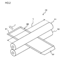
- the pre-registration rollers 13 are composed of an upper roller 31 and a lower roller 32, each roller having a predetermined roller width (longitudinal length) L shown in FIG. 2 .
- the roller width L defines a region (hereinafter, referred to as "sheet-conveying region") along a width direction of the sheet of paper P, is longer than a width of the envelope 50 and is a length that is equal to a sheet width of the sheet of paper with maximum size which is able to be contained in the trays 4 through 6.
- the upper roller 31 is a long driven roller which is one roller and the lower roller 32 is a long driving roller which is one roller.
- the pre-registration rollers 13 are configured by the upper roller 31 and the lower roller 32, each of which is one rod-like roller and has a uniform roller diameter within the sheet-conveying region.
- the loop rollers 14 are arranged at an upstream side of the pre-registration rollers 13 along the sheet-conveying direction.
- the loop rollers 14 operate to hit the envelope 50 against the pre-registration rollers 13 to allow the envelope 50 to flex so that the posture of the envelope 50 can be corrected.
- the closed portion the envelope 50 which is opposite side of the opened portion of the envelope, is hit against a nip portion between the upper roller 31 and the lower roller 32, which are stopped, by driving the loop rollers 14. This enables the closed portion of the envelope 50 to be corrected to a direction which is almost perpendicular to the sheet-conveying direction (Pre-registration function).
- the pre-registration rollers 13 then drive so that the envelope 50 passes through the nip portion so as to be conveyed on the sheet-conveying path 12 with the envelope being nipped by the upper roller 31 and the lower roller 32.
- This enables air to be removed from the envelope 50 by nipping the envelope 50 by the upper roller 31 and the lower roller 32 of the pre-registration rollers 13.
- the air may be removed from the envelope 50 so that flatness of the envelope 50 is enhanced to improve print quality (first envelope corresponding control example).
- the feeder 20 contains a sheet-switching portion 21, a sheet-conveying path 22, pre-registration rollers 23 and loop rollers 24. Since the elements of the feeder 20 having like name of these of the feeder 10 have like functions, the detailed explanation thereof will be omitted.
- the tray 9 corresponds to the envelope mode in the feeder 20.
- the color copy machine 100 constituting an image forming apparatus is connected to the above-mentioned feeder 10 at a downstream side thereof along the sheet-conveying direction.
- the color copy machine 100 includes a main body 101 thereof.
- the main body 101 of the color copy machine 100 contains a feeding portion 30, an image forming portion 41, an intermediate transfer belt 42, a fixing portion 43, a scanner 44, a control portion 45 and a manipulation/display portion 46.
- the feeding portion 30 is installed at a predetermined position in the main body 101 of the color copy machine 100.
- the feeding portion 30 contains three layered strays 1 through 3. Each of the trays 1 through 3 contains sheets of paper with a predetermined size and each of the trays 1 through 3 feeds the sheet of paper with the predetermined size to the image forming portion 41 similar to the two feeders 10, 20.
- the scanner 44 and the manipulation/display portion 46 are positioned on the main body 101 of the color copy machine 100.
- the manipulation/display portion 46 allows a user to manipulate a screen thereof to set the envelope mode and/or image forming conditions.
- the image forming conditions include normal node/envelope mode, printing mode (single-side printing/duplex printing), a species of the sheet such as the sheet of paper P and the envelope 50, their paper weight, the trays 4 through 9, image forming mode (monochrome/color), a sheet size, an envelope size, page number, a number of copies and the like.
- the scanner 44 contains a line image sensor (hereinafter, referred to as "CCD") constituting a document image scanning and exposing apparatus, not shown.
- CCD line image sensor
- the CCD reads the document based on the read instruction from the manipulation/display portion 46 and outputs the read image data to the control portion 45.
- the image forming device 40, the fixing portion 43 and the control portion 45 are installed at predetermined positions in the main body 101 of the color copy machine 100.
- the image forming device 40 contains registration rollers 33, loop rollers 34, the image forming portion 41 and the intermediate transfer belt 42.
- the image forming portion 41 receives the image data from the control portion 45 and forms a color image or a black/white image on the sheet of paper P, the envelope 50 or the like fed from the feeding portion 30, the feeders 10, 20 and the like based on an image forming job.
- the image forming portion 41 ejects the sheet of paper P or the envelope 50, on which the color or black/white image has been formed, to the intermediate unit 200.
- the image forming portion 41 uses, for example, an electrophotographic printer engine of tandem type.
- the image forming portion 41 converts image data of RGB system to image data of YMCK system.
- the image forming portion 41 forms a color toner image based on the image data on the converted yellow (Y), the converted magenta (M), the converted cyan (C) and the converted black (BK).
- the image forming portion 41 contains image forming units respectively taking charge of the forming of the images of Y, M, C and BK colors.
- a charging unit uniformly charges the photosensitive drum for every image forming color.
- the charged photosensitive drum is exposed and an electrostatic latent image can be formed on the photosensitive drum based on image data.
- the developing device develops the electrostatic latent image for every image-forming color. These charge, exposure and development are performed for every image-forming color so that each toner image can be formed on the photosensitive drums on every image-forming color.
- the formed toner images are fitted on each other on the intermediate transfer belt 42.
- the transfer portion transfers the fitted color toner images on the sheet of paper P, the envelope 50 or the like.
- the process conditions such as the development, the transfer and the like are changed to process conditions that are special to the envelope printing in which the envelope 50 is printed.
- the registration rollers 33 and the loop rollers 34 are arranged on the feeding portion 30. Since these functions are the same as the functions of the pre-registration rollers 13 and the loop rollers 14, the explanation thereof will be omitted.
- the sheet of paper P is conveyed from the trays 4, 5 of the feeder 10 and the trays 7, 8 of the feeder 20 to the transfer portion.
- the envelope 50 is conveyed from the tray 6 of the feeder 10 and the tray 9 of the feeder 20 to the transfer portion.
- the fixing portion 43 fixes the toner image transferred on the desired sheet of paper P, the desired envelope 50 or the like.
- the fixing condition is changed to the fixing condition that is special to the envelope printing in which the envelope 50 is printed.
- the fixed sheet of paper P or the fixed envelope 50 is ejected from the color copy machine 100. This enables the color image or the black/white image based on the image data to be formed on the desired sheet of paper P or the desired envelope 50.
- the intermediary unit 200 is connected to the color copy machine 100 at a downstream side thereof along the sheet-conveying direction.
- the intermediary unit 200 stacks the sheets of paper P and/or the envelopes 50, on which the image has been formed, ejected from the color copy machine 100. In such a stacking process, plural sheets of paper P and/or plural envelopes 50, on which the image has been formed, are bundled.
- the finishing apparatus 300 is connected to the intermediary unit 200 at a downstream side thereof along the sheet-conveying direction.
- the finishing apparatus 300 performs, for example, a staple processing on the bundle of sheets of paper P.
- the finishing apparatus 300 then ejects stapled booklets.
- the tray 6 corresponding to the envelope has the air suction mechanism as shown in FIG. 3 .
- the air suction mechanism operates to allow the top sheet of paper P (or the top envelope 50) of the sheets of paper P (the stacked envelopes 50) mounted on a sheet-mounting base 90, which can be elevated, to float and to be sucked.
- the air suction mechanism also operates to allow the floated and sucked sheets of paper P or envelopes 50 to be sent in order (air suction function).
- the tray 6 contains air-blowing side portions 60 and a sheet-sucking-and-conveying portion 80.
- the air-blowing side portions 60 blow air to the sides of the bundle of the sheets of paper P or the like from each side (as shown by arrows IIa and IIb in white on x direction) along a sheet width direction x (which is almost perpendicular to the sheet-conveying direction y) in order to allow the top sheet of paper P or the like to float upward on the sheet-mounting base 90 (along a sheet thickness direction z, namely, vertical direction z, which is perpendicular to each of the directions x and y).
- Each of the air-blowing side portions 60 contains a duct main body 61, a telescopic duct 62, an air-blowing-opening-elevating portion 64 and the like.
- the duct main body 61 and the telescopic duct 62 lead the air for allowing the top sheet of paper or the like to float to an air-blowing opening.
- a bent guide portion 63 is arranged on the telescopic duct 62 so as to be positioned in an upper part of the air-blowing opening.
- Each of the air-blowing side portions 60 blows the air to the side of the bundle of the sheets of paper P or the like along the guide portion 63, as shown by arrows IIa and IIb in white of FIG. 3 .
- the air-blowing-opening-elevating portion 64 is provided on the back surface of each of the air-blowing side portions 60.
- the air-blowing-opening-elevating portion 64 elevates the telescopic duct 62 and the guide portion 63, which communicate the air-blowing opening to decide an air blowing position, vertically (along the sheet thickness direction z).
- the sheet-sucking-and-conveying portion 80 is arranged over the sheets of paper or the like mounted on the sheet-mounting base 90.
- the sheet-sucking-and-conveying portion 80 sucks the floated sheet of paper P or the like based on the air IIa, IIb using suction air III and conveys it in order.
- the sheet-sucking-and-conveying portion 80 contains a pair of conveying belts 81, 81.
- Each of the conveying belts 81, 81 sucks the top sheet of paper P or the like of the sheets of paper or the like mounted on the sheet-mounting base 90.
- the pair of conveying belts 81, 81 conveys the sucked top sheet of paper P or the like to the color copy machine 100 in order.
- the sheet-sucking-and-conveying portion 80 also contains driving rollers 82 and guide rollers 83, 84 and 85 in addition to the conveying belts 81, 81.
- Belt-driving portion not shown, rotates the conveying belts 81, 81 clockwise to run on the driving rollers 82 and the guide rollers 83, 84 and 85.
- the sheet-mounting base 90, the air-blowing side portions 60, the air-blowing-opening-elevating portion 64 and the sheet-sucking-and-conveying portion 80 constitute a sheet-sucking-and-conveying system.
- the sheet-sucking-and-conveying system which is similar to that of the tray 6 is also constituted.
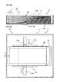
- FIG. 4A shows an appearance of the back side of the envelope 50.
- the envelope 50 is composed of, for example, folded and glued parts 50a, 50b and 50c and a seal part 50d.
- the folded and glued parts 50a, 50b and 50c sheets for envelope are overlapped trebly.
- the folded and glued parts 50a, 50b and 50c have thickness thicker than that of the seal part 50d.
- the seal part 50d constitutes an opened portion 52 of the envelope 50
- the folded and glued part 50b which is opposite side of the opened portion 52 of the envelope 50, constitutes a closed portion 51 of the envelope 50.
- the tray 6 or the like contains the envelopes 50 with the opened portions 52 of the envelopes 50 facing to the upstream side along the sheet-conveying direction and being aligned.
- any air suction function is applied to the above-mentioned tray 6 or the like corresponding to the envelope, it is configured that if air enters into the envelope 50 through the opened portions 52 thereof accidentally, the pre-registration rollers 13 removes the air from the envelope 50.
- a name and an address of the sender are normally printed by monochrome ink as shown in FIG. 4A .
- a name and an address of a destination, logo mark of the company or business which sends the envelope, and/or illustrated image(s) including a company name or a company address are often printed in color.
- the thickness of the bundle of the envelopes 50 becomes thicker at the side of the closed portions 51 thereof than that of the side of the opened portions 52 thereof because the closed portion 51 of each of the envelopes 50 have folded parts (see FIG. 5A ).
- the stacked envelopes 50 may be inclined. Accordingly, an envelope special kit 70 is prepared in order to correct the inclination of the envelope 50 and to maintain the flatness of the top envelope 50.
- a tray main body 71 is provided with a height-adjusting member 72 and special guide plates (guide members) 73a, 73b.
- the sheet-mounting base 90 mounts the tray main body 71 and the height-adjusting member 72 is provided in the tray main body 71.
- the envelopes 50 are contained on the height-adjusting member 72 in the tray 6 with the opened portions 52 of the envelopes 50 facing to the upstream side along the sheet-conveying direction and being aligned.
- the height-adjusting member 72 adjusts a height of the bundle of the envelopes 50 mounted in the tray main body 71.
- a raised bottom plate having a triangular section and a gentle down slope inclined along a direction (the sheet-conveying direction) from the opened portions 52 of the envelopes 50 to the closed portion 51 thereof is used.
- an upper surface of the height-adjusting member 72 may be formed so as to be a circular arc on the width direction of the envelope 50.
- Such an arc-shaped member can smooth out the thickness increased by the folded parts of both sides of the envelope 50 to cancel the influence by the increased thickness thereof.
- the special guide plates 73a, 73b are installed in openings 74a, 74b provided on a bottom surface of the tray main body 71 along the sheet width direction so as to be slidable.
- the special guide plates 73a, 73b guide the envelopes 50, a height of which is adjusted by the height-adjusting member 72, to a predetermined direction.
- a user adjusts the envelopes 50 so that the special guide plates 73a, 73b push sides of the bundle of the envelopes 50 along the openings 74a, 74b.
- whole of the PP system #1 is configured.
- the control portion 45 is configured so as to automatically set air-removing conditions according to the coverage rate of the image to be printed on the envelope 50 when setting the envelope mode.
- the color copy machine 100 controls inputs/outputs of the feeders 10, 20, the intermediary unit 200 and the finishing apparatus 300.
- the color copy machine 100 contains the feeding portion 30, the image forming device 40, the fixing portion 43, the control portion 45 and the manipulation/display portion 46.
- control portion 45 control a conveying speed of the envelope 50 (this envelope is shown as the envelope H in FIG. 6 ) based on the coverage of the image to be formed on the envelope 50 by the image forming portion 41.
- control portion 45 receives the setting of the envelope mode and controls rotation speed of the pre-registration rollers 13 based on the coverage rate of the received setting of envelope mode to adjust the conveying speed of the envelope 50.
- This enables the conveying speed of the envelope 50 to be changed (to variable speed pattern or intermittent pattern) according to printing contents (coverage, printing position or the like) of the image to be printed on the envelope 50 (second envelope corresponding control example).
- the control portion 45 receives (acquires), for example, information about the coverage rate of the image to be printed on the envelope 50. Since the information about the coverage rate is described in header information constituting an image forming job during the envelope mode, the control portion 45 may acquires the information about the coverage rate by decoding the header information.
- the control portion 45 compares the coverage rate of the image to be formed on the envelope 50 with a previously set threshold value of the coverage rate as a discriminant criterion thereof. When the coverage rate of the image to be formed on the envelope is low coverage rate so that it does not exceed the threshold value, the control portion 45 sets the conveying speed of the envelope 50 so as to be (almost) the same speed as the normal conveying speed of the sheet of paper P (the normal conveying speed).
- control portion 45 controls the feeder 10 to feed the envelope 50 from the tray 6 to the pre-registration rollers 13 at a sheet-conveying speed corresponding to the envelope and to feed the envelope 50 without decreasing the conveying speed of the envelope thereafter, which enhances productivity.
- control portion 45 sets the conveying speed of the envelope 50 so as to be slower than the normal conveying speed of the sheet of paper P (variable speed pattern).
- control portion 45 controls the pre-registration rollers 13 to drive and stop them or to decrease the sheet-conveying speed so that the air can be removed from the envelope 50.
- control portion 45 controls the pre-registration rollers 13 to perform an intermittent rotation (the intermittent pattern) so that the envelope 50 is intermittently conveyed to remove the air from the envelope 50.
- an intermittent rotation the intermittent pattern
- the feeder 10 contains a sheet-switching portion 11, a feeding control portion 17 and a motor-driving portion 18. To the above-mentioned control portion 45, the feeding control portion 17 of the feeder 10 is connected through a special communication cable, not shown. The feeding control portion 17 decodes feeding control data D11 to generate a tray selection signal S11 and a motor control signal S18.
- the feeding control data D11 is information for controlling the feeder 10 and the control portion 45 outputs the feeding control data D11 to the feeding control portion 17.
- the feeding control portion 17 is connected to the sheet-switching portion 11.
- the sheet-switching portion 11 selects any one of the trays 4 through 6 based on the tray selection signal S11 and connects the selected tray to the sheet-conveying path 12.
- the sheet-switching portion 11 selects the tray 6 and connects it to the sheet-conveying path 12.
- the motor-driving portion 18 is connected in addition to the sheet-switching portion 11.
- the motor-driving portion 18 rotates the pre-registration rollers 13 at a sheet-conveying speed of the sheet of paper P which corresponds to the setting of the sheet-conveying speed to 1/1 or 1/2 based on the motor control signal S18 to convey the envelope 50 on the sheet-conveying path 12.
- the feeding control portion 17 controls the motor-driving portion 18 to perform an intermittent rotation control to repeat operations to rotate the pre-registration rollers 13 by a predetermined angle and then to stop the rotation thereof.
- the feeder 20 contains the sheet-switching portion 21, the feeding control portion 27 and the motor-driving portion 28. Since the elements of the feeder 20 having like name of these of the feeder 10 have like functions, the detailed explanation thereof will be omitted.
- the sheet-switching portion 21 is provided at downstream side of the trays 7 through 9 along the sheet-conveying direction. The sheet-switching portion 21 selects any one of the trays 7 through 9 based on feeding control data D21 and connects the selected tray to the straight feeding path 15 of the feeder 10.
- the feeding portion 30 is connected to the control portion 45.
- the control portion 45 controls the feeding portion 30 to select any of the trays 1 through 3 based on the feeding control data D30 to convey the sheet of paper P to the image forming device 40 therefrom.
- the feeding control data D30 is data for selecting any of the trays 1 through 3 and the control portion 45 outputs the feeding control data D30 to the feeding portion 30.
- the image forming device 40 forms a color image based on image data Dy, Dm, Dc, Dk and an image forming control signal S40.
- the image data Dy, Dm, Dc, and Dk is data for forming the color image, which is obtained by performing any image processing on image read data Din obtained from the scanner 44, on the sheet of paper P or the envelope 50.
- the image forming control signal S40 is a signal for controlling image forming timing in the image forming device 40.
- the control portion 45 outputs the image data Dy, Dm, Dc, Dk and the image forming control signal S40 to the image forming device 40.
- the fixing portion 43 fixes the sheet of paper P or the envelope 50, on which the image has formed, based on a fixing control signal S43.
- a fixing device is exchanged to a special fixing device for fixing the envelope 50.
- the fixing control signal S43 is a control signal used when the toner image is fixed which is transferred to the sheet of paper P or the envelope 50.
- the control portion 45 outputs the fixing control signal S43 to the fixing portion 43.
- the manipulation/display portion 46 is connected to the control portion 45.
- the user manipulates the manipulation/display portion 46 to select, when setting the sheet of paper, any of the trays 1 through 3 of the feeding portion 30 containing the sheets of paper P, any of the trays 4, 5 of the feeder 10, any of the trays 7, 8 of the feeder 10, the tray 6 corresponding to the envelope in the feeder 10, the tray 9 corresponding to the envelope in the feeder 20 or the like.
- the manipulation/display portion 46 outputs to the control portion 45 manipulation data D46 containing tray selection instruction, the envelope mode, image forming conditions (process conditions) and the like. In the envelope mode, feeding conditions, image forming conditions and/or the like are changed to the envelope special conditions and setting items for the envelope mode can be set.
- control portion 45 outputs intermediary control data D20 to the intermediary unit 200 to perform a stack control and the control portion 45 outputs finishing control data D33 to the finishing apparatus 300 to perform a finishing control.
- control system of the PP system #1 is configured.
- control portion 45 receives setting of the envelope mode in which the conveying speed of the envelope 50 is controlled based on a coverage rate of the image to be formed on the envelope 50.
- the control portion 50 adjusts a rotation speed of the pre-registration rollers 13 based on the coverage rate of the received envelope mode to control the conveying speed of the envelope 50.
- the upper roller 31 and the lower roller 32 used in the pre-registration rollers 13 of the feeder 10 or the pre-registration rollers 23 of the feeder 20 nip the envelope 50 to remove the air from the envelope 50.
- the control portion 45 receives setting of the envelope mode or the normal mode.
- the user manipulates the manipulation/display portion 46 to set the envelope mode or the normal mode.
- the tray 6 or 9 is selected. In this embodiment, the tray 6 corresponding to the envelope is selected.
- any of the trays 1 through 5, 7 and 8 is selected.
- the user also sets paper weight of the sheet of paper P.
- the control portion 45 sets the sheet-conveying speed to 400 mm/s (corresponding to the normal sheet-conveying speed (1/1)).
- the control portion 45 sets the sheet-conveying speed to 300 mm/s (corresponding to three fourths (3/4) of the normal sheet-conveying speed).
- the control portion 45 sets the sheet-conveying speed to 200 mm/s (corresponding to a half (1/2) of the normal sheet-conveying speed).
- the control portion 45 sets the conveying speed of the envelope to a half (1/2) of the normal sheet-conveying speed.
- the control portion 45 determines whether or not the envelope mode is set.
- the control portion 45 determines whether or not a high coverage printing is used based on the image to be formed on the envelope 50.
- the envelope is the envelope 50 shown in FIG.4B
- the high coverage printing is used based on the image of the front surface of this envelope 50.
- the control portion 45 controls the pre-registration rollers 13 to set the conveying speed of the envelope to a half of the normal sheet-conveying speed.
- the control portion 45 outputs to the feeding control portion 17 the feeding control data D11 such that the conveying speed of the envelope is set to a half of the normal sheet-conveying speed.
- the feeding control portion 17 decodes the feeding control data D11 to generate the motor control signal S18 such that the conveying speed of the envelope is set to a half of the normal sheet-conveying speed.
- the motor driving portion 18 rotates the pre-registration rollers 13 at the conveying speed of the envelope, which corresponds to a half of the normal sheet-conveying speed, based on the motor control signal S18. This enables the envelope 50 to be conveyed on the sheet-conveying path 12 at the conveying speed of the envelope, 200 mm/s, which corresponds to a half of the normal sheet-conveying speed. In this moment, the envelope 50 is nipped by the pre-registration rollers 13 to remove the air from the envelope 50 slowly and carefully.
- the control portion 45 controls the image forming device 40 to print the image under the envelope mode.
- the image forming device 40 forms the color image on the envelope 50 conveyed by the pre-registration rollers 13 based on the image data Dy, Dm, Dc, Dk and the image forming control signal S40.
- the control portion 45 also control the fixing portion 43 to fix the envelope 50 on which the color image has been formed based on the fixing control signal S43.
- the control portion 45 outputs the intermediary control data D20 to the intermediary unit 200 to perform a stack control.
- control portion 45 determines that a high coverage printing is not used based on the image to be formed on the envelope 50, namely, a low coverage printing is used, at a step ST5, the control portion 45 controls the pre-registration rollers 13 to set the conveying speed of the envelope to the normal sheet-conveying speed (1/1). In this moment, the control portion 45 outputs to the feeding control portion 17 the feeding control data D11 such that the conveying speed of the envelope is set to the normal sheet-conveying speed.
- the feeding control portion 17 decodes the feeding control data D11 to generate the motor control signal S18 such that the conveying speed of the envelope is set to the normal sheet-conveying speed (1/1).
- the motor driving portion 18 rotates the pre-registration rollers 13 at the conveying speed of the envelope, which corresponds to the normal sheet-conveying speed (1/1), based on the motor control signal S18. This enables the envelope 50 to be conveyed on the sheet-conveying path 12 at the conveying speed of the envelope, 400 mm/s, which corresponds to the normal sheet-conveying speed (1/1). In this moment, the envelope 50 is nipped by the pre-registration rollers 13 to remove the air from the envelope 50 faster than a case of the high coverage printing.
- control portion 45 then controls the image forming device 40 to print the image under the envelope mode and controls the fixing portion 43, the intermediary unit 200 and the like (see the above-mentioned step ST6).
- the control portion 45 determines that the normal mode is set
- the control portion 45 controls the pre-registration rollers 13 to set the sheet-conveying speed according to the paper weight of the sheet of paper. For example, when the paper weight is within a range of 136 through 300 g/m 2 , the control portion 45 sets the sheet-conveying speed to 300 mm/s (corresponding to three fourths (3/4) of the normal sheet-conveying speed).
- the control portion 45 outputs to the feeding control portion 17 the feeding control data D11 such that the sheet-conveying speed of the sheet of paper P is set to three fourths (3/4) of the normal sheet-conveying speed.
- the feeding control portion 17 decodes the feeding control data D11 to generate the motor control signal S18 such that the sheet-conveying speed of the sheet of paper P is set to three fourths (3/4) of the normal sheet-conveying speed.
- the motor driving portion 18 rotates the pre-registration rollers 13 at the sheet-conveying speed of the sheet of paper P, which corresponds to three fourths (3/4) of the normal sheet-conveying speed, based on the motor control signal S18.
- the control portion 45 then controls the image forming device 40 to print the image under the normal mode.
- the control of the feeders 10, 20 based on the automatic setting of the air-removing conditions corresponding to the coverage rate of the image is finished.
- the PP system #1 as an embodiment of the invention is provided with the feeders 10, 20 according to an embodiment of the invention so that if the tray 6 containing the envelopes 50 is selected, when conveying the envelope 50, the posture of the envelope 50 is corrected by hitting the closed portion 51 of the envelope 50, which is opposite side of the opened portion 52 of the envelope 50, against a nip portion between the upper roller 31 and the lower roller 32 and the envelope 50 is then conveyed with the envelope 50 being nipped by the upper roller 31 and the lower roller 32.
- each of the feeders 10, 20 is provided with the pre-registration rollers 13 each having a roller width (longitudinal length) L which is longer than a width of the envelope 50, each of the surfaces of the rollers contacts the envelope 50 along the overall width length of the envelope 50 so that it is possible to carry out the air-removing operation from the envelope 50 reproducibly.
- the pre-registration rollers 13 can correct the posture of the envelope 50 and can remove the air from the envelope 50 reproducibly by its nipping portion.
- the tray 6 or the like containing the envelopes 50 is provided with the height-adjusting member 72 and the special guide plates 73a, 73b so that when the envelope 50 is sent using the air suction function, it is possible to convey the envelope 50 to the pre-registration rollers 13 so that the height-adjusted top envelope 50 floats and is sucked and the floated and sucked envelope 50 is guided toward a direction of the sheet-conveying path 12.
- the control method of the feeder 10 or 20, and the PP system #1 it is possible to remove the air from the envelope 50 at the conveying speed of the envelope based on the coverage rate of the image to be formed on the envelope 50 because the control portion 45 controlling the conveying speed of the envelope 50 adjusts the rotation speed of the pre-registration rollers 13 based on the coverage rate of the set envelope mode.
- This enables the envelope mode to be performed with maintaining better productivity than that of a case where the conveying speed of the envelope 50 is decreased less than the sheet-conveying speed of the sheet of paper P without variation.
- the coverage rate of the image to be formed on the envelope 50 is compared with a threshold value of the coverage rate as a discriminant criterion thereof and when the coverage rate of the image to be formed on the envelope 50 exceeds the threshold value, the conveying speed of the envelope 50 is set to be slower than a normal conveying speed of the sheet of paper P, so that it is possible to perform the operation of removing the air from the envelope 50 while the envelope 50 is passed through the pre-registration rollers 13 during a longer period of time than the normal passing period of time of the sheet of paper.
- the control portion 45 carries out the intermittent rotation control so that it is possible to surely carry out the operation to remove the air from the envelope 50 by stages as compared with the case where the normal sheet of paper is passed through the pre-registration rollers 13.
- the feeders 10, 20 each corresponding to the envelope mode connect the color copy machine 100 in series, it is possible to remove the air from the envelope 50 in every feeder. It is also possible to surely remove the air from the envelope 50, from which the air has been already removed in the feeder 20 of the upstream side, in the feeder 10 of the downstream side when the envelope 50 is conveyed from the feeder 20 of the upstream side to the image forming device 40.
- This invention is preferably applied to the PP system in which a large capacity of multiple feeders is connected to a color printer, a black/white printer, a copying machine, a multifunction printer thereof or like.
Landscapes
- Physics & Mathematics (AREA)
- General Physics & Mathematics (AREA)
- Engineering & Computer Science (AREA)
- Mechanical Engineering (AREA)
- Sheets, Magazines, And Separation Thereof (AREA)
- Registering Or Overturning Sheets (AREA)
- Paper Feeding For Electrophotography (AREA)
- Laser Beam Printer (AREA)
- Delivering By Means Of Belts And Rollers (AREA)
Abstract
Description
- The present invention relates to a control method of feeder and an image forming system, which are applied to a production print system (hereinafter, referred to as "PP System").
- In the recent year, the PP system in which large capacity multiple feeders are connected to a color printer, a black/white printer, a copying machine, a multifunction printer thereof or like has been often used in a commercial printing field and/or a printing section in an enterprise. The PP system forms a large number of printed matters including envelopes.
- By the way, in the PP system, an attempt to print an illustration of a corporate logo, a corporation name or the like on a plain envelope and then, to execute an image forming job (envelope mode) for printing an address and a destination respectively on the envelope has been made. In order to enable plural species of envelopes to be printed, the feeder corresponding to the plural species of envelopes is desirable for the feeder to be connected to the image forming apparatus.
- On the other hand, a demand for the high performance and large capacity feeder has been increased. A feeder having an air suction function to enable sheets of paper to float one by one, enable the top sheet of paper to be sucked and enable the sucked sheet of paper to be conveyed to an image forming apparatus has been manufactured.
- Regarding the feeder corresponding to the envelope, Japanese Patent Application Publication No.
2011-037486 - When setting the envelope mode in the past PP system to print an image, an address and the like on the envelope, the past PP system may deteriorate its print quality on the envelope because the envelope includes an opening and an air enters thereto through the opening so that transfer quality of the image and the like becomes worse and any creases occur. Particularly, when the feeder with the air suction function performs the envelope mode, the air may accidentally enter into the envelope so that an action to remove the air from the envelope is required.
- When a method of ejecting the envelope by intermittently repeating the driving and stopping the rollers, which has been disclosed in Japanese Patent Application Publication No.
2011-037486 - This invention addresses the above-mentioned issues and has an object to provide an improved control method of feeder and an improved image forming system, which are capable of removing the air from the envelope reproducibly and enhancing flatness of the envelope before the image and the like are printed on the envelope.
- To achieve at least one of the above-mentioned objects, a control method of a feeder reflecting one aspect of the present invention, the feeder including a feeding portion which stores a sheet of paper containing an envelope with a predetermined size and feeds the stored sheet of paper, the envelope containing an opened portion and a closed portion, and a pair of registration rollers containing an upper roller and a lower roller, each roller having a longitudinal length longer than a width of the fed sheet of paper, the registration rollers correcting a posture of the sheet of paper fed from the feeding portion to convey the sheet of paper toward a downstream side along a sheet-conveying direction, wherein, when conveying the envelope, the posture of the envelope is corrected by hitting the closed portion of the envelope, which is opposite side of the opened portion of the envelope, against a nip portion between the upper and lower rollers of the registration rollers and the envelope is then conveyed with the envelope being nipped by the upper and lower rollers of the registration rollers, contains a setting step of setting an envelope mode to control a conveying speed of the envelope based on a coverage rate of an image to be formed on the envelope, and a control step of controlling the conveying speed of the envelope by adjusting a rotation speed of the registration rollers based on the coverage rate of the envelope mode set in the setting step.
- In this invention, when conveying the envelope, the posture of the envelope is corrected by hitting the closed portion of the envelope, which is opposite side of the opened portion of the envelope, against a nip portion between the upper and lower rollers of the registration rollers. The envelope is then conveyed with the envelope being nipped by the upper and lower rollers of the registration rollers. The envelope mode to control a conveying speed of the envelope based on a coverage rate of an image to be formed on the envelope is set. The conveying speed of the envelope is controlled by adjusting a rotation speed of the registration rollers based on the coverage rate of the envelope mode.
- Further, to achieve at least one of the above-mentioned objects, an image forming system reflecting another aspect of the present invention contains a feeder including a feeding portion which stores a sheet of paper containing an envelope with a predetermined size and feeds the stored sheet of paper, the envelope containing an opened portion and a closed portion, and a pair of registration rollers containing an upper roller and a lower roller, each roller having a longitudinal length longer than a width of the fed sheet of paper, the registration rollers correcting a posture of the sheet of paper fed from the feeding portion to convey the sheet of paper toward a downstream side along a sheet-conveying direction, wherein, when conveying the envelope, the posture of the envelope is corrected by hitting the closed portion of the envelope, which is opposite side of the opened portion of the envelope, against a nip portion between the upper and lower rollers of the registration rollers and the envelope is then conveyed with the envelope being nipped by the upper and lower rollers of the registration rollers; an image forming device which forms the image on the envelope fed from the feeder, the image forming device connecting the feeder, and a control portion which controls the feeder corresponding to an envelope mode in which the conveying speed of the envelope is controlled based on a coverage rate of the image to be formed on the envelope by the image forming device, wherein the control portion is configured as to receive setting of the envelope mode and to control the conveying speed of the envelope by adjusting a rotation speed of the registration rollers based on the coverage rate of the received envelope mode.
- The image forming device connected to the feeder forms an image on the envelope fed from the feeder. The control portion controls the feeder corresponding to the envelope mode in which the conveying speed of the envelope is controlled based on a coverage rate of the image to be formed on the envelope by the image forming device. The control portion is configured as to receive setting of the envelope mode and to control the conveying speed of the envelope by adjusting a rotation speed of the registration rollers based on the coverage rate of the received envelope mode.
- According to the control method of the feeder of this invention, it is possible to remove the air from the envelope reproducibly and to enhance the flatness of the envelope before the image forming. It is also possible to maintain good printing quality of the envelope because the image is formed on the flatness enhanced envelope.
- According to the control method of the feeder of this invention, it is also possible to perform the operation of removing the air from the envelope surely while the envelope is passed through the registration rollers during a longer period of time than the normal passing period of time of the sheet of paper.
- According to the control method of the feeder of this invention, it is further possible to surely carry out the operation to remove the air from the envelope by stages as compared with the case where the normal sheet of paper is passed through the registration rollers.
- According to the image forming system of this invention, it is possible to remove the air from the envelope at the conveying speed of the envelope based on the coverage rate of the image to be formed on the envelope. This enables the envelope mode to be performed faster than that of a case where the conveying speed of the envelope is decreased without variation.
- According to the image forming system of this invention, it is also possible to perform the operation of removing the air from the envelope surely while the envelope is passed through the registration rollers during a longer period of time than the normal passing period of time of the sheet of paper.
- According to the image forming system of this invention, it is further possible to surely carry out the operation to remove the air from the envelope by stages as compared with the case where the normal sheet of paper is passed through the registration rollers.
- According to the image forming system of this invention, it is additionally possible to remove the air from the envelope in every feeder. It is also possible to surely remove the air from the envelope, from which the air has been already removed in the feeder of the upstream side, in the feeder of the downstream side when the envelope is conveyed from the feeder of the upstream side to the image forming device.
- The concluding portion of this specification particularly points out and directly claims the subject matter of the present invention. However, those skilled in the art will best understand both the organization and method of operation of the invention, together with further advantages and objects thereof, by reading the remaining portions of the specification in view of the accompanying drawing (s) wherein like reference characters refer to like elements.
-
-
FIG. 1 is a diagram for showing a configuration example of a production print (PP) system as an embodiment of this invention; -
FIG. 2 is a perspective view of pre-registration rollers showing an example of removing air from the envelope; -
FIG. 3 is a perspective view of a tray showing a configuration example of an air suction mechanism; -
FIG. 4A is a diagram showing an appearance example of a back side of the envelope andFIG. 4B is a diagram showing an appearance example of a front side of the envelope; -
FIG. 5A is a sectional view of an envelope special kit in the tray andFIG. 5B is a front view of the envelope special kit in the tray; -
FIG. 6 is a block diagram of the PP system showing a configuration example of a control system thereof; and -
FIG. 7 is a flowchart for showing a control example of the PP system when it corresponds to an envelope mode. - The following will describe a feeder, a control method of the feeder and an image forming system as the preferred embodiments to carry out the invention with reference to drawings.
- A production print system (PP system #1) shown in
FIG. 1 constitutes an image forming system. ThePP system # 1 is a system for producing a large amount of printed matters including envelopes, in which a color printer, a black/white printer, a copy machine, a multifunction apparatus and the like are connected with large capacity feeder(s). - The
PP system # 1 contains acolor copy machine 100, twofeeders intermediary unit 200 and afinishing apparatus 300. In the envelope mode, a tray containing envelopes of a predetermined size is selected, the envelopes are dispatched one by one and an image is formed on each of the dispatched envelopes. The feeder (a first paper feed unit (PFU)) 10 and the feeder (a second paper feed unit (PFU)) 20 are configured as to be able to connect thecolor copy machine 100. The feeders are not limited to two in the PP system #1: The feeder more than two feeders may connect thecolor copy machine 100 in series. - In each of the
feeder layered trays 4 through 6 are provided in thefeeder 10. Thetrays 4 through 6 contain sheets of paper P with a predetermined size or envelopes 50 (seeFIGS. 4A and 4B ) with a predetermined size. Thefeeder 10 feeds the sheet of paper P or theenvelope 50. - The
feeder 10 includes a sheet-switching portion 11, a sheet-conveying path 12, thepre-registration rollers 13,loop rollers 14 and astraight feeding path 15 in addition to threelayered trays 4 through 6. In this embodiment, twotrays straight feeding path 15 and thetray 6 corresponding to the envelope is arranged below thestraight feeding path 15. - The reason why the
tray 6 corresponding to the envelope is arranged below thestraight feeding path 15 is because a dispatching path from thelower tray 6 corresponding to the envelope to the sheet-conveying path 12 is gentler than a dispatching path, which is at about right angles, from theupper trays lower tray 6 is weaker than that applied to the conveying envelope on theupper trays tray 6 with opened portions of the envelopes being aligned and facing toward an upstream side along a sheet-conveying direction. - The sheet-switching
portion 11 is positioned at a downstream side of the above-mentionedtrays 4 through 6 along the sheet-conveying direction. The sheet-switchingportion 11 selects any one of thetrays 4 through 6, based on information for controlling the feeding, to connect the selected tray to the sheet-conveying path 12. The sheet-switchingportion 11 is provided with gate switching plates, solenoid as driving source and the like, which are not shown. The sheet-conveying path 12 extends from the sheet-switchingportion 11 to thecolor copy machine 100. The sheets of paper or theenvelopes 50 are conveyed on the sheet-conveying path 12 at their predetermined conveying speed. There are plural conveying rollers, not shown, on the sheet-conveying path 12. - The
pre-registration rollers 13 constituting the registration rollers are arranged on the way to the sheet-conveying path 12. Thepre-registration rollers 13 correct a posture of the sheet of paper fed from thetray portion 11 or theenvelope 50 fed from thetray 6 selected by the sheet-switchingportion 11. Thepre-registration rollers 13 are connected with amotor driving portion 18 shown inFig. 6 . Themotor driving portion 18 drives thepre-registration rollers 13 to rotate them to predetermined directions. - The
pre-registration rollers 13 are composed of anupper roller 31 and alower roller 32, each roller having a predetermined roller width (longitudinal length) L shown inFIG. 2 . The roller width L defines a region (hereinafter, referred to as "sheet-conveying region") along a width direction of the sheet of paper P, is longer than a width of theenvelope 50 and is a length that is equal to a sheet width of the sheet of paper with maximum size which is able to be contained in thetrays 4 through 6. Theupper roller 31 is a long driven roller which is one roller and thelower roller 32 is a long driving roller which is one roller. Thus, thepre-registration rollers 13 are configured by theupper roller 31 and thelower roller 32, each of which is one rod-like roller and has a uniform roller diameter within the sheet-conveying region. - The
loop rollers 14 are arranged at an upstream side of thepre-registration rollers 13 along the sheet-conveying direction. Theloop rollers 14 operate to hit theenvelope 50 against thepre-registration rollers 13 to allow theenvelope 50 to flex so that the posture of theenvelope 50 can be corrected. For example, when selecting thetray 6 containing theenvelopes 50, the closed portion theenvelope 50, which is opposite side of the opened portion of the envelope, is hit against a nip portion between theupper roller 31 and thelower roller 32, which are stopped, by driving theloop rollers 14. This enables the closed portion of theenvelope 50 to be corrected to a direction which is almost perpendicular to the sheet-conveying direction (Pre-registration function). - The
pre-registration rollers 13 then drive so that theenvelope 50 passes through the nip portion so as to be conveyed on the sheet-conveying path 12 with the envelope being nipped by theupper roller 31 and thelower roller 32. This enables air to be removed from theenvelope 50 by nipping theenvelope 50 by theupper roller 31 and thelower roller 32 of thepre-registration rollers 13. In other words, when theenvelope 50 is passed through the path in which theenvelope 50 is nipped by theupper roller 31 and thelower roller 32 of thepre-registration rollers 13 in each of thefeeders envelope 50 so that flatness of theenvelope 50 is enhanced to improve print quality (first envelope corresponding control example). - In the
feeder 20, threelayered trays 7 through 9 are also provided. Thefeeder 20 contains a sheet-switchingportion 21, a sheet-conveyingpath 22,pre-registration rollers 23 andloop rollers 24. Since the elements of thefeeder 20 having like name of these of thefeeder 10 have like functions, the detailed explanation thereof will be omitted. In this embodiment, thetray 9 corresponds to the envelope mode in thefeeder 20. - The
color copy machine 100 constituting an image forming apparatus is connected to the above-mentionedfeeder 10 at a downstream side thereof along the sheet-conveying direction. Thecolor copy machine 100 includes amain body 101 thereof. Themain body 101 of thecolor copy machine 100 contains a feedingportion 30, animage forming portion 41, anintermediate transfer belt 42, a fixingportion 43, ascanner 44, acontrol portion 45 and a manipulation/display portion 46. - The feeding
portion 30 is installed at a predetermined position in themain body 101 of thecolor copy machine 100. The feedingportion 30 contains threelayered strays 1 through 3. Each of thetrays 1 through 3 contains sheets of paper with a predetermined size and each of thetrays 1 through 3 feeds the sheet of paper with the predetermined size to theimage forming portion 41 similar to the twofeeders - The
scanner 44 and the manipulation/display portion 46 are positioned on themain body 101 of thecolor copy machine 100. The manipulation/display portion 46 allows a user to manipulate a screen thereof to set the envelope mode and/or image forming conditions. The image forming conditions include normal node/envelope mode, printing mode (single-side printing/duplex printing), a species of the sheet such as the sheet of paper P and theenvelope 50, their paper weight, thetrays 4 through 9, image forming mode (monochrome/color), a sheet size, an envelope size, page number, a number of copies and the like. - The
scanner 44 contains a line image sensor (hereinafter, referred to as "CCD") constituting a document image scanning and exposing apparatus, not shown. The CCD reads the document based on the read instruction from the manipulation/display portion 46 and outputs the read image data to thecontrol portion 45. - The
image forming device 40, the fixingportion 43 and thecontrol portion 45 are installed at predetermined positions in themain body 101 of thecolor copy machine 100. Theimage forming device 40 containsregistration rollers 33,loop rollers 34, theimage forming portion 41 and theintermediate transfer belt 42. Theimage forming portion 41 receives the image data from thecontrol portion 45 and forms a color image or a black/white image on the sheet of paper P, theenvelope 50 or the like fed from the feedingportion 30, thefeeders image forming portion 41 ejects the sheet of paper P or theenvelope 50, on which the color or black/white image has been formed, to theintermediate unit 200. - The
image forming portion 41 uses, for example, an electrophotographic printer engine of tandem type. Theimage forming portion 41 converts image data of RGB system to image data of YMCK system. Theimage forming portion 41 forms a color toner image based on the image data on the converted yellow (Y), the converted magenta (M), the converted cyan (C) and the converted black (BK). - The
image forming portion 41 contains image forming units respectively taking charge of the forming of the images of Y, M, C and BK colors. In theimage forming portion 41, a charging unit uniformly charges the photosensitive drum for every image forming color. The charged photosensitive drum is exposed and an electrostatic latent image can be formed on the photosensitive drum based on image data. The developing device develops the electrostatic latent image for every image-forming color. These charge, exposure and development are performed for every image-forming color so that each toner image can be formed on the photosensitive drums on every image-forming color. The formed toner images are fitted on each other on theintermediate transfer belt 42. The transfer portion transfers the fitted color toner images on the sheet of paper P, theenvelope 50 or the like. In the printing of the envelope mode, the process conditions such as the development, the transfer and the like are changed to process conditions that are special to the envelope printing in which theenvelope 50 is printed. - The
registration rollers 33 and theloop rollers 34 are arranged on the feedingportion 30. Since these functions are the same as the functions of thepre-registration rollers 13 and theloop rollers 14, the explanation thereof will be omitted. The sheet of paper P is conveyed from thetrays feeder 10 and thetrays feeder 20 to the transfer portion. Theenvelope 50 is conveyed from thetray 6 of thefeeder 10 and thetray 9 of thefeeder 20 to the transfer portion. - The fixing
portion 43 fixes the toner image transferred on the desired sheet of paper P, the desiredenvelope 50 or the like. In the printing of the envelope mode, the fixing condition is changed to the fixing condition that is special to the envelope printing in which theenvelope 50 is printed. The fixed sheet of paper P or the fixedenvelope 50 is ejected from thecolor copy machine 100. This enables the color image or the black/white image based on the image data to be formed on the desired sheet of paper P or the desiredenvelope 50. - In this embodiment, the
intermediary unit 200 is connected to thecolor copy machine 100 at a downstream side thereof along the sheet-conveying direction. Theintermediary unit 200 stacks the sheets of paper P and/or theenvelopes 50, on which the image has been formed, ejected from thecolor copy machine 100. In such a stacking process, plural sheets of paper P and/orplural envelopes 50, on which the image has been formed, are bundled. The finishingapparatus 300 is connected to theintermediary unit 200 at a downstream side thereof along the sheet-conveying direction. The finishingapparatus 300 performs, for example, a staple processing on the bundle of sheets of paper P. The finishingapparatus 300 then ejects stapled booklets. - The following will describe a configuration example of an air suction mechanism in the
tray 6 or the like with reference toFIG. 3 . Thetray 6 corresponding to the envelope has the air suction mechanism as shown inFIG. 3 . The air suction mechanism operates to allow the top sheet of paper P (or the top envelope 50) of the sheets of paper P (the stacked envelopes 50) mounted on a sheet-mountingbase 90, which can be elevated, to float and to be sucked. The air suction mechanism also operates to allow the floated and sucked sheets of paper P orenvelopes 50 to be sent in order (air suction function). - For example, the
tray 6 contains air-blowingside portions 60 and a sheet-sucking-and-conveyingportion 80. Each of the air-blowingside portions 60 is positioned so as to face the side of the bundle of the sheets of paper P mounted on the sheet-mountingbase 90 on the basis of the sheet-conveying direction I (=y) as shown inFIG. 3 . The air-blowingside portions 60 blow air to the sides of the bundle of the sheets of paper P or the like from each side (as shown by arrows IIa and IIb in white on x direction) along a sheet width direction x (which is almost perpendicular to the sheet-conveying direction y) in order to allow the top sheet of paper P or the like to float upward on the sheet-mounting base 90 (along a sheet thickness direction z, namely, vertical direction z, which is perpendicular to each of the directions x and y). - Each of the air-blowing
side portions 60 contains a ductmain body 61, atelescopic duct 62, an air-blowing-opening-elevatingportion 64 and the like. The ductmain body 61 and thetelescopic duct 62 lead the air for allowing the top sheet of paper or the like to float to an air-blowing opening. Abent guide portion 63 is arranged on thetelescopic duct 62 so as to be positioned in an upper part of the air-blowing opening. Each of the air-blowingside portions 60 blows the air to the side of the bundle of the sheets of paper P or the like along theguide portion 63, as shown by arrows IIa and IIb in white ofFIG. 3 . - This air blown to the side of the sheets of paper or the like allows the top sheet of paper P or the like of the sheets of paper or the like mounted on the sheet-mounting
base 90 to float and separate from the remained sheets of paper or the like. The air-blowing-opening-elevatingportion 64 is provided on the back surface of each of the air-blowingside portions 60. The air-blowing-opening-elevatingportion 64 elevates thetelescopic duct 62 and theguide portion 63, which communicate the air-blowing opening to decide an air blowing position, vertically (along the sheet thickness direction z). - The sheet-sucking-and-conveying
portion 80 is arranged over the sheets of paper or the like mounted on the sheet-mountingbase 90. The sheet-sucking-and-conveyingportion 80 sucks the floated sheet of paper P or the like based on the air IIa, IIb using suction air III and conveys it in order. The sheet-sucking-and-conveyingportion 80 contains a pair of conveyingbelts belts base 90. The pair of conveyingbelts color copy machine 100 in order. - The sheet-sucking-and-conveying
portion 80 also contains drivingrollers 82 and guiderollers belts belts rollers 82 and theguide rollers tray 6, the sheet-mountingbase 90, the air-blowingside portions 60, the air-blowing-opening-elevatingportion 64 and the sheet-sucking-and-conveyingportion 80 constitute a sheet-sucking-and-conveying system. In thetray 9, the sheet-sucking-and-conveying system which is similar to that of thetray 6 is also constituted. - The following will describe appearances of a front side and a back side of the
envelope 50 with reference toFIGS. 4A and 4B. FIG. 4A shows an appearance of the back side of theenvelope 50. Theenvelope 50 is composed of, for example, folded and gluedparts seal part 50d. In the folded and gluedparts parts seal part 50d. Theseal part 50d constitutes an openedportion 52 of theenvelope 50, and the folded and gluedpart 50b, which is opposite side of the openedportion 52 of theenvelope 50, constitutes aclosed portion 51 of theenvelope 50. - In this embodiment, the
tray 6 or the like contains theenvelopes 50 with the openedportions 52 of theenvelopes 50 facing to the upstream side along the sheet-conveying direction and being aligned. When any air suction function is applied to the above-mentionedtray 6 or the like corresponding to the envelope, it is configured that if air enters into theenvelope 50 through the openedportions 52 thereof accidentally, thepre-registration rollers 13 removes the air from theenvelope 50. - It is to be noted that on the back side of the
envelope 50 for company or business, a name and an address of the sender are normally printed by monochrome ink as shown inFIG. 4A . On the other hand, on the front side of theenvelope 50 therefor, as shown inFIG. 4B , a name and an address of a destination, logo mark of the company or business which sends the envelope, and/or illustrated image(s) including a company name or a company address are often printed in color. - When
plural envelopes 50 are stacked with each other in thetray 6 or the like, the thickness of the bundle of theenvelopes 50 becomes thicker at the side of theclosed portions 51 thereof than that of the side of the openedportions 52 thereof because theclosed portion 51 of each of theenvelopes 50 have folded parts (seeFIG. 5A ). As a result thereof, under certain circumstances, thestacked envelopes 50 may be inclined. Accordingly, an envelopespecial kit 70 is prepared in order to correct the inclination of theenvelope 50 and to maintain the flatness of thetop envelope 50. - The following will describe the envelope
special kit 70 in thetray 6 with reference toFIGS. 5A and 5B . According to the envelopespecial kit 70 shown inFIGS. 5A and 5B , a traymain body 71 is provided with a height-adjustingmember 72 and special guide plates (guide members) 73a, 73b. The sheet-mountingbase 90 mounts the traymain body 71 and the height-adjustingmember 72 is provided in the traymain body 71. Theenvelopes 50 are contained on the height-adjustingmember 72 in thetray 6 with the openedportions 52 of theenvelopes 50 facing to the upstream side along the sheet-conveying direction and being aligned. - The height-adjusting
member 72 adjusts a height of the bundle of theenvelopes 50 mounted in the traymain body 71. As the height-adjustingmember 72, a raised bottom plate having a triangular section and a gentle down slope inclined along a direction (the sheet-conveying direction) from the openedportions 52 of theenvelopes 50 to theclosed portion 51 thereof is used. Further, in order to maintain the flatness of thetop envelope 50, an upper surface of the height-adjustingmember 72 may be formed so as to be a circular arc on the width direction of theenvelope 50. Such an arc-shaped member can smooth out the thickness increased by the folded parts of both sides of theenvelope 50 to cancel the influence by the increased thickness thereof. - The
special guide plates openings main body 71 along the sheet width direction so as to be slidable. Thespecial guide plates envelopes 50, a height of which is adjusted by the height-adjustingmember 72, to a predetermined direction. In this moment, a user adjusts theenvelopes 50 so that thespecial guide plates envelopes 50 along theopenings PP system # 1 is configured. - The following will describe a configuration example of a control system in the
PP system # 1 with reference toFIG. 6 . In this embodiment, in theenvelope 50 shown inFIG. 4A , a printed image such as the name and address of the sender by monochrome ink has a low coverage rate. In theenvelope 50 shown inFIG. 4B , an image such as logo mark and the like printed in color has a high coverage rate. Accordingly, thecontrol portion 45 is configured so as to automatically set air-removing conditions according to the coverage rate of the image to be printed on theenvelope 50 when setting the envelope mode. - According to the control system in the
PP system # 1 shown inFIG. 6 , for example, thecolor copy machine 100 controls inputs/outputs of thefeeders intermediary unit 200 and thefinishing apparatus 300. Thecolor copy machine 100 contains the feedingportion 30, theimage forming device 40, the fixingportion 43, thecontrol portion 45 and the manipulation/display portion 46. - When controlling the
trays feeders color copy machine 100, thecontrol portion 45 control a conveying speed of the envelope 50 (this envelope is shown as the envelope H inFIG. 6 ) based on the coverage of the image to be formed on theenvelope 50 by theimage forming portion 41. - In this embodiment, the
control portion 45 receives the setting of the envelope mode and controls rotation speed of thepre-registration rollers 13 based on the coverage rate of the received setting of envelope mode to adjust the conveying speed of theenvelope 50. This enables the conveying speed of theenvelope 50 to be changed (to variable speed pattern or intermittent pattern) according to printing contents (coverage, printing position or the like) of the image to be printed on the envelope 50 (second envelope corresponding control example). - The
control portion 45 receives (acquires), for example, information about the coverage rate of the image to be printed on theenvelope 50. Since the information about the coverage rate is described in header information constituting an image forming job during the envelope mode, thecontrol portion 45 may acquires the information about the coverage rate by decoding the header information. - The
control portion 45 compares the coverage rate of the image to be formed on theenvelope 50 with a previously set threshold value of the coverage rate as a discriminant criterion thereof. When the coverage rate of the image to be formed on the envelope is low coverage rate so that it does not exceed the threshold value, thecontrol portion 45 sets the conveying speed of theenvelope 50 so as to be (almost) the same speed as the normal conveying speed of the sheet of paper P (the normal conveying speed). - In other words, when setting an image forming job of low coverage in which there is a little coverage region on the
envelope 50, thecontrol portion 45 controls thefeeder 10 to feed theenvelope 50 from thetray 6 to thepre-registration rollers 13 at a sheet-conveying speed corresponding to the envelope and to feed theenvelope 50 without decreasing the conveying speed of the envelope thereafter, which enhances productivity. - When the coverage rate of the image to be formed on the
envelope 50 is high coverage rate so that it exceeds the threshold value, thecontrol portion 45 sets the conveying speed of theenvelope 50 so as to be slower than the normal conveying speed of the sheet of paper P (variable speed pattern). - In other words, when setting an image forming job of high coverage in which there is a large coverage region on the
envelope 50, the flatness of a surface of the envelope is required so that it is necessary to remove air from the envelope carefully so that uniformity of the surface of the envelope to be printed is maintained. Accordingly, thecontrol portion 45 controls thepre-registration rollers 13 to drive and stop them or to decrease the sheet-conveying speed so that the air can be removed from theenvelope 50. - For example, the
control portion 45 controls thepre-registration rollers 13 to perform an intermittent rotation (the intermittent pattern) so that theenvelope 50 is intermittently conveyed to remove the air from theenvelope 50. This enables to be selected the envelope mode in which theenvelopes 50 are changeably conveyed based on the printing contents of the image to be formed on theenvelope 50. - The
feeder 10 contains a sheet-switchingportion 11, afeeding control portion 17 and a motor-drivingportion 18. To the above-mentionedcontrol portion 45, thefeeding control portion 17 of thefeeder 10 is connected through a special communication cable, not shown. Thefeeding control portion 17 decodes feeding control data D11 to generate a tray selection signal S11 and a motor control signal S18. - The feeding control data D11 is information for controlling the
feeder 10 and thecontrol portion 45 outputs the feeding control data D11 to thefeeding control portion 17. - The
feeding control portion 17 is connected to the sheet-switchingportion 11. The sheet-switchingportion 11 selects any one of thetrays 4 through 6 based on the tray selection signal S11 and connects the selected tray to the sheet-conveying path 12. When setting the envelope mode, the sheet-switchingportion 11 selects thetray 6 and connects it to the sheet-conveying path 12. - To the
feeding control portion 17, the motor-drivingportion 18 is connected in addition to the sheet-switchingportion 11. The motor-drivingportion 18 rotates thepre-registration rollers 13 at a sheet-conveying speed of the sheet of paper P which corresponds to the setting of the sheet-conveying speed to 1/1 or 1/2 based on the motor control signal S18 to convey theenvelope 50 on the sheet-conveying path 12. For example, when the coverage rate of the image to be formed on theenvelope 50 is high coverage rate so that it exceeds the threshold value, thefeeding control portion 17 controls the motor-drivingportion 18 to perform an intermittent rotation control to repeat operations to rotate thepre-registration rollers 13 by a predetermined angle and then to stop the rotation thereof. - The
feeder 20 contains the sheet-switchingportion 21, thefeeding control portion 27 and the motor-driving portion 28. Since the elements of thefeeder 20 having like name of these of thefeeder 10 have like functions, the detailed explanation thereof will be omitted. The sheet-switchingportion 21 is provided at downstream side of thetrays 7 through 9 along the sheet-conveying direction. The sheet-switchingportion 21 selects any one of thetrays 7 through 9 based on feeding control data D21 and connects the selected tray to thestraight feeding path 15 of thefeeder 10. - To the
control portion 45, the feedingportion 30 is connected. Thecontrol portion 45 controls the feedingportion 30 to select any of thetrays 1 through 3 based on the feeding control data D30 to convey the sheet of paper P to theimage forming device 40 therefrom. The feeding control data D30 is data for selecting any of thetrays 1 through 3 and thecontrol portion 45 outputs the feeding control data D30 to the feedingportion 30. - To the
control portion 45, theimage forming device 40 is connected. Theimage forming device 40 forms a color image based on image data Dy, Dm, Dc, Dk and an image forming control signal S40. The image data Dy, Dm, Dc, and Dk is data for forming the color image, which is obtained by performing any image processing on image read data Din obtained from thescanner 44, on the sheet of paper P or theenvelope 50. The image forming control signal S40 is a signal for controlling image forming timing in theimage forming device 40. Thecontrol portion 45 outputs the image data Dy, Dm, Dc, Dk and the image forming control signal S40 to theimage forming device 40. - To the
control portion 45, the fixingportion 43 is connected. The fixingportion 43 fixes the sheet of paper P or theenvelope 50, on which the image has formed, based on a fixing control signal S43. In the envelope mode, a fixing device is exchanged to a special fixing device for fixing theenvelope 50. The fixing control signal S43 is a control signal used when the toner image is fixed which is transferred to the sheet of paper P or theenvelope 50. Thecontrol portion 45 outputs the fixing control signal S43 to the fixingportion 43. - To the
control portion 45, the manipulation/display portion 46 is connected. The user manipulates the manipulation/display portion 46 to select, when setting the sheet of paper, any of thetrays 1 through 3 of the feedingportion 30 containing the sheets of paper P, any of thetrays feeder 10, any of thetrays feeder 10, thetray 6 corresponding to the envelope in thefeeder 10, thetray 9 corresponding to the envelope in thefeeder 20 or the like. The manipulation/display portion 46 outputs to thecontrol portion 45 manipulation data D46 containing tray selection instruction, the envelope mode, image forming conditions (process conditions) and the like. In the envelope mode, feeding conditions, image forming conditions and/or the like are changed to the envelope special conditions and setting items for the envelope mode can be set. - It is to be noted that the
control portion 45 outputs intermediary control data D20 to theintermediary unit 200 to perform a stack control and thecontrol portion 45 outputs finishing control data D33 to thefinishing apparatus 300 to perform a finishing control. Thus, the control system of thePP system # 1 is configured. - The following will describe a control example of the
PP system # 1 when it corresponds to the envelope mode in relation to a control method of thefeeders FIG. 7 . In this embodiment, thecontrol portion 45 receives setting of the envelope mode in which the conveying speed of theenvelope 50 is controlled based on a coverage rate of the image to be formed on theenvelope 50. Thecontrol portion 50 adjusts a rotation speed of thepre-registration rollers 13 based on the coverage rate of the received envelope mode to control the conveying speed of theenvelope 50. Of course, on the way of feeding the envelope from thefeeder upper roller 31 and thelower roller 32 used in thepre-registration rollers 13 of thefeeder 10 or thepre-registration rollers 23 of thefeeder 20 nip theenvelope 50 to remove the air from theenvelope 50. - At a step ST1 shown in
FIG. 7 , thecontrol portion 45 receives setting of the envelope mode or the normal mode. In this moment, the user manipulates the manipulation/display portion 46 to set the envelope mode or the normal mode. When the envelope mode is set, thetray tray 6 corresponding to the envelope is selected. - When the normal mode is set, any of the
trays 1 through 5, 7 and 8 is selected. When the normal mode is set, the user also sets paper weight of the sheet of paper P. When the paper weight is within a range of 64 through 135 g/m2, thecontrol portion 45 sets the sheet-conveying speed to 400 mm/s (corresponding to the normal sheet-conveying speed (1/1)). When the paper weight is within a range of 136 through 300 g/m2, thecontrol portion 45 sets the sheet-conveying speed to 300 mm/s (corresponding to three fourths (3/4) of the normal sheet-conveying speed). When the paper weight is within a range of 301 through 350 g/m2, thecontrol portion 45 sets the sheet-conveying speed to 200 mm/s (corresponding to a half (1/2) of the normal sheet-conveying speed). When setting the envelope mode, thecontrol portion 45 sets the conveying speed of the envelope to a half (1/2) of the normal sheet-conveying speed. - At a step ST2, the
control portion 45 determines whether or not the envelope mode is set. When setting the envelope mode, at a step ST3, thecontrol portion 45 determines whether or not a high coverage printing is used based on the image to be formed on theenvelope 50. When the envelope is theenvelope 50 shown inFIG.4B , the high coverage printing is used based on the image of the front surface of thisenvelope 50. - When printing the image shown in
FIG. 4B on theenvelope 50 using the high coverage printing, at a step ST4, thecontrol portion 45 controls thepre-registration rollers 13 to set the conveying speed of the envelope to a half of the normal sheet-conveying speed. In this moment, thecontrol portion 45 outputs to thefeeding control portion 17 the feeding control data D11 such that the conveying speed of the envelope is set to a half of the normal sheet-conveying speed. - The
feeding control portion 17 decodes the feeding control data D11 to generate the motor control signal S18 such that the conveying speed of the envelope is set to a half of the normal sheet-conveying speed. Themotor driving portion 18 rotates thepre-registration rollers 13 at the conveying speed of the envelope, which corresponds to a half of the normal sheet-conveying speed, based on the motor control signal S18. This enables theenvelope 50 to be conveyed on the sheet-conveying path 12 at the conveying speed of the envelope, 200 mm/s, which corresponds to a half of the normal sheet-conveying speed. In this moment, theenvelope 50 is nipped by thepre-registration rollers 13 to remove the air from theenvelope 50 slowly and carefully. - At a step ST6, the
control portion 45 controls theimage forming device 40 to print the image under the envelope mode. Theimage forming device 40 forms the color image on theenvelope 50 conveyed by thepre-registration rollers 13 based on the image data Dy, Dm, Dc, Dk and the image forming control signal S40. Thecontrol portion 45 also control the fixingportion 43 to fix theenvelope 50 on which the color image has been formed based on the fixing control signal S43. Thecontrol portion 45 outputs the intermediary control data D20 to theintermediary unit 200 to perform a stack control. - When the
control portion 45 determines that a high coverage printing is not used based on the image to be formed on theenvelope 50, namely, a low coverage printing is used, at a step ST5, thecontrol portion 45 controls thepre-registration rollers 13 to set the conveying speed of the envelope to the normal sheet-conveying speed (1/1). In this moment, thecontrol portion 45 outputs to thefeeding control portion 17 the feeding control data D11 such that the conveying speed of the envelope is set to the normal sheet-conveying speed. - The
feeding control portion 17 decodes the feeding control data D11 to generate the motor control signal S18 such that the conveying speed of the envelope is set to the normal sheet-conveying speed (1/1). Themotor driving portion 18 rotates thepre-registration rollers 13 at the conveying speed of the envelope, which corresponds to the normal sheet-conveying speed (1/1), based on the motor control signal S18. This enables theenvelope 50 to be conveyed on the sheet-conveying path 12 at the conveying speed of the envelope, 400 mm/s, which corresponds to the normal sheet-conveying speed (1/1). In this moment, theenvelope 50 is nipped by thepre-registration rollers 13 to remove the air from theenvelope 50 faster than a case of the high coverage printing. - At the step ST6, the
control portion 45 then controls theimage forming device 40 to print the image under the envelope mode and controls the fixingportion 43, theintermediary unit 200 and the like (see the above-mentioned step ST6). - When, at the step ST2, the
control portion 45 determines that the normal mode is set, at a step ST7, thecontrol portion 45 controls thepre-registration rollers 13 to set the sheet-conveying speed according to the paper weight of the sheet of paper. For example, when the paper weight is within a range of 136 through 300 g/m2, thecontrol portion 45 sets the sheet-conveying speed to 300 mm/s (corresponding to three fourths (3/4) of the normal sheet-conveying speed). Thecontrol portion 45 outputs to thefeeding control portion 17 the feeding control data D11 such that the sheet-conveying speed of the sheet of paper P is set to three fourths (3/4) of the normal sheet-conveying speed. - The
feeding control portion 17 decodes the feeding control data D11 to generate the motor control signal S18 such that the sheet-conveying speed of the sheet of paper P is set to three fourths (3/4) of the normal sheet-conveying speed. Themotor driving portion 18 rotates thepre-registration rollers 13 at the sheet-conveying speed of the sheet of paper P, which corresponds to three fourths (3/4) of the normal sheet-conveying speed, based on the motor control signal S18. At a step ST8, thecontrol portion 45 then controls theimage forming device 40 to print the image under the normal mode. Thus, the control of thefeeders - The
PP system # 1 as an embodiment of the invention is provided with thefeeders tray 6 containing theenvelopes 50 is selected, when conveying theenvelope 50, the posture of theenvelope 50 is corrected by hitting theclosed portion 51 of theenvelope 50, which is opposite side of the openedportion 52 of theenvelope 50, against a nip portion between theupper roller 31 and thelower roller 32 and theenvelope 50 is then conveyed with theenvelope 50 being nipped by theupper roller 31 and thelower roller 32. - Accordingly, it is possible to remove the air from the
envelope 50 on the sheet-conveying path 12 reproducibly, which enables the flatness of theenvelope 50 to be enhanced before the image is printed under the envelope mode. Since the print is performed on theenvelope 50, the flatness of which has been enhanced, it is possible to maintain good print quality of theenvelope 50. - Since each of the
feeders pre-registration rollers 13 each having a roller width (longitudinal length) L which is longer than a width of theenvelope 50, each of the surfaces of the rollers contacts theenvelope 50 along the overall width length of theenvelope 50 so that it is possible to carry out the air-removing operation from theenvelope 50 reproducibly. - According to the
feeders envelope 50 accidentally when thetop envelope 50 of theenvelopes 50 stacked on the sheet-mountingbase 90 of thetray 6 or the like floats using the air suction function and is sucked, thepre-registration rollers 13 can correct the posture of theenvelope 50 and can remove the air from theenvelope 50 reproducibly by its nipping portion. - Further, according to the
feeders tray 6 or the like containing theenvelopes 50 is provided with the height-adjustingmember 72 and thespecial guide plates envelope 50 is sent using the air suction function, it is possible to convey theenvelope 50 to thepre-registration rollers 13 so that the height-adjustedtop envelope 50 floats and is sucked and the floated and suckedenvelope 50 is guided toward a direction of the sheet-conveying path 12. - According to the control method of the
feeder PP system # 1, it is possible to remove the air from theenvelope 50 at the conveying speed of the envelope based on the coverage rate of the image to be formed on theenvelope 50 because thecontrol portion 45 controlling the conveying speed of theenvelope 50 adjusts the rotation speed of thepre-registration rollers 13 based on the coverage rate of the set envelope mode. This enables the envelope mode to be performed with maintaining better productivity than that of a case where the conveying speed of theenvelope 50 is decreased less than the sheet-conveying speed of the sheet of paper P without variation. - According to the control method of the
feeder envelope 50 is compared with a threshold value of the coverage rate as a discriminant criterion thereof and when the coverage rate of the image to be formed on theenvelope 50 exceeds the threshold value, the conveying speed of theenvelope 50 is set to be slower than a normal conveying speed of the sheet of paper P, so that it is possible to perform the operation of removing the air from theenvelope 50 while theenvelope 50 is passed through thepre-registration rollers 13 during a longer period of time than the normal passing period of time of the sheet of paper. - According to the control method of the
feeder envelope 50, thecontrol portion 45 carries out the intermittent rotation control so that it is possible to surely carry out the operation to remove the air from theenvelope 50 by stages as compared with the case where the normal sheet of paper is passed through thepre-registration rollers 13. - According to the
PP system # 1, when thefeeders color copy machine 100 in series, it is possible to remove the air from theenvelope 50 in every feeder. It is also possible to surely remove the air from theenvelope 50, from which the air has been already removed in thefeeder 20 of the upstream side, in thefeeder 10 of the downstream side when theenvelope 50 is conveyed from thefeeder 20 of the upstream side to theimage forming device 40. - This invention is preferably applied to the PP system in which a large capacity of multiple feeders is connected to a color printer, a black/white printer, a copying machine, a multifunction printer thereof or like.
- It should be understood by those skilled in the art that various modifications, combinations, sub-combinations and alterations may occur depending on design requirements and other factors insofar as they are within the scope of the appended claims or the equivalents thereof.
Claims (7)
- A control method of a feeder (10, 20) including:a feeding portion which stores a sheet of paper containing an envelope with a predetermined size and feeds the stored sheet of paper, the envelope containing an opened portion and a closed portion; anda pair of registration rollers (13, 23) containing an upper roller (31) and a lower roller (32), each roller having a longitudinal length longer than a width of the fed sheet of paper, the registration rollers correcting a posture of the sheet of paper fed from the feeding portion to convey the sheet of paper toward a downstream side along a sheet-conveying direction,wherein, when conveying the envelope, the posture of the envelope is corrected by hitting the closed portion of the envelope, which is opposite side of the opened portion of the envelope, against a nip portion between the upper and lower rollers of the registration rollers and the envelope is then conveyed with the envelope being nipped by the upper and lower rollers of the registration rollers, characterized in that the method comprises:a setting step of setting an envelope mode to control a conveying speed of the envelope based on a coverage rate of an image to be formed on the envelope; anda control step of controlling the conveying speed of the envelope by adjusting a rotation speed of the registration rollers based on the coverage rate of the envelope mode set in the setting step.
- The control method of a feeder according to Claim 1 characterized in that during the control step, the coverage rate of the image to be formed on the envelope is compared with a threshold value of the coverage rate as a discriminant criterion thereof; and
when the coverage rate of the image to be formed on the envelope exceeds the threshold value, the conveying speed of the envelope is set to be slower than a normal conveying speed or when the coverage rate of the image to be formed on the envelope does not exceed the threshold value, the conveying speed of the envelope is set to be the same speed as the normal conveying speed. - The control method of a feeder according to Claim 2 characterized in that during the control step, when the coverage rate of the image to be formed on the envelope exceeds the threshold value, an intermittent rotation control to repeat operations to rotate the registration rollers by a predetermined angle and then to stop the rotation thereof is performed.
- An image forming system characterized in that the system comprises:a feeder (10, 20) including:a feeding portion which stores a sheet of paper containing an envelope with a predetermined size and feeds the stored sheet of paper, the envelope containing an opened portion and a closed portion; anda pair of registration rollers (13, 23) containing an upper roller (31) and a lower roller (32), each roller having a longitudinal length longer than a width of the fed sheet of paper, the registration rollers correcting a posture of the sheet of paper fed from the feeding portion to convey the sheet of paper toward a downstream side along a sheet-conveying direction,wherein, when conveying the envelope, the posture of the envelope is corrected by hitting the closed portion of the envelope, which is opposite side of the opened portion of the envelope, against a nip portion between the upper and lower rollers of the registration rollers and the envelope is then conveyed with the envelope being nipped by the upper and lower rollers of the registration rollers;an image forming device (40) which forms the image on the envelope fed from the feeder, the image forming device connecting the feeder; anda control portion (45) which controls the feeder (10, 20) corresponding to an envelope mode in which the conveying speed of the envelope is controlled based on a coverage rate of the image to be formed on the envelope by the image forming device,wherein the control portion (45) is configured as to receive setting of the envelope mode and to control the conveying speed of the envelope by adjusting a rotation speed of the registration rollers based on the coverage rate of the received envelope mode.
- The image forming system according to Claim 4 characterized in that the control portion (45) compares the coverage rate of the image to be formed on the envelope with a threshold value of the coverage rate as a discriminant criterion thereof; and
when the coverage rate of the image to be formed on the envelope exceeds the threshold value, the control portion sets the conveying speed of the envelope so as to be slower than a normal conveying speed or when the coverage rate of the image to be formed on the envelope does not exceed the threshold value, the control portion sets the conveying speed of the envelope as so to be the same speed as the normal conveying speed. - The image forming apparatus according to Claim 5 characterized in that when the coverage rate of the image to be formed on the envelope exceeds the threshold value, the control portion (45) performs an intermittent rotation control to repeat operations to rotate the registration rollers by a predetermined angle and then to stop the rotation thereof.
- The image forming apparatus according to any one of Claims 4 through 6 characterized in that multiple feeders each corresponding to the envelope mode connect the image forming device (40) in series.
Applications Claiming Priority (1)
| Application Number | Priority Date | Filing Date | Title |
|---|---|---|---|
| JP2012088492A JP5553083B2 (en) | 2012-04-09 | 2012-04-09 | Method for controlling sheet feeding device and image forming system |
Publications (3)
| Publication Number | Publication Date |
|---|---|
| EP2650242A2 true EP2650242A2 (en) | 2013-10-16 |
| EP2650242A3 EP2650242A3 (en) | 2016-11-09 |
| EP2650242B1 EP2650242B1 (en) | 2018-01-31 |
Family
ID=48095556
Family Applications (1)
| Application Number | Title | Priority Date | Filing Date |
|---|---|---|---|
| EP13161498.4A Active EP2650242B1 (en) | 2012-04-09 | 2013-03-27 | Control method of feeder and image forming system |
Country Status (4)
| Country | Link |
|---|---|
| US (1) | US8764003B2 (en) |
| EP (1) | EP2650242B1 (en) |
| JP (1) | JP5553083B2 (en) |
| CN (1) | CN103359505B (en) |
Families Citing this family (4)
| Publication number | Priority date | Publication date | Assignee | Title |
|---|---|---|---|---|
| JP6384275B2 (en) * | 2014-05-20 | 2018-09-05 | 株式会社リコー | Paper feeding device and image forming apparatus |
| JP6531771B2 (en) * | 2017-03-28 | 2019-06-19 | コニカミノルタ株式会社 | Image reading apparatus and image forming apparatus |
| JP7312042B2 (en) * | 2019-07-01 | 2023-07-20 | キヤノン株式会社 | IMAGE FORMING SYSTEM, IMAGE FORMING DEVICE AND FEEDING DEVICE |
| CN112123923B (en) * | 2020-09-23 | 2022-03-08 | 湖南鼎一致远科技发展有限公司 | Thermal transfer printer, encryption management system and method |
Citations (1)
| Publication number | Priority date | Publication date | Assignee | Title |
|---|---|---|---|---|
| JP2011037486A (en) | 2009-08-11 | 2011-02-24 | Max Co Ltd | Sealing device and method for controlling the same |
Family Cites Families (16)
| Publication number | Priority date | Publication date | Assignee | Title |
|---|---|---|---|---|
| JPS63233863A (en) * | 1987-03-23 | 1988-09-29 | Fujitsu Ltd | Paper feed control system for printer |
| JPH01285544A (en) * | 1988-05-12 | 1989-11-16 | Canon Inc | Sheet material conveyance device |
| US5320338A (en) * | 1992-02-14 | 1994-06-14 | Mita Industrial Co., Ltd. | Cassette |
| JP3160381B2 (en) * | 1992-07-31 | 2001-04-25 | キヤノン株式会社 | Recording device |
| US6168146B1 (en) * | 1998-03-18 | 2001-01-02 | Canon Denshi Kabushiki Kaisha | Sheet feeding apparatus and sheet processing apparatus |
| JP2000143041A (en) * | 1998-11-06 | 2000-05-23 | Canon Inc | Sheet feeding apparatus and image forming apparatus |
| US6304731B1 (en) * | 2000-06-08 | 2001-10-16 | Lexmark International, Inc. | Printer for narrow media |
| JP2004264742A (en) * | 2003-03-04 | 2004-09-24 | Kyocera Mita Corp | Image fixing method |
| ES2393068T3 (en) * | 2003-03-10 | 2012-12-18 | Diebold, Incorporated | System and method of acceptance of deposit of automatic banking machine of cash distribution |
| JP2006056668A (en) * | 2004-08-20 | 2006-03-02 | Kyocera Mita Corp | Paper carrying device |
| JP4372700B2 (en) * | 2005-02-17 | 2009-11-25 | シャープ株式会社 | Image forming apparatus, control program for image forming apparatus, and recording medium |
| JP5358912B2 (en) * | 2007-08-31 | 2013-12-04 | 富士ゼロックス株式会社 | Image forming apparatus |
| JP2010070321A (en) * | 2008-09-18 | 2010-04-02 | Fuji Xerox Co Ltd | Image forming device, image forming system and image forming program |
| US8098399B2 (en) * | 2008-12-18 | 2012-01-17 | Pitney Bowes Inc. | Method for controlling a feed rate of a printer, and printer employing same |
| JP5539076B2 (en) * | 2010-07-07 | 2014-07-02 | キヤノン株式会社 | Sheet feeding apparatus and image forming apparatus |
| JP5852440B2 (en) * | 2011-12-28 | 2016-02-03 | キヤノン株式会社 | Printing apparatus, control method therefor, and program |
-
2012
- 2012-04-09 JP JP2012088492A patent/JP5553083B2/en active Active
-
2013
- 2013-03-27 EP EP13161498.4A patent/EP2650242B1/en active Active
- 2013-03-28 US US13/852,263 patent/US8764003B2/en active Active
- 2013-03-29 CN CN201310105903.1A patent/CN103359505B/en active Active
Patent Citations (1)
| Publication number | Priority date | Publication date | Assignee | Title |
|---|---|---|---|---|
| JP2011037486A (en) | 2009-08-11 | 2011-02-24 | Max Co Ltd | Sealing device and method for controlling the same |
Also Published As
| Publication number | Publication date |
|---|---|
| CN103359505A (en) | 2013-10-23 |
| US20130264763A1 (en) | 2013-10-10 |
| JP2013216445A (en) | 2013-10-24 |
| US8764003B2 (en) | 2014-07-01 |
| CN103359505B (en) | 2016-01-06 |
| JP5553083B2 (en) | 2014-07-16 |
| EP2650242A3 (en) | 2016-11-09 |
| EP2650242B1 (en) | 2018-01-31 |
Similar Documents
| Publication | Publication Date | Title |
|---|---|---|
| JP3697217B2 (en) | Image forming apparatus | |
| US7798491B2 (en) | Sheet conveying apparatus and image forming apparatus | |
| EP2805905B1 (en) | Sheet processing device and image forming apparatus including the same | |
| US10087035B2 (en) | Sheet post-processing device which folds a conveyed sheet at two or more positions | |
| KR100974381B1 (en) | Image forming apparatus and control method thereof | |
| US8556249B2 (en) | Image forming apparatus that supplies sheet on which image is formed to ring bookbinding apparatus | |
| JP5209942B2 (en) | Image forming apparatus | |
| EP2650242B1 (en) | Control method of feeder and image forming system | |
| JP2023087107A (en) | Image formation device | |
| US8205867B2 (en) | Sheet processing apparatus and image forming apparatus | |
| JP4175205B2 (en) | Image forming apparatus | |
| US20180164726A1 (en) | Image forming apparatus | |
| US9285740B2 (en) | Image forming apparatus performing stabilization on image data | |
| JP7119835B2 (en) | Post-processing device | |
| JP2007039173A (en) | Sheet processing device and image forming device equipped with the device | |
| JP2020105005A (en) | Sheet loading device and image formation apparatus | |
| US7016640B1 (en) | Document handler/scan tub skew correction system | |
| JP2017156584A (en) | Image formation apparatus | |
| JP2005219829A (en) | Sheet stacking mechanism, sheet post-processing apparatus, and image forming apparatus including them | |
| JP2009292631A (en) | Paper sheet conveying device and image forming device | |
| JP2007302376A (en) | Sheet feeding apparatus, sheet processing apparatus, and image forming apparatus | |
| JP2007043375A (en) | Image forming apparatus system | |
| JP2012188242A (en) | Sheet processing apparatus, and image forming apparatus | |
| JP2020132333A (en) | Sheet carrier | |
| JP2017159985A (en) | Image forming system |
Legal Events
| Date | Code | Title | Description |
|---|---|---|---|
| PUAI | Public reference made under article 153(3) epc to a published international application that has entered the european phase |
Free format text: ORIGINAL CODE: 0009012 |
|
| AK | Designated contracting states |
Kind code of ref document: A2 Designated state(s): AL AT BE BG CH CY CZ DE DK EE ES FI FR GB GR HR HU IE IS IT LI LT LU LV MC MK MT NL NO PL PT RO RS SE SI SK SM TR |
|
| AX | Request for extension of the european patent |
Extension state: BA ME |
|
| PUAL | Search report despatched |
Free format text: ORIGINAL CODE: 0009013 |
|
| AK | Designated contracting states |
Kind code of ref document: A3 Designated state(s): AL AT BE BG CH CY CZ DE DK EE ES FI FR GB GR HR HU IE IS IT LI LT LU LV MC MK MT NL NO PL PT RO RS SE SI SK SM TR |
|
| AX | Request for extension of the european patent |
Extension state: BA ME |
|
| RIC1 | Information provided on ipc code assigned before grant |
Ipc: G03G 15/00 20060101ALI20161005BHEP Ipc: B65H 5/26 20060101ALI20161005BHEP Ipc: B65H 9/00 20060101ALI20161005BHEP Ipc: B41J 13/00 20060101ALI20161005BHEP Ipc: B65H 3/44 20060101AFI20161005BHEP |
|
| 17P | Request for examination filed |
Effective date: 20170508 |
|
| RBV | Designated contracting states (corrected) |
Designated state(s): AL AT BE BG CH CY CZ DE DK EE ES FI FR GB GR HR HU IE IS IT LI LT LU LV MC MK MT NL NO PL PT RO RS SE SI SK SM TR |
|
| GRAP | Despatch of communication of intention to grant a patent |
Free format text: ORIGINAL CODE: EPIDOSNIGR1 |
|
| RIC1 | Information provided on ipc code assigned before grant |
Ipc: B65H 5/26 20060101ALI20170825BHEP Ipc: B65H 3/44 20060101AFI20170825BHEP Ipc: B65H 9/00 20060101ALI20170825BHEP Ipc: B41J 13/00 20060101ALI20170825BHEP Ipc: G03G 15/00 20060101ALI20170825BHEP |
|
| INTG | Intention to grant announced |
Effective date: 20170913 |
|
| RIN1 | Information on inventor provided before grant (corrected) |
Inventor name: TAKAHASHI, ATSUSHI Inventor name: KOJIMA, KIYOTO Inventor name: OYAMA, HIROSHI Inventor name: IZUMIYA, KENJI |
|
| GRAS | Grant fee paid |
Free format text: ORIGINAL CODE: EPIDOSNIGR3 |
|
| GRAA | (expected) grant |
Free format text: ORIGINAL CODE: 0009210 |
|
| STAA | Information on the status of an ep patent application or granted ep patent |
Free format text: STATUS: THE PATENT HAS BEEN GRANTED |
|
| AK | Designated contracting states |
Kind code of ref document: B1 Designated state(s): AL AT BE BG CH CY CZ DE DK EE ES FI FR GB GR HR HU IE IS IT LI LT LU LV MC MK MT NL NO PL PT RO RS SE SI SK SM TR |
|
| REG | Reference to a national code |
Ref country code: GB Ref legal event code: FG4D Ref country code: CH Ref legal event code: EP |
|
| REG | Reference to a national code |
Ref country code: AT Ref legal event code: REF Ref document number: 967156 Country of ref document: AT Kind code of ref document: T Effective date: 20180215 |
|
| REG | Reference to a national code |
Ref country code: IE Ref legal event code: FG4D |
|
| REG | Reference to a national code |
Ref country code: DE Ref legal event code: R096 Ref document number: 602013032488 Country of ref document: DE |
|
| REG | Reference to a national code |
Ref country code: FR Ref legal event code: PLFP Year of fee payment: 6 |
|
| REG | Reference to a national code |
Ref country code: NL Ref legal event code: MP Effective date: 20180131 |
|
| REG | Reference to a national code |
Ref country code: LT Ref legal event code: MG4D |
|
| REG | Reference to a national code |
Ref country code: AT Ref legal event code: MK05 Ref document number: 967156 Country of ref document: AT Kind code of ref document: T Effective date: 20180131 |
|
| PG25 | Lapsed in a contracting state [announced via postgrant information from national office to epo] |
Ref country code: NO Free format text: LAPSE BECAUSE OF FAILURE TO SUBMIT A TRANSLATION OF THE DESCRIPTION OR TO PAY THE FEE WITHIN THE PRESCRIBED TIME-LIMIT Effective date: 20180430 Ref country code: NL Free format text: LAPSE BECAUSE OF FAILURE TO SUBMIT A TRANSLATION OF THE DESCRIPTION OR TO PAY THE FEE WITHIN THE PRESCRIBED TIME-LIMIT Effective date: 20180131 Ref country code: ES Free format text: LAPSE BECAUSE OF FAILURE TO SUBMIT A TRANSLATION OF THE DESCRIPTION OR TO PAY THE FEE WITHIN THE PRESCRIBED TIME-LIMIT Effective date: 20180131 Ref country code: LT Free format text: LAPSE BECAUSE OF FAILURE TO SUBMIT A TRANSLATION OF THE DESCRIPTION OR TO PAY THE FEE WITHIN THE PRESCRIBED TIME-LIMIT Effective date: 20180131 Ref country code: HR Free format text: LAPSE BECAUSE OF FAILURE TO SUBMIT A TRANSLATION OF THE DESCRIPTION OR TO PAY THE FEE WITHIN THE PRESCRIBED TIME-LIMIT Effective date: 20180131 Ref country code: FI Free format text: LAPSE BECAUSE OF FAILURE TO SUBMIT A TRANSLATION OF THE DESCRIPTION OR TO PAY THE FEE WITHIN THE PRESCRIBED TIME-LIMIT Effective date: 20180131 |
|
| PG25 | Lapsed in a contracting state [announced via postgrant information from national office to epo] |
Ref country code: IS Free format text: LAPSE BECAUSE OF FAILURE TO SUBMIT A TRANSLATION OF THE DESCRIPTION OR TO PAY THE FEE WITHIN THE PRESCRIBED TIME-LIMIT Effective date: 20180531 Ref country code: GR Free format text: LAPSE BECAUSE OF FAILURE TO SUBMIT A TRANSLATION OF THE DESCRIPTION OR TO PAY THE FEE WITHIN THE PRESCRIBED TIME-LIMIT Effective date: 20180501 Ref country code: RS Free format text: LAPSE BECAUSE OF FAILURE TO SUBMIT A TRANSLATION OF THE DESCRIPTION OR TO PAY THE FEE WITHIN THE PRESCRIBED TIME-LIMIT Effective date: 20180131 Ref country code: SE Free format text: LAPSE BECAUSE OF FAILURE TO SUBMIT A TRANSLATION OF THE DESCRIPTION OR TO PAY THE FEE WITHIN THE PRESCRIBED TIME-LIMIT Effective date: 20180131 Ref country code: LV Free format text: LAPSE BECAUSE OF FAILURE TO SUBMIT A TRANSLATION OF THE DESCRIPTION OR TO PAY THE FEE WITHIN THE PRESCRIBED TIME-LIMIT Effective date: 20180131 Ref country code: PL Free format text: LAPSE BECAUSE OF FAILURE TO SUBMIT A TRANSLATION OF THE DESCRIPTION OR TO PAY THE FEE WITHIN THE PRESCRIBED TIME-LIMIT Effective date: 20180131 Ref country code: AT Free format text: LAPSE BECAUSE OF FAILURE TO SUBMIT A TRANSLATION OF THE DESCRIPTION OR TO PAY THE FEE WITHIN THE PRESCRIBED TIME-LIMIT Effective date: 20180131 Ref country code: BG Free format text: LAPSE BECAUSE OF FAILURE TO SUBMIT A TRANSLATION OF THE DESCRIPTION OR TO PAY THE FEE WITHIN THE PRESCRIBED TIME-LIMIT Effective date: 20180430 |
|
| PG25 | Lapsed in a contracting state [announced via postgrant information from national office to epo] |
Ref country code: RO Free format text: LAPSE BECAUSE OF FAILURE TO SUBMIT A TRANSLATION OF THE DESCRIPTION OR TO PAY THE FEE WITHIN THE PRESCRIBED TIME-LIMIT Effective date: 20180131 Ref country code: AL Free format text: LAPSE BECAUSE OF FAILURE TO SUBMIT A TRANSLATION OF THE DESCRIPTION OR TO PAY THE FEE WITHIN THE PRESCRIBED TIME-LIMIT Effective date: 20180131 Ref country code: EE Free format text: LAPSE BECAUSE OF FAILURE TO SUBMIT A TRANSLATION OF THE DESCRIPTION OR TO PAY THE FEE WITHIN THE PRESCRIBED TIME-LIMIT Effective date: 20180131 Ref country code: IT Free format text: LAPSE BECAUSE OF FAILURE TO SUBMIT A TRANSLATION OF THE DESCRIPTION OR TO PAY THE FEE WITHIN THE PRESCRIBED TIME-LIMIT Effective date: 20180131 |
|
| REG | Reference to a national code |
Ref country code: CH Ref legal event code: PL |
|
| REG | Reference to a national code |
Ref country code: DE Ref legal event code: R097 Ref document number: 602013032488 Country of ref document: DE |
|
| PG25 | Lapsed in a contracting state [announced via postgrant information from national office to epo] |
Ref country code: DK Free format text: LAPSE BECAUSE OF FAILURE TO SUBMIT A TRANSLATION OF THE DESCRIPTION OR TO PAY THE FEE WITHIN THE PRESCRIBED TIME-LIMIT Effective date: 20180131 Ref country code: CZ Free format text: LAPSE BECAUSE OF FAILURE TO SUBMIT A TRANSLATION OF THE DESCRIPTION OR TO PAY THE FEE WITHIN THE PRESCRIBED TIME-LIMIT Effective date: 20180131 Ref country code: SM Free format text: LAPSE BECAUSE OF FAILURE TO SUBMIT A TRANSLATION OF THE DESCRIPTION OR TO PAY THE FEE WITHIN THE PRESCRIBED TIME-LIMIT Effective date: 20180131 Ref country code: SK Free format text: LAPSE BECAUSE OF FAILURE TO SUBMIT A TRANSLATION OF THE DESCRIPTION OR TO PAY THE FEE WITHIN THE PRESCRIBED TIME-LIMIT Effective date: 20180131 Ref country code: MC Free format text: LAPSE BECAUSE OF FAILURE TO SUBMIT A TRANSLATION OF THE DESCRIPTION OR TO PAY THE FEE WITHIN THE PRESCRIBED TIME-LIMIT Effective date: 20180131 |
|
| PLBE | No opposition filed within time limit |
Free format text: ORIGINAL CODE: 0009261 |
|
| STAA | Information on the status of an ep patent application or granted ep patent |
Free format text: STATUS: NO OPPOSITION FILED WITHIN TIME LIMIT |
|
| REG | Reference to a national code |
Ref country code: BE Ref legal event code: MM Effective date: 20180331 |
|
| REG | Reference to a national code |
Ref country code: IE Ref legal event code: MM4A |
|
| PG25 | Lapsed in a contracting state [announced via postgrant information from national office to epo] |
Ref country code: LU Free format text: LAPSE BECAUSE OF NON-PAYMENT OF DUE FEES Effective date: 20180327 |
|
| 26N | No opposition filed |
Effective date: 20181102 |
|
| PG25 | Lapsed in a contracting state [announced via postgrant information from national office to epo] |
Ref country code: IE Free format text: LAPSE BECAUSE OF NON-PAYMENT OF DUE FEES Effective date: 20180327 |
|
| PG25 | Lapsed in a contracting state [announced via postgrant information from national office to epo] |
Ref country code: BE Free format text: LAPSE BECAUSE OF NON-PAYMENT OF DUE FEES Effective date: 20180331 Ref country code: CH Free format text: LAPSE BECAUSE OF NON-PAYMENT OF DUE FEES Effective date: 20180331 Ref country code: SI Free format text: LAPSE BECAUSE OF FAILURE TO SUBMIT A TRANSLATION OF THE DESCRIPTION OR TO PAY THE FEE WITHIN THE PRESCRIBED TIME-LIMIT Effective date: 20180131 Ref country code: LI Free format text: LAPSE BECAUSE OF NON-PAYMENT OF DUE FEES Effective date: 20180331 |
|
| PG25 | Lapsed in a contracting state [announced via postgrant information from national office to epo] |
Ref country code: MT Free format text: LAPSE BECAUSE OF NON-PAYMENT OF DUE FEES Effective date: 20180327 |
|
| PG25 | Lapsed in a contracting state [announced via postgrant information from national office to epo] |
Ref country code: TR Free format text: LAPSE BECAUSE OF FAILURE TO SUBMIT A TRANSLATION OF THE DESCRIPTION OR TO PAY THE FEE WITHIN THE PRESCRIBED TIME-LIMIT Effective date: 20180131 |
|
| PG25 | Lapsed in a contracting state [announced via postgrant information from national office to epo] |
Ref country code: PT Free format text: LAPSE BECAUSE OF FAILURE TO SUBMIT A TRANSLATION OF THE DESCRIPTION OR TO PAY THE FEE WITHIN THE PRESCRIBED TIME-LIMIT Effective date: 20180131 Ref country code: HU Free format text: LAPSE BECAUSE OF FAILURE TO SUBMIT A TRANSLATION OF THE DESCRIPTION OR TO PAY THE FEE WITHIN THE PRESCRIBED TIME-LIMIT; INVALID AB INITIO Effective date: 20130327 |
|
| PG25 | Lapsed in a contracting state [announced via postgrant information from national office to epo] |
Ref country code: CY Free format text: LAPSE BECAUSE OF FAILURE TO SUBMIT A TRANSLATION OF THE DESCRIPTION OR TO PAY THE FEE WITHIN THE PRESCRIBED TIME-LIMIT Effective date: 20180131 Ref country code: MK Free format text: LAPSE BECAUSE OF NON-PAYMENT OF DUE FEES Effective date: 20180131 |
|
| P01 | Opt-out of the competence of the unified patent court (upc) registered |
Effective date: 20230510 |
|
| PGFP | Annual fee paid to national office [announced via postgrant information from national office to epo] |
Ref country code: FR Payment date: 20251231 Year of fee payment: 14 |
|
| PGFP | Annual fee paid to national office [announced via postgrant information from national office to epo] |
Ref country code: GB Payment date: 20260106 Year of fee payment: 14 |
|
| PGFP | Annual fee paid to national office [announced via postgrant information from national office to epo] |
Ref country code: DE Payment date: 20260102 Year of fee payment: 14 |