EP2650098B1 - Transparent element for a lighting and/or signalling device - Google Patents
Transparent element for a lighting and/or signalling device Download PDFInfo
- Publication number
- EP2650098B1 EP2650098B1 EP13163389.3A EP13163389A EP2650098B1 EP 2650098 B1 EP2650098 B1 EP 2650098B1 EP 13163389 A EP13163389 A EP 13163389A EP 2650098 B1 EP2650098 B1 EP 2650098B1
- Authority
- EP
- European Patent Office
- Prior art keywords
- layer
- locking means
- lighting
- element according
- transparent
- Prior art date
- Legal status (The legal status is an assumption and is not a legal conclusion. Google has not performed a legal analysis and makes no representation as to the accuracy of the status listed.)
- Active
Links
- 230000011664 signaling Effects 0.000 title claims description 27
- 239000000463 material Substances 0.000 claims description 22
- 230000002093 peripheral effect Effects 0.000 claims description 20
- 238000004519 manufacturing process Methods 0.000 claims description 7
- 238000004049 embossing Methods 0.000 claims description 6
- 229920003229 poly(methyl methacrylate) Polymers 0.000 claims description 5
- 239000004417 polycarbonate Substances 0.000 claims description 5
- 229920000515 polycarbonate Polymers 0.000 claims description 5
- 239000004926 polymethyl methacrylate Substances 0.000 claims description 5
- 239000004033 plastic Substances 0.000 claims 1
- 229920003023 plastic Polymers 0.000 claims 1
- 230000000903 blocking effect Effects 0.000 description 25
- 239000000243 solution Substances 0.000 description 6
- 230000000295 complement effect Effects 0.000 description 4
- 230000015572 biosynthetic process Effects 0.000 description 2
- 239000000470 constituent Substances 0.000 description 2
- 238000002347 injection Methods 0.000 description 2
- 239000007924 injection Substances 0.000 description 2
- 238000012423 maintenance Methods 0.000 description 2
- 238000000465 moulding Methods 0.000 description 2
- 229920002994 synthetic fiber Polymers 0.000 description 2
- 230000002512 anti-withdrawal effect Effects 0.000 description 1
- 238000001816 cooling Methods 0.000 description 1
- 238000006073 displacement reaction Methods 0.000 description 1
- 238000009826 distribution Methods 0.000 description 1
- 230000002349 favourable effect Effects 0.000 description 1
- 239000000945 filler Substances 0.000 description 1
- 230000004907 flux Effects 0.000 description 1
- 239000011521 glass Substances 0.000 description 1
- 230000012010 growth Effects 0.000 description 1
- 238000003780 insertion Methods 0.000 description 1
- 230000037431 insertion Effects 0.000 description 1
- 230000014759 maintenance of location Effects 0.000 description 1
- 238000000034 method Methods 0.000 description 1
- 230000003287 optical effect Effects 0.000 description 1
- 239000003973 paint Substances 0.000 description 1
- 230000003014 reinforcing effect Effects 0.000 description 1
- 229920001187 thermosetting polymer Polymers 0.000 description 1
- 239000012780 transparent material Substances 0.000 description 1
Images
Classifications
-
- B—PERFORMING OPERATIONS; TRANSPORTING
- B29—WORKING OF PLASTICS; WORKING OF SUBSTANCES IN A PLASTIC STATE IN GENERAL
- B29C—SHAPING OR JOINING OF PLASTICS; SHAPING OF MATERIAL IN A PLASTIC STATE, NOT OTHERWISE PROVIDED FOR; AFTER-TREATMENT OF THE SHAPED PRODUCTS, e.g. REPAIRING
- B29C45/00—Injection moulding, i.e. forcing the required volume of moulding material through a nozzle into a closed mould; Apparatus therefor
- B29C45/0025—Preventing defects on the moulded article, e.g. weld lines, shrinkage marks
-
- B—PERFORMING OPERATIONS; TRANSPORTING
- B29—WORKING OF PLASTICS; WORKING OF SUBSTANCES IN A PLASTIC STATE IN GENERAL
- B29C—SHAPING OR JOINING OF PLASTICS; SHAPING OF MATERIAL IN A PLASTIC STATE, NOT OTHERWISE PROVIDED FOR; AFTER-TREATMENT OF THE SHAPED PRODUCTS, e.g. REPAIRING
- B29C45/00—Injection moulding, i.e. forcing the required volume of moulding material through a nozzle into a closed mould; Apparatus therefor
- B29C45/16—Making multilayered or multicoloured articles
- B29C45/1675—Making multilayered or multicoloured articles using exchangeable mould halves
-
- F—MECHANICAL ENGINEERING; LIGHTING; HEATING; WEAPONS; BLASTING
- F21—LIGHTING
- F21S—NON-PORTABLE LIGHTING DEVICES; SYSTEMS THEREOF; VEHICLE LIGHTING DEVICES SPECIALLY ADAPTED FOR VEHICLE EXTERIORS
- F21S41/00—Illuminating devices specially adapted for vehicle exteriors, e.g. headlamps
- F21S41/20—Illuminating devices specially adapted for vehicle exteriors, e.g. headlamps characterised by refractors, transparent cover plates, light guides or filters
- F21S41/28—Cover glass
-
- F—MECHANICAL ENGINEERING; LIGHTING; HEATING; WEAPONS; BLASTING
- F21—LIGHTING
- F21S—NON-PORTABLE LIGHTING DEVICES; SYSTEMS THEREOF; VEHICLE LIGHTING DEVICES SPECIALLY ADAPTED FOR VEHICLE EXTERIORS
- F21S43/00—Signalling devices specially adapted for vehicle exteriors, e.g. brake lamps, direction indicator lights or reversing lights
- F21S43/20—Signalling devices specially adapted for vehicle exteriors, e.g. brake lamps, direction indicator lights or reversing lights characterised by refractors, transparent cover plates, light guides or filters
- F21S43/26—Refractors, transparent cover plates, light guides or filters not provided in groups F21S43/235 - F21S43/255
-
- B—PERFORMING OPERATIONS; TRANSPORTING
- B29—WORKING OF PLASTICS; WORKING OF SUBSTANCES IN A PLASTIC STATE IN GENERAL
- B29C—SHAPING OR JOINING OF PLASTICS; SHAPING OF MATERIAL IN A PLASTIC STATE, NOT OTHERWISE PROVIDED FOR; AFTER-TREATMENT OF THE SHAPED PRODUCTS, e.g. REPAIRING
- B29C45/00—Injection moulding, i.e. forcing the required volume of moulding material through a nozzle into a closed mould; Apparatus therefor
- B29C45/16—Making multilayered or multicoloured articles
- B29C2045/1682—Making multilayered or multicoloured articles preventing defects
-
- B—PERFORMING OPERATIONS; TRANSPORTING
- B29—WORKING OF PLASTICS; WORKING OF SUBSTANCES IN A PLASTIC STATE IN GENERAL
- B29K—INDEXING SCHEME ASSOCIATED WITH SUBCLASSES B29B, B29C OR B29D, RELATING TO MOULDING MATERIALS OR TO MATERIALS FOR MOULDS, REINFORCEMENTS, FILLERS OR PREFORMED PARTS, e.g. INSERTS
- B29K2995/00—Properties of moulding materials, reinforcements, fillers, preformed parts or moulds
- B29K2995/0018—Properties of moulding materials, reinforcements, fillers, preformed parts or moulds having particular optical properties, e.g. fluorescent or phosphorescent
- B29K2995/0025—Opaque
-
- B—PERFORMING OPERATIONS; TRANSPORTING
- B29—WORKING OF PLASTICS; WORKING OF SUBSTANCES IN A PLASTIC STATE IN GENERAL
- B29K—INDEXING SCHEME ASSOCIATED WITH SUBCLASSES B29B, B29C OR B29D, RELATING TO MOULDING MATERIALS OR TO MATERIALS FOR MOULDS, REINFORCEMENTS, FILLERS OR PREFORMED PARTS, e.g. INSERTS
- B29K2995/00—Properties of moulding materials, reinforcements, fillers, preformed parts or moulds
- B29K2995/0018—Properties of moulding materials, reinforcements, fillers, preformed parts or moulds having particular optical properties, e.g. fluorescent or phosphorescent
- B29K2995/0026—Transparent
-
- B—PERFORMING OPERATIONS; TRANSPORTING
- B29—WORKING OF PLASTICS; WORKING OF SUBSTANCES IN A PLASTIC STATE IN GENERAL
- B29L—INDEXING SCHEME ASSOCIATED WITH SUBCLASS B29C, RELATING TO PARTICULAR ARTICLES
- B29L2011/00—Optical elements, e.g. lenses, prisms
- B29L2011/0016—Lenses
-
- B—PERFORMING OPERATIONS; TRANSPORTING
- B29—WORKING OF PLASTICS; WORKING OF SUBSTANCES IN A PLASTIC STATE IN GENERAL
- B29L—INDEXING SCHEME ASSOCIATED WITH SUBCLASS B29C, RELATING TO PARTICULAR ARTICLES
- B29L2031/00—Other particular articles
- B29L2031/30—Vehicles, e.g. ships or aircraft, or body parts thereof
Definitions
- the technical field of the invention is, in general, the transparent elements that close the lighting and / or signaling devices, including the front or rear headlights of a motor vehicle.
- a transparent element from two layers of materials injected into a mold. Such an element has a curved shape so as to follow the contours of the body of the vehicle that it equips.
- the manufacturing is then carried out in two stages, a first stage being dedicated to the molding of a first transparent layer through which a luminous flux passes to illuminate the road taken by the vehicle.
- the second step consists of an injection of the second layer on a specific area of the first pre-molded layer.
- the mold thus comprises a female cavity which delimits the concave curve of the transparent element and in which is successively inserted a first male cavity defining the first layer, then a second male cavity delimiting the second layer.
- a method involves changing the first male footprint to arrange the second male footprint.
- This phase of change causes a major disadvantage. Indeed, during the time required for the male fingerprint change phase, the first layer of the transparent element cools and it is then created a withdrawal of the first layer relative to the female cavity. Such removal occurs more particularly in a plane passing through the edge of the first layer towards the opposite edge. This removal is problematic because the second male cavity is then in interference with the first layer disposed in the female cavity, which generates mechanical forces on the first layer which are likely to damage it, creating for example scratches .
- this removal of the first layer allows the material of the second layer to infiltrate undesired areas, which results in a disposal of the transparent element once completed.
- One of the aims of the present invention is therefore to solve the disadvantage described above.
- this object is solved mainly by keeping the edge of the first layer in the female cavity so that it can not deviate from this female cavity during the change phase. male imprint ..
- the bilayer transparent element described in this document has a perfectly flat face and the second layer is injected on the visible outer part: the junction connection between the first and the second layer is visible from the outside and the outer face n ' is not one piece continuous.
- the peripheral tongue allows the fitting of the element in a groove on a housing enclosing light sources to form a lighting device.
- this solution requires a quantity of material that is not negligible to form the tongue and that, moreover, it is difficult to adapt to three-dimensionally more complex element shapes, in particular not being generally planar, the tongue then being capable of not ensuring effective maintenance of the first layer in the female cavity during the withdrawal phase.
- this solution confers an unattractive appearance to the signaling devices incorporating such bilayer elements, while today the external aesthetic appearance of these devices has become paramount.
- the object of the invention is therefore to propose an anti-withdrawal function solution which requires little additional material while ensuring a greater freedom of design in the shape of the element and which gives a better aesthetic appearance.
- the subject of the invention is an element at least partly transparent for a lighting and / or signaling device of a vehicle, made with a first layer and at least a second layer, said element comprising a first portion devoid of the second layer and a second portion where the first layer and the second layer are superimposed, characterized in that the element comprises a first blocking means of the first layer and a second blocking means of the first layer arranged from and other of the first portion, the first locking means in the form of at least one hook directly formed on a peripheral edge of the first layer and the second locking means is formed by at least one bent deformation of the second portion.
- This distribution of the blocking means is, for example, carried out on either side of a plane passing through the length of the first portion.
- the first blocking means and the second blocking means are derived from the first layer.
- it is the material used to make the first layer which also forms the first and second blocking means.
- At least one of the locking means is provided at the second portion.
- the two locking means are formed at the second portion. The latter being particularly opaque and at least partly hidden by one or more bodywork elements, it is guaranteed and the particular forms of the locking means are invisible to a user placed in front of the lighting and / or signaling device installed on the vehicle.
- the at least partly transparent element according to the invention is a closing lens of a lighting and / or signaling device.
- the lighting and / or signaling device may, for example, be a projector.
- the second portion forms the foot of the closure glass; this foot is the part intended to pass under the body of the vehicle on which the lighting and / or signaling device is intended to be mounted.
- the first locking means takes the form of at least one hook formed directly on a peripheral edge of the first layer. This particular zone of the first layer lends itself easily to the formation of the hook since it is the end of the first layer.
- the first blocking means is discontinuous so as to form a multiplicity of hooks along the peripheral edge.
- this embodiment of the first blocking means in the form of one or more hooks advantageously gives it an additional function to the anti-removal function, namely a snap fit and hold function for mounting the element on a case of a lighting or signaling device.
- the first blocking means is formed by the hook or hooks and the second blocking means is formed by at least one embossing deformation of the second portion.
- a bump is also able to ensure a mechanical support of a workpiece positioned on the transparent element, in particular a bodywork part of the vehicle equipped with the element according to the invention. Positioning, fixing and maintaining a lighting device comprising the element according to the invention is thus facilitated.
- the hook or hooks are formed only on one side of the first portion.
- the first locking means is thus formed only on a first longitudinal flank of the element while the second locking means is formed only on a second longitudinal flank of the element, opposite to the first longitudinal flank with respect to the first transparent portion .
- the hook defines a groove adapted to receive a rib formed on a mold for manufacturing the element.
- the first portion is central while the second portion is at the periphery of the first portion. It is therefore the central portion which is able to be traversed by the rays emitted by a light source embedded in the lighting and / or signaling device.
- the second portion is thus delimited by a strip which travels along the edge of the first layer.
- the first layer is transparent while the second layer is opaque.
- Transparency is understood to be able to be traversed by the light beam generated by the light source without significantly altering the latter.
- Opaque means the ability to render invisible to the human eye the rays that are emitted by the light source towards the second portion.
- first layer and the second layer are made of a synthetic material. It is important that the material or materials used for the layers are chemically compatible, so as to ensure a mechanical link in the second portion.
- first layer and / or the second layer are made of polycarbonate. They can also be polymethyl methacrylate.
- one of the layers may be polycarbonate while the other layer is polymethyl methacrylate.
- the at least partly transparent element according to the invention is a closing lens of a lighting and / or signaling device.
- the lighting and / or signaling device may, for example, be a projector.
- the invention also relates to a lighting and / or signaling device comprising the element at least partly transparent according to the invention.
- the invention also relates to a manufacturing mold, for example an at least partly transparent element intended to integrate a lighting and / or signaling device of a vehicle, comprising a female cavity and two male footprints, a first cavity being formed between the female cavity and a first male cavity to provide a first layer of the transparent element, a second cavity being formed between the first layer previously formed and a second male cavity to provide a second layer of the transparent element , characterized in that the female cavity comprises at least a first conformation and a second conformation able to block a withdrawal of the first layer of the element.
- At least one of the conformations comprises a rib adjacent to a groove, both formed in a plane of closure of the female cavity.
- the mold according to the invention can be used to produce the element at least partly transparent according to the invention.
- a first advantage of the invention lies in the ability to maintain the edge of the first layer against the female cavity, in a position that ensures the absence of mechanical interference between the first layer and the second male cavity. This solution is advantageous because it is simple to implement and does not generate any difficulty in demolding the element according to the invention when the molding is finished.
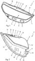
- the figure 1 illustrates a transparent element 1 intended to equip a lighting and / or signaling device for a motor vehicle.
- a lighting and / or signaling device for a motor vehicle.
- These include a vehicle front projector, also called lighthouse.
- the invention also finds a favorable application in a rear light for a motor vehicle, and in a general manner in any device intended to emit light.
- the lighting and / or signaling device consists of a rear housing that serves to support the various mechanical, electrical and light components embedded inside the housing. At least one light source generates a light beam to be projected on the road and this light source is installed in an internal volume of the lighting device and / or signaling delimited on one side by the housing, and on the other by the element at least partly transparent, hereinafter called transparent element 1. The light beam comes out therefore the lighting device and / or signaling through the transparent element 1. This element thus forms a closing mirror of the front projector.
- the figure 1 shows this transparent element 1 in a front view, that is to say by observing the element from outside the vehicle.
- This transparent element comprises two main portions, a first portion 2 of which is transparent to the light emitted by the light source and a second portion 3 is rendered, for example, opaque.
- the first portion 2 is a central portion of the transparent member while the second portion 3 is a peripheral band that surrounds the first portion 2.
- the second portion forms a flank adjacent to and surrounding the central portion. the latter.
- the second portion is rendered, for example, opaque so as to hide the components installed in the internal volume of the lighting and / or signaling device.
- the opaque or possibly colorized nature of the second portion also facilitates the marriage of the lighting and / or signaling device with the bodywork elements that surround it.
- the first portion 2 has an elongate shape and is thus surrounded at the top by a first longitudinal flank 5 constituting the second portion 3. Opposite this first flank 5 relative to the first portion 2, there is a second flank longitudinal 6. These two longitudinal flanks 5 and 6 are joined to each other by a first lateral blank 7 and a second lateral flank 8, installed opposite the first lateral flank 7 relative to the first portion 2.
- the transparent element 1 further comprises at least one fastening means 4 which contributes to the attachment of the lighting device and / or signaling on the vehicle that receives it.
- This fixing means 4 is, for example, installed at an angle between a longitudinal flank and a lateral flank, more particularly at the angle between the first longitudinal flank 5 and the first lateral flank 7.
- the transparent element 1 has an anti-shrinkage function, so called in that its main function is to counteract the removal of the transparent element 1 during the cooling of the first layer before injection of the second layer.
- Such an anti-shrink function is obtained by at least one first locking means 10 and at least one second locking means 11.
- Such locking means provide a retention of a first layer constituting the transparent element vis-à-vis the female cavity of a manufacturing mold of element 1.
- this first blocking means 10 and second blocking means 11 are respectively formed on either side of a plane, of longitudinal axis, which passes through the first portion 2.
- first locking means 10 are provided on the first longitudinal flank 5 while the second locking means 11 are formed on the second longitudinal flank 6.
- first locking means 10 and the second blocking means 11 are arranged on either side of the first portion 2. The specific forms of these locking means will be detailed at figures 2 and 3 .
- the figure 2 illustrates the structure of the transparent element 1 according to the invention.
- the latter comprises a first layer 12 made of a material transparent to the rays emitted by the light source installed in the lighting and / or signaling device, and a second layer 13 made of an opaque material, that is to say ie which prevents the passage of rays emitted by the light source.
- a first layer 12 made of a material transparent to the rays emitted by the light source installed in the lighting and / or signaling device
- a second layer 13 made of an opaque material, that is to say ie which prevents the passage of rays emitted by the light source.
- Such opacity may, for example, be achieved by means of a filler incorporated in the constituent material of the second layer 13. This opacity can also be obtained by applying a paint layer.
- the first layer 12 forms the major part of the transparent element 1 whereas the second layer 13 is arranged in particular zones of this element.
- the first portion 2 consists solely of the first layer 12. This first portion is therefore devoid of the second layer, because it is the portion of the transparent element to be traversed by the rays of the light source.
- the second portion 3 consists of a superposition of the first layer 12 and the second layer 13.
- the two layers are mechanically bonded to each other chemically.
- the material of the first layer 12 and the material of the second layer 13 are thus chemically compatible so as to mix with each other at least on a superficial thickness of each of the layers.
- this compatibility is obtained by using materials for the first layer 12 and the second layer 13 which are synthetic materials, in particular polymeric and optionally thermosetting.
- the material of the first layer is a polycarbonate.
- Such polycarbonate may also be used as a material for the second layer.
- the material of the first layer is a polymethylmethacrylate.
- the material of the second layer may also be a polymethylmethacrylate.
- the transparent element also comprises a border 14 made only by the second layer 13.
- a border 14 extends in particular in the extension of the first layer, at the longitudinal and lateral sides.
- the first blocking means 10 and the second blocking means 11 come from the first layer 12.
- it is the constituent material of the first layer 12 which is used to produce the particular forms of these locking means. This ensures that the mechanical strength related to the anti-shrinkage function is applied directly to the part that is to be maintained in position in the cavity of the mold, that is to say the first layer.
- the locking means is provided at the level of the second portion 3.
- the second locking means 11 which is formed at the level of the second longitudinal flank 6, by a conformation formed both in the first layer 12 and in the second layer 13.
- the first blocking means 10 is provided on the second portion 3, in particular at the level of the first longitudinal flank 5.
- the first blocking means is formed solely by the first layer 12.
- the second blocking means 11 is a bump deformation of the second portion 3.
- this deformation by embossing may have a rectangular or pyramidal shape which opens out from the second longitudinal flank 6 towards the outside of the vehicle, that is to say in a direction substantially identical to an optical axis of the light beam coming out of the lighting and / or signaling device.
- the second locking means takes the form of a hollow protuberance obtained by embossing, said protrusion being projecting from the opposite side to the side of the first layer on which the second layer is applied.
- the transparent element 1 may comprise a single and unique embossing deformation. According to the illustrated example, it can be seen that the transparent element comprises a second locking means 11 constituted by three distinct deformation by embossing distributed over the length of the second longitudinal flank 6.
- the second blocking means participates in the anti-removal function and also has at least one additional function.
- the deformation is able to ensure a mechanical holding of a part positioned on the transparent element 1.
- this deformation makes it possible to position a part so as to align it with the transparent element 1.
- This part is for example, an element of the vehicle body on which the transparent element is mounted. More specifically, it includes a shell or a bumper, for example before.
- At least one of the locking means takes the form of at least one hook formed on a peripheral edge 15 of the first layer 12, such a peripheral edge being the strip where the first layer 12 ends. In this case, it is is the first locking means 10 formed at the first longitudinal flank 5. The first locking means 10 is directly on the peripheral edge.
- the first blocking means 10 is continuous and unique along this peripheral edge 15, over at least a part of the length of the first longitudinal flank 5.
- the first blocking means 10 is discontinuous along the peripheral edge 15, which in practice makes it possible to form a multiplicity of hooks along this peripheral edge.
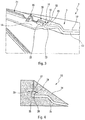
- the figure 3 shows in detail the first locking means 10.
- the superposition of the first layer 12 with the second layer 13 at the second portion 3 is particularly apparent, and it is found that the edge 14 made with the second layer 13 extends in forming a bevel, so as to fit into a complementary shape formed on the housing of the lighting and / or signaling device.
- the first locking means 10 forms a hook 16 by means of a hook bottom 17 which extends in a plane perpendicular to, or substantially perpendicular to, the plane in which the peripheral edge 15 extends.
- a return 18 originates from the hook bottom 17 and extends in a perpendicular plane, or substantially perpendicular to the extension plane of the hook base 17.
- the return 18 extends in a plane parallel to, or substantially parallel to, the plane of extension of the peripheral edge 15.
- Such a structure delimits a groove 19 which participates in the anti-removal function because it receives a rib which is formed on the female cavity of the manufacturing mold of the transparent element 1.
- the second layer 13 comprises a wafer 22 which is positioned against the hook bottom 17, which makes it possible to increase the mechanical strength between the first layer 12 and the second layer 13, at the peripheral edge 15, taking advantage of the existence of the hook.
- the figure 4 illustrates a tool for manufacturing, for example, a transparent element according to the invention.
- This is a mold 23 shown in section along a plane passing through the first blocking means of the transparent element.
- Such a mold 23 comprises a female cavity 24, a first male cavity 25 and a second male cavity (not shown).
- a first cavity 26 is formed between the first male cavity 25 and the female cavity 24 and this first cavity is filled by the transparent material constituting the first layer.
- a second cavity (not shown) formed between the first formed layer and the second male cavity is formed. The opaque material constituting the second layer is then injected against the first layer, so that these layers are superposed and chemically bonded to one another.
- the female cavity 24 comprises a closure plane 27 of the mold, this plane participating on one side in the delimitation of the first cavity 26, and the other being in contact with the first male cavity 25.
- This closure plane 27 surrounds the transparent element to be molded and comprises at least a first conformation 28 and a second conformation capable of blocking a withdrawal of the transparent element, in particular of the first layer of the transparent element.
- the first conformation 28 and the second conformation are formed on either side of an area of the mold or only the first layer is present, in particular on either side of a horizontal plane passing through this zone.
- the first conformation 28 has a shape complementary to the hook 16 detailed in FIG. figure 3 .
- the second conformation although not shown, has a shape complementary to a deformation using the second blocking means 11, shown on FIG. figure 2 .
- the first conformation 28 and / or the second conformation comprise a rib 29 adjacent to a groove 30, both formed in the plane of closing 27.
- the groove 30 forms the return 18 of the hook 16, while the rib 29 defines the hook bottom 17 of the first locking means.
- the element according to the invention is part of the constitution of a lighting and / or signaling device for motor vehicles.
Description
Le secteur technique de l'invention est, d'une façon générale, celui des éléments transparents qui ferment les dispositifs d'éclairage et/ou de signalisation, notamment les projecteurs avant ou arrière de véhicule automobile.The technical field of the invention is, in general, the transparent elements that close the lighting and / or signaling devices, including the front or rear headlights of a motor vehicle.
Il est connu de réaliser un élément transparent à partir de deux couches de matériaux injectés dans un moule. Un tel élément présente une forme galbée de manière à suivre les contours de la carrosserie du véhicule qu'il équipe. La fabrication est alors réalisée selon deux étapes, une première étape étant dédiée au moulage d'une première couche transparente par laquelle un flux lumineux passe pour éclairer la route empruntée par le véhicule. La deuxième étape consiste en une injection de la deuxième couche sur une zone spécifique de la première couche préalablement moulée.It is known to produce a transparent element from two layers of materials injected into a mold. Such an element has a curved shape so as to follow the contours of the body of the vehicle that it equips. The manufacturing is then carried out in two stages, a first stage being dedicated to the molding of a first transparent layer through which a luminous flux passes to illuminate the road taken by the vehicle. The second step consists of an injection of the second layer on a specific area of the first pre-molded layer.
Le moule comprend ainsi une empreinte femelle qui délimite le galbe concave de l'élément transparent et dans laquelle est insérée successivement une première empreinte mâle définissant la première couche, puis une deuxième empreinte mâle délimitant la deuxième couche. Un tel procédé implique le changement de la première empreinte mâle pour disposer la deuxième empreinte mâle.The mold thus comprises a female cavity which delimits the concave curve of the transparent element and in which is successively inserted a first male cavity defining the first layer, then a second male cavity delimiting the second layer. Such a method involves changing the first male footprint to arrange the second male footprint.
Cette phase de changement provoque un inconvénient majeur. En effet, pendant le temps nécessaire à la phase de changement d'empreintes mâles, la première couche de l'élément transparent refroidit et il se créé alors un retrait de la première couche par rapport à l'empreinte femelle. Un tel retrait se produit plus particulièrement dans un plan passant par le bord de la première couche en direction du bord opposé. Ce retrait est problématique car la deuxième empreinte mâle se trouve alors en interférence avec la première couche disposée dans l'empreinte femelle, ce qui génère des efforts mécaniques sur la première couche qui sont de nature à l'endommager, en créant par exemple des rayures.This phase of change causes a major disadvantage. Indeed, during the time required for the male fingerprint change phase, the first layer of the transparent element cools and it is then created a withdrawal of the first layer relative to the female cavity. Such removal occurs more particularly in a plane passing through the edge of the first layer towards the opposite edge. This removal is problematic because the second male cavity is then in interference with the first layer disposed in the female cavity, which generates mechanical forces on the first layer which are likely to damage it, creating for example scratches .
Par ailleurs, ce retrait de la première couche permet au matériau de la deuxième couche de s'infiltrer dans des zones non souhaitées, ce qui se traduit par une mise au rebut de l'élément transparent une fois terminé.Furthermore, this removal of the first layer allows the material of the second layer to infiltrate undesired areas, which results in a disposal of the transparent element once completed.
Un des buts de la présente invention est donc de résoudre l'inconvénient décrit ci-dessus.One of the aims of the present invention is therefore to solve the disadvantage described above.
Selon un principe de l'invention, ce but est résolu principalement en maintenant le bord de la première couche dans l'empreinte femelle de manière à ce que celui-ci ne puisse pas s'écarter de cette empreinte femelle pendant la phase de changement d'empreinte mâle..According to a principle of the invention, this object is solved mainly by keeping the edge of the first layer in the female cavity so that it can not deviate from this female cavity during the change phase. male imprint ..
Il est ainsi connu de
L'élément transparent bicouche décrit dans ce document présente une face parfaitement plane et la deuxième couche est injectée sur la partie extérieure visible : le raccord de jonction entre la première et la deuxième couche est donc visible de l'extérieur et la face externe n'est pas d'une seule pièce continue. La languette périphérique permet l'emboitement de l'élément dans une rainure aménagée sur un boitier renfermant des sources lumineuses afin de constituer un dispositif d'éclairage.The bilayer transparent element described in this document has a perfectly flat face and the second layer is injected on the visible outer part: the junction connection between the first and the second layer is visible from the outside and the outer face n ' is not one piece continuous. The peripheral tongue allows the fitting of the element in a groove on a housing enclosing light sources to form a lighting device.
On comprend bien que cette solution nécessite une quantité de matière non négligeable pour former la languette et qu'en outre elle est difficilement adaptable à des formes d'élément tridimensionnellement plus complexes, notamment non globalement planes, la languette étant alors susceptible de ne pas assurer un maintien efficace de la première couche dans l'empreinte femelle pendant la phase de retrait. Enfin, cette solution confère un aspect peu esthétique aux dispositifs de signalisation incorporant de tels éléments bicouche, alors qu'aujourd'hui l'aspect esthétique extérieur de ces dispositifs est devenu primordial.It will be understood that this solution requires a quantity of material that is not negligible to form the tongue and that, moreover, it is difficult to adapt to three-dimensionally more complex element shapes, in particular not being generally planar, the tongue then being capable of not ensuring effective maintenance of the first layer in the female cavity during the withdrawal phase. Finally, this solution confers an unattractive appearance to the signaling devices incorporating such bilayer elements, while today the external aesthetic appearance of these devices has become paramount.
L'invention vise donc à proposer une solution de fonction anti-retrait qui nécessite peu de matière supplémentaire tout en assurant une plus grande liberté de conception dans la forme de l'élément et qui procure un meilleur aspect esthétique.The object of the invention is therefore to propose an anti-withdrawal function solution which requires little additional material while ensuring a greater freedom of design in the shape of the element and which gives a better aesthetic appearance.
A cet égard, l'invention a pour objet un élément au moins en partie transparent pour un dispositif d'éclairage et/ou de signalisation d'un véhicule, réalisé avec une première couche et au moins une deuxième couche, ledit élément comprenant une première portion dépourvue de la deuxième couche et une deuxième portion où la première couche et la deuxième couche se superposent, caractérisé en que l'élément comprend un premier moyen de blocage de la première couche et un deuxième moyen de blocage de la première couche disposés de part et d'autre de la première portion, le premier moyen de blocage prenant la forme d'au moins un crochet directement ménagé sur un bord périphérique de la première couche et le deuxième moyen de blocage est formé par au moins une déformation par bosselage de la deuxième portion.In this respect, the subject of the invention is an element at least partly transparent for a lighting and / or signaling device of a vehicle, made with a first layer and at least a second layer, said element comprising a first portion devoid of the second layer and a second portion where the first layer and the second layer are superimposed, characterized in that the element comprises a first blocking means of the first layer and a second blocking means of the first layer arranged from and other of the first portion, the first locking means in the form of at least one hook directly formed on a peripheral edge of the first layer and the second locking means is formed by at least one bent deformation of the second portion.
Cette répartition des moyens de blocage est, par exemple, réalisée de part et d'autre d'un plan passant par la longueur de la première portion.This distribution of the blocking means is, for example, carried out on either side of a plane passing through the length of the first portion.
On comprend bien que cette combinaison de deux moyens de blocage de forme différente permet d'assurer le blocage du retrait quelle que soit la géométrie de la pièce, avec peu de matière additionnelle et permet en outre d'utiliser avantageusement ces moyens de blocage pour des fonctions additionnelles d'assemblage et de fixation.It is well understood that this combination of two differently shaped locking means makes it possible to ensure the locking of the shrinkage regardless of the geometry of the part, with little additional material and also makes it possible to advantageously use these locking means for additional functions of assembly and fixing.
Selon une première caractéristique, le premier moyen de blocage et le deuxième moyen de blocage sont issus de la première couche. En d'autres termes, c'est le matériau utilisé pour fabriquer la première couche qui forme également le premier et le deuxième moyen de blocage.According to a first characteristic, the first blocking means and the second blocking means are derived from the first layer. In other words, it is the material used to make the first layer which also forms the first and second blocking means.
Au moins un des moyens de blocage est ménagé au niveau de la deuxième portion. Selon une réalisation de l'invention, les deux moyens de blocage sont formés au niveau de la deuxième portion. Cette dernière étant notamment opaque et au moins en partie cachée par un ou des éléments de carrosserie, on garantit ainsi que les formes particulières des moyens de blocage sont invisibles pour un utilisateur placé devant le dispositif d'éclairage et/ou de signalisation installé sur le véhicule.At least one of the locking means is provided at the second portion. According to one embodiment of the invention, the two locking means are formed at the second portion. The latter being particularly opaque and at least partly hidden by one or more bodywork elements, it is guaranteed and the particular forms of the locking means are invisible to a user placed in front of the lighting and / or signaling device installed on the vehicle.
Selon une réalisation de l'invention, l'élément au moins en partie transparent selon l'invention est une glace de fermeture d'un dispositif d'éclairage et/ou de signalisation. Le dispositif d'éclairage et/ou de signalisation peut, par exemple, être un projecteur. Selon un exemple de réalisation, la deuxième portion forme le pied de la glace de fermeture ; ce pied est la partie destinée à passer sous la carrosserie du véhicule sur lequel le dispositif d'éclairage et/ou de signalisation est destiné à être monté.According to one embodiment of the invention, the at least partly transparent element according to the invention is a closing lens of a lighting and / or signaling device. The lighting and / or signaling device may, for example, be a projector. According to an exemplary embodiment, the second portion forms the foot of the closure glass; this foot is the part intended to pass under the body of the vehicle on which the lighting and / or signaling device is intended to be mounted.
Selon un mode de réalisation, le premier moyen de blocage prend la forme d'au moins un crochet ménagé directement sur un bord périphérique de la première couche. Cette zone particulière de la première couche se prête facilement à la formation du crochet puisqu'il s'agit de l'extrémité de la première couche.According to one embodiment, the first locking means takes the form of at least one hook formed directly on a peripheral edge of the first layer. This particular zone of the first layer lends itself easily to the formation of the hook since it is the end of the first layer.
Selon une variante, le premier moyen de blocage est discontinu de manière à former une multiplicité de crochets le long du bord périphérique. Cette solution permet de former les crochets en des endroits discrets et limite la consommation de matière supplémentaire pour réaliser la fonction anti-retrait.According to one variant, the first blocking means is discontinuous so as to form a multiplicity of hooks along the peripheral edge. This solution makes it possible to form the hooks in discrete places and limits the consumption of additional material to perform the anti-removal function.
En outre, cette réalisation du premier moyen de blocage sous la forme d'un ou plusieurs crochets lui confère avantageusement une fonction additionnelle à la fonction anti-retrait, à savoir une fonction d'assemblage et de maintien par encliquetage pour le montage de l'élément sur un boitier d'un dispositif d'éclairage ou de signalisation.In addition, this embodiment of the first blocking means in the form of one or more hooks advantageously gives it an additional function to the anti-removal function, namely a snap fit and hold function for mounting the element on a case of a lighting or signaling device.
Le premier moyen de blocage est formé par le ou les crochets et le deuxième moyen de blocage est formé par au moins une déformation par bosselage de la deuxième portion. Un tel bosselage est en outre apte à assurer un maintien mécanique d'une pièce positionnée sur l'élément transparent, notamment une pièce de carrosserie du véhicule équipé de l'élément selon l'invention. Le positionnement, la fixation et le maintien d'un dispositif d'éclairage comprenant l'élément selon l'invention est ainsi facilité.The first blocking means is formed by the hook or hooks and the second blocking means is formed by at least one embossing deformation of the second portion. Such a bump is also able to ensure a mechanical support of a workpiece positioned on the transparent element, in particular a bodywork part of the vehicle equipped with the element according to the invention. Positioning, fixing and maintaining a lighting device comprising the element according to the invention is thus facilitated.
Selon une réalisation de l'invention, le ou les crochets sont formés uniquement d'un côté de la première portion. Le premier moyen de blocage est ainsi formé uniquement sur un premier flanc longitudinal de l'élément alors que le deuxième moyen de blocage est formé uniquement sur un deuxième flanc longitudinal de l'élément, opposé au premier flanc longitudinal par rapport à la première portion transparente.According to one embodiment of the invention, the hook or hooks are formed only on one side of the first portion. The first locking means is thus formed only on a first longitudinal flank of the element while the second locking means is formed only on a second longitudinal flank of the element, opposite to the first longitudinal flank with respect to the first transparent portion .
Le crochet délimite une gorge apte à recevoir une nervure ménagée sur un moule de fabrication de l'élément.The hook defines a groove adapted to receive a rib formed on a mold for manufacturing the element.
Selon une solution particulière, la première portion est centrale alors que la deuxième portion est à la périphérie de la première portion. C'est donc bien la portion centrale qui est apte à être traversée par les rayons émis par une source lumineuse embarquée dans le dispositif d'éclairage et/ou de signalisation. La deuxième portion est ainsi délimitée par une bande qui chemine le long du bord de la première couche.According to a particular solution, the first portion is central while the second portion is at the periphery of the first portion. It is therefore the central portion which is able to be traversed by the rays emitted by a light source embedded in the lighting and / or signaling device. The second portion is thus delimited by a strip which travels along the edge of the first layer.
On notera tout particulièrement que la première couche est transparente alors que la deuxième couche est opaque. Par transparente, on entend apte à être traversée par le faisceau lumineux généré par la source lumineuse sans altérer significativement ce dernier. Par opaque, on entend la faculté de rendre invisible à l'oeil humain les rayons qui sont émis par la source lumineuse en direction de la deuxième portion.It will be particularly noted that the first layer is transparent while the second layer is opaque. Transparency is understood to be able to be traversed by the light beam generated by the light source without significantly altering the latter. Opaque means the ability to render invisible to the human eye the rays that are emitted by the light source towards the second portion.
On notera encore que la première couche et la deuxième couche sont réalisées en un matériau synthétique. Il importe que le ou les matériaux employés pour les couches soient chimiquement compatibles, de manière à garantir un lien mécanique au niveau de la deuxième portion. Selon un exemple, la première couche et/ou la deuxième couche sont en polycarbonate. Elles peuvent également être en polyméthacrylate de méthyle. Enfin, l'une des couches peut être en polycarbonate alors que l'autre couche est en polyméthacrylate de méthyle.It will be noted that the first layer and the second layer are made of a synthetic material. It is important that the material or materials used for the layers are chemically compatible, so as to ensure a mechanical link in the second portion. In one example, the first layer and / or the second layer are made of polycarbonate. They can also be polymethyl methacrylate. Finally, one of the layers may be polycarbonate while the other layer is polymethyl methacrylate.
Selon une réalisation de l'invention, l'élément au moins en partie transparent selon l'invention est une glace de fermeture d'un dispositif d'éclairage et/ou de signalisation. Le dispositif d'éclairage et/ou de signalisation peut, par exemple, être un projecteur.According to one embodiment of the invention, the at least partly transparent element according to the invention is a closing lens of a lighting and / or signaling device. The lighting and / or signaling device may, for example, be a projector.
L'invention vise également un dispositif d'éclairage et/ou de signalisation comprenant l'élément au moins en partie transparent selon l'invention.The invention also relates to a lighting and / or signaling device comprising the element at least partly transparent according to the invention.
L'invention vise également un moule de fabrication, par exemple d'un élément au moins en partie transparent destiné à intégrer un dispositif d'éclairage et/ou de signalisation d'un véhicule, comprenant une empreinte femelle et deux empreintes mâles, une première cavité étant formée entre l'empreinte femelle et une première empreinte mâle pour réaliser une première couche de l'élément transparent, une deuxième cavité étant formée entre la première couche préalablement formée et une deuxième empreinte mâle pour réaliser une deuxième couche de l'élément transparent, caractérisé en ce que l'empreinte femelle comprend au moins une première conformation et une deuxième conformation aptes à bloquer un retrait de la première couche de l'élément.The invention also relates to a manufacturing mold, for example an at least partly transparent element intended to integrate a lighting and / or signaling device of a vehicle, comprising a female cavity and two male footprints, a first cavity being formed between the female cavity and a first male cavity to provide a first layer of the transparent element, a second cavity being formed between the first layer previously formed and a second male cavity to provide a second layer of the transparent element , characterized in that the female cavity comprises at least a first conformation and a second conformation able to block a withdrawal of the first layer of the element.
Dans un tel moule, au moins une des conformations comprend une nervure adjacente à une rainure, toutes deux formées dans un plan de fermeture de l'empreinte femelle.In such a mold, at least one of the conformations comprises a rib adjacent to a groove, both formed in a plane of closure of the female cavity.
Le moule selon l'invention peut être utilisé pour réaliser l'élément au moins en partie transparent selon l'invention.The mold according to the invention can be used to produce the element at least partly transparent according to the invention.
Un tout premier avantage selon l'invention réside dans la possibilité de maintenir le bord de la première couche contre l'empreinte femelle, en une position qui garantit l'absence d'interférence mécanique entre la première couche et la deuxième empreinte mâle. Cette solution est avantageuse car elle est simple à mettre en oeuvre et ne génère pas de difficulté pour démouler l'élément selon l'invention quand le moulage est terminé.A first advantage of the invention lies in the ability to maintain the edge of the first layer against the female cavity, in a position that ensures the absence of mechanical interference between the first layer and the second male cavity. This solution is advantageous because it is simple to implement and does not generate any difficulty in demolding the element according to the invention when the molding is finished.
-
D'autres caractéristiques, détails et avantages de l'invention ressortiront plus clairement à la lecture de la description donnée ci-après à titre indicatif en relation avec des dessins dans lesquels :
- la
figure 1 est une vue en perspective de face d'un élément selon l'invention, - la
figure 2 est une vue en perspective coupée illustrant l'élément selon l'invention, - la
figure 3 est une vue en perspective qui montre le détail des moyens de réalisation de la fonction anti-retrait équipant un élément selon l'invention, et - la
figure 4 est une vue en coupe partielle d'un moule avec lequel peut être fabriqué l'élément selon l'invention.
- the
figure 1 is a front perspective view of an element according to the invention, - the
figure 2 is a cut perspective view illustrating the element according to the invention, - the
figure 3 is a perspective view which shows the detail of the means of realization of the anti-removal function equipping an element according to the invention, and - the
figure 4 is a partial sectional view of a mold with which the element according to the invention can be manufactured.
- la
Il faut noter que les figures exposent l'invention de manière détaillée pour mettre en oeuvre l'invention, lesdites figures pouvant bien entendu servir à mieux définir l'invention le cas échéant.It should be noted that the figures disclose the invention in detail to implement the invention, said figures can of course be used to better define the invention where appropriate.
La
Le dispositif d'éclairage et/ou de signalisation est constitué d'un boîtier arrière qui sert de support aux différents composants mécaniques, électriques et lumineux embarqués à l'intérieur du boîtier. Au moins une source de lumière génère un faisceau lumineux à projeter sur la route et cette source lumineuse est installée dans un volume interne du dispositif d'éclairage et/ou de signalisation délimité, d'un côté par le boîtier, et de l'autre par l'élément au moins en partie transparent, ci-après appelé élément transparent 1. Le faisceau lumineux sort donc du dispositif d'éclairage et/ou de signalisation en traversant l'élément transparent 1. Cet élément forme ainsi une glace de fermeture du projecteur avant.The lighting and / or signaling device consists of a rear housing that serves to support the various mechanical, electrical and light components embedded inside the housing. At least one light source generates a light beam to be projected on the road and this light source is installed in an internal volume of the lighting device and / or signaling delimited on one side by the housing, and on the other by the element at least partly transparent, hereinafter called
La
La deuxième portion est rendue, par exemple, opaque de manière à cacher les composants installés dans le volume interne du dispositif d'éclairage et/ou de signalisation. Le caractère opaque, ou éventuellement colorisé, de la deuxième portion facilite également le mariage du dispositif d'éclairage et/ou de signalisation avec les éléments de carrosserie qui l'entoure.The second portion is rendered, for example, opaque so as to hide the components installed in the internal volume of the lighting and / or signaling device. The opaque or possibly colorized nature of the second portion also facilitates the marriage of the lighting and / or signaling device with the bodywork elements that surround it.
La première portion 2 présente une forme allongée et se trouve ainsi entourée au dessus par un premier flanc longitudinal 5 constitutif de la deuxième portion 3. A l'opposé de ce premier flanc 5 par rapport à la première portion 2, on trouve un deuxième flanc longitudinale 6. Ces deux flancs longitudinaux 5 et 6 sont joints l'un à l'autre par un premier flan latéral 7 et un deuxième flanc latéral 8, installé à l'opposé du premier flanc latéral 7 par rapport à la première portion 2. L'élément transparent 1 comprend encore au moins un moyen de fixation 4 qui participe à la solidarisation du dispositif d'éclairage et/ou de signalisation sur le véhicule que le reçoit. Ce moyen de fixation 4 est, par exemple, installé à un angle entre un flanc longitudinal et un flanc latéral, plus particulièrement à l'angle situé entre le premier flanc longitudinal 5 et le premier flan latéral 7.The
L'élément transparent 1 présente une fonction anti-retrait , appelée ainsi en ce sens que sa fonction principale est de contrecarrer le retrait de l'élément transparent 1 pendant le refroidissement de la première couche avant injection de la deuxième couche. Une telle fonction anti-retrait est obtenue par au moins un premier moyen de blocage 10 et au moins un deuxième moyen de blocage 11. De tels moyens de blocage assurent une retenue d'une première couche constitutive de l'élément transparent vis-à-vis de l'empreinte femelle d'un moule de fabrication de l'élément 1.The
Selon une réalisation de l'invention, ce premier moyen de blocage 10 et ce deuxième moyen de blocage 11 sont respectivement ménagés de part et d'autre d'un plan, d'axe longitudinal, qui passe par la première portion 2. En référence au
La
La première couche 12 forme la majeure partie de l'élément transparent 1 alors que la deuxième couche 13 est disposée en des zones particulières de cet élément. Ainsi, la première portion 2 est uniquement constituée de la première couche 12. Cette première portion est donc dépourvue de la deuxième couche, en raison du fait qu'il s'agit de la portion de l'élément transparent destinée à être traversée par les rayons de la source lumineuse. La deuxième portion 3 est quant à elle constituée d'une superposition de la première couche 12 et de la deuxième couche 13.The
Dans cette deuxième portion 3, les deux couches sont liées mécaniquement l'une à l'autre chimiquement. Le matériau de la première couche 12 et le matériau de la deuxième couche 13 sont ainsi chimiquement compatibles de manière à se mélanger l'un à l'autre au moins sur une épaisseur superficielle de chacune des couches. De manière avantageuse, cette compatibilité est obtenue en employant des matériaux pour la première couche 12 et pour la deuxième couche 13 qui sont des matières synthétiques, notamment polymériques et éventuellement thermodurcissables.In this
A titre d'exemple, le matériau de la première couche est un polycarbonate. Un tel polycarbonate peut également être utilisé comme matériau pour la deuxième couche.For example, the material of the first layer is a polycarbonate. Such polycarbonate may also be used as a material for the second layer.
De manière alternative ou complémentaire, le matériau de la première couche est un polyméthacrylate de méthyle. Le matériau de la deuxième couche peut également être un polyméthacrylate de méthyle.Alternatively or additionally, the material of the first layer is a polymethylmethacrylate. The material of the second layer may also be a polymethylmethacrylate.
L'élément transparent comprend encore une bordure 14 réalisée uniquement par la deuxième couche 13. Une telle bordure 14 s'étend notamment dans le prolongement de la première couche, au niveau des flancs longitudinaux et latéraux.The transparent element also comprises a
Selon un exemple de réalisation préférée, le premier moyen de blocage 10 et le deuxième moyen de blocage 11 sont issus de la première couche 12. En d'autres termes, c'est le matériau constitutif de la première couche 12 qui est employé pour réaliser les formes particulières de ces moyens de blocage. On garantit ainsi que la tenue mécanique liée à la fonction anti-retrait est appliquée directement à la pièce que l'on souhaite maintenir en position dans l'empreinte du moule, c'est-à-dire la première couche.According to a preferred embodiment, the first blocking means 10 and the second blocking means 11 come from the
On notera qu'au moins un des moyens de blocage est ménagé au niveau de la deuxième portion 3. Dans le cas exemplatif de la
Le deuxième moyen de blocage 11 est une déformation par bosselage de la deuxième portion 3. Selon l'exemple de réalisation illustré aux
L'élément transparent 1 peut comprendre une seule et unique déformation par bosselage. Selon l'exemple illustré, on constate que l'élément transparent comprend un deuxième moyen de blocage 11 constitué de trois déformations par bosselage distinctes, réparties sur la longueur du deuxième flanc longitudinal 6.The
Le deuxième moyen de blocage participe à la fonction d'anti-retrait et présente en outre au moins une fonction supplémentaire. En effet, la déformation est apte à assurer un maintien mécanique d'une pièce positionnée sur l'élément transparent 1. Autrement dit, cette déformation permet de positionner une pièce de manière à l'aligner sur l'élément transparent 1. Cette pièce est, par exemple, un élément de la carrosserie du véhicule sur lequel l'élément transparent est monté. De manière plus précise, il s'agit notamment d'une calandre ou d'un pare-choc, par exemple avant.The second blocking means participates in the anti-removal function and also has at least one additional function. Indeed, the deformation is able to ensure a mechanical holding of a part positioned on the
Au moins un des moyens de blocage prend la forme d'au moins un crochet ménagé sur un bord périphérique 15 de la première couche 12, un tel bord périphérique étant la bande où se termine la première couche 12. Dans le cas présent, il s'agit du premier moyen de blocage 10 formé au niveau du premier flanc longitudinal 5. Le premier moyen de blocage 10 est directement ménagé sur le bord périphérique.At least one of the locking means takes the form of at least one hook formed on a
Selon un exemple de réalisation, le premier moyen de blocage 10 est continu et unique le long de ce bord périphérique 15, sur au moins une partie de la longueur du premier flanc longitudinal 5. De manière alternative, le premier moyen de blocage 10 est discontinu le long du bord périphérique 15, ce qui, en pratique, permet de former une multiplicité de crochets le long de ce bord périphérique.According to an exemplary embodiment, the first blocking means 10 is continuous and unique along this
La
Le premier moyen de blocage 10 forme un crochet 16 au moyen d'un fond de crochet 17 qui s'étend dans un plan perpendiculaire, ou sensiblement perpendiculaire, au plan dans lequel s'étend le bord périphérique 15. Un retour 18 prend naissance sur le fond de crochet 17 et s'étend dans un plan perpendiculaire, ou sensiblement perpendiculaire, au plan d'extension du fond de crochet 17. Ainsi, le retour 18 s'étend dans un plan parallèle, ou sensiblement parallèle, au plan d'extension du bord périphérique 15. Une telle structure permet de délimiter une gorge 19 qui participe à la fonction d'anti-retrait car elle reçoit une nervure qui est ménagée sur l'empreinte femelle du moule de fabrication de l'élément transparent 1.The first locking means 10 forms a
Le long du bord périphérique 15, on constate la présence d'excroissances référencées 20 et 21, de telles excroissances ayant pour fonction de renforcer la tenue mécanique entre la première couche 12 et la deuxième couche 13, au niveau du bord périphérique 15. Ces excroissances 20 et 21 sont constituées de la première couche 12 et de la deuxième couche 13 et débouchent du bord périphérique 15, selon une direction sensiblement perpendiculaire. On constate enfin que la deuxième couche 13 comprend une tranche 22 qui est positionnée contre le fond de crochet 17, ce qui permet d'augmenter la tenue mécanique entre la première couche 12 et la deuxième couche 13, au niveau du bord périphérique 15, en mettant à profit l'existence du crochet.Along the
La
Un tel moule 23 comprend une empreinte femelle 24, une première empreinte mâle 25 et une deuxième empreinte mâle (non représenté). Une première cavité 26 est ménagée entre la première empreinte mâle 25 et l'empreinte femelle 24 et cette première cavité est remplie par le matériau transparent constitutif de la première couche. Postérieurement à la formation de la première couche, il est réalisé une deuxième cavité (non représentée) formée entre la première couche préalablement formée et la deuxième empreinte mâle. On injecte alors le matériau opaque constitutif de la deuxième couche contre la première couche, de manière à ce que ces couches se superposent et lient chimiquement l'une à l'autre.Such a mold 23 comprises a
L'empreinte femelle 24 comprend un plan de fermeture 27 du moule, ce plan participant d'un côté à la délimitation de la première cavité 26, et de l'autre étant en contact contre la première empreinte mâle 25. Ce plan de fermeture 27 entoure l'élément transparent à mouler et comprend au moins une première conformation 28 et une deuxième conformation aptes à bloquer un retrait de l'élément transparent, notamment de la première couche de l'élément transparent. La première conformation 28 et la deuxième conformation sont ménagées de part et d'autre d'une zone du moule ou seule la première couche est présente, notamment de part et d'autre d'un plan horizontal passant par cette zone.The
La première conformation 28 présente une forme complémentaire au crochet 16 détaillé à la
La première conformation 28 et/ou la deuxième conformation comprennent une nervure 29 adjacente à une rainure 30, toutes deux formées dans le plan de fermeture 27. La rainure 30 permet de former le retour 18 du crochet 16, alors que la nervure 29 délimite le fond de crochet 17 du premier moyen de blocage.The
Une fois que la première couche se solidifie dans la première cavité 26, un maintien mécanique s'opère entre cette première couche et l'empreinte femelle 24 de part et d'autre de la première portion de l'élément transparent. Un déplacement de la première couche selon une direction parallèle au fond de crochet est alors interdit et l'insertion de la deuxième empreinte mâle ne risque pas d'endommager la première couche.Once the first layer solidifies in the
L'élément selon l'invention entre dans la constitution de dispositif d'éclairage et/ou de signalisation de véhicules automobiles.The element according to the invention is part of the constitution of a lighting and / or signaling device for motor vehicles.
Claims (11)
- At least partially transparent element (1) for a lighting and/or signalling device of a vehicle, produced with a first layer (12) and at least one second layer (13), said element (1) comprising a first portion (2) without the second layer (13) and a second portion (3) in which the first layer (12) and the second layer (13) are superposed, the element (1) comprising a first locking means (10) for the first layer (12) and a second locking means (11) for the first layer (12) that are disposed on either side of the first portion (2), characterized in that the first locking means (10) is in the form of at least one clip (16) formed directly on a peripheral edge (15) of the first layer (12), and in that the second locking means (11) is formed by a deformation by embossing the second portion (3).
- Element according to Claim 1, the first locking means (10) and the second locking means (11) are part of the first layer (12).
- Element according to either one of the preceding claims, wherein the first locking means (10) is discontinuous so as to form a multiplicity of clips (16) along the peripheral edge (15).
- Element according to any one of the preceding claims, wherein the at least one clip (16) is formed only on one side of the first portion (2).
- Element according to any one of the preceding claims, wherein the clip (16) delimits a groove (19) that is able to receive a rib (29) formed on a mould for manufacturing the element (1).
- Element according to any one of the preceding claims, wherein the first portion (2) is central while the second portion (3) is at the periphery of the first portion (2).
- Element according to any one of the preceding claims, wherein the first layer (12) is transparent while the second layer (13) is opaque.
- Element according to any one of the preceding claims, wherein the first layer (12) and the second layer (13) are produced from a plastics material.
- Element according to any one of the preceding claims, wherein the first layer (12) and/or the second layer (13) are made of polycarbonate.
- Element according to any one of the preceding claims, wherein at least the first layer (12) and/or the second layer (13) are made of polymethyl methacrylate.
- Lighting and/or signalling device comprising an at least partially transparent element according to one of the preceding claims.
Applications Claiming Priority (1)
| Application Number | Priority Date | Filing Date | Title |
|---|---|---|---|
| FR1253287A FR2989449B1 (en) | 2012-04-11 | 2012-04-11 | TRANSPARENT ELEMENT FOR A VEHICLE LIGHTING AND / OR SIGNALING DEVICE, COMPRISING AN ANTI-WITHDRAWAL MEANS, AND A MOLD FOR THE PRODUCTION OF SUCH AN ELEMENT |
Publications (2)
| Publication Number | Publication Date |
|---|---|
| EP2650098A1 EP2650098A1 (en) | 2013-10-16 |
| EP2650098B1 true EP2650098B1 (en) | 2018-10-10 |
Family
ID=48045375
Family Applications (1)
| Application Number | Title | Priority Date | Filing Date |
|---|---|---|---|
| EP13163389.3A Active EP2650098B1 (en) | 2012-04-11 | 2013-04-11 | Transparent element for a lighting and/or signalling device |
Country Status (2)
| Country | Link |
|---|---|
| EP (1) | EP2650098B1 (en) |
| FR (1) | FR2989449B1 (en) |
Cited By (2)
| Publication number | Priority date | Publication date | Assignee | Title |
|---|---|---|---|---|
| FR3121734A1 (en) * | 2021-04-13 | 2022-10-14 | Psa Automobiles Sa | OPTICAL UNIT WITH REINFORCED EXTERNAL RIB FOR SIDE SUPPORT OF A LAND VEHICLE BUMPER |
| FR3127036A1 (en) * | 2021-09-16 | 2023-03-17 | Psa Automobiles Sa | Motor vehicle lighting and/or signaling device. |
Families Citing this family (8)
| Publication number | Priority date | Publication date | Assignee | Title |
|---|---|---|---|---|
| FR3026339B1 (en) * | 2014-09-30 | 2017-04-21 | Valeo Vision | MOLD FOR THE MANUFACTURE OF A POLYMER ELEMENT FOR AN OPTICAL BLOCK FOR A MOTOR VEHICLE HAVING A COUPLING MEMBER |
| DE102016102982A1 (en) | 2015-03-03 | 2016-09-08 | Inglass S.P.A. | Process for the preparation of a component |
| FR3037380B1 (en) * | 2015-06-12 | 2020-01-17 | Valeo Vision | ICE FOR LIGHTING DEVICE AND ITS MANUFACTURING METHOD |
| JP7036612B2 (en) * | 2018-02-13 | 2022-03-15 | 株式会社小糸製作所 | Resin molded product |
| FR3102395B1 (en) * | 2019-10-25 | 2023-04-14 | Psa Automobiles Sa | Headlamp lens for a motor vehicle and injection mold intended for the production of said lens |
| FR3115003B1 (en) * | 2020-10-09 | 2022-12-30 | Psa Automobiles Sa | DOUBLE WINDOW HEADLIGHT AND VEHICLE COMPRISING SUCH HEADLIGHT |
| DE102021117738A1 (en) * | 2021-07-09 | 2023-01-12 | Bayerische Motoren Werke Aktiengesellschaft | Headlight device for a tilting vehicle and tilting vehicle with such a headlight device |
| CN114131849A (en) * | 2021-12-22 | 2022-03-04 | 东莞市百优精密模具塑胶有限公司 | Injection mold of headlamp frame |
Citations (4)
| Publication number | Priority date | Publication date | Assignee | Title |
|---|---|---|---|---|
| DE4011642C1 (en) | 1990-04-11 | 1991-05-23 | Hella Kg Hueck & Co, 4780 Lippstadt, De | Vehicle headlamp with housing of plastics material - with U=shaped locating groove facing forward to accept sealing ring |
| DE4417404A1 (en) | 1993-05-18 | 1994-11-24 | Koito Mfg Co Ltd | Layered lens, made from a synthetic resin, for a vehicle illumination device (car lighting device), method and device for shaping said lens |
| DE19858183C1 (en) | 1998-12-17 | 2000-07-13 | Otto Gruenhagel | Method and device for the injection molding of one, two or multi-colored plastic parts |
| WO2008068253A1 (en) | 2006-12-05 | 2008-06-12 | Renault S.A.S. | Arrangement of support means for a motor vehicle bumper |
Family Cites Families (4)
| Publication number | Priority date | Publication date | Assignee | Title |
|---|---|---|---|---|
| FR2708334B1 (en) * | 1993-07-01 | 1995-10-20 | Valeo Vision | Element of style or optics, of shiny appearance and neutral tint, for lighting or automotive signaling. |
| JP2925128B2 (en) * | 1993-12-07 | 1999-07-28 | 本田技研工業株式会社 | Resin mold |
| FR2733175B1 (en) * | 1995-04-21 | 1997-07-04 | Valeo Vision | METHOD AND MOLD FOR THE INJECTION MOLDING OF A GLASS OF A LIGHTING OR SIGNALING DEVICE OF A MOTOR VEHICLE |
| JP3409645B2 (en) * | 1997-05-26 | 2003-05-26 | 豊田合成株式会社 | Two-color molding method |
-
2012
- 2012-04-11 FR FR1253287A patent/FR2989449B1/en active Active
-
2013
- 2013-04-11 EP EP13163389.3A patent/EP2650098B1/en active Active
Patent Citations (4)
| Publication number | Priority date | Publication date | Assignee | Title |
|---|---|---|---|---|
| DE4011642C1 (en) | 1990-04-11 | 1991-05-23 | Hella Kg Hueck & Co, 4780 Lippstadt, De | Vehicle headlamp with housing of plastics material - with U=shaped locating groove facing forward to accept sealing ring |
| DE4417404A1 (en) | 1993-05-18 | 1994-11-24 | Koito Mfg Co Ltd | Layered lens, made from a synthetic resin, for a vehicle illumination device (car lighting device), method and device for shaping said lens |
| DE19858183C1 (en) | 1998-12-17 | 2000-07-13 | Otto Gruenhagel | Method and device for the injection molding of one, two or multi-colored plastic parts |
| WO2008068253A1 (en) | 2006-12-05 | 2008-06-12 | Renault S.A.S. | Arrangement of support means for a motor vehicle bumper |
Non-Patent Citations (8)
| Title |
|---|
| ANONYMOUS: "LA Auto Show", 25 January 2019 (2019-01-25), pages 1 - 41, XP055628644, Retrieved from the Internet <URL:https://en.wikipedia.org/w/index.php?title=LA_Auto_Show&oldid=880170929> |
| ANONYMOUS: "Mehr Passat als Phaeton", AUTOBILD FAHRBERICHT, 16 January 2012 (2012-01-16), XP055628637, Retrieved from the Internet <URL:https://www.autobild.de/artikel/vw-cc-fahrbericht-2793747.html> |
| ANONYMOUS: "Mercedes zeigt das neue B", AUTOBILD IAA, 25 August 2011 (2011-08-25), XP055628647, Retrieved from the Internet <URL:https://www.autobild.de/artikel/mercedes-b-klasse-iaa-2011-1884665.html> |
| ANONYMOUS: "Mercedes-Benz W 242/W 246 - Wikipedia", 4 June 2019 (2019-06-04), XP055628650, Retrieved from the Internet <URL:https://de.wikipedia.org/w/index.php?title=Mercedes-Benz_W_242/W_246&oldid=189260179> |
| ANONYMOUS: "Schwindung – Lexikon der Kunststoffprüfung", 2018022016, pages 1 - 5, XP055628629, Retrieved from the Internet <URL:http://wiki.polymerservice-merseburg.de/index.php?title=Schwindung&oldid=7381> |
| ANONYMOUS: "VW CC – Wikipedia", 20 January 2019 (2019-01-20), pages 1 - 6, XP055628631, Retrieved from the Internet <URL:https://de.wikipedia.org/w/index.php?title=VW_CC&oldid=189711404> |
| ANONYMOUS: "VW CC 2.0 TDI BlueMotion Technology", AUTO ZEITUNG, 3 February 2012 (2012-02-03), XP055628635, Retrieved from the Internet <URL:https://www.autozeitung.de/vw-cc-2-0-tdi-bluemotion-technology-2012-facelift-im-fahrbericht-173600.html> |
| ULI BAUMANN: "Das Passat-Coupé wird selbständig", AUTO MOTOR SPORT, 3 November 2011 (2011-11-03), XP055628652, Retrieved from the Internet <URL:https://www.auto-motor-und-sport.de/news/vw-cc-auf-der-l-a-auto-show-das-passat-coupe-wird-selbstaendig/> |
Cited By (4)
| Publication number | Priority date | Publication date | Assignee | Title |
|---|---|---|---|---|
| FR3121734A1 (en) * | 2021-04-13 | 2022-10-14 | Psa Automobiles Sa | OPTICAL UNIT WITH REINFORCED EXTERNAL RIB FOR SIDE SUPPORT OF A LAND VEHICLE BUMPER |
| WO2022219259A1 (en) * | 2021-04-13 | 2022-10-20 | Psa Automobiles Sa | Optical unit with reinforced external rib for the lateral bearing of a bumper of a land vehicle |
| FR3127036A1 (en) * | 2021-09-16 | 2023-03-17 | Psa Automobiles Sa | Motor vehicle lighting and/or signaling device. |
| WO2023041856A1 (en) * | 2021-09-16 | 2023-03-23 | Psa Automobiles Sa | Lighting and/or signalling device of a motor vehicle |
Also Published As
| Publication number | Publication date |
|---|---|
| FR2989449A1 (en) | 2013-10-18 |
| FR2989449B1 (en) | 2018-05-11 |
| EP2650098A1 (en) | 2013-10-16 |
Similar Documents
| Publication | Publication Date | Title |
|---|---|---|
| EP2650098B1 (en) | Transparent element for a lighting and/or signalling device | |
| EP3397520B1 (en) | Motor vehicle exterior part comprising an illuminating fabric | |
| FR2965229A1 (en) | GLAZING WITH PROFILE JOINT ENCAPSULE AND REPORTED PART FIXED TO THE SEAL, FASTENING ELEMENT OF THE REPORTED PART FOR THE GLAZING AND METHOD FOR PRODUCING THE GLAZING. | |
| FR2853952A1 (en) | Lens for vehicle indicator light is made from two molded resin layers of different colors | |
| FR3000437A1 (en) | PACKING ELEMENT COMPRISING A DECORATION ELEMENT SURROUNDED AT LEAST IN PART BY A FILM OF PLASTIC MATERIAL | |
| EP3625501A1 (en) | Lighting device for a signal light for a motor vehicle, promoting increased light propagation in a light guide | |
| WO2017121944A1 (en) | Optical unit including a signaling light having a flat light guide projecting from the outer lens | |
| FR2937603A1 (en) | Interior trim element for motor vehicle, has translucent element completely covering opaque element, where interior face of element is partially defined by light entry surface of translucent element and interior surface of opaque element | |
| EP3727941B1 (en) | Trim panel for external pillar of a vehicle and method of manufacture of such | |
| FR2925417A1 (en) | Headlamp's e.g. signaling lamp, lens assembling device for e.g. front bumper, of motor vehicle, has lens including edge that is partly in contact support against peripheral edge of lens reception housing realized in piece of vehicle | |
| EP3678900A1 (en) | Insert for a run slide for a vehicle window | |
| EP3278011B1 (en) | Lens for a lighting and/or signalling device of a motor vehicle | |
| FR2630526A1 (en) | Lighting device with improved seal for motor vehicles | |
| FR3026338A1 (en) | INSERT IN A PLASTIC PIECE SUCH AS A GLASS OF A VEHICLE LIGHT DEVICE | |
| EP3104066A1 (en) | Cover glass for lighting assembly and its manufacturing process | |
| EP3562696B1 (en) | Vehicle tailgate | |
| EP2537712B1 (en) | Covering assembly of a portion of the passenger compartment of an automobile including a plurality of covering parts | |
| FR3018750A1 (en) | PROJECTOR OR FIRE BOX OF A MOTOR VEHICLE OBTAINED BY MOLDING | |
| EP1872925B1 (en) | Optical unit for a vehicle and mould for manufacturing such a unit | |
| WO2024042283A1 (en) | Optical unit provided with a housing having at least one cavity intended for housing a mask | |
| FR2903340A1 (en) | Fabricating a mirror of a lighting device and/or of signalization integrated to an element of a car body, comprises bi-injecting a first and a second thermoplastic material to produce the mirror and a hub cap in a co-molded part | |
| FR2932744A1 (en) | Bumper skin for vehicle i.e. motor vehicle, has support forming wall passing from withdrawn position to support position during presence of headlight in housing, where wall supports portion of headlight in support position | |
| FR3091220A1 (en) | GROOVED BODY PIECE | |
| FR3132253A1 (en) | Motor vehicle panel incorporating a luminous element | |
| FR3004237A1 (en) | LIGHTING AND / OR SIGNALING DEVICE FOR MOTOR VEHICLE ASSEMBLED WITH DOUBLE-SIDED ADHESIVE |
Legal Events
| Date | Code | Title | Description |
|---|---|---|---|
| PUAI | Public reference made under article 153(3) epc to a published international application that has entered the european phase |
Free format text: ORIGINAL CODE: 0009012 |
|
| AK | Designated contracting states |
Kind code of ref document: A1 Designated state(s): AL AT BE BG CH CY CZ DE DK EE ES FI FR GB GR HR HU IE IS IT LI LT LU LV MC MK MT NL NO PL PT RO RS SE SI SK SM TR |
|
| AX | Request for extension of the european patent |
Extension state: BA ME |
|
| 17P | Request for examination filed |
Effective date: 20140328 |
|
| RBV | Designated contracting states (corrected) |
Designated state(s): AL AT BE BG CH CY CZ DE DK EE ES FI FR GB GR HR HU IE IS IT LI LT LU LV MC MK MT NL NO PL PT RO RS SE SI SK SM TR |
|
| REG | Reference to a national code |
Ref country code: DE Ref legal event code: R079 Ref document number: 602013044730 Country of ref document: DE Free format text: PREVIOUS MAIN CLASS: B29C0045000000 Ipc: F21S0041200000 |
|
| GRAP | Despatch of communication of intention to grant a patent |
Free format text: ORIGINAL CODE: EPIDOSNIGR1 |
|
| RIC1 | Information provided on ipc code assigned before grant |
Ipc: B29C 45/16 20060101ALI20180418BHEP Ipc: F21V 3/04 20180101ALI20180418BHEP Ipc: F21S 41/20 20180101AFI20180418BHEP Ipc: B29D 11/00 20060101ALI20180418BHEP Ipc: B29L 31/30 20060101ALI20180418BHEP Ipc: B29L 11/00 20060101ALI20180418BHEP Ipc: F21S 43/20 20180101ALI20180418BHEP Ipc: B29C 45/00 20060101ALI20180418BHEP |
|
| STAA | Information on the status of an ep patent application or granted ep patent |
Free format text: STATUS: GRANT OF PATENT IS INTENDED |
|
| INTG | Intention to grant announced |
Effective date: 20180524 |
|
| RIN1 | Information on inventor provided before grant (corrected) |
Inventor name: BERNARD, CYRILLE Inventor name: GOSSELIN, FRANCOIS |
|
| GRAS | Grant fee paid |
Free format text: ORIGINAL CODE: EPIDOSNIGR3 |
|
| GRAA | (expected) grant |
Free format text: ORIGINAL CODE: 0009210 |
|
| STAA | Information on the status of an ep patent application or granted ep patent |
Free format text: STATUS: THE PATENT HAS BEEN GRANTED |
|
| AK | Designated contracting states |
Kind code of ref document: B1 Designated state(s): AL AT BE BG CH CY CZ DE DK EE ES FI FR GB GR HR HU IE IS IT LI LT LU LV MC MK MT NL NO PL PT RO RS SE SI SK SM TR |
|
| REG | Reference to a national code |
Ref country code: GB Ref legal event code: FG4D Free format text: NOT ENGLISH |
|
| REG | Reference to a national code |
Ref country code: CH Ref legal event code: EP Ref country code: AT Ref legal event code: REF Ref document number: 1051665 Country of ref document: AT Kind code of ref document: T Effective date: 20181015 |
|
| REG | Reference to a national code |
Ref country code: IE Ref legal event code: FG4D Free format text: LANGUAGE OF EP DOCUMENT: FRENCH |
|
| REG | Reference to a national code |
Ref country code: DE Ref legal event code: R096 Ref document number: 602013044730 Country of ref document: DE |
|
| REG | Reference to a national code |
Ref country code: NL Ref legal event code: FP |
|
| REG | Reference to a national code |
Ref country code: LT Ref legal event code: MG4D |
|
| REG | Reference to a national code |
Ref country code: AT Ref legal event code: MK05 Ref document number: 1051665 Country of ref document: AT Kind code of ref document: T Effective date: 20181010 |
|
| PG25 | Lapsed in a contracting state [announced via postgrant information from national office to epo] |
Ref country code: LV Free format text: LAPSE BECAUSE OF FAILURE TO SUBMIT A TRANSLATION OF THE DESCRIPTION OR TO PAY THE FEE WITHIN THE PRESCRIBED TIME-LIMIT Effective date: 20181010 Ref country code: AT Free format text: LAPSE BECAUSE OF FAILURE TO SUBMIT A TRANSLATION OF THE DESCRIPTION OR TO PAY THE FEE WITHIN THE PRESCRIBED TIME-LIMIT Effective date: 20181010 Ref country code: NO Free format text: LAPSE BECAUSE OF FAILURE TO SUBMIT A TRANSLATION OF THE DESCRIPTION OR TO PAY THE FEE WITHIN THE PRESCRIBED TIME-LIMIT Effective date: 20190110 Ref country code: FI Free format text: LAPSE BECAUSE OF FAILURE TO SUBMIT A TRANSLATION OF THE DESCRIPTION OR TO PAY THE FEE WITHIN THE PRESCRIBED TIME-LIMIT Effective date: 20181010 Ref country code: IS Free format text: LAPSE BECAUSE OF FAILURE TO SUBMIT A TRANSLATION OF THE DESCRIPTION OR TO PAY THE FEE WITHIN THE PRESCRIBED TIME-LIMIT Effective date: 20190210 Ref country code: LT Free format text: LAPSE BECAUSE OF FAILURE TO SUBMIT A TRANSLATION OF THE DESCRIPTION OR TO PAY THE FEE WITHIN THE PRESCRIBED TIME-LIMIT Effective date: 20181010 Ref country code: ES Free format text: LAPSE BECAUSE OF FAILURE TO SUBMIT A TRANSLATION OF THE DESCRIPTION OR TO PAY THE FEE WITHIN THE PRESCRIBED TIME-LIMIT Effective date: 20181010 Ref country code: HR Free format text: LAPSE BECAUSE OF FAILURE TO SUBMIT A TRANSLATION OF THE DESCRIPTION OR TO PAY THE FEE WITHIN THE PRESCRIBED TIME-LIMIT Effective date: 20181010 Ref country code: PL Free format text: LAPSE BECAUSE OF FAILURE TO SUBMIT A TRANSLATION OF THE DESCRIPTION OR TO PAY THE FEE WITHIN THE PRESCRIBED TIME-LIMIT Effective date: 20181010 Ref country code: BG Free format text: LAPSE BECAUSE OF FAILURE TO SUBMIT A TRANSLATION OF THE DESCRIPTION OR TO PAY THE FEE WITHIN THE PRESCRIBED TIME-LIMIT Effective date: 20190110 |
|
| PG25 | Lapsed in a contracting state [announced via postgrant information from national office to epo] |
Ref country code: GR Free format text: LAPSE BECAUSE OF FAILURE TO SUBMIT A TRANSLATION OF THE DESCRIPTION OR TO PAY THE FEE WITHIN THE PRESCRIBED TIME-LIMIT Effective date: 20190111 Ref country code: SE Free format text: LAPSE BECAUSE OF FAILURE TO SUBMIT A TRANSLATION OF THE DESCRIPTION OR TO PAY THE FEE WITHIN THE PRESCRIBED TIME-LIMIT Effective date: 20181010 Ref country code: PT Free format text: LAPSE BECAUSE OF FAILURE TO SUBMIT A TRANSLATION OF THE DESCRIPTION OR TO PAY THE FEE WITHIN THE PRESCRIBED TIME-LIMIT Effective date: 20190210 Ref country code: AL Free format text: LAPSE BECAUSE OF FAILURE TO SUBMIT A TRANSLATION OF THE DESCRIPTION OR TO PAY THE FEE WITHIN THE PRESCRIBED TIME-LIMIT Effective date: 20181010 Ref country code: RS Free format text: LAPSE BECAUSE OF FAILURE TO SUBMIT A TRANSLATION OF THE DESCRIPTION OR TO PAY THE FEE WITHIN THE PRESCRIBED TIME-LIMIT Effective date: 20181010 |
|
| REG | Reference to a national code |
Ref country code: DE Ref legal event code: R026 Ref document number: 602013044730 Country of ref document: DE |
|
| PLBI | Opposition filed |
Free format text: ORIGINAL CODE: 0009260 |
|
| PLAX | Notice of opposition and request to file observation + time limit sent |
Free format text: ORIGINAL CODE: EPIDOSNOBS2 |
|
| PG25 | Lapsed in a contracting state [announced via postgrant information from national office to epo] |
Ref country code: DK Free format text: LAPSE BECAUSE OF FAILURE TO SUBMIT A TRANSLATION OF THE DESCRIPTION OR TO PAY THE FEE WITHIN THE PRESCRIBED TIME-LIMIT Effective date: 20181010 Ref country code: IT Free format text: LAPSE BECAUSE OF FAILURE TO SUBMIT A TRANSLATION OF THE DESCRIPTION OR TO PAY THE FEE WITHIN THE PRESCRIBED TIME-LIMIT Effective date: 20181010 Ref country code: CZ Free format text: LAPSE BECAUSE OF FAILURE TO SUBMIT A TRANSLATION OF THE DESCRIPTION OR TO PAY THE FEE WITHIN THE PRESCRIBED TIME-LIMIT Effective date: 20181010 |
|
| 26 | Opposition filed |
Opponent name: AUTOMOTIVE LIGHTING REUTLINGEN GMBH Effective date: 20190710 |
|
| PG25 | Lapsed in a contracting state [announced via postgrant information from national office to epo] |
Ref country code: RO Free format text: LAPSE BECAUSE OF FAILURE TO SUBMIT A TRANSLATION OF THE DESCRIPTION OR TO PAY THE FEE WITHIN THE PRESCRIBED TIME-LIMIT Effective date: 20181010 Ref country code: SK Free format text: LAPSE BECAUSE OF FAILURE TO SUBMIT A TRANSLATION OF THE DESCRIPTION OR TO PAY THE FEE WITHIN THE PRESCRIBED TIME-LIMIT Effective date: 20181010 Ref country code: SM Free format text: LAPSE BECAUSE OF FAILURE TO SUBMIT A TRANSLATION OF THE DESCRIPTION OR TO PAY THE FEE WITHIN THE PRESCRIBED TIME-LIMIT Effective date: 20181010 Ref country code: EE Free format text: LAPSE BECAUSE OF FAILURE TO SUBMIT A TRANSLATION OF THE DESCRIPTION OR TO PAY THE FEE WITHIN THE PRESCRIBED TIME-LIMIT Effective date: 20181010 |
|
| PG25 | Lapsed in a contracting state [announced via postgrant information from national office to epo] |
Ref country code: SI Free format text: LAPSE BECAUSE OF FAILURE TO SUBMIT A TRANSLATION OF THE DESCRIPTION OR TO PAY THE FEE WITHIN THE PRESCRIBED TIME-LIMIT Effective date: 20181010 |
|
| REG | Reference to a national code |
Ref country code: CH Ref legal event code: PL |
|
| GBPC | Gb: european patent ceased through non-payment of renewal fee |
Effective date: 20190411 |
|
| PG25 | Lapsed in a contracting state [announced via postgrant information from national office to epo] |
Ref country code: LU Free format text: LAPSE BECAUSE OF NON-PAYMENT OF DUE FEES Effective date: 20190411 Ref country code: MC Free format text: LAPSE BECAUSE OF FAILURE TO SUBMIT A TRANSLATION OF THE DESCRIPTION OR TO PAY THE FEE WITHIN THE PRESCRIBED TIME-LIMIT Effective date: 20181010 |
|
| PG25 | Lapsed in a contracting state [announced via postgrant information from national office to epo] |
Ref country code: GB Free format text: LAPSE BECAUSE OF NON-PAYMENT OF DUE FEES Effective date: 20190411 Ref country code: LI Free format text: LAPSE BECAUSE OF NON-PAYMENT OF DUE FEES Effective date: 20190430 Ref country code: CH Free format text: LAPSE BECAUSE OF NON-PAYMENT OF DUE FEES Effective date: 20190430 |
|
| PG25 | Lapsed in a contracting state [announced via postgrant information from national office to epo] |
Ref country code: TR Free format text: LAPSE BECAUSE OF FAILURE TO SUBMIT A TRANSLATION OF THE DESCRIPTION OR TO PAY THE FEE WITHIN THE PRESCRIBED TIME-LIMIT Effective date: 20181010 |
|
| PG25 | Lapsed in a contracting state [announced via postgrant information from national office to epo] |
Ref country code: IE Free format text: LAPSE BECAUSE OF NON-PAYMENT OF DUE FEES Effective date: 20190411 |
|
| PLBB | Reply of patent proprietor to notice(s) of opposition received |
Free format text: ORIGINAL CODE: EPIDOSNOBS3 |
|
| PLAB | Opposition data, opponent's data or that of the opponent's representative modified |
Free format text: ORIGINAL CODE: 0009299OPPO |
|
| R26 | Opposition filed (corrected) |
Opponent name: MARELLI AUTOMOTIVE LIGHTING REUTLINGEN (GERMANY) GMBH Effective date: 20190710 |
|
| PLCK | Communication despatched that opposition was rejected |
Free format text: ORIGINAL CODE: EPIDOSNREJ1 |
|
| REG | Reference to a national code |
Ref country code: DE Ref legal event code: R100 Ref document number: 602013044730 Country of ref document: DE |
|
| PG25 | Lapsed in a contracting state [announced via postgrant information from national office to epo] |
Ref country code: CY Free format text: LAPSE BECAUSE OF FAILURE TO SUBMIT A TRANSLATION OF THE DESCRIPTION OR TO PAY THE FEE WITHIN THE PRESCRIBED TIME-LIMIT Effective date: 20181010 |
|
| PG25 | Lapsed in a contracting state [announced via postgrant information from national office to epo] |
Ref country code: HU Free format text: LAPSE BECAUSE OF FAILURE TO SUBMIT A TRANSLATION OF THE DESCRIPTION OR TO PAY THE FEE WITHIN THE PRESCRIBED TIME-LIMIT; INVALID AB INITIO Effective date: 20130411 Ref country code: MT Free format text: LAPSE BECAUSE OF FAILURE TO SUBMIT A TRANSLATION OF THE DESCRIPTION OR TO PAY THE FEE WITHIN THE PRESCRIBED TIME-LIMIT Effective date: 20181010 |
|
| PLBN | Opposition rejected |
Free format text: ORIGINAL CODE: 0009273 |
|
| STAA | Information on the status of an ep patent application or granted ep patent |
Free format text: STATUS: OPPOSITION REJECTED |
|
| 27O | Opposition rejected |
Effective date: 20210529 |
|
| PG25 | Lapsed in a contracting state [announced via postgrant information from national office to epo] |
Ref country code: MK Free format text: LAPSE BECAUSE OF FAILURE TO SUBMIT A TRANSLATION OF THE DESCRIPTION OR TO PAY THE FEE WITHIN THE PRESCRIBED TIME-LIMIT Effective date: 20181010 |
|
| PGFP | Annual fee paid to national office [announced via postgrant information from national office to epo] |
Ref country code: NL Payment date: 20230327 Year of fee payment: 11 |
|
| P01 | Opt-out of the competence of the unified patent court (upc) registered |
Effective date: 20230528 |
|
| PGFP | Annual fee paid to national office [announced via postgrant information from national office to epo] |
Ref country code: FR Payment date: 20230425 Year of fee payment: 11 Ref country code: DE Payment date: 20230412 Year of fee payment: 11 |
|
| PGFP | Annual fee paid to national office [announced via postgrant information from national office to epo] |
Ref country code: BE Payment date: 20230424 Year of fee payment: 11 |
|
| PGFP | Annual fee paid to national office [announced via postgrant information from national office to epo] |
Ref country code: NL Payment date: 20240325 Year of fee payment: 12 |