EP2649801B1 - Method and apparatus for objective video quality assessment based on continuous estimates of packet loss visibility - Google Patents
Method and apparatus for objective video quality assessment based on continuous estimates of packet loss visibility Download PDFInfo
- Publication number
- EP2649801B1 EP2649801B1 EP11763619.1A EP11763619A EP2649801B1 EP 2649801 B1 EP2649801 B1 EP 2649801B1 EP 11763619 A EP11763619 A EP 11763619A EP 2649801 B1 EP2649801 B1 EP 2649801B1
- Authority
- EP
- European Patent Office
- Prior art keywords
- packet loss
- bit stream
- visibility
- feature
- video
- Prior art date
- Legal status (The legal status is an assumption and is not a legal conclusion. Google has not performed a legal analysis and makes no representation as to the accuracy of the status listed.)
- Active
Links
- 238000000034 method Methods 0.000 title claims description 34
- 238000001303 quality assessment method Methods 0.000 title description 16
- 239000013598 vector Substances 0.000 claims description 33
- 230000033001 locomotion Effects 0.000 claims description 26
- 230000001771 impaired effect Effects 0.000 claims description 12
- 230000005540 biological transmission Effects 0.000 claims description 10
- 238000005192 partition Methods 0.000 claims description 7
- 230000000007 visual effect Effects 0.000 claims description 7
- 230000002123 temporal effect Effects 0.000 claims description 6
- 238000000605 extraction Methods 0.000 claims description 4
- 238000013507 mapping Methods 0.000 claims description 3
- 108010076504 Protein Sorting Signals Proteins 0.000 claims 5
- 238000011176 pooling Methods 0.000 claims 1
- 230000015556 catabolic process Effects 0.000 description 21
- 238000006731 degradation reaction Methods 0.000 description 21
- 230000006870 function Effects 0.000 description 12
- 238000012549 training Methods 0.000 description 8
- 230000000694 effects Effects 0.000 description 7
- 238000011156 evaluation Methods 0.000 description 5
- 238000012544 monitoring process Methods 0.000 description 5
- 238000005516 engineering process Methods 0.000 description 4
- 230000006835 compression Effects 0.000 description 3
- 238000007906 compression Methods 0.000 description 3
- 230000006735 deficit Effects 0.000 description 3
- 239000000284 extract Substances 0.000 description 3
- 238000012545 processing Methods 0.000 description 3
- 239000000523 sample Substances 0.000 description 3
- 238000004891 communication Methods 0.000 description 2
- 238000009795 derivation Methods 0.000 description 2
- 238000010586 diagram Methods 0.000 description 2
- 238000005259 measurement Methods 0.000 description 2
- 230000007246 mechanism Effects 0.000 description 2
- 238000012986 modification Methods 0.000 description 2
- 230000004048 modification Effects 0.000 description 2
- 238000012913 prioritisation Methods 0.000 description 2
- 230000008569 process Effects 0.000 description 2
- 101100072002 Arabidopsis thaliana ICME gene Proteins 0.000 description 1
- 108091006146 Channels Proteins 0.000 description 1
- 241000023320 Luma <angiosperm> Species 0.000 description 1
- 102100037812 Medium-wave-sensitive opsin 1 Human genes 0.000 description 1
- 230000002776 aggregation Effects 0.000 description 1
- 238000004220 aggregation Methods 0.000 description 1
- 238000013459 approach Methods 0.000 description 1
- 238000003066 decision tree Methods 0.000 description 1
- 238000011161 development Methods 0.000 description 1
- 230000009977 dual effect Effects 0.000 description 1
- 230000004927 fusion Effects 0.000 description 1
- OSWPMRLSEDHDFF-UHFFFAOYSA-N methyl salicylate Chemical compound COC(=O)C1=CC=CC=C1O OSWPMRLSEDHDFF-UHFFFAOYSA-N 0.000 description 1
- 238000004091 panning Methods 0.000 description 1
- 230000035755 proliferation Effects 0.000 description 1
- 238000013139 quantization Methods 0.000 description 1
- 238000000638 solvent extraction Methods 0.000 description 1
- 230000016776 visual perception Effects 0.000 description 1
Images


Classifications
-
- H—ELECTRICITY
- H04—ELECTRIC COMMUNICATION TECHNIQUE
- H04N—PICTORIAL COMMUNICATION, e.g. TELEVISION
- H04N17/00—Diagnosis, testing or measuring for television systems or their details
- H04N17/004—Diagnosis, testing or measuring for television systems or their details for digital television systems
-
- H—ELECTRICITY
- H04—ELECTRIC COMMUNICATION TECHNIQUE
- H04N—PICTORIAL COMMUNICATION, e.g. TELEVISION
- H04N17/00—Diagnosis, testing or measuring for television systems or their details
-
- H—ELECTRICITY
- H04—ELECTRIC COMMUNICATION TECHNIQUE
- H04N—PICTORIAL COMMUNICATION, e.g. TELEVISION
- H04N19/00—Methods or arrangements for coding, decoding, compressing or decompressing digital video signals
-
- H—ELECTRICITY
- H04—ELECTRIC COMMUNICATION TECHNIQUE
- H04N—PICTORIAL COMMUNICATION, e.g. TELEVISION
- H04N19/00—Methods or arrangements for coding, decoding, compressing or decompressing digital video signals
- H04N19/44—Decoders specially adapted therefor, e.g. video decoders which are asymmetric with respect to the encoder
-
- H—ELECTRICITY
- H04—ELECTRIC COMMUNICATION TECHNIQUE
- H04N—PICTORIAL COMMUNICATION, e.g. TELEVISION
- H04N19/00—Methods or arrangements for coding, decoding, compressing or decompressing digital video signals
- H04N19/85—Methods or arrangements for coding, decoding, compressing or decompressing digital video signals using pre-processing or post-processing specially adapted for video compression
- H04N19/89—Methods or arrangements for coding, decoding, compressing or decompressing digital video signals using pre-processing or post-processing specially adapted for video compression involving methods or arrangements for detection of transmission errors at the decoder
Definitions
- the present invention relates to a method and apparatus for video quality assessment based on the analysis of the visibility of packet losses that may occur during the transmission of a video sequence through an error-prone network.
- QoS Quality of Service
- QoE Quality of Experience
- IP-networks that (mostly due to temporal overload at some point in the network) IP packets may be lost. Some of these losses may be almost invisible to the customer while others may cause severe degradation of the video quality.
- Measurement categories may therefore also include values to express the probability for losses. Such values may include the expression of a "packet loss rate" and the "burstiness of loss events".
- Parametric video quality models for IPTV applications account for the distortion both due to compression and erroneous transmission (see, e.g., K. Yamagishi and T. Hayashi, "Parametric Packet-Layer Model for Monitoring Video Quality of IPTV Services,” in Proc. of IEEE Int. Conf. on Communications, 2008 , or M. N. Garcia and A. Raake, "Parametric packet-layer video quality model for IPTV,” Int. Conf. on Information Science, Signal Processing and their Applications (ISSPA), Kuala-Lumpur, May 2010 ).
- Kanumuri et al.
- Predicting H.264 Packet Loss Visibility using a Generalized Linear Model in Proc. of ICIP. Oct. 2006 .
- the former classification was extended for H.264/AVC video in S. Kanumuri, S. B. Subramanian, P. C. Cosman, A. R. Reibman, "Predicting H.264 packet loss visibility using a generalized linear model," in Proc. of IEEE Int. Conf. on Image Processing (ICIP), Atlanta, Georgia, Oct. 2006 , in which the effect of dual packet losses was examined, and in T.L. Lin, S. Kanumuri, Y. Zhi, D. Poole, P.C.
- the main difference of the present invention is that the visibility of each packet loss event is assigned a unique "visibility value" which is further exploited in the video quality assessment formula to take into consideration the impact of the packet loss on the perceived quality. Also, the employed features, which are extracted and computed from the video bitstream, and the algorithm for the fusion of these features for the computation of the visibility estimate of each loss is novel over the prior methods.
- the method and apparatus of the invention provides for the objective quality assessment of a video sequence based on at least one or a set of features extracted from the video bit stream and the prediction of continuous probabilistic estimates for the visibility of packet losses that may occur due to transmission of the video sequence over an error-prone network.
- the method of the invention is a no-reference bit stream-based video quality assessment method, since it extracts information only from the received bit stream without the need for an explicit reference sequence.
- Fig. 1 depicts the block diagram of the preferred method and apparatus for the objective video quality assessment based on the estimation of the visibility of packet loss events.
- Fig. 1 is a no-reference bit-stream based method which extracts or computes eight features from the received bit-stream to evaluate the perceptual impact of every packet loss. Subsequently, the extracted features and the predicted value for the visibility of the packet loss are used to assess the overall quality of the video bit stream.
- a probe device captures the bit stream and extracts or computes a number of features that are utilized for the video quality assessment.
- the features are either extracted directly by partly decoding the bit stream or combining information from the reconstructed pixels (full decoding of the bit stream).
- the extracted features are fed to the module which is responsible for determining the visibility of each packet loss event.
- This module assigns a continuous estimate of visibility for each packet loss event (isolated packet losses or combination of events) that occurs within a specific time duration.
- the probability estimate of the packet loss visibility module is combined with the previously extracted features to assess the overall quality of the sequence. Specifically, based on the probability estimates of the visibility of each packet loss, the extracted features are weighted in the final algorithm to reflect that every packet loss produces unequally perceived degradations to the video sequence.
- the probe device outputs the predicted value of video quality, Q.
- the following describes the features preferably extracted from the bit stream to determine the visibility of packet losses and the objective quality of the video sequences. It must be noted that in this example the analysis is based on streams encoded according to the H.264/AVC video coding standard ( T. Wiegand, G. J. Sullivan, G. Bjontegaard, and A. Luthra, "Overview of the H.264/AVC video coding standard," IEEE Trans. on Circuits and Systems for Video Technology, vol. 13, no. 7, Jul. 2003 ), but the method could be applied to any video coding standard with minor modifications for the computation of the corresponding features.
- H.264/AVC video coding standard T. Wiegand, G. J. Sullivan, G. Bjontegaard, and A. Luthra
- One of the properties that need to be computed for the estimation of the perceptual degradation caused by a packet loss is the "frame type" of all frames and in particular the frame affected by the loss.
- the possible values for the "frame type” property include "Intra-frame” or “Key-Frame” (below called I-frame), "Predicted-Frame” (below called P-frame) and “Bidirectional-Frame” (below called B-frame).
- I-frames can be decoded without referencing information of any prior frames.
- P-frames depend on one or more predecessors called “reference frames", because the information transmitted for a P-frame mainly consists of the difference between the video-frame it describes and its references.
- the chain of video frames between two successive I-frames is called "Group of Pictures" (GoP).
- GoP Group of Pictures
- N denote the GOP-length, that is the distance between two successive I-frames.
- the first packet loss occurs t frames after the first I-frame of a specific GOP
- the average magnitude of motion vectors is preferably computed which reflects the mean motion vector in the horizontal and vertical directions of all macroblocks (mb) affected by the loss.
- v n [v n , x , v n,y ] denote the motion vector of the n- th macroblock in the frame in which the packet loss occurred.
- L is the cardinality of the set of the macroblocks that are lost in frame n due to the packet loss.
- the average motion vector difference, AvgMvDiff may be computed from the bit stream.
- AvgMvDiff the average motion vector difference
- H.264/AVC to exploit the redundancy among motion vectors, only the difference between the motion vector of a block and its predicted motion vector from neighbouring macroblocks is included in the bit stream. This feature is extremely meaningful in sequences with predictable movement (e.g., panning), where the average motion may be large, but the motion vector differences encoded in the bit stream are small.
- vd n [vd n,x , vd n,y ] denote the motion vector difference of the n -th macroblock in the frame in which the packet loss occurred.
- L is the cardinality of the set of the macroblocks that are lost in frame n due to the packet loss.
- ResEnergy Another feature that is preferably extracted from the received video bit stream is the energy of the residual, ResEnergy , which is contained in the missing macroblocks and is computed from the transform coefficients of the prediction error.
- ResEnergy the energy of the residual
- MaxPartNr the maximum number of partitions in the frame where the loss occurs.
- each 16x16 macroblock can be further split in smaller blocks for the motion estimation process, i.e. blocks of size 16x8, 8x16, or 8x8. If the 8x8 partition size is chosen, each 8x8 partition may be further divided in sub-partitions of size 8x8, 8x4, 4x8, or 4x4 luma samples.
- MaxPartNr is equal to the maximum number of partitions of the correctly received macroblocks in the frame where the loss occurs. If all the macroblocks are erased (that is, if the whole frame is lost) then the parameter is derived from the previous received frame.
- the sixth feature that is extracted from the received bit stream is the number of macroblocks that are non-decodable due to the packet loss and need to be concealed, called LostMbs below.
- a binary error propagation map may be generated for each picture, which denotes the pixels in each picture that are impacted by the packet loss(es) either due to the innovation error or due to the propagation of the error to the subsequent frames of the same GOP due to the predictive coding.
- k 1,..., K , where K is the number of frames that contain impaired pixels due to the packet loss.
- the value in the propagation map array is set to one for all pixels that are not identical between the original video sequence and the reconstructed image of the decoder within the probe due to the error caused by the packet loss and its propagation.
- An example of the derivation of the error propagation maps is depicted in Fig. 4 .
- Fig. 4 depicts the error propagation maps for four consecutive frames in the video sequence to demonstrate how the initial error caused by a packet loss spreads into the following frames that reference the initial frame for their prediction.
- the dark region corresponds to the area that cannot be decoded because the information for these pixels was contained in a packet which was erased.
- the decoder needs to conceal (usually using temporal or spatial neighbours) this area to replace the missing pixels. Since the concealment can not recover the original information exactly, some degradation is introduced to that frames.
- Figs. 4b, 4c, and 4d show how this error propagates into the following frames. Dark areas correspond to pixels that reference information from the initially lost (and concealed) region and are thus prone to be erroneous as well.
- the packet loss occurs in the first frame (the dark area in the figure denotes the macroblocks that have been erased due to the packet loss) and propagates to the subsequent frames that reference the affected area of the first frame for the prediction process. It is noted that in alternative embodiments the error propagation map may be estimated at the macroblock level, meaning that propagation is tracked for every macroblock instead for every pixel.
- EstErr another feature may be extracted based on the motion vectors, the macroblock types and the residuals, termed EstErr , to quantify the magnitude of the distortion induced due to the packet loss and due to error propagation which enables the estimation of the induced mean squared error (MSE) in a no-reference manner.
- MSE mean squared error
- the method for estimating the induced distortion is out of scope of this invention, thus any method known to the skilled person could be used, for example the method proposed in M. Naccari, M. Tagliasacchi, and S. Tubaro, "No-reference video quality monitoring for H.264/AVC coded video," IEEE Trans. on Multimedia, vol. 11, no. 5, pp. 932-946, Aug. 2009 .
- the aforementioned eight features are extracted for every packet loss that occurs in a GOP.
- the maximum value is selected for the ErrorDur, and MaxPartNr , while for the other features their sum is considered as the final features.
- the features extracted from every packet loss within a GOP can be combined differently, for example by computing the mean, the median, or any other function.
- SVR Support Vector Regression
- the method for training the SVR algorithm is out of scope of this invention, thus any method known to the skilled person could be used.
- b the value of b is selected to be equal to 1.27. However, any other value could be used.
- K(.,.) is the kernel function
- the kernel function which is also known as the Radial Basis Function (RBF):
- RBF Radial Basis Function
- the value of ⁇ is selected to be equal to 2. Also, any other kernel function could be used in other embodiments.
- the predicted value V for the visibility of a packet loss can be converted into a binary value, if it is desirable to classify a packet loss into one of the following two cases: visible or invisible.
- the binary predicted value of a packet loss denoted as V B
- V B ⁇ 0 , if V ⁇ T 1 , if V ⁇ T where T is a threshold value to classify the continuous estimate of packet loss visibility in a binary value.
- the suggested value is 0.7, but any other value could be used.
- the stored parameters are used and the visibility V of each packet loss event is predicted as defined in Eq. (8).
- the extracted features that were mentioned above are refined so that they reflect the predicted value of the visibility of each packet loss and are weighted accordingly, as analyzed in the following section.
- the proposed bit stream based video quality assessment model is a combination of the degradation caused by the compression of the video sequences, Q cod , and the quality degradation due to packet loss during transmission ( Q trans ).
- the index i is used to denote a particular single packet loss event that occurs during the sequence and f (.,.) represents any suitable function.
- the overall degradation due to transmission errors is a function of the visibility of every packet loss, the error that is induced to the frame where the packet loss occurs and the propagation of the error into the subsequent frames.
- a 4 , a 5 , and a 6 are constants determined by regression
- i is an index referring to every individual packet loss
- EstErr i and ErrProp i are the extracted features as mentioned above associated with each packet loss.
- the model takes into account the importance of each packet loss for the determination of the visual degradation and utilizes the output of the visibility estimation to weight the induced distortion of every packet loss.
- the values of a 4 , a 5 , and a 6 are selected equal to 0.023, 0.000176, and 0.0000465.
- An example of the computation of the term VisEstErr k i for the subsequent frames with index k is depicted in Fig. 6 .
- the dark area in frame with index t corresponds to the term NrImpPx 0 i
- the dark area in the subsequent frames indeces t +1, ..., t + m
- NrImpPx k i , k 1,.... m .
- the overall visual degradation caused by the i -th packet loss termed VisEstErr i
- ⁇ and ⁇ are constants that are, for example, determined in a regression procedure using quality ratings as target values.
Landscapes
- Engineering & Computer Science (AREA)
- Multimedia (AREA)
- Signal Processing (AREA)
- Health & Medical Sciences (AREA)
- Biomedical Technology (AREA)
- General Health & Medical Sciences (AREA)
- Compression Or Coding Systems Of Tv Signals (AREA)
- Testing, Inspecting, Measuring Of Stereoscopic Televisions And Televisions (AREA)
- Data Exchanges In Wide-Area Networks (AREA)
Description
- The present invention relates to a method and apparatus for video quality assessment based on the analysis of the visibility of packet losses that may occur during the transmission of a video sequence through an error-prone network.
- The proliferation of video content delivery during the last years has necessitated the development of objective video quality assessment methods. It has become evident that network parameters which define the Quality of Service (QoS) are not sufficient to estimate the service quality perceived by the user, typically referred to as Quality of Experience (QoE). Quality estimation methods commonly support a distinguished estimation of the quality related to the coding (compression, Qcod) of the video signal and the quality due to packet loss during transmission (Qtrans ). It is an inherent property of IP-networks that (mostly due to temporal overload at some point in the network) IP packets may be lost. Some of these losses may be almost invisible to the customer while others may cause severe degradation of the video quality. Even if countermeasures against these losses are part of an IPTV distribution system, these means can never guarantee an absolute remedy. For instance, a retransmission request may take too long, or the retransmitted packet itself might get lost. Therefore there is always a nonzero probability, that fragmentary bit streams are transmitted to the end user device. These in turn can cause visible or audible degradations in the reconstructed video. Measurement categories may therefore also include values to express the probability for losses. Such values may include the expression of a "packet loss rate" and the "burstiness of loss events". In Y. Liang. et al. "Analysis of Packet Loss for Compressed Video: Effect of Burst Losses and Correlation between Error Framers." IEEE Trans. on Circuits and Systems for Video Technology, vol. 18, no. 7. Jul. 2008. the impact of burst losses on the video Quality was investigated. It was shown that the loss pattern has a significant effect on the overall distortion and that burst losses have a more severe impact than individual losses. However, this study does not consider the perceived distortion from a user's perspective and is mainly proposed for the estimation of the distortion at the encoder side, where the actual packet losses are not knows.
- Parametric video quality models for IPTV applications account for the distortion both due to compression and erroneous transmission (see, e.g., K. Yamagishi and T. Hayashi, "Parametric Packet-Layer Model for Monitoring Video Quality of IPTV Services," in Proc. of IEEE Int. Conf. on Communications, 2008, or M. N. Garcia and A. Raake, "Parametric packet-layer video quality model for IPTV," Int. Conf. on Information Science, Signal Processing and their Applications (ISSPA), Kuala-Lumpur, May 2010).
- However, purely header-based models cannot precisely cover the impact of network impairments on visual quality in terms of the spatio-temporal characteristics of the video sequence and the statistical properties of the packet losses. Thus, objective video quality assessment models should analyze the relationship between packet losses and visual degradation and factor in the fact that packet losses do not produce an equal amount of perceived degradation. An overview of the different types of objective packet-, bitstream- or hybrid-based models and the different amount of information that is available for each of them is presented in S. Winkler and P. Mohandas. "The Evolution of Video Quality Measurement: From PSNR to Hybrid Metrics," IEEE Trans. on Broadcasting, vol. 54. no. 3. Sep 2008 A more detailed overview of the different layers of information for the no-reference video quality monitoring algorithms is presented in A. Takahashi, et al. "Standardisation activities in ITU for a One assessment of IPTV", IEEE Communications Magazine, vol. 46, no. 2, Feb. 2008.
- The problem of predicting packet loss visibility has been addressed in the literature only in terms of classification of packet losses in a binary manner: visible or invisible. In S. Kanumuri, P. C. Cosman, A. R. Reibman, V. A. Vaishampayan, "Modeling packet-loss visibility in MPEG-2 video," IEEE Trans. On Multimedia, vol. 8, no. 2, Apr. 2004, pp. 341-355, a set of features was extracted from the MPEG-2 bitstream and two modeling approaches, a Generalized Linear Model (GLM) was used to estimate the relative number of viewers who detected an error, and a tree classifier to determine whether a packet loss results in a visible degradation. The algorithm was extended to H.264/AVC video in S. Kanumuri, et al., "Predicting H.264 Packet Loss Visibility using a Generalized Linear Model", in Proc. of ICIP. Oct. 2006. The former classification was extended for H.264/AVC video in S. Kanumuri, S. B. Subramanian, P. C. Cosman, A. R. Reibman, "Predicting H.264 packet loss visibility using a generalized linear model," in Proc. of IEEE Int. Conf. on Image Processing (ICIP), Atlanta, Georgia, Oct. 2006, in which the effect of dual packet losses was examined, and in T.L. Lin, S. Kanumuri, Y. Zhi, D. Poole, P.C. Cosman, and A.R Reibman, "A versatile model for packet loss visibility and its application to packet prioritization," IEEE Trans. on Image Processing, vol. 19, no. 3, pp. 722-735, Mar. 2010, where the proposed framework was used for packet prioritization at the intermediate routers of a network.
- Additionally, a no-reference bit stream-based decision tree classifier for CIF sequences was developed by N. Staelens et al., "Viqid: A no-reference bit stream-based visual quality impairment detector," in IEEE Workshop on Quality of Multimedia Experience, Trondheim, Norway, Jun. 2010. Here, the effect of the packet loss pattern and length on the subjective quality still remains an open question. In Y. J. Liang, J. G. Apostolopoulos, and B. Girod, "Analysis of packet loss for compressed video: effect of burst losses and correlation between error frames," IEEE Trans. on Circuits and Systems for Video Technology, vol. 18, no. 7, pp. 861-874, Jul. 2008, the effect of burst losses on the reconstructed video quality was analyzed and it was shown that a specific loss pattern produces a larger degradation than an equal number of isolated losses. Also, the correlation between error frames was considered in the modeling of the induced distortion. However, the algorithm was only tested on QCIF sequences and, thus, with a packetization scheme in which an individual frame is contained in one packet. Moreover, the impact on the subjective ratings was not tested.
- Furthermore, in F. Yang, et al., "No-reference quality assessment for Networked Video via Primary Analysts of the Bit-Stream", IEEE Circuits and Systems for Video Technology, vol. 20, no. 11, pp. 1544-1554, Nov. 2010, a video quality, monitoring algorithm is presented to account for the degradation due to quantization and transmission errors. The impact of packet loss on the perceived quality is weighted by the temporal complexity of the frames where the loss occurs.
- Yet another method for video quality monitoring was presented in M. Mu et al., "A discrete perceptual impact evaluation quality assessment framework for IPTV services" in Proc. of ICME, 2010, based on the aggregation of video degradation due to network impairments.
- The main difference of the present invention is that the visibility of each packet loss event is assigned a unique "visibility value" which is further exploited in the video quality assessment formula to take into consideration the impact of the packet loss on the perceived quality. Also, the employed features, which are extracted and computed from the video bitstream, and the algorithm for the fusion of these features for the computation of the visibility estimate of each loss is novel over the prior methods.
- It is the object of the present invention to provide a method and apparatus for the objective quality assessment of a video sequence. This object is achieved with the features of the claims.
- The method and apparatus of the invention provides for the objective quality assessment of a video sequence based on at least one or a set of features extracted from the video bit stream and the prediction of continuous probabilistic estimates for the visibility of packet losses that may occur due to transmission of the video sequence over an error-prone network. Apparently, the method of the invention is a no-reference bit stream-based video quality assessment method, since it extracts information only from the received bit stream without the need for an explicit reference sequence.
- Other aspects, features, and advantages will be apparent from the summary above, as well as from the description that follows, including the figures and the claims.
- Fig. 1
- shows the architecture of the proposed video quality assessment model;
- Fig. 2
- shows how frames are organized in a "group-of-pictures" (GOP) for video encoding;
- Fig. 3
- shows the partitioning of macroblocks according to the H.264/AVC standard and the derivation of the transform coefficients after the application of the 4x4 integer transform;
- Fig. 4
- shows the error propagation maps for four consecutive frames in the video sequence;
- Fig. 5
- depicts the block diagram of the second embodiment of the present invention for the assessment of video quality; and
- Fig. 6
- depicts an example for the estimation of the induced visible distortion due to packet loss(es) in the frames of a video sequence.
- The architecture of the video quality assessment model according to a preferred embodiment of the invention is depicted in
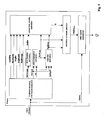
Fig. 1. Fig. 1 depicts the block diagram of the preferred method and apparatus for the objective video quality assessment based on the estimation of the visibility of packet loss events. In particular, it is shown that it is a no-reference bit-stream based method which extracts or computes eight features from the received bit-stream to evaluate the perceptual impact of every packet loss. Subsequently, the extracted features and the predicted value for the visibility of the packet loss are used to assess the overall quality of the video bit stream. - At the receiver, a probe device captures the bit stream and extracts or computes a number of features that are utilized for the video quality assessment. The features are either extracted directly by partly decoding the bit stream or combining information from the reconstructed pixels (full decoding of the bit stream). Then, the extracted features are fed to the module which is responsible for determining the visibility of each packet loss event. This module assigns a continuous estimate of visibility for each packet loss event (isolated packet losses or combination of events) that occurs within a specific time duration. Subsequently, the probability estimate of the packet loss visibility module is combined with the previously extracted features to assess the overall quality of the sequence. Specifically, based on the probability estimates of the visibility of each packet loss, the extracted features are weighted in the final algorithm to reflect that every packet loss produces unequally perceived degradations to the video sequence. Finally, the probe device outputs the predicted value of video quality, Q.
- The following describes the features preferably extracted from the bit stream to determine the visibility of packet losses and the objective quality of the video sequences. It must be noted that in this example the analysis is based on streams encoded according to the H.264/AVC video coding standard (T. Wiegand, G. J. Sullivan, G. Bjontegaard, and A. Luthra, "Overview of the H.264/AVC video coding standard," IEEE Trans. on Circuits and Systems for Video Technology, vol. 13, no. 7, Jul. 2003), but the method could be applied to any video coding standard with minor modifications for the computation of the corresponding features.
- One of the properties that need to be computed for the estimation of the perceptual degradation caused by a packet loss is the "frame type" of all frames and in particular the frame affected by the loss. The possible values for the "frame type" property include "Intra-frame" or "Key-Frame" (below called I-frame), "Predicted-Frame" (below called P-frame) and "Bidirectional-Frame" (below called B-frame). Only I-frames can be decoded without referencing information of any prior frames. In contrary, P-frames depend on one or more predecessors called "reference frames", because the information transmitted for a P-frame mainly consists of the difference between the video-frame it describes and its references. Therefore, packet losses within an I-frame or its consecutive P-frames propagate into following frames, even if these following frames do not contain any lost packets themselves. Due to this mechanism, a single packet loss error may linger through long parts of a video sequence, until the next error free I-frame occurs. Errors in P-frames and particularly in I-frames may therefore have a high visibility. The same reference frame mechanism is true for B-frames, but, since B-frames in general do not serve as references themselves, an error in a B-frame will only cause degradation in this single frame.
- The chain of video frames between two successive I-frames is called "Group of Pictures" (GoP). In most of the cases P and B-frames in a GoP follow a more or less strict pattern like the typical GoP-pattern: "I, B, B, P, B, B, P ....". Let N denote the GOP-length, that is the distance between two successive I-frames. Then, if the first packet loss occurs t frames after the first I-frame of a specific GOP, the first feature that is extracted is the number of frames that are degraded due to the packet loss, called ErrDur. This property is computed as (see
Fig. 2 ):
- Thus, if the packet loss occurs in the first frame (which is an I-frame) then t = 1, and the number of frames that are impaired by the packet loss is N, that is equal to the number of frames in the GOP.
- Subsequently, the average magnitude of motion vectors, AvgMv, is preferably computed which reflects the mean motion vector in the horizontal and vertical directions of all macroblocks (mb) affected by the loss. Let v n = [vn,x, vn,y] denote the motion vector of the n-th macroblock in the frame in which the packet loss occurred. Then, the term AvgMv is computed as:

where L is the cardinality of the set of the macroblocks that are lost in frame n due to the packet loss. Apparently, since the motion vector information for the lost macroblocks cannot be recovered, this information is estimated from their temporal neighbours. That is, for every missing macroblock, the motion vector information is recovered from the co-located macroblock in the previous correctly received frame. - Additionally, the average motion vector difference, AvgMvDiff , may be computed from the bit stream. In H.264/AVC, to exploit the redundancy among motion vectors, only the difference between the motion vector of a block and its predicted motion vector from neighbouring macroblocks is included in the bit stream. This feature is extremely meaningful in sequences with predictable movement (e.g., panning), where the average motion may be large, but the motion vector differences encoded in the bit stream are small. Let vd n = [vdn,x, vdn,y] denote the motion vector difference of the n-th macroblock in the frame in which the packet loss occurred. Then, the term AvgMvDiff is computed as:

where L is the cardinality of the set of the macroblocks that are lost in frame n due to the packet loss. Similarly to the case above, since the motion vector information for the lost macroblocks cannot be recovered, this information is estimated from their temporal neighbours. That is, for every missing macroblock, the motion vector information is recovered from the co-located macroblock in the previous correctly received frame. - Another feature that is preferably extracted from the received video bit stream is the energy of the residual, ResEnergy , which is contained in the missing macroblocks and is computed from the transform coefficients of the prediction error. Let cb,i,j , b=0,...,3, i=0,...,3, and j=0, ..., 3 denote the transform coefficient at the i-th row and j-column of the b-th 4x4 block of a macroblock (see
Figure 3 ). Then, the residual energy is computed as:
where l and L are defined as above. - Another feature that may be extracted is the maximum number of partitions, called MaxPartNr, in the frame where the loss occurs. In H.264/AVC, each 16x16 macroblock can be further split in smaller blocks for the motion estimation process, i.e. blocks of size 16x8, 8x16, or 8x8. If the 8x8 partition size is chosen, each 8x8 partition may be further divided in sub-partitions of size 8x8, 8x4, 4x8, or 4x4 luma samples. Thus, the parameter MaxPartNr is equal to the maximum number of partitions of the correctly received macroblocks in the frame where the loss occurs. If all the macroblocks are erased (that is, if the whole frame is lost) then the parameter is derived from the previous received frame.
- The sixth feature that is extracted from the received bit stream is the number of macroblocks that are non-decodable due to the packet loss and need to be concealed, called LostMbs below.
- Additionally, based on the motion vector information and the type of macroblocks, a binary error propagation map may be generated for each picture, which denotes the pixels in each picture that are impacted by the packet loss(es) either due to the innovation error or due to the propagation of the error to the subsequent frames of the same GOP due to the predictive coding. Let I(x,y,k) denote the value of the binary error map at location (x,y) of the k-th frame, x = 1, 2, ..., H, and y = 1, 2,..., W where H, W are the height and width of each frame of the video sequence, respectively. Also, k=1,...,K, where K is the number of frames that contain impaired pixels due to the packet loss. The value for those pixels that are either impaired due to the packet loss or reference those areas and are likely to be erroneous is set to one, otherwise the value is set to zero. Thus:

- In other words, the value in the propagation map array is set to one for all pixels that are not identical between the original video sequence and the reconstructed image of the decoder within the probe due to the error caused by the packet loss and its propagation. An example of the derivation of the error propagation maps is depicted in
Fig. 4 . -
Fig. 4 depicts the error propagation maps for four consecutive frames in the video sequence to demonstrate how the initial error caused by a packet loss spreads into the following frames that reference the initial frame for their prediction. In particular, inFig. 4a , the dark region corresponds to the area that cannot be decoded because the information for these pixels was contained in a packet which was erased. As a result, the decoder needs to conceal (usually using temporal or spatial neighbours) this area to replace the missing pixels. Since the concealment can not recover the original information exactly, some degradation is introduced to that frames.Figs. 4b, 4c, and 4d show how this error propagates into the following frames. Dark areas correspond to pixels that reference information from the initially lost (and concealed) region and are thus prone to be erroneous as well. - The packet loss occurs in the first frame (the dark area in the figure denotes the macroblocks that have been erased due to the packet loss) and propagates to the subsequent frames that reference the affected area of the first frame for the prediction process. It is noted that in alternative embodiments the error propagation map may be estimated at the macroblock level, meaning that propagation is tracked for every macroblock instead for every pixel.
- Based on the error propagation maps, the total number of impaired pixels due to a packet loss, called ErrProp, is computed as:

- Finally, another feature may be extracted based on the motion vectors, the macroblock types and the residuals, termed EstErr, to quantify the magnitude of the distortion induced due to the packet loss and due to error propagation which enables the estimation of the induced mean squared error (MSE) in a no-reference manner. The method for estimating the induced distortion is out of scope of this invention, thus any method known to the skilled person could be used, for example the method proposed in M. Naccari, M. Tagliasacchi, and S. Tubaro, "No-reference video quality monitoring for H.264/AVC coded video," IEEE Trans. on Multimedia, vol. 11, no. 5, pp. 932-946, Aug. 2009.
- In the shown example, the aforementioned eight features are extracted for every packet loss that occurs in a GOP. When more than one packet loss appear in the same GOP, then in the preferred embodiment the maximum value is selected for the ErrorDur, and MaxPartNr , while for the other features their sum is considered as the final features. However, in other embodiments, the features extracted from every packet loss within a GOP can be combined differently, for example by computing the mean, the median, or any other function. Thus, within every GOP, the following feature vector is extracted which is used for the estimation of the visibility of packet loss events:

- It must be noted, that in other embodiments of the present invention, any number and combination of the aforementioned features could be used. This is mainly meaningful when it is desired not to compute some features (e.g., due to complexity reasons or cost implementation).
- For the classification of packet loss visibility based on the extracted features of each packet loss event, a technique based on Support Vector Regression (SVR) is employed. With this method, the input feature vector is mapped to a high-dimensional feature space using a nonlinear mapping function and then a linear model is constructed in this feature space. The algorithm operates in two stages: the training stage in which the training data are used to tune the parameters of the model, and the evaluation stage in which the model outputs the predicted value for the input feature vector. These two stages are described in detail in the following.
- In the training stage, a set of n training data, denoted by {(f 1, y1), (f 2, y2), ..., (f n, yn),},


- At the evaluation stage, the algorithm receives an input feature vector f (as described in Eq. (7)) and the predicted value of the visibility of each loss, V, is given by:

where K(.,.) is the kernel function, and f i, i=1,..., n, are the feature vectors used as training data. In the present invention, the following function has been selected as the kernel function, which is also known as the Radial Basis Function (RBF):
- In the present invention, the value of γ is selected to be equal to 2. Also, any other kernel function could be used in other embodiments. Furthermore, the predicted value V for the visibility of a packet loss can be converted into a binary value, if it is desirable to classify a packet loss into one of the following two cases: visible or invisible. In that case, the binary predicted value of a packet loss, denoted as VB, can be computed as:

- When the algorithm operates at the evaluation stage only and does not need to train on new data, the stored parameters are used and the visibility V of each packet loss event is predicted as defined in Eq. (8). The extracted features that were mentioned above are refined so that they reflect the predicted value of the visibility of each packet loss and are weighted accordingly, as analyzed in the following section.
- The proposed bit stream based video quality assessment model is a combination of the degradation caused by the compression of the video sequences, Qcod, and the quality degradation due to packet loss during transmission (Qtrans ). Thus, the overall quality is given by:

where Q denotes the overall quality of the sequence and Q0 denotes the source quality of the video inserted in the transmission chain. The Qcod term is computed by:
where B is the bit rate of the video sequence, and a1, a2, and a3 are constants. In the present example, the values of a1 , a2, and a3 are selected equal to 89.33, -1.21, and 11.47. - The channel-induced visual degradation term reflects the distortion that is caused by the packet loss, the extent of its propagation and the intensity in human visual perception. For this reason, the following formula is used for Qtrans :

- Here, the index i is used to denote a particular single packet loss event that occurs during the sequence and f(.,.) represents any suitable function. In other words, the overall degradation due to transmission errors is a function of the visibility of every packet loss, the error that is induced to the frame where the packet loss occurs and the propagation of the error into the subsequent frames.
- In the following, two embodiments of the present invention are presented to represent the function f(.,.) mentioned above with specific formulas.
- In the first embodiment, Eq. (13) is rewritten as:

where a4, a5, and a6 are constants determined by regression, i is an index referring to every individual packet loss, EstErri and ErrPropi are the extracted features as mentioned above associated with each packet loss. Thus, the model takes into account the importance of each packet loss for the determination of the visual degradation and utilizes the output of the visibility estimation to weight the induced distortion of every packet loss. In the present embodiment, the values of a4, a5 , and a6 are selected equal to 0.023, 0.000176, and 0.0000465. - In the second embodiment, which is depicted in
Fig. 5 , another implementation is employed for the function f(.,.) of Eq. (14). Let i denote the index of an individual packet loss occurring within a GOP. Also, let EstErri be the induced distortion in the frame where the i-th packet loss occurred, estimated as explained above in the feature extraction section. Then, the visible degradation associated with this packet loss is given by:
- Also, let


where I(x,y,k) denotes the value of the binary error map at location (x,y) of the k-th frame, x = 1, 2, ..., H, and y = 1, 2,..., W where H, W are the height and width of each frame of the video sequence, respectively. Then, the perceived degradation in the subsequent frame k, k>0, due to error propagation of the i-th packet loss is given by:
- Here,


Fig. 6 . In this figure, the dark area in frame with index t corresponds to the term

- Then, the overall visual degradation caused by the i-th packet loss, termed VisEstErri , can be considered as the summation of the degradations caused to all the frames Ki that were impaired due to this packet loss, thus:

- Note that the summation starts from the index zero to factor in the initial distortion as described in Eq. (15). The total distortion within a specific GOP is computed as the summation of the distortions generated by all packet losses occurring within this GOP, thus:

- Finally, let G denote the total number of GOPs within a sequence, and T denote the total duration of the sequence. Then, the overall distortion due to transmission errors is given by:


- In the preferred embodiment of this second type, we set

- Where ϑ and ξ are constants that are, for example, determined in a regression procedure using quality ratings as target values.
- While the invention has been illustrated and described in detail in the drawings and foregoing description, such illustration and description are to be considered illustrative or exemplary and not restrictive. It will be understood that changes and modifications may be made by those of ordinary skill within the scope of the following claims. In particular, the present invention covers further embodiments with any combination of features from different embodiments described above and below.
- Furthermore, in the claims the word "comprising" does not exclude other elements or steps, and the indefinite article "a" or "an" does not exclude a plurality. A single unit may fulfil the functions of several features recited in the claims. The terms "essentially", "about", "approximately" and the like in connection with an attribute or a value particularly also define exactly the attribute or exactly the value, respectively. Any reference signs in the claims should not be construed as limiting the scope.
Claims (11)
- Method for assessing the quality of a transmitted video signal sequence at the receiver side, the method comprising the steps of:a) capturing the input video bit stream and supplying it to a video bit stream analyzer;b) extracting at least one feature or a set of features from the captured input video bit stream by the bit stream analyzer;c) supplying the extracted feature or set of features to a packet loss visibility estimation module;d) determining, by the packet loss visibility estimation module employing the supplied extracted features of the video bit stream, the continuous probability of visibility for each packet loss event which occurred within a specific time interval;e) employing the continuous probability of packet loss visibility, determined by the packet loss visibility estimation module, as a weighting factor of at least one feature or set of features extracted from the video bit stream to calculate an estimate of the overall quality, Q, of the transmitted video sequence;wherein step (d) employs at least one bit stream feature from the group comprising: frame type, average magnitude of motion vectors (AvgMv), average motion vector difference (AvgMvDiff), energy of residuals (ResEnergy), maximum number of partitions (MaxPartNr), number of non-decodable macroblocks (LostMbs), motion vector information (mv), type of macroblocks (mb type); and
wherein step (e) combines the packet loss visibility estimate (V) with the determined magnitude of distortion (EstErr) and the computed total number of impaired pixels due to packet loss (ErrProp). - The method of claim 1, wherein feature extraction according to step (b) is performed directly by partly decoding the video bit stream, where "partly" means without decoding the bit stream to the pixel level.
- The method of claim 1, wherein feature extraction according to step (b) is performed by full decoding of the video bit stream and by combining information from the reconstructed pixels of the video signal.
- The method of any one of claims 1 to 3, wherein, based on the extracted feature "frame type" the number of frames (ErrDur) degraded by a packet loss is determined and used for the prediction of the probability of packet loss visibility as well as for combining it with the visibility probability to estimate the impact of packet loss on visual quality.
- The method of any one of claims 1 to 4, wherein a binary error propagation map is generated for each picture of the video signal sequence based on the motion vector information and the type of macroblocks.
- The method of claim 5, wherein based on the error propagation map and frame type information the number of frames (ErrDur) degraded by a packet loss is determined.
- The method of claim 5 or 6, wherein based on the binary error propagation map the total number of impaired pixels due to packet loss (ErrProp) is computed.
- The method of any one of claims 1 to 7, wherein the magnitude of distortion (EstErr) induced due to packet loss and error propagation is determined based on the motion vectors, the macroblock types, and the residuals.
- The method of any one of the preceding claims, wherein step (d) is performed using a support vector regression technique by mapping the input feature vector, comprised from the aforementioned features, to a high-dimensional feature space using a nonlinear mapping function, and constructing a linear model in the feature space.
- The method of any one of the preceding claims, further comprising between steps d) and e) the step of estimating the overall visible distortion generated by temporal pooling of all packet losses occurring within the video signal sequence.
- Apparatus for assessing the quality of a transmitted video signal sequence at the receiver side, the apparatus comprising:a video bit stream analyzer receiving the captured input video bit stream, and configured for extracting at least one feature or a set of features from the captured input video bit stream;a packet loss visibility estimation module receiving the extracted feature or set of features, the packet loss visibility estimation module configured for determining the visibility of a packet loss occurred during transmission of the video signal by predicting the continuous probability of visibility for each packet loss event occurred within a specific time interval;a combiner for combining the continuous probability of packet loss visibility, determined by the packet loss visibility module, as a weighting factor of at least one feature or set of features extracted from the video bit stream to calculate an estimate of the overall quality, Q, of the transmitted video signal sequence;wherein the packet loss visibility estimation module employs at least one bit stream feature from the group comprising: frame type, average magnitude of motion vectors (AvgMv), average motion vector difference (AvgMvDiff), energy of residuals (ResEnergy), maximum number of partitions (MaxPartNr), number of non-decodable macroblocks (LostMbs), motion vector information (mv), type of macroblocks (mb type); andwherein the combiner combines the packet loss visibility estimate (V) with the determined magnitude of distortion (EstErr) and the computed total number of impaired pixels due to packet loss (ErrProp).
Priority Applications (3)
| Application Number | Priority Date | Filing Date | Title |
|---|---|---|---|
| EP11763619.1A EP2649801B1 (en) | 2010-12-10 | 2011-09-02 | Method and apparatus for objective video quality assessment based on continuous estimates of packet loss visibility |
| PL11763619T PL2649801T3 (en) | 2010-12-10 | 2011-09-02 | Method and apparatus for objective video quality assessment based on continuous estimates of packet loss visibility |
| HRP20150481TT HRP20150481T1 (en) | 2010-12-10 | 2015-05-04 | Method and apparatus for objective video quality assessment based on continuous estimates of packet loss visibility |
Applications Claiming Priority (3)
| Application Number | Priority Date | Filing Date | Title |
|---|---|---|---|
| EP10194580 | 2010-12-10 | ||
| EP11763619.1A EP2649801B1 (en) | 2010-12-10 | 2011-09-02 | Method and apparatus for objective video quality assessment based on continuous estimates of packet loss visibility |
| PCT/EP2011/065192 WO2012076203A1 (en) | 2010-12-10 | 2011-09-02 | Method and apparatus for objective video quality assessment based on continuous estimates of packet loss visibility |
Publications (2)
| Publication Number | Publication Date |
|---|---|
| EP2649801A1 EP2649801A1 (en) | 2013-10-16 |
| EP2649801B1 true EP2649801B1 (en) | 2015-04-15 |
Family
ID=44719874
Family Applications (1)
| Application Number | Title | Priority Date | Filing Date |
|---|---|---|---|
| EP11763619.1A Active EP2649801B1 (en) | 2010-12-10 | 2011-09-02 | Method and apparatus for objective video quality assessment based on continuous estimates of packet loss visibility |
Country Status (11)
| Country | Link |
|---|---|
| US (1) | US9232217B2 (en) |
| EP (1) | EP2649801B1 (en) |
| JP (1) | JP6022473B2 (en) |
| KR (1) | KR101857842B1 (en) |
| CN (1) | CN103283239B (en) |
| BR (1) | BR112013014367B1 (en) |
| ES (1) | ES2541282T3 (en) |
| HR (1) | HRP20150481T1 (en) |
| HU (1) | HUE026522T2 (en) |
| PL (1) | PL2649801T3 (en) |
| WO (1) | WO2012076203A1 (en) |
Families Citing this family (16)
| Publication number | Priority date | Publication date | Assignee | Title |
|---|---|---|---|---|
| GB2468878B (en) * | 2009-03-24 | 2014-11-19 | Strategy & Technology Ltd | A device comprising at least one receiver for a testing device |
| US8804815B2 (en) * | 2011-07-29 | 2014-08-12 | Dialogic (Us) Inc. | Support vector regression based video quality prediction |
| GB2497915B (en) * | 2011-10-25 | 2015-09-09 | Skype | Estimating quality of a video signal |
| US9661348B2 (en) * | 2012-03-29 | 2017-05-23 | Intel Corporation | Method and system for generating side information at a video encoder to differentiate packet data |
| CN104396238B (en) * | 2012-07-17 | 2016-12-28 | 汤姆逊许可公司 | The other video quality assessment of bitstream stage |
| CA2881860A1 (en) * | 2012-08-27 | 2014-03-06 | Thomson Licensing | Method and apparatus for estimating motion homogeneity for video quality assessment |
| US20150341667A1 (en) * | 2012-12-21 | 2015-11-26 | Thomson Licensing | Video quality model, method for training a video quality model, and method for determining video quality using a video quality model |
| GB2513090B (en) | 2013-01-28 | 2019-12-11 | Microsoft Technology Licensing Llc | Conditional concealment of lost video data |
| EP2954677B1 (en) * | 2013-02-07 | 2019-07-31 | InterDigital CE Patent Holdings | Method and apparatus for context-based video quality assessment |
| EP2954676A4 (en) * | 2013-02-07 | 2016-07-13 | Thomson Licensing | Method and apparatus for context-based video quality assessment |
| CN103108210B (en) * | 2013-03-07 | 2015-04-15 | 福州大学 | No-reference video quality evaluation method based on airspace complexity |
| US9674515B2 (en) * | 2013-07-11 | 2017-06-06 | Cisco Technology, Inc. | Endpoint information for network VQM |
| CN104092960B (en) * | 2014-07-26 | 2017-06-06 | 福州大学 | A kind of video source switch method of view-based access control model subjective feeling |
| JP6499993B2 (en) * | 2016-05-18 | 2019-04-10 | 株式会社ソニー・インタラクティブエンタテインメント | Information processing apparatus, information processing system, and information processing method |
| CN111372071B (en) * | 2018-12-25 | 2022-07-19 | 浙江宇视科技有限公司 | Method and device for collecting video image abnormal information |
| WO2020180424A1 (en) | 2019-03-04 | 2020-09-10 | Iocurrents, Inc. | Data compression and communication using machine learning |
Family Cites Families (6)
| Publication number | Priority date | Publication date | Assignee | Title |
|---|---|---|---|---|
| JP4327674B2 (en) | 2004-07-21 | 2009-09-09 | 日本電信電話株式会社 | Video quality control method and video quality control system |
| US8130274B2 (en) * | 2004-10-18 | 2012-03-06 | Nippon Telegraph And Telephone Corporation | Video quality objective assessment device, assessment method, and program |
| JP4787210B2 (en) | 2007-05-30 | 2011-10-05 | 日本電信電話株式会社 | Video quality estimation method, apparatus, and program |
| EP2106154A1 (en) | 2008-03-28 | 2009-09-30 | Deutsche Telekom AG | Audio-visual quality estimation |
| US20100110199A1 (en) * | 2008-11-03 | 2010-05-06 | Stefan Winkler | Measuring Video Quality Using Partial Decoding |
| JP5670551B2 (en) * | 2010-04-30 | 2015-02-18 | トムソン ライセンシングThomson Licensing | Method and apparatus for evaluating the quality of a video stream |
-
2011
- 2011-09-02 EP EP11763619.1A patent/EP2649801B1/en active Active
- 2011-09-02 CN CN201180060011.3A patent/CN103283239B/en active Active
- 2011-09-02 HU HUE11763619A patent/HUE026522T2/en unknown
- 2011-09-02 WO PCT/EP2011/065192 patent/WO2012076203A1/en active Application Filing
- 2011-09-02 BR BR112013014367-3A patent/BR112013014367B1/en active IP Right Grant
- 2011-09-02 US US13/991,907 patent/US9232217B2/en active Active
- 2011-09-02 ES ES11763619.1T patent/ES2541282T3/en active Active
- 2011-09-02 PL PL11763619T patent/PL2649801T3/en unknown
- 2011-09-02 JP JP2013542419A patent/JP6022473B2/en active Active
- 2011-09-02 KR KR1020137017415A patent/KR101857842B1/en active IP Right Grant
-
2015
- 2015-05-04 HR HRP20150481TT patent/HRP20150481T1/en unknown
Also Published As
| Publication number | Publication date |
|---|---|
| HRP20150481T1 (en) | 2015-06-05 |
| US9232217B2 (en) | 2016-01-05 |
| PL2649801T3 (en) | 2015-08-31 |
| CN103283239A (en) | 2013-09-04 |
| KR101857842B1 (en) | 2018-05-14 |
| JP6022473B2 (en) | 2016-11-09 |
| BR112013014367B1 (en) | 2022-07-12 |
| ES2541282T3 (en) | 2015-07-17 |
| US20130271668A1 (en) | 2013-10-17 |
| HUE026522T2 (en) | 2016-06-28 |
| CN103283239B (en) | 2016-10-05 |
| EP2649801A1 (en) | 2013-10-16 |
| KR20140008508A (en) | 2014-01-21 |
| WO2012076203A1 (en) | 2012-06-14 |
| BR112013014367A2 (en) | 2021-07-27 |
| JP2014502113A (en) | 2014-01-23 |
Similar Documents
| Publication | Publication Date | Title |
|---|---|---|
| EP2649801B1 (en) | Method and apparatus for objective video quality assessment based on continuous estimates of packet loss visibility | |
| JP5964852B2 (en) | Method and apparatus for evaluating video signal quality during video signal encoding and transmission | |
| CN109510919B (en) | Method, apparatus, and medium for scene change detection for perceptual quality assessment | |
| US20130208814A1 (en) | Methods and apparatuses for temporal synchronisation between the video bit stream and the output video sequence | |
| US9077972B2 (en) | Method and apparatus for assessing the quality of a video signal during encoding or compressing of the video signal | |
| US20150296224A1 (en) | Perceptually driven error correction for video transmission | |
| WO2013075318A1 (en) | Video quality measurement | |
| Yamada et al. | No-reference video quality estimation based on error-concealment effectiveness | |
| Argyropoulos et al. | No-reference bit stream model for video quality assessment of H. 264/AVC video based on packet loss visibility | |
| EP2708028B1 (en) | Method and device for estimating video quality on bitstream level | |
| Reibman et al. | Predicting packet-loss visibility using scene characteristics | |
| Chen et al. | Hybrid distortion ranking tuned bitstream-layer video quality assessment | |
| US9723266B1 (en) | Lightweight content aware bit stream video quality monitoring service | |
| Huang | No-reference video quality assessment by HEVC codec analysis | |
| Liu et al. | Review of ITU-T parametric models for compressed video quality estimation | |
| Uzair et al. | No-reference transmission distortion modelling for H. 264/AVC-coded video | |
| Hassan et al. | Skip length and inter-starvation distance as a combined metric to assess the quality of transmitted video | |
| Naccari et al. | Subjective evaluation of a no-reference video quality monitoring algorithm for H. 264/AVC video over a noisy channel | |
| Song et al. | Objective quality assessment of HD video based on compressed domain | |
| Chin | Video Quality Evaluation in IP Networks | |
| CN104488265A (en) | Content-dependent video quality model for video streaming services |
Legal Events
| Date | Code | Title | Description |
|---|---|---|---|
| PUAI | Public reference made under article 153(3) epc to a published international application that has entered the european phase |
Free format text: ORIGINAL CODE: 0009012 |
|
| 17P | Request for examination filed |
Effective date: 20130605 |
|
| AK | Designated contracting states |
Kind code of ref document: A1 Designated state(s): AL AT BE BG CH CY CZ DE DK EE ES FI FR GB GR HR HU IE IS IT LI LT LU LV MC MK MT NL NO PL PT RO RS SE SI SK SM TR |
|
| DAX | Request for extension of the european patent (deleted) | ||
| REG | Reference to a national code |
Ref country code: DE Ref legal event code: R079 Ref document number: 602011015714 Country of ref document: DE Free format text: PREVIOUS MAIN CLASS: H04N0007640000 Ipc: H04N0019000000 |
|
| RIC1 | Information provided on ipc code assigned before grant |
Ipc: H04N 19/00 20140101AFI20141015BHEP |
|
| GRAP | Despatch of communication of intention to grant a patent |
Free format text: ORIGINAL CODE: EPIDOSNIGR1 |
|
| INTG | Intention to grant announced |
Effective date: 20141121 |
|
| GRAS | Grant fee paid |
Free format text: ORIGINAL CODE: EPIDOSNIGR3 |
|
| GRAA | (expected) grant |
Free format text: ORIGINAL CODE: 0009210 |
|
| AK | Designated contracting states |
Kind code of ref document: B1 Designated state(s): AL AT BE BG CH CY CZ DE DK EE ES FI FR GB GR HR HU IE IS IT LI LT LU LV MC MK MT NL NO PL PT RO RS SE SI SK SM TR |
|
| REG | Reference to a national code |
Ref country code: GB Ref legal event code: FG4D Ref country code: CH Ref legal event code: EP |
|
| RIN1 | Information on inventor provided before grant (corrected) |
Inventor name: ARGYROPOULOS, SAVVAS Inventor name: RAAKE, ALEXANDER Inventor name: GARCIA, MARIE-NEIGE Inventor name: FEITEN, BERNHARD Inventor name: LIST, PETER |
|
| REG | Reference to a national code |
Ref country code: HR Ref legal event code: TUEP Ref document number: P20150481 Country of ref document: HR |
|
| REG | Reference to a national code |
Ref country code: IE Ref legal event code: FG4D |
|
| REG | Reference to a national code |
Ref country code: AT Ref legal event code: REF Ref document number: 722550 Country of ref document: AT Kind code of ref document: T Effective date: 20150515 |
|
| REG | Reference to a national code |
Ref country code: DE Ref legal event code: R096 Ref document number: 602011015714 Country of ref document: DE Effective date: 20150528 |
|
| REG | Reference to a national code |
Ref country code: HR Ref legal event code: T1PR Ref document number: P20150481 Country of ref document: HR |
|
| REG | Reference to a national code |
Ref country code: CH Ref legal event code: NV Representative=s name: VOSSIUS AND PARTNER, CH |
|
| REG | Reference to a national code |
Ref country code: NL Ref legal event code: T3 |
|
| REG | Reference to a national code |
Ref country code: RO Ref legal event code: EPE |
|
| REG | Reference to a national code |
Ref country code: ES Ref legal event code: FG2A Ref document number: 2541282 Country of ref document: ES Kind code of ref document: T3 Effective date: 20150717 |
|
| REG | Reference to a national code |
Ref country code: PL Ref legal event code: T3 |
|
| REG | Reference to a national code |
Ref country code: SK Ref legal event code: T3 Ref document number: E 18749 Country of ref document: SK Ref country code: GR Ref legal event code: EP Ref document number: 20150401145 Country of ref document: GR Effective date: 20150720 |
|
| REG | Reference to a national code |
Ref country code: FR Ref legal event code: PLFP Year of fee payment: 5 |
|
| REG | Reference to a national code |
Ref country code: LT Ref legal event code: MG4D |
|
| PG25 | Lapsed in a contracting state [announced via postgrant information from national office to epo] |
Ref country code: NO Free format text: LAPSE BECAUSE OF FAILURE TO SUBMIT A TRANSLATION OF THE DESCRIPTION OR TO PAY THE FEE WITHIN THE PRESCRIBED TIME-LIMIT Effective date: 20150715 Ref country code: FI Free format text: LAPSE BECAUSE OF FAILURE TO SUBMIT A TRANSLATION OF THE DESCRIPTION OR TO PAY THE FEE WITHIN THE PRESCRIBED TIME-LIMIT Effective date: 20150415 Ref country code: PT Free format text: LAPSE BECAUSE OF FAILURE TO SUBMIT A TRANSLATION OF THE DESCRIPTION OR TO PAY THE FEE WITHIN THE PRESCRIBED TIME-LIMIT Effective date: 20150817 Ref country code: LT Free format text: LAPSE BECAUSE OF FAILURE TO SUBMIT A TRANSLATION OF THE DESCRIPTION OR TO PAY THE FEE WITHIN THE PRESCRIBED TIME-LIMIT Effective date: 20150415 |
|
| PG25 | Lapsed in a contracting state [announced via postgrant information from national office to epo] |
Ref country code: IS Free format text: LAPSE BECAUSE OF FAILURE TO SUBMIT A TRANSLATION OF THE DESCRIPTION OR TO PAY THE FEE WITHIN THE PRESCRIBED TIME-LIMIT Effective date: 20150815 Ref country code: RS Free format text: LAPSE BECAUSE OF FAILURE TO SUBMIT A TRANSLATION OF THE DESCRIPTION OR TO PAY THE FEE WITHIN THE PRESCRIBED TIME-LIMIT Effective date: 20150415 Ref country code: LV Free format text: LAPSE BECAUSE OF FAILURE TO SUBMIT A TRANSLATION OF THE DESCRIPTION OR TO PAY THE FEE WITHIN THE PRESCRIBED TIME-LIMIT Effective date: 20150415 |
|
| REG | Reference to a national code |
Ref country code: DE Ref legal event code: R097 Ref document number: 602011015714 Country of ref document: DE |
|
| PG25 | Lapsed in a contracting state [announced via postgrant information from national office to epo] |
Ref country code: DK Free format text: LAPSE BECAUSE OF FAILURE TO SUBMIT A TRANSLATION OF THE DESCRIPTION OR TO PAY THE FEE WITHIN THE PRESCRIBED TIME-LIMIT Effective date: 20150415 Ref country code: EE Free format text: LAPSE BECAUSE OF FAILURE TO SUBMIT A TRANSLATION OF THE DESCRIPTION OR TO PAY THE FEE WITHIN THE PRESCRIBED TIME-LIMIT Effective date: 20150415 |
|
| PLBE | No opposition filed within time limit |
Free format text: ORIGINAL CODE: 0009261 |
|
| STAA | Information on the status of an ep patent application or granted ep patent |
Free format text: STATUS: NO OPPOSITION FILED WITHIN TIME LIMIT |
|
| 26N | No opposition filed |
Effective date: 20160118 |
|
| PG25 | Lapsed in a contracting state [announced via postgrant information from national office to epo] |
Ref country code: LU Free format text: LAPSE BECAUSE OF FAILURE TO SUBMIT A TRANSLATION OF THE DESCRIPTION OR TO PAY THE FEE WITHIN THE PRESCRIBED TIME-LIMIT Effective date: 20150902 Ref country code: MC Free format text: LAPSE BECAUSE OF FAILURE TO SUBMIT A TRANSLATION OF THE DESCRIPTION OR TO PAY THE FEE WITHIN THE PRESCRIBED TIME-LIMIT Effective date: 20150415 |
|
| PG25 | Lapsed in a contracting state [announced via postgrant information from national office to epo] |
Ref country code: SI Free format text: LAPSE BECAUSE OF FAILURE TO SUBMIT A TRANSLATION OF THE DESCRIPTION OR TO PAY THE FEE WITHIN THE PRESCRIBED TIME-LIMIT Effective date: 20150415 |
|
| REG | Reference to a national code |
Ref country code: HU Ref legal event code: AG4A Ref document number: E026522 Country of ref document: HU |
|
| REG | Reference to a national code |
Ref country code: IE Ref legal event code: MM4A |
|
| REG | Reference to a national code |
Ref country code: CH Ref legal event code: PFA Owner name: DEUTSCHE TELEKOM AG, DE Free format text: FORMER OWNER: DEUTSCHE TELEKOM AG, DE |
|
| PG25 | Lapsed in a contracting state [announced via postgrant information from national office to epo] |
Ref country code: IE Free format text: LAPSE BECAUSE OF NON-PAYMENT OF DUE FEES Effective date: 20150902 |
|
| REG | Reference to a national code |
Ref country code: FR Ref legal event code: PLFP Year of fee payment: 6 |
|
| REG | Reference to a national code |
Ref country code: AT Ref legal event code: UEP Ref document number: 722550 Country of ref document: AT Kind code of ref document: T Effective date: 20150415 |
|
| PG25 | Lapsed in a contracting state [announced via postgrant information from national office to epo] |
Ref country code: MT Free format text: LAPSE BECAUSE OF FAILURE TO SUBMIT A TRANSLATION OF THE DESCRIPTION OR TO PAY THE FEE WITHIN THE PRESCRIBED TIME-LIMIT Effective date: 20150415 |
|
| PG25 | Lapsed in a contracting state [announced via postgrant information from national office to epo] |
Ref country code: SM Free format text: LAPSE BECAUSE OF FAILURE TO SUBMIT A TRANSLATION OF THE DESCRIPTION OR TO PAY THE FEE WITHIN THE PRESCRIBED TIME-LIMIT Effective date: 20150415 Ref country code: BG Free format text: LAPSE BECAUSE OF FAILURE TO SUBMIT A TRANSLATION OF THE DESCRIPTION OR TO PAY THE FEE WITHIN THE PRESCRIBED TIME-LIMIT Effective date: 20150415 |
|
| PG25 | Lapsed in a contracting state [announced via postgrant information from national office to epo] |
Ref country code: SE Free format text: LAPSE BECAUSE OF FAILURE TO SUBMIT A TRANSLATION OF THE DESCRIPTION OR TO PAY THE FEE WITHIN THE PRESCRIBED TIME-LIMIT Effective date: 20150415 Ref country code: CY Free format text: LAPSE BECAUSE OF FAILURE TO SUBMIT A TRANSLATION OF THE DESCRIPTION OR TO PAY THE FEE WITHIN THE PRESCRIBED TIME-LIMIT Effective date: 20150415 |
|
| REG | Reference to a national code |
Ref country code: FR Ref legal event code: PLFP Year of fee payment: 7 |
|
| PG25 | Lapsed in a contracting state [announced via postgrant information from national office to epo] |
Ref country code: MK Free format text: LAPSE BECAUSE OF FAILURE TO SUBMIT A TRANSLATION OF THE DESCRIPTION OR TO PAY THE FEE WITHIN THE PRESCRIBED TIME-LIMIT Effective date: 20150415 |
|
| REG | Reference to a national code |
Ref country code: FR Ref legal event code: PLFP Year of fee payment: 8 |
|
| PG25 | Lapsed in a contracting state [announced via postgrant information from national office to epo] |
Ref country code: AL Free format text: LAPSE BECAUSE OF FAILURE TO SUBMIT A TRANSLATION OF THE DESCRIPTION OR TO PAY THE FEE WITHIN THE PRESCRIBED TIME-LIMIT Effective date: 20150415 |
|
| REG | Reference to a national code |
Ref country code: HR Ref legal event code: ODRP Ref document number: P20150481 Country of ref document: HR Payment date: 20190826 Year of fee payment: 9 |
|
| REG | Reference to a national code |
Ref country code: HR Ref legal event code: ODRP Ref document number: P20150481 Country of ref document: HR Payment date: 20200826 Year of fee payment: 10 |
|
| REG | Reference to a national code |
Ref country code: HR Ref legal event code: ODRP Ref document number: P20150481 Country of ref document: HR Payment date: 20210823 Year of fee payment: 11 |
|
| REG | Reference to a national code |
Ref country code: HR Ref legal event code: ODRP Ref document number: P20150481 Country of ref document: HR Payment date: 20220824 Year of fee payment: 12 |
|
| REG | Reference to a national code |
Ref country code: HR Ref legal event code: ODRP Ref document number: P20150481 Country of ref document: HR Payment date: 20230821 Year of fee payment: 13 |
|
| PGFP | Annual fee paid to national office [announced via postgrant information from national office to epo] |
Ref country code: TR Payment date: 20230828 Year of fee payment: 13 Ref country code: RO Payment date: 20230821 Year of fee payment: 13 Ref country code: NL Payment date: 20230920 Year of fee payment: 13 Ref country code: GB Payment date: 20230921 Year of fee payment: 13 Ref country code: CZ Payment date: 20230818 Year of fee payment: 13 Ref country code: AT Payment date: 20230915 Year of fee payment: 13 |
|
| PGFP | Annual fee paid to national office [announced via postgrant information from national office to epo] |
Ref country code: SK Payment date: 20230821 Year of fee payment: 13 Ref country code: PL Payment date: 20230818 Year of fee payment: 13 Ref country code: HU Payment date: 20230825 Year of fee payment: 13 Ref country code: HR Payment date: 20230821 Year of fee payment: 13 Ref country code: GR Payment date: 20230915 Year of fee payment: 13 Ref country code: FR Payment date: 20230918 Year of fee payment: 13 Ref country code: DE Payment date: 20230919 Year of fee payment: 13 Ref country code: BE Payment date: 20230918 Year of fee payment: 13 |
|
| PGFP | Annual fee paid to national office [announced via postgrant information from national office to epo] |
Ref country code: ES Payment date: 20231019 Year of fee payment: 13 |
|
| PGFP | Annual fee paid to national office [announced via postgrant information from national office to epo] |
Ref country code: IT Payment date: 20230929 Year of fee payment: 13 Ref country code: CH Payment date: 20231002 Year of fee payment: 13 |