EP2649698B1 - Base d'alimentation pour un terminal de paiement électronique - Google Patents
Base d'alimentation pour un terminal de paiement électronique Download PDFInfo
- Publication number
- EP2649698B1 EP2649698B1 EP11793433.1A EP11793433A EP2649698B1 EP 2649698 B1 EP2649698 B1 EP 2649698B1 EP 11793433 A EP11793433 A EP 11793433A EP 2649698 B1 EP2649698 B1 EP 2649698B1
- Authority
- EP
- European Patent Office
- Prior art keywords
- terminal
- payment terminal
- power supply
- payment
- base
- Prior art date
- Legal status (The legal status is an assumption and is not a legal conclusion. Google has not performed a legal analysis and makes no representation as to the accuracy of the status listed.)
- Active
Links
- 239000002184 metal Substances 0.000 claims description 6
- 238000003780 insertion Methods 0.000 claims description 4
- 230000037431 insertion Effects 0.000 claims description 4
- 238000013475 authorization Methods 0.000 description 3
- 230000005611 electricity Effects 0.000 description 3
- 230000003068 static effect Effects 0.000 description 3
- 238000004519 manufacturing process Methods 0.000 description 2
- 230000005540 biological transmission Effects 0.000 description 1
- 239000000463 material Substances 0.000 description 1
- 230000000284 resting effect Effects 0.000 description 1
Images


Classifications
-
- G—PHYSICS
- G06—COMPUTING; CALCULATING OR COUNTING
- G06F—ELECTRIC DIGITAL DATA PROCESSING
- G06F1/00—Details not covered by groups G06F3/00 - G06F13/00 and G06F21/00
- G06F1/16—Constructional details or arrangements
- G06F1/1613—Constructional details or arrangements for portable computers
- G06F1/1632—External expansion units, e.g. docking stations
-
- H—ELECTRICITY
- H02—GENERATION; CONVERSION OR DISTRIBUTION OF ELECTRIC POWER
- H02J—CIRCUIT ARRANGEMENTS OR SYSTEMS FOR SUPPLYING OR DISTRIBUTING ELECTRIC POWER; SYSTEMS FOR STORING ELECTRIC ENERGY
- H02J7/00—Circuit arrangements for charging or depolarising batteries or for supplying loads from batteries
- H02J7/0042—Circuit arrangements for charging or depolarising batteries or for supplying loads from batteries characterised by the mechanical construction
- H02J7/0044—Circuit arrangements for charging or depolarising batteries or for supplying loads from batteries characterised by the mechanical construction specially adapted for holding portable devices containing batteries
-
- H—ELECTRICITY
- H04—ELECTRIC COMMUNICATION TECHNIQUE
- H04M—TELEPHONIC COMMUNICATION
- H04M1/00—Substation equipment, e.g. for use by subscribers
- H04M1/02—Constructional features of telephone sets
- H04M1/04—Supports for telephone transmitters or receivers
-
- H—ELECTRICITY
- H04—ELECTRIC COMMUNICATION TECHNIQUE
- H04M—TELEPHONIC COMMUNICATION
- H04M2250/00—Details of telephonic subscriber devices
- H04M2250/14—Details of telephonic subscriber devices including a card reading device
Definitions
- the present invention relates to the field of electronic payment terminals. More particularly, the present invention relates to a power supply base for an electronic payment terminal.
- payment terminals are mainly used to pay for purchases of goods and services at points of sale.
- These terminals generally include a smart card reader and a magnetic card reader. They also include a screen, in particular to display the amounts of transactions and a keyboard for entering the same amounts as well as confidential codes entered by customers, or a touch screen.
- These payment terminals generally have a battery, allowing them to operate autonomously. This battery must be recharged regularly, typically through a power base, also called power base, on which the payment terminal is placed so that the power supply means of the terminal come into contact with the feed means of the base.
- a power base also called power base
- such a power supply base has means for guiding the payment terminal to a feed position, in the form of amounts along which the terminal must slide, or in the form of metal rods that fit into terminal locations provided for this purpose.
- the document US 2003/178967 relates to a system comprising a plurality of electronic equipment each provided with a rechargeable battery, connected to each other, in which the charging of the battery of a first device is used for recharging the battery of a second equipment (and vice versa) .
- the document US 2006/279251 discloses a mobile terminal charger, having an adjustable cradle, for positioning the terminal so as to view the information on the screen of the terminal when installed in the charger.
- the invention therefore proposes a new solution that does not have all of these disadvantages of the prior art, in the form of a power supply base for an electronic payment terminal whose housing has an opening intended to receive a smart card according to claims 1 to 4.
- the guide means are provided for insertion into the means for receiving a chip card from the payment terminal, for example a chip card reader whose input is located in the lower portion of the payment terminal. payment terminal in use position.
- the means for guiding the base are formed by a protrusion of material from the feed base having a shape similar to that of a smart card.
- the guide means are formed with the base, without adding elements after the manufacture of the base, thus providing a uniformity of the structure of the power base.
- the protrusion has the shape, that is to say the thickness and / or the width and / or the height, of a memory card.
- the guiding means may for example have a thickness identical to a memory card, but a width and a height lower, so as to offer a better compactness of the power base.
- said guiding means comprise supply means, arranged to cooperate with non-contact contacts. flush with said payment terminal in said supply position.
- the guiding means also make it possible to provide the power supply function of the payment terminal.
- the feed means of the base are formed by at least one metal part positioned on each side of the guide means, each metal part cooperating with a contact of the payment terminal.
- the general principle of the invention is based on a power supply using means for receiving a memory card in an opening of a box of an electronic payment terminal, thus enabling the payment terminal to be accurately guided.
- electronics to a feeding position, while providing a compact form of power supply.
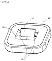
- the power base (40) of the payment terminal comprises, according to this embodiment of the invention, guiding means (41) of the payment terminal to a supply position of said payment terminal.
- the guiding means are arranged in such a way as to be inserted, or to penetrate, in means for receiving a memory card, for example a smart card, provided in an opening of the terminal of the payment terminal, because of their specific form similar to a memory card.
- a memory card for example a smart card
- These guide means are positioned in a concave part, here a hollow (43) formed in the feed base, thus allowing the terminal to reach a feed position when it is housed in the hollow of the base, position in which it is stably maintained by the cooperation of the recess and guide means.
- the means for receiving a memory card are efficiently exploited. Indeed, the same means allow, firstly, classically, the insertion of a memory card, and secondly, according to the invention, the electrical charging of the device, without it being necessary to provide a specific socket on this device.
- the electrical contacts for charging are arranged so as not to interfere with the use of the memory card, and for example on the sides of the receiving means.
- the guiding means (41) comprise feed means (42), arranged to cooperate, in a feed position, with contacts of the payment terminal, enabling the connection to a power supply.
- the supply means are metal parts, positioned on each side of the guide means (41), as illustrated in FIG. figure 2 .
- the supply means on the base cooperate with contacts of the terminal, thus ensuring the charging of the terminal battery.
- the contacts (50) are positioned on either side of the input of the smart card reader (51) of the terminal, thus enabling the terminal to be powered when the latter is in the position of feeding on the base.
- the guide means (41) of the base being inserted into the card reader (51) of the terminal, the terminal resting on the recess (43) of the base, the feed means (42) of the base co with the contacts of the terminal (50). These contacts are further used to discharge static electricity from the terminal.
- a particular embodiment of the invention is now described based on a new type of electronic payment terminal based on the physical pairing of a payment device with a communication terminal, such as a "smartphone", to form a payment terminal.
- This new type of terminal aims to overcome the disadvantages of the prior art and in particular allows not to use a dedicated telephone line to make a connection to the communication network and servers such as authorization servers or bank servers .
- the most recent terminals are connected to cash registers and / or computers via a communication network.
- Such connections may be wired, for example Ethernet, or wireless.
- These connections make it possible, for example, to connect to an authentication server or to a banking server in order to obtain debit authorization.
- the payment terminal uses a means of connection.
- One of these means is to use a wireless communication network, for example GPRS (General Packet Radio Service).
- the payment terminal is then equipped with a SIM card ( Subscriber Identity Module ). This is a chip containing a microcontroller and memory. This SIM card is associated with a telephone subscription (of data transmission type) which must be subscribed by the merchant.
- the implementation of the communication functionalities is attributed to the terminal.
- the terminal In addition to the fact that this type of subscription is relatively expensive, the implementation of the communication functionalities is attributed to the terminal.
- the terminal In addition to the payment functions, the terminal must manage communication functions, which are not naturally the functions expected of a payment terminal.
- WiFi Wireless Fidelity
- the merchant is no longer obliged to subscribe to a particular subscription.
- the payment terminal can connect to the merchant WiFi network and access, as in a wired connection, to the bank servers.
- the use of the terminal is then limited to the coverage area of the WiFi network, which is not suitable for nomadic use (for example a doctor visiting his patients).
- the electronic payment terminal according to this embodiment of the invention does not have these disadvantages of the prior art.
- the invention according to this embodiment relates more particularly to a payment terminal which is in the form of a device called "payment" which is physically paired with a communication terminal.
- the communication terminal to which the payment device is paired is a mobile terminal, commonly called “smartphone” (English), that is to say a mobile phone also having functions of a digital assistant Personnel (PDA).
- a mobile terminal commonly called “smartphone” (English)
- PDA digital assistant Personnel
- the invention overcomes the disadvantages of the prior art and in particular allows not to use a dedicated telephone line to make a connection to the communication network and servers such as authorization servers or bank servers .
- the payment terminal according to the invention has an asymmetrical structure, and therefore a particular positioning of its supply means.
- the power supply base according to the invention makes it possible to take account of the particular asymmetrical structure of the payment terminal according to the invention.
- the payment device is physically paired with the communication terminal via a particular pairing structure, called a modular interface.
- a particular pairing structure called a modular interface.
- this modular interface is attached to a back side of the payment device.
- This structure is removable, according to a particular embodiment of the invention, by implementing a particular kinematic.
- This modular interface allows to insert and retain the communication terminal in a housing provided for this purpose.
- a pairing device also called electronic connection card, for making a physical connection between the payment device and the communication terminal.
- This modular interface comprises other elements, which, according to the invention, provide a secure use of the payment terminal formed by the payment device and the communication terminal.
- the payment terminal (10) comprises two general components that are the payment device (20) and the communication terminal (30).
- the payment device (20) comprises a front face, visible on the Figure 1B , presenting a keyboard for entering information (21-1) and a display screen (21-2) of the information entered.
- the payment device comprises, on the rear face, visible on the figure 1D a surface (22) for attaching a modular interface (60) for pairing the communication terminal (30).
- this modular interface defines a housing (60-1) for insertion and pairing of the communication terminal (30).
- the figure 2 already described above, presents an example of a power supply base for such a payment terminal, according to one embodiment of the invention.
- the guiding means also serve as a key to the user of the terminal and allow him to properly position the payment terminal on the base, so as to ensure the proper operation of the power supply.
- the figure 3 also described above, illustrates an example of contacts for the supply of such a payment terminal comprising a pairing of two devices.
Description
- La présente invention se rapporte au domaine des terminaux de paiement électroniques. Plus particulièrement, la présente invention se rapporte à une base d'alimentation pour terminal de paiement électronique.
- A l'heure actuelle, les terminaux de paiement sont majoritairement utilisés pour permettre le règlement des achats de biens et de services au sein des points de vente. Ces terminaux comprennent généralement un lecteur de carte à puce et un lecteur de carte magnétique. Ils comprennent également un écran, permettant notamment de visualiser les montants des transactions et un clavier de saisie de ces mêmes montants ainsi que des codes confidentiels saisis par les clients, ou bien un écran tactile.
- Ces terminaux de paiement possèdent en général une batterie, leur permettant de fonctionner de manière autonome. Cette batterie doit être rechargée régulièrement, classiquement par l'intermédiaire d'une base d'alimentation, encore appelée socle d'alimentation, sur lequel le terminal de paiement est posé de façon à ce que les moyens d'alimentation du terminal viennent en contact avec les moyens d'alimentation de la base.
- Classiquement, une telle base d'alimentation présente des moyens de guidage du terminal de paiement vers une position d'alimentation, sous la forme de montants le long desquels le terminal doit glisser, ou sous la forme de tiges métalliques venant s'insérer dans des emplacements du terminal prévus à cet effet.
- Un inconvénient de ces différents moyens de guidage réside dans leur forme encombrante et/ou leur imprécision de guidage.
- Ainsi, il existe un besoin pour proposer une nouvelle base d'alimentation pour terminal de paiement électronique, qui soit de forme compacte et peu encombrante, tout en présentant une précision optimale de guidage du terminal de paiement électronique vers une position d'alimentation.
- Le document
US 5 933 812 décrit des terminaux de paiement adaptés à une utilisation dans un bar ou restaurant, de façon à permettre aux clients de régler leur note de façon discrète, sans se déplacer, grâce à la présence sur le terminal d'un couvercle cachant l'écran de saisie par exemple. - Le document
US 2003/178967 concerne un système comportant plusieurs équipements électroniques muni chacun d'une batterie rechargeable, connectés entre eux, dans lequel la charge de la batterie d'un premier équipement est utilisée pour le rechargement de la batterie d'un second équipement (et vice-versa). - Le document
US 2006/279251 divulgue un chargeur pour terminal mobile, comportant un berceau ajustable, permettant de positionner le terminal de façon à pouvoir visualiser les informations présentes sur l'écran du terminal lorsqu'il est installé dans le chargeur. - Ces documents ne permettent pas de résoudre le problème technique précité.
- L'invention propose donc une solution nouvelle qui ne présente pas l'ensemble de ces inconvénients de l'art antérieur, sous la forme d'une base d'alimentation pour un terminal de paiement électronique dont le boîtier présente une ouverture destinée à recevoir une carte à puce, selon les revendications 1 à 4.
- Ainsi, on exploite le même emplacement, pour la lecture d'une carte à puce et pour la charge électrique, ce qui permet d'optimiser la fabrication du dispositif, et de limiter le nombre d'ouvertures dans son boîtier.
- Selon l'invention, les moyens de guidage sont prévus pour s'insérer dans les moyens de réception d'une carte à puce du terminal de paiement, par exemple un lecteur de carte à puce dont l'entrée est située dans la tranche inférieure du terminal de paiement en position d'utilisation.
- Selon une caractéristique particulière de l'invention, les moyens de guidage de la base sont formés par une excroissance de matière de la base d'alimentation présentant une forme similaire à celle d'une carte à puce.
- Ainsi, les moyens de guidage sont formés avec la base, sans ajout d'éléments après la fabrication de la base, offrant ainsi une uniformité de la structure de la base d'alimentation.
- Par exemple, l'excroissance a la forme, c'est-à-dire l'épaisseur et/ou la largeur et/ou la hauteur, d'une carte à mémoire.
- Les moyens de guidage peuvent par exemple présenter une épaisseur identique à une carte à mémoire, mais une largeur et une hauteur moindres, de manière à offrir une meilleure compacité de la base d'alimentation.
- Selon un autre mode de réalisation de l'invention, lesdits moyens de guidage comprennent des moyens d'alimentation, agencés pour coopérer avec des contacts non affleurants dudit terminal de paiement, dans ladite position d'alimentation.
- Ainsi, selon ce mode de réalisation de l'invention, les moyens de guidage permettent également d'assurer la fonction d'alimentation du terminal de paiement.
- Par exemple, les moyens d'alimentation de la base sont formés par au moins une pièce métallique positionnée de chaque côté des moyens de guidage, chaque pièce métallique coopérant avec un contact du terminal de paiement.
- Il est à noter que les exemples et modes de réalisation dans la description ne font pas partie de l'invention mais représentent des éléments de l'état de la technique qui sont utiles à la compréhension de l'invention. En effet, l'invention est définie uniquement par les revendications.
- D'autres caractéristiques et avantages de l'invention apparaîtront plus clairement à la lecture de la description suivante d'un mode de réalisation particulier, donné à titre de simple exemple illustratif et non limitatif, et des dessins annexés, parmi lesquels :
- les
figures 1A à 1D illustrent un exemple de terminal de paiement selon un mode de réalisation de l'invention ; - la
figure 2 illustre un exemple de base d'alimentation pour un terminal de paiement tel qu'illustré enfigures 1A à 1D , selon un mode de réalisation de l'invention ; - la
figure 3 décrit un exemple de moyens d'alimentation d'un terminal de paiement tel qu'illustré enfigures 1A à 1D , selon un mode de réalisation de l'invention. - Le principe général de l'invention repose sur une base d'alimentation utilisant des moyens de réception d'une carte à mémoire dans une ouverture d'un boîtier d'un terminal de paiement électronique, permettant ainsi de guider avec précision le terminal de paiement électronique vers une position d'alimentation, tout en offrant une forme compacte de base d'alimentation.
- On présente, en relation avec la
figure 2 , un exemple de base d'alimentation pour un tel terminal de paiement, selon un mode de réalisation de l'invention. - La base d'alimentation (40) du terminal de paiement comprend, selon ce mode de réalisation de l'invention, des moyens de guidage (41) du terminal de paiement vers une position d'alimentation dudit terminal de paiement.
- Comme illustré sur la
figure 2 , les moyens de guidage sont agencés de manière à s'insérer, ou pénétrer, dans des moyens de réception d'une carte à mémoire, par exemple une carte à puce, prévus dans une ouverture du boîtier du terminal de paiement, du fait de leur forme spécifique similaire à une carte à mémoire. - Ces moyens de guidage sont positionnés dans une partie concave, ici un creux (43) formé dans la base d'alimentation, permettant ainsi au terminal d'atteindre une position d'alimentation lorsqu'il est logé dans le creux de la base, position dans lequel il est maintenu de façon stable, par la coopération du creux et des moyens de guidage.
- On exploite par ailleurs, de façon efficace, les moyens de réception d'une carte à mémoire. En effet, les mêmes moyens permettent, d'une part, classiquement, l'insertion d'une carte à mémoire, et d'autre part, selon l'invention, le chargement électrique du dispositif, sans qu'il soit nécessaire de prévoir une prise femelle spécifique sur ce dispositif. Les contacts électriques permettant la charge sont placés de façon à ne pas interférer avec l'utilisation de la carte à mémoire, et par exemple sur les côtés des moyens de réception.
- Par ailleurs, selon ce mode de réalisation de l'invention, les moyens de guidage (41) comprennent des moyens d'alimentation (42), agencés pour coopérer, dans une position d'alimentation, avec des contacts du terminal de paiement, permettant la connexion à une alimentation.
- Par exemple, les moyens d'alimentation sont des pièces métalliques, positionnées de chaque côté des moyens de guidage (41), comme illustré sur la
figure 2 . - Ainsi, lorsque le terminal est en position d'alimentation, c'est-à-dire lorsque les moyens de guidage (41) sont insérés dans des moyens de réception d'une carte à puce du terminal et que le terminal est logé dans le creux (43) de la base, les moyens d'alimentation sur la base coopèrent avec des contacts du terminal, assurant ainsi la charge de la batterie du terminal.
- Ces contacts internes (50) du terminal de paiement sont illustrés en
figure 3 . - Selon ce mode de réalisation, les contacts (50) sont positionnés de part et d'autre de l'entrée du lecteur de carte à puce (51) du terminal, permettant ainsi une alimentation du terminal lorsque celui-ci est en position d'alimentation sur la base. En effet, les moyens de guidage (41) de la base étant insérés dans le lecteur de carte (51) du terminal, le terminal reposant sur le creux (43) de la base, les moyens d'alimentation (42) de la base coopèrent avec les contacts du terminal (50). Ces contacts sont en outre utilisés pour décharger l'électricité statique du terminal.
- Il est à noter que le positionnement des contacts (50) du terminal de paiement à l'intérieur de celui-ci, et non pas, comme classiquement dans l'art antérieur, affleurant à l'extérieur du terminal, permet d'assurer une bonne sécurité en termes d'électricité statique, les contacts étant hors d'atteinte de l'utilisateur du terminal de paiement en mode normal d'utilisation. Les contraintes en termes de décharge d'électricité statique (en anglais « ESD » pour « ElectroStatic Discharge ») sont donc moins strictes du fait du positionnement non affleurant de ces contacts. En outre, ces contacts ne sont pas visibles ni aisément accessibles, de l'extérieur, ce qui évite de mauvaises manipulations, ou des manipulations frauduleuses.
- On décrit maintenant un mode de réalisation particulier de l'invention basé sur un nouveau type de terminal de paiement électronique reposant sur l'appairage physique d'un dispositif de paiement à un terminal de communication, tel qu'un « smartphone », pour former un terminal de paiement.
- Ce nouveau type de terminal vise à pallier les inconvénients de l'art antérieur et notamment permet de ne pas avoir recours à une ligne téléphonique dédiée pour réaliser une connexion au réseau de communication et aux serveurs tels que des serveurs d'autorisation ou des serveurs bancaires.
- En effet, les terminaux les plus récents sont connectés à des caisses enregistreuses et/ou à des ordinateurs par l'intermédiaire d'un réseau de communication. De telles connexions peuvent être filaires, par exemple de type Ethernet, ou sans fil. Ces connexions permettent par exemple de se connecter à un serveur d'authentification ou à un serveur bancaire en vue de l'obtention d'autorisation de débit.
- Pour pouvoir communiquer avec l'extérieur, et notamment avec des serveurs bancaires, le terminal de paiement utilise donc un moyen de connexion. L'un de ces moyens consiste à utiliser un réseau de communication sans fil, par exemple GPRS (de l'anglais « General Packet Radio Service »). Le terminal de paiement est alors muni d'une carte SIM (de l'anglais « Subscriber Identity Module »). Il s'agit d'une puce contenant un microcontrôleur et de la mémoire. Cette carte SIM est associée à un abonnement téléphonique (de type transmission de données) qui doit être souscrit par le commerçant.
- Outre le fait que ce type d'abonnement est relativement onéreux, la mise en oeuvre des fonctionnalités de communication est attribuée au terminal. Ainsi, en plus des fonctions de paiement, le terminal doit gérer des fonctions de communication, qui ne sont pas naturellement les fonctions que l'on attend d'un terminal de paiement.
- Pour pallier le problème de coût de l'abonnement associé à la communication GPRS notamment, de nouveaux types de terminaux communiquent par l'intermédiaire d'un réseau de type « WiFi » (de l'anglais pour « Wireless Fidelity ») par exemple. Le commerçant n'est alors plus obligé de souscrire un abonnement particulier. Le terminal de paiement peut se connecter au réseau WiFi du commerçant et accéder, comme dans une connexion filaire, aux serveurs bancaires. Cependant, l'usage du terminal est alors limité à la zone de couverture du réseau WiFi, ce qui ne convient pas à une utilisation nomade (par exemple un médecin en visite chez ses patients).
- Ainsi, il existe un besoin pour proposer un terminal de paiement qui puisse être utilisé par les commerçants nomades, donc en utilisant un réseau de communication sans fil de type GPRS/UMTS, tout en minimisant les coûts de mise en oeuvre d'un tel terminal de paiement.
- Le terminal de paiement électronique selon ce mode de réalisation de l'invention ne présente pas ces inconvénients de l'art antérieur.
- L'invention selon ce mode de réalisation se rapporte plus particulièrement à un terminal de paiement qui se présente sous la forme d'un dispositif dit « de paiement » qui est physiquement appairé à un terminal de communication.
- Plus particulièrement, le terminal de communication auquel le dispositif de paiement est appairé est un terminal mobile, communément appelé « smartphone » (de l'anglais), c'est-à-dire un téléphone mobile disposant aussi de fonctions d'un assistant numérique personnel (PDA).
- Ainsi, l'invention permet de pallier les inconvénients de l'art antérieur et notamment permet de ne pas avoir recours à une ligne téléphonique dédiée pour réaliser une connexion au réseau de communication et aux serveurs tels que des serveurs d'autorisation ou des serveurs bancaires.
- Par ailleurs, du fait de l'appairage de ces deux dispositifs, dont notamment l'épaisseur n'est pas identique, le terminal de paiement selon l'invention présente une structure asymétrique, et donc un positionnement particulier de ses moyens d'alimentation.
- La base d'alimentation selon l'invention permet de tenir compte de la structure particulière asymétrique du terminal de paiement selon l'invention.
- Plus particulièrement, dans ce mode de réalisation de l'invention, le dispositif de paiement est physiquement appairé avec le terminal de communication par l'intermédiaire d'une structure d'appairage particulière, appelée interface modulaire. Lorsqu'elle est utilisée, cette interface modulaire est fixée sur une face arrière du dispositif de paiement. Cette structure est démontable, selon un mode de réalisation particulier de l'invention, en mettant en oeuvre une cinématique particulière.
- Cette interface modulaire, selon l'invention, permet d'insérer et de retenir le terminal de communication dans un logement prévu à cet effet. Parmi les éléments de cette interface modulaire, selon l'invention, on distingue notamment un dispositif d'appairage, encore appelé carte électronique de connexion, permettant de réaliser une connexion physique entre le dispositif de paiement et le terminal de communication.
- Cette interface modulaire comprend d'autres éléments, qui, selon l'invention, permettent d'assurer une sécurité d'usage du terminal de paiement formé du dispositif de paiement et du terminal de communication.
- Plus particulièrement, le terminal de paiement objet de l'invention est décrit en relation avec les
figures 1A à 1D . - Le terminal de paiement (10) comprend deux composants généraux que sont le dispositif de paiement (20) et le terminal de communication (30).
- Comme illustré dans un mode de réalisation illustratif et non limitatif de l'invention, le dispositif de paiement (20) comprend une face avant, visible sur la
figure 1B , présentant un clavier pour la saisie d'information (21-1) et un écran de visualisation (21-2) des informations saisies. Le dispositif de paiement comprend, en face arrière, visible sur lafigure 1D , une surface (22) permettant la fixation d'une interface modulaire (60) pour l'appairage du terminal de communication (30). - Plus particulièrement, cette interface modulaire définit un logement (60-1) d'insertion et d'appairage du terminal de communication (30).
- La
figure 2 , déjà décrite ci-dessus, présente un exemple de base d'alimentation pour un tel terminal de paiement, selon un mode de réalisation de l'invention. - Toutes les caractéristiques de l'invention décrites ci-dessus en relation avec la
figure 2 s'appliquent également à ce mode de réalisation, et ne sont pas reprises ici. - Par ailleurs, on peut voir sur cette
figure 2 que les moyens de guidage (41) ne sont pas positionnés de manière symétrique dans le creux (43), permettant ainsi de tenir compte de la structure asymétrique spécifique du terminal de paiement selon l'invention. - Ainsi, les moyens de guidage servent également de détrompeur à l'utilisateur du terminal et lui permettent de positionner correctement le terminal de paiement sur la base, de façon à assurer le bon fonctionnement de l'alimentation.
- La
figure 3 , également décrite ci-dessus, illustre un exemple de contacts pour l'alimentation d'un tel terminal de paiement comprenant un appairage de deux dispositifs.
Claims (4)
- Base d'alimentation (40) pour un terminal de paiement (10) dont le boîtier présente une entrée d'un lecteur de carte à puce, ladite entrée étant adaptée pour recevoir une carte à puce, ladite base d'alimentation comprenant des moyens de guidage (41) dudit terminal de paiement vers une position d'alimentation dudit terminal de paiement, lesdits moyens de guidage comprenant au moins une portion de guidage dont la forme est apte à permettre son insertion dans ladite entrée dudit lecteur de carte à puce dudit terminal de paiement (10).
- Base d'alimentation selon la revendication 1, caractérisée en ce que ladite portion de guidage (41) comprend une excroissance s'étendant à partir de ladite base d'alimentation présentant une forme représentative d'une carte à puce.
- Base d'alimentation selon la revendication 1, caractérisée en ce que lesdits moyens de guidage (41) comprennent des moyens d'alimentation (42), agencés pour coopérer avec des contacts non affleurants dudit terminal de paiement (10), dans ladite position d'alimentation.
- Base d'alimentation selon la revendication 3, caractérisée en ce que lesdits moyens d'alimentation (42) comprennent au moins une pièce métallique positionnée de chaque côté desdits moyens de guidage, chaque pièce métallique coopérant avec un contact dudit terminal de paiement (10).
Priority Applications (1)
| Application Number | Priority Date | Filing Date | Title |
|---|---|---|---|
| PL11793433T PL2649698T3 (pl) | 2010-12-07 | 2011-12-07 | Baza zasilająca dla terminala do płatności elektronicznych |
Applications Claiming Priority (3)
| Application Number | Priority Date | Filing Date | Title |
|---|---|---|---|
| FR1060206A FR2968419B1 (fr) | 2010-12-07 | 2010-12-07 | Base d'alimentation pour terminal de paiement electronique et terminal de paiement electronique. |
| FR1060204A FR2968433B1 (fr) | 2010-12-07 | 2010-12-07 | Dispositif de paiement electronique apte a recevoir et maintenir un telephone portable. |
| PCT/EP2011/072003 WO2012076569A2 (fr) | 2010-12-07 | 2011-12-07 | Base d'alimentation pour terminal de paiement électronique et terminal de paiement électronique. |
Publications (2)
| Publication Number | Publication Date |
|---|---|
| EP2649698A2 EP2649698A2 (fr) | 2013-10-16 |
| EP2649698B1 true EP2649698B1 (fr) | 2019-03-27 |
Family
ID=45217560
Family Applications (1)
| Application Number | Title | Priority Date | Filing Date |
|---|---|---|---|
| EP11793433.1A Active EP2649698B1 (fr) | 2010-12-07 | 2011-12-07 | Base d'alimentation pour un terminal de paiement électronique |
Country Status (8)
| Country | Link |
|---|---|
| US (1) | US9213369B2 (fr) |
| EP (1) | EP2649698B1 (fr) |
| AU (1) | AU2011340557B2 (fr) |
| BR (1) | BR112013014114A2 (fr) |
| CA (1) | CA2819863C (fr) |
| ES (1) | ES2732294T3 (fr) |
| PL (1) | PL2649698T3 (fr) |
| WO (1) | WO2012076569A2 (fr) |
Families Citing this family (1)
| Publication number | Priority date | Publication date | Assignee | Title |
|---|---|---|---|---|
| WO2023172286A1 (fr) * | 2022-03-10 | 2023-09-14 | Qorum, Inc. | Système de traitement de paiement mobile portatif et boîtier |
Family Cites Families (14)
| Publication number | Priority date | Publication date | Assignee | Title |
|---|---|---|---|---|
| US5109540A (en) | 1989-05-01 | 1992-04-28 | Motorola, Inc. | Radio and electronic card assembly |
| DE69324445T2 (de) | 1992-11-27 | 1999-09-30 | Denso Corp | Tragbares elektronisches Gerät |
| US5933812A (en) * | 1995-04-12 | 1999-08-03 | Verifone Inc. | Portable transaction terminal system |
| US6653813B2 (en) * | 2002-03-21 | 2003-11-25 | Thomson Licensing, S.A. | Apparatus and method for the power management of operatively connected modular devices |
| US20040104268A1 (en) | 2002-07-30 | 2004-06-03 | Bailey Kenneth Stephen | Plug in credit card reader module for wireless cellular phone verifications |
| CN101588397B (zh) | 2004-03-05 | 2011-11-16 | 日本电气株式会社 | 便携终端用底座装置 |
| US7240836B2 (en) | 2004-04-23 | 2007-07-10 | Virtual Fonlink, Inc. | Enhanced system and method for wireless transactions |
| US7309012B2 (en) | 2004-09-07 | 2007-12-18 | Semtek Innovative Solutions, Inc. | Secure magnetic stripe reader for handheld computing and method of using same |
| US8229501B2 (en) * | 2004-09-09 | 2012-07-24 | Dana Innovations | Computer wall docking station |
| US20060178967A1 (en) | 2005-02-04 | 2006-08-10 | Searete Llc | Disposition of proprietary virtual rights |
| US20060279251A1 (en) | 2005-06-10 | 2006-12-14 | Guyot Nicolas E | Adjustable charger |
| US7580255B2 (en) * | 2005-08-24 | 2009-08-25 | Apple Inc. | Docking station for hand held electronic devices |
| US8559171B2 (en) * | 2008-02-22 | 2013-10-15 | Hewlett-Packard Development Company, L.P. | Docking station, and associated methodology, for a mini personal computer |
| US7751185B2 (en) * | 2008-09-16 | 2010-07-06 | Amtek System Co., Ltd. | Docking station applied to a portable electronic device |
-
2011
- 2011-12-07 AU AU2011340557A patent/AU2011340557B2/en not_active Ceased
- 2011-12-07 US US13/992,360 patent/US9213369B2/en active Active
- 2011-12-07 WO PCT/EP2011/072003 patent/WO2012076569A2/fr active Application Filing
- 2011-12-07 PL PL11793433T patent/PL2649698T3/pl unknown
- 2011-12-07 CA CA2819863A patent/CA2819863C/fr active Active
- 2011-12-07 ES ES11793433T patent/ES2732294T3/es active Active
- 2011-12-07 EP EP11793433.1A patent/EP2649698B1/fr active Active
- 2011-12-07 BR BR112013014114A patent/BR112013014114A2/pt not_active Application Discontinuation
Non-Patent Citations (1)
| Title |
|---|
| None * |
Also Published As
| Publication number | Publication date |
|---|---|
| WO2012076569A2 (fr) | 2012-06-14 |
| CA2819863A1 (fr) | 2012-06-14 |
| AU2011340557A1 (en) | 2013-07-18 |
| US20140321047A1 (en) | 2014-10-30 |
| BR112013014114A2 (pt) | 2016-09-20 |
| US9213369B2 (en) | 2015-12-15 |
| WO2012076569A3 (fr) | 2012-08-09 |
| AU2011340557B2 (en) | 2016-03-10 |
| PL2649698T3 (pl) | 2019-09-30 |
| CA2819863C (fr) | 2020-02-04 |
| EP2649698A2 (fr) | 2013-10-16 |
| ES2732294T3 (es) | 2019-11-21 |
Similar Documents
| Publication | Publication Date | Title |
|---|---|---|
| WO2008003586A1 (fr) | Boitier pour clef electronique et systeme comportant un tel boitier | |
| FR2910746A1 (fr) | Interface de communication radiofrequence locale entre un telephone mobile et un lecteur sans contact | |
| EP0840247B1 (fr) | Modem radio équipé d'un lecteur de carte à mémoire | |
| WO2012076573A1 (fr) | Dispositif de paiement électronique apte à recevoir et maintenir un téléphone portable | |
| WO2009083658A1 (fr) | Distribution de titres électroniques par radiofréquence | |
| WO2003077163A2 (fr) | Procédé de gestion d'informations stockées sur une carte a puce lisible par un téléphone mobile | |
| EP2649698B1 (fr) | Base d'alimentation pour un terminal de paiement électronique | |
| EP2649699B1 (fr) | Procédé de gestion du niveau de charge d'au moins deux batteries, dispositif et programme d'ordinateur correspondants | |
| EP3320503A1 (fr) | Dispositif périphérique actif et terminal de paiement électronique | |
| EP2649777B1 (fr) | Dispositif de paiement électronique | |
| CA2984556A1 (fr) | Terminal de paiement integrant des moyens de communication sans fil | |
| EP3543894A1 (fr) | Socle d'accueil d'un terminal mobile et terminal mobile correspondant | |
| FR2968419A1 (fr) | Base d'alimentation pour terminal de paiement electronique et terminal de paiement electronique. | |
| WO2019016470A1 (fr) | Procédé et système de gestion d'un paiement par porte-monnaie électronique | |
| EP2649779B1 (fr) | Interface modulaire comprise dans un terminal de paiement électronique, avec articulation d'un couvercle par translation et rotation. | |
| FR2903545A1 (fr) | Distribution de titres electroniques par radiofrequence | |
| WO2012076498A1 (fr) | Terminal de paiement comprenant un dispositif de paiement et une interface modulaire formant capot ou étui pour appairer un terminal de communication | |
| FR2968478A1 (fr) | Procede de gestion du niveau de charge d'au moins deux batteries, dispositif et programme d'ordinateur correspondants. | |
| FR2968434A1 (fr) | Dispositif de paiement electronique. | |
| FR2968492A1 (fr) | Terminal de paiement comprenant un dispositif de paiement et une interface modulaire formant capot ou etui pour appairer un terminal de communication. | |
| FR2968491A1 (fr) | Interface modulaire comprise dans un terminal de paiement electronique, avec articulation d'un couvercle par translation et rotation. |
Legal Events
| Date | Code | Title | Description |
|---|---|---|---|
| PUAI | Public reference made under article 153(3) epc to a published international application that has entered the european phase |
Free format text: ORIGINAL CODE: 0009012 |
|
| 17P | Request for examination filed |
Effective date: 20130624 |
|
| AK | Designated contracting states |
Kind code of ref document: A2 Designated state(s): AL AT BE BG CH CY CZ DE DK EE ES FI FR GB GR HR HU IE IS IT LI LT LU LV MC MK MT NL NO PL PT RO RS SE SI SK SM TR |
|
| DAX | Request for extension of the european patent (deleted) | ||
| RAP1 | Party data changed (applicant data changed or rights of an application transferred) |
Owner name: INGENICO GROUP |
|
| STAA | Information on the status of an ep patent application or granted ep patent |
Free format text: STATUS: EXAMINATION IS IN PROGRESS |
|
| 17Q | First examination report despatched |
Effective date: 20180523 |
|
| GRAP | Despatch of communication of intention to grant a patent |
Free format text: ORIGINAL CODE: EPIDOSNIGR1 |
|
| STAA | Information on the status of an ep patent application or granted ep patent |
Free format text: STATUS: GRANT OF PATENT IS INTENDED |
|
| RIC1 | Information provided on ipc code assigned before grant |
Ipc: G06F 1/16 20060101ALI20181002BHEP Ipc: H02J 7/00 20060101AFI20181002BHEP Ipc: H04M 1/04 20060101ALI20181002BHEP |
|
| INTG | Intention to grant announced |
Effective date: 20181025 |
|
| GRAS | Grant fee paid |
Free format text: ORIGINAL CODE: EPIDOSNIGR3 |
|
| GRAA | (expected) grant |
Free format text: ORIGINAL CODE: 0009210 |
|
| STAA | Information on the status of an ep patent application or granted ep patent |
Free format text: STATUS: THE PATENT HAS BEEN GRANTED |
|
| AK | Designated contracting states |
Kind code of ref document: B1 Designated state(s): AL AT BE BG CH CY CZ DE DK EE ES FI FR GB GR HR HU IE IS IT LI LT LU LV MC MK MT NL NO PL PT RO RS SE SI SK SM TR |
|
| REG | Reference to a national code |
Ref country code: GB Ref legal event code: FG4D Free format text: NOT ENGLISH |
|
| REG | Reference to a national code |
Ref country code: CH Ref legal event code: EP |
|
| REG | Reference to a national code |
Ref country code: AT Ref legal event code: REF Ref document number: 1114187 Country of ref document: AT Kind code of ref document: T Effective date: 20190415 |
|
| REG | Reference to a national code |
Ref country code: IE Ref legal event code: FG4D Free format text: LANGUAGE OF EP DOCUMENT: FRENCH |
|
| REG | Reference to a national code |
Ref country code: DE Ref legal event code: R096 Ref document number: 602011057570 Country of ref document: DE |
|
| PG25 | Lapsed in a contracting state [announced via postgrant information from national office to epo] |
Ref country code: NO Free format text: LAPSE BECAUSE OF FAILURE TO SUBMIT A TRANSLATION OF THE DESCRIPTION OR TO PAY THE FEE WITHIN THE PRESCRIBED TIME-LIMIT Effective date: 20190627 Ref country code: FI Free format text: LAPSE BECAUSE OF FAILURE TO SUBMIT A TRANSLATION OF THE DESCRIPTION OR TO PAY THE FEE WITHIN THE PRESCRIBED TIME-LIMIT Effective date: 20190327 Ref country code: SE Free format text: LAPSE BECAUSE OF FAILURE TO SUBMIT A TRANSLATION OF THE DESCRIPTION OR TO PAY THE FEE WITHIN THE PRESCRIBED TIME-LIMIT Effective date: 20190327 Ref country code: LT Free format text: LAPSE BECAUSE OF FAILURE TO SUBMIT A TRANSLATION OF THE DESCRIPTION OR TO PAY THE FEE WITHIN THE PRESCRIBED TIME-LIMIT Effective date: 20190327 |
|
| REG | Reference to a national code |
Ref country code: NL Ref legal event code: MP Effective date: 20190327 |
|
| PG25 | Lapsed in a contracting state [announced via postgrant information from national office to epo] |
Ref country code: HR Free format text: LAPSE BECAUSE OF FAILURE TO SUBMIT A TRANSLATION OF THE DESCRIPTION OR TO PAY THE FEE WITHIN THE PRESCRIBED TIME-LIMIT Effective date: 20190327 Ref country code: NL Free format text: LAPSE BECAUSE OF FAILURE TO SUBMIT A TRANSLATION OF THE DESCRIPTION OR TO PAY THE FEE WITHIN THE PRESCRIBED TIME-LIMIT Effective date: 20190327 Ref country code: LV Free format text: LAPSE BECAUSE OF FAILURE TO SUBMIT A TRANSLATION OF THE DESCRIPTION OR TO PAY THE FEE WITHIN THE PRESCRIBED TIME-LIMIT Effective date: 20190327 Ref country code: BG Free format text: LAPSE BECAUSE OF FAILURE TO SUBMIT A TRANSLATION OF THE DESCRIPTION OR TO PAY THE FEE WITHIN THE PRESCRIBED TIME-LIMIT Effective date: 20190627 Ref country code: RS Free format text: LAPSE BECAUSE OF FAILURE TO SUBMIT A TRANSLATION OF THE DESCRIPTION OR TO PAY THE FEE WITHIN THE PRESCRIBED TIME-LIMIT Effective date: 20190327 |
|
| REG | Reference to a national code |
Ref country code: AT Ref legal event code: MK05 Ref document number: 1114187 Country of ref document: AT Kind code of ref document: T Effective date: 20190327 |
|
| REG | Reference to a national code |
Ref country code: GR Ref legal event code: EP Ref document number: 20190401725 Country of ref document: GR Effective date: 20190906 |
|
| PG25 | Lapsed in a contracting state [announced via postgrant information from national office to epo] |
Ref country code: EE Free format text: LAPSE BECAUSE OF FAILURE TO SUBMIT A TRANSLATION OF THE DESCRIPTION OR TO PAY THE FEE WITHIN THE PRESCRIBED TIME-LIMIT Effective date: 20190327 Ref country code: RO Free format text: LAPSE BECAUSE OF FAILURE TO SUBMIT A TRANSLATION OF THE DESCRIPTION OR TO PAY THE FEE WITHIN THE PRESCRIBED TIME-LIMIT Effective date: 20190327 Ref country code: AL Free format text: LAPSE BECAUSE OF FAILURE TO SUBMIT A TRANSLATION OF THE DESCRIPTION OR TO PAY THE FEE WITHIN THE PRESCRIBED TIME-LIMIT Effective date: 20190327 Ref country code: CZ Free format text: LAPSE BECAUSE OF FAILURE TO SUBMIT A TRANSLATION OF THE DESCRIPTION OR TO PAY THE FEE WITHIN THE PRESCRIBED TIME-LIMIT Effective date: 20190327 Ref country code: SK Free format text: LAPSE BECAUSE OF FAILURE TO SUBMIT A TRANSLATION OF THE DESCRIPTION OR TO PAY THE FEE WITHIN THE PRESCRIBED TIME-LIMIT Effective date: 20190327 Ref country code: PT Free format text: LAPSE BECAUSE OF FAILURE TO SUBMIT A TRANSLATION OF THE DESCRIPTION OR TO PAY THE FEE WITHIN THE PRESCRIBED TIME-LIMIT Effective date: 20190727 |
|
| REG | Reference to a national code |
Ref country code: ES Ref legal event code: FG2A Ref document number: 2732294 Country of ref document: ES Kind code of ref document: T3 Effective date: 20191121 |
|
| PG25 | Lapsed in a contracting state [announced via postgrant information from national office to epo] |
Ref country code: SM Free format text: LAPSE BECAUSE OF FAILURE TO SUBMIT A TRANSLATION OF THE DESCRIPTION OR TO PAY THE FEE WITHIN THE PRESCRIBED TIME-LIMIT Effective date: 20190327 |
|
| PG25 | Lapsed in a contracting state [announced via postgrant information from national office to epo] |
Ref country code: AT Free format text: LAPSE BECAUSE OF FAILURE TO SUBMIT A TRANSLATION OF THE DESCRIPTION OR TO PAY THE FEE WITHIN THE PRESCRIBED TIME-LIMIT Effective date: 20190327 Ref country code: IS Free format text: LAPSE BECAUSE OF FAILURE TO SUBMIT A TRANSLATION OF THE DESCRIPTION OR TO PAY THE FEE WITHIN THE PRESCRIBED TIME-LIMIT Effective date: 20190727 |
|
| REG | Reference to a national code |
Ref country code: DE Ref legal event code: R097 Ref document number: 602011057570 Country of ref document: DE |
|
| PG25 | Lapsed in a contracting state [announced via postgrant information from national office to epo] |
Ref country code: DK Free format text: LAPSE BECAUSE OF FAILURE TO SUBMIT A TRANSLATION OF THE DESCRIPTION OR TO PAY THE FEE WITHIN THE PRESCRIBED TIME-LIMIT Effective date: 20190327 |
|
| PLBE | No opposition filed within time limit |
Free format text: ORIGINAL CODE: 0009261 |
|
| STAA | Information on the status of an ep patent application or granted ep patent |
Free format text: STATUS: NO OPPOSITION FILED WITHIN TIME LIMIT |
|
| PG25 | Lapsed in a contracting state [announced via postgrant information from national office to epo] |
Ref country code: SI Free format text: LAPSE BECAUSE OF FAILURE TO SUBMIT A TRANSLATION OF THE DESCRIPTION OR TO PAY THE FEE WITHIN THE PRESCRIBED TIME-LIMIT Effective date: 20190327 |
|
| 26N | No opposition filed |
Effective date: 20200103 |
|
| PG25 | Lapsed in a contracting state [announced via postgrant information from national office to epo] |
Ref country code: TR Free format text: LAPSE BECAUSE OF FAILURE TO SUBMIT A TRANSLATION OF THE DESCRIPTION OR TO PAY THE FEE WITHIN THE PRESCRIBED TIME-LIMIT Effective date: 20190327 |
|
| REG | Reference to a national code |
Ref country code: CH Ref legal event code: PL |
|
| REG | Reference to a national code |
Ref country code: BE Ref legal event code: MM Effective date: 20191231 |
|
| PG25 | Lapsed in a contracting state [announced via postgrant information from national office to epo] |
Ref country code: MC Free format text: LAPSE BECAUSE OF FAILURE TO SUBMIT A TRANSLATION OF THE DESCRIPTION OR TO PAY THE FEE WITHIN THE PRESCRIBED TIME-LIMIT Effective date: 20190327 |
|
| PG25 | Lapsed in a contracting state [announced via postgrant information from national office to epo] |
Ref country code: IE Free format text: LAPSE BECAUSE OF NON-PAYMENT OF DUE FEES Effective date: 20191207 Ref country code: LU Free format text: LAPSE BECAUSE OF NON-PAYMENT OF DUE FEES Effective date: 20191207 |
|
| PG25 | Lapsed in a contracting state [announced via postgrant information from national office to epo] |
Ref country code: LI Free format text: LAPSE BECAUSE OF NON-PAYMENT OF DUE FEES Effective date: 20191231 Ref country code: CH Free format text: LAPSE BECAUSE OF NON-PAYMENT OF DUE FEES Effective date: 20191231 Ref country code: BE Free format text: LAPSE BECAUSE OF NON-PAYMENT OF DUE FEES Effective date: 20191231 |
|
| PG25 | Lapsed in a contracting state [announced via postgrant information from national office to epo] |
Ref country code: CY Free format text: LAPSE BECAUSE OF FAILURE TO SUBMIT A TRANSLATION OF THE DESCRIPTION OR TO PAY THE FEE WITHIN THE PRESCRIBED TIME-LIMIT Effective date: 20190327 |
|
| PG25 | Lapsed in a contracting state [announced via postgrant information from national office to epo] |
Ref country code: MT Free format text: LAPSE BECAUSE OF FAILURE TO SUBMIT A TRANSLATION OF THE DESCRIPTION OR TO PAY THE FEE WITHIN THE PRESCRIBED TIME-LIMIT Effective date: 20190327 Ref country code: HU Free format text: LAPSE BECAUSE OF FAILURE TO SUBMIT A TRANSLATION OF THE DESCRIPTION OR TO PAY THE FEE WITHIN THE PRESCRIBED TIME-LIMIT; INVALID AB INITIO Effective date: 20111207 |
|
| REG | Reference to a national code |
Ref country code: GB Ref legal event code: 732E Free format text: REGISTERED BETWEEN 20220127 AND 20220202 |
|
| PG25 | Lapsed in a contracting state [announced via postgrant information from national office to epo] |
Ref country code: MK Free format text: LAPSE BECAUSE OF FAILURE TO SUBMIT A TRANSLATION OF THE DESCRIPTION OR TO PAY THE FEE WITHIN THE PRESCRIBED TIME-LIMIT Effective date: 20190327 |
|
| REG | Reference to a national code |
Ref country code: DE Ref legal event code: R081 Ref document number: 602011057570 Country of ref document: DE Owner name: BANKS AND ACQUIRES INTERNATIONAL HOLDING, FR Free format text: FORMER OWNER: INGENICO GROUP, PARIS, FR Ref country code: DE Ref legal event code: R082 Ref document number: 602011057570 Country of ref document: DE Representative=s name: STUMPF PATENTANWAELTE PARTGMBB, DE |
|
| PGFP | Annual fee paid to national office [announced via postgrant information from national office to epo] |
Ref country code: PL Payment date: 20221121 Year of fee payment: 12 |
|
| PGFP | Annual fee paid to national office [announced via postgrant information from national office to epo] |
Ref country code: ES Payment date: 20230227 Year of fee payment: 12 |
|
| PGFP | Annual fee paid to national office [announced via postgrant information from national office to epo] |
Ref country code: GR Payment date: 20231221 Year of fee payment: 13 Ref country code: GB Payment date: 20231220 Year of fee payment: 13 |
|
| PGFP | Annual fee paid to national office [announced via postgrant information from national office to epo] |
Ref country code: IT Payment date: 20231228 Year of fee payment: 13 Ref country code: FR Payment date: 20231229 Year of fee payment: 13 Ref country code: DE Payment date: 20231214 Year of fee payment: 13 |
|
| PGFP | Annual fee paid to national office [announced via postgrant information from national office to epo] |
Ref country code: PL Payment date: 20231121 Year of fee payment: 13 |