EP2648983B1 - Bottle neck structure and relative cap made of plastic material, particularly for water and beverages - Google Patents
Bottle neck structure and relative cap made of plastic material, particularly for water and beverages Download PDFInfo
- Publication number
- EP2648983B1 EP2648983B1 EP11815850.0A EP11815850A EP2648983B1 EP 2648983 B1 EP2648983 B1 EP 2648983B1 EP 11815850 A EP11815850 A EP 11815850A EP 2648983 B1 EP2648983 B1 EP 2648983B1
- Authority
- EP
- European Patent Office
- Prior art keywords
- neck
- bottle
- relief
- cap
- relative
- Prior art date
- Legal status (The legal status is an assumption and is not a legal conclusion. Google has not performed a legal analysis and makes no representation as to the accuracy of the status listed.)
- Not-in-force
Links
Images


Classifications
-
- B—PERFORMING OPERATIONS; TRANSPORTING
- B65—CONVEYING; PACKING; STORING; HANDLING THIN OR FILAMENTARY MATERIAL
- B65D—CONTAINERS FOR STORAGE OR TRANSPORT OF ARTICLES OR MATERIALS, e.g. BAGS, BARRELS, BOTTLES, BOXES, CANS, CARTONS, CRATES, DRUMS, JARS, TANKS, HOPPERS, FORWARDING CONTAINERS; ACCESSORIES, CLOSURES, OR FITTINGS THEREFOR; PACKAGING ELEMENTS; PACKAGES
- B65D41/00—Caps, e.g. crown caps or crown seals, i.e. members having parts arranged for engagement with the external periphery of a neck or wall defining a pouring opening or discharge aperture; Protective cap-like covers for closure members, e.g. decorative covers of metal foil or paper
- B65D41/32—Caps or cap-like covers with lines of weakness, tearing-strips, tags, or like opening or removal devices, e.g. to facilitate formation of pouring openings
- B65D41/34—Threaded or like caps or cap-like covers provided with tamper elements formed in, or attached to, the closure skirt
-
- B—PERFORMING OPERATIONS; TRANSPORTING
- B65—CONVEYING; PACKING; STORING; HANDLING THIN OR FILAMENTARY MATERIAL
- B65D—CONTAINERS FOR STORAGE OR TRANSPORT OF ARTICLES OR MATERIALS, e.g. BAGS, BARRELS, BOTTLES, BOXES, CANS, CARTONS, CRATES, DRUMS, JARS, TANKS, HOPPERS, FORWARDING CONTAINERS; ACCESSORIES, CLOSURES, OR FITTINGS THEREFOR; PACKAGING ELEMENTS; PACKAGES
- B65D1/00—Containers having bodies formed in one piece, e.g. by casting metallic material, by moulding plastics, by blowing vitreous material, by throwing ceramic material, by moulding pulped fibrous material, by deep-drawing operations performed on sheet material
- B65D1/02—Bottles or similar containers with necks or like restricted apertures, designed for pouring contents
- B65D1/0223—Bottles or similar containers with necks or like restricted apertures, designed for pouring contents characterised by shape
- B65D1/023—Neck construction
- B65D1/0246—Closure retaining means, e.g. beads, screw-threads
-
- B—PERFORMING OPERATIONS; TRANSPORTING
- B65—CONVEYING; PACKING; STORING; HANDLING THIN OR FILAMENTARY MATERIAL
- B65D—CONTAINERS FOR STORAGE OR TRANSPORT OF ARTICLES OR MATERIALS, e.g. BAGS, BARRELS, BOTTLES, BOXES, CANS, CARTONS, CRATES, DRUMS, JARS, TANKS, HOPPERS, FORWARDING CONTAINERS; ACCESSORIES, CLOSURES, OR FITTINGS THEREFOR; PACKAGING ELEMENTS; PACKAGES
- B65D41/00—Caps, e.g. crown caps or crown seals, i.e. members having parts arranged for engagement with the external periphery of a neck or wall defining a pouring opening or discharge aperture; Protective cap-like covers for closure members, e.g. decorative covers of metal foil or paper
- B65D41/02—Caps or cap-like covers without lines of weakness, tearing strips, tags, or like opening or removal devices
- B65D41/04—Threaded or like caps or cap-like covers secured by rotation
- B65D41/0407—Threaded or like caps or cap-like covers secured by rotation with integral sealing means
- B65D41/0414—Threaded or like caps or cap-like covers secured by rotation with integral sealing means formed by a plug, collar, flange, rib or the like contacting the internal surface of a container neck
-
- B—PERFORMING OPERATIONS; TRANSPORTING
- B65—CONVEYING; PACKING; STORING; HANDLING THIN OR FILAMENTARY MATERIAL
- B65D—CONTAINERS FOR STORAGE OR TRANSPORT OF ARTICLES OR MATERIALS, e.g. BAGS, BARRELS, BOTTLES, BOXES, CANS, CARTONS, CRATES, DRUMS, JARS, TANKS, HOPPERS, FORWARDING CONTAINERS; ACCESSORIES, CLOSURES, OR FITTINGS THEREFOR; PACKAGING ELEMENTS; PACKAGES
- B65D41/00—Caps, e.g. crown caps or crown seals, i.e. members having parts arranged for engagement with the external periphery of a neck or wall defining a pouring opening or discharge aperture; Protective cap-like covers for closure members, e.g. decorative covers of metal foil or paper
- B65D41/02—Caps or cap-like covers without lines of weakness, tearing strips, tags, or like opening or removal devices
- B65D41/04—Threaded or like caps or cap-like covers secured by rotation
- B65D41/0407—Threaded or like caps or cap-like covers secured by rotation with integral sealing means
- B65D41/0428—Threaded or like caps or cap-like covers secured by rotation with integral sealing means formed by a collar, flange, rib or the like contacting the top rim or the top edges or the external surface of a container neck
-
- B—PERFORMING OPERATIONS; TRANSPORTING
- B65—CONVEYING; PACKING; STORING; HANDLING THIN OR FILAMENTARY MATERIAL
- B65D—CONTAINERS FOR STORAGE OR TRANSPORT OF ARTICLES OR MATERIALS, e.g. BAGS, BARRELS, BOTTLES, BOXES, CANS, CARTONS, CRATES, DRUMS, JARS, TANKS, HOPPERS, FORWARDING CONTAINERS; ACCESSORIES, CLOSURES, OR FITTINGS THEREFOR; PACKAGING ELEMENTS; PACKAGES
- B65D41/00—Caps, e.g. crown caps or crown seals, i.e. members having parts arranged for engagement with the external periphery of a neck or wall defining a pouring opening or discharge aperture; Protective cap-like covers for closure members, e.g. decorative covers of metal foil or paper
- B65D41/32—Caps or cap-like covers with lines of weakness, tearing-strips, tags, or like opening or removal devices, e.g. to facilitate formation of pouring openings
- B65D41/325—Caps or cap-like covers with lines of weakness, tearing-strips, tags, or like opening or removal devices, e.g. to facilitate formation of pouring openings with integral internal sealing means
-
- B—PERFORMING OPERATIONS; TRANSPORTING
- B65—CONVEYING; PACKING; STORING; HANDLING THIN OR FILAMENTARY MATERIAL
- B65D—CONTAINERS FOR STORAGE OR TRANSPORT OF ARTICLES OR MATERIALS, e.g. BAGS, BARRELS, BOTTLES, BOXES, CANS, CARTONS, CRATES, DRUMS, JARS, TANKS, HOPPERS, FORWARDING CONTAINERS; ACCESSORIES, CLOSURES, OR FITTINGS THEREFOR; PACKAGING ELEMENTS; PACKAGES
- B65D41/00—Caps, e.g. crown caps or crown seals, i.e. members having parts arranged for engagement with the external periphery of a neck or wall defining a pouring opening or discharge aperture; Protective cap-like covers for closure members, e.g. decorative covers of metal foil or paper
- B65D41/32—Caps or cap-like covers with lines of weakness, tearing-strips, tags, or like opening or removal devices, e.g. to facilitate formation of pouring openings
- B65D41/34—Threaded or like caps or cap-like covers provided with tamper elements formed in, or attached to, the closure skirt
- B65D41/3442—Threaded or like caps or cap-like covers provided with tamper elements formed in, or attached to, the closure skirt with rigid bead or projections formed on the tamper element and coacting with bead or projections on the container
- B65D41/3447—Threaded or like caps or cap-like covers provided with tamper elements formed in, or attached to, the closure skirt with rigid bead or projections formed on the tamper element and coacting with bead or projections on the container the tamper element being integrally connected to the closure by means of bridges
Definitions
- the invention relates to a bottle neck structure and relative cap as set forth in the preamble of claim 1, the basis of which is disclosed in US 2002/0043512 A1 or in US 2009/0283494 A1 .
- the bottling companies are provided with preforms made of plastic material, usually, constituted by a tubular apically closed structure and by an open neck.
- Such preforms are subjected to blowing compressed air thereinto, once brought to a suitable degree of heat deformability, under whose constancy the tubular structure is deformed to provide the specific bottle configuration, provided by the mould in which the blowing occurs, which will then be filled by the liquid it is intended to contain.
- the capacity and shape of the tubular structure are fundamental for the final characteristics of the blown container and the respective parameters are intangible to attain containers suitable for the intended purposes, especially regarding deformation due to the pressure of the contained liquid and handling during the emptying and generally use by the end user.
- the neck remains unvaried under blowing constancy and thus also the relative thread, i.e. the entirety of the transverse reliefs which are present thereon and which guarantee the possibility of fastening to a type of cap made of plastic material, typically made of HDPE (polyethylene) or PP (polypropylene).
- HDPE polyethylene
- PP polypropylene
- the main object of the present invention is therefore, in the previously described context, to provide an innovative neck structure and relative cap for bottles made of plastic material, especially for holding water and beverages, capable of allowing lightening the weight of the structure as much as possible, without deteriorating the functionalities not even in the use for holding carbonated beverages.
- Another object of the present invention is to attain the aforementioned object through a solution concept capable of also allowing reducing the height (the axial development) of the neck.
- Another object of the present invention is to attain the aforementioned objects through a solution concept having a corollary of embodiments coherent with the aforementioned objects.
- a further object of the present invention is to attain the previous objects through a solution concept that is simple and efficient, safe during use and relatively inexpensive considering the results practically obtained therewith.
- the neck 1 of a bottle 3 made of plastic material according to the present invention particularly intended to hold water or even carbonated beverages, which will be described using the orientation terms of "high” and “low” with reference to the usual upright positioning of a container thus made on the relative base (not illustrated).
- the bottle 3 is preferably made using PET (polyethylene terephthalate) or PVC (polyvinyl chloride), while the relative cap 2 is preferably made of HDPE (polyethylene) or PP (polypropylene).
- the turns of the arched helical concavity or screw are mutually adjacent to define crests 5, as sharp as possible.
- the outer face 8 of the top annular edge 7 defining the opening 6 of the neck 1 is coplanar or, preferably, circumferentially sub-levelled with respect to the bottom of the arched helical concavity 4, with the aim of introducing the female screw 15 of the cap 2, as described hereinafter.
- annular relief 9 with straight trapezoidal section, with inclined free side 10 and facing upwards.
- the groove 12 is delimited at the lower part by a disc-shaped annular relief 13, for automatically handling the bottle 3 during filling and packaging, defined by adjacent lobes 14 (see figure 4 ).
- the cap 2 is constituted by a cylindrical plane capsule 2, with an upper closure top part 16 and annular edge 17 defining the opening, within which there projects a female screw 15 with spiral of the arc-shaped convex thread in a convex manner, accurately complementary to the concavity 4 of the helical element of the neck 1, i.e. with arcature preferably not exceeding 120° (one hundred and twenty nonagesimal degrees).
- the interior of the cap 2 is divided by a pronounced annular partition element 18, with relief 19 on the relative outer face, and by a smaller outer annular partition element 20, between which there is defined a circular interspace 21, whose bottom 22 is shaped degrading from the outer annular partition element 20 towards the annular partition element 18, for the purposes to be described hereinafter.
- beverage-breaking when the beverage is carbonated, to a point that considering greater presence of gas, i.e. a greater pressure beneath the top part 16 of the cap 2 and potentially exposed to the risk of the crests 5 being broken by the part of the female screw 15 of the cap 2, i.e. the so-called "bead-breaking", correspond to a greater radial expansion of the neck 1 and thus a greater coupling between the elements, which is opposed to the bead-breakage of the crests 5 by the female screw 15, in a manner directly proportional to the pressure of the gas.
- the firm anchoring allows reducing the screw 4 and female screw turns and thus the height of the neck 1 and the cap 2, thus allowing further saving the constituting material.
- the bottle neck structure and relative cap made of plastic materials according to the present invention may be obtained using equivalent technical and mechanical materials using actuators of any type suitable for the purpose or provided with further supplementary solutions, same case applying to all configurations of the respective components which may vary to suit the purpose.
- the annular relief underlying the arched thread on the bottle neck can be conceived notched with low relief, with the aim of attaining three objectives: facilitating the dispersion of gases released during the opening, saving weight and abutment of interior part of the security guarantee seal during unfastening, seal with notch preferably less close, so as to facilitate the breakage of the teeth that couple the seal to the cap and will have a smaller diameter due to the fact that the threads with low reliefs obtained in the neck structure reduce the diameter of the cap structure.
- the bottle neck structure and relative cap made of plastic material according to the present invention offers advantages corresponding to the attainment of the preset objects as well as other objects:
- the arched grooves create a rib on the neck structure increasing the resistance and reducing the weight.
- the polymer structure is arranged so as to be less transparent to the gases; the neck in such machining does not attain this structural advantage and remains unvaried after the injection moulding, thus attaining a lower height of the neck also attains the advantage of a lower loss of carbonation of the liquids held therein, as well as greater duration of the stocked products, with good quality advantages and thus those of the image of the product as well as good advantages in the production and distribution logistics.
- the lower height of the neck structure reduces the interior surface at contact with the liquids and subjected to the thrust stresses of the interior gases.
- the arched grooves increase the contact surface with the thread of the cap, providing a greater interaction with respect to the relief thread according to the prior art which, on the contrary, does not counter the thread, given that it is parallel and conical over the entire surface; in other words, by frontally abutting the arched female screw of the cap, the arched screw of the neck, the cap is subjected to stress in the portion of relative greater thickness, so that the stress is uniformly distributed on the structure thereof.
- the neck structure according to the invention subjects the interior of the fitting cap that surrounds it in the arched threads area a thickness that is added to the thickness of the structure on the circular wall and the arched threads being very close, i.e. the cap having a small height, smaller than that of the caps according to the prior art, they reinforce the entire circumference of the cap, creating a belt effect that is more resistant to the neck structure, to the thrust effect of the pressure of the liquids held in the bottle.
- the annular relief underlying the arched thread on the bottle neck intended to interact with the security seal, co-diametrically at the lower part associated to the cap, has a smaller diameter with respect to the homologous ones according to the prior art, in that the concave arched threads obtained in the neck structure reduce the diameter of the cap structure.
- the annular relief for automatically handling the bottle underlying the seat of the security seal, due to the lobe-like configuration thereof, has a greater reinforcement rib,, constituted by the lobes, a lower thickness and a lower inclination angle of the upper part, thus saving in terms of weight.
- the inlet edge preferably having smaller diameter and possibly greater width with respect to the concave arched threads obtained in the neck structure, facilitates the direction of insertion of the cap by the user when closing the container if the product is not finished, thus facilitating the coupling of the female screw of the cap with the concave arched threads obtained in the neck structure of the bottle.
- the inlet edge of the bottle neck preferably having a greater thickness, equivalent to the height, with respect to the concave arched threads obtained in the neck structure, distributes the overlaying weights during paletisation and storage or transport, discharging the weights on the structure of the bottle and without interfering with the edges of the grooves of the relief thread.
- the concave arched threads obtained in the neck structure constitute a concept of screw that is inexpensive to produce, hence allowing providing only one type of preform both for the carbonated products and for non-carbonated products, with a less expensive cap for the second, also attaining a considerable productive advantage of eliminating the times required to change the preform upon the variation of the liquid bottled in the automatic operation lines.
- the bottle neck structure and relative cap made of plastic material according to the present invention considering the reduction of the relative vertical development, also attains a greater reinforcement from the interior annular partition element of the cap, which reinforces the neck up to the level of the rear area at the concave arched threads obtained in the very neck structure.
Description
- The invention relates to a bottle neck structure and relative cap as set forth in the preamble of
claim 1, the basis of which is disclosed inUS 2002/0043512 A1 or inUS 2009/0283494 A1 . - As known, in the industrial manufacture of bottles made of plastic materials in general and those for mineral water and also carbonated beverages in particular, the bottling companies are provided with preforms made of plastic material, usually, constituted by a tubular apically closed structure and by an open neck.
- Such preforms are subjected to blowing compressed air thereinto, once brought to a suitable degree of heat deformability, under whose constancy the tubular structure is deformed to provide the specific bottle configuration, provided by the mould in which the blowing occurs, which will then be filled by the liquid it is intended to contain.
- In such context the capacity and shape of the tubular structure are fundamental for the final characteristics of the blown container and the respective parameters are intangible to attain containers suitable for the intended purposes, especially regarding deformation due to the pressure of the contained liquid and handling during the emptying and generally use by the end user.
- On the contrary the neck remains unvaried under blowing constancy and thus also the relative thread, i.e. the entirety of the transverse reliefs which are present thereon and which guarantee the possibility of fastening to a type of cap made of plastic material, typically made of HDPE (polyethylene) or PP (polypropylene).
- The greatest effort to improve the manufacture of the aforementioned preforms, i.e. of the bottles made of plastic material, definitely lies in saving the constituting plastic material which, even if little with reference to the single piece, allows considerably saving raw material in the large number of pieces with which it is required to be compared in the sector.
- In such context, as mentioned, there should not be a further reduction of materials from the tubular portions, which are already provided with capacity so as not to be reduced without failing to attain the relative purposes.
- Hence all technological efforts to reduce the weight are almost entirely concentrated on the portion, which is not subjected to deformation, or on the neck.
- The main object of the present invention is therefore, in the previously described context, to provide an innovative neck structure and relative cap for bottles made of plastic material, especially for holding water and beverages, capable of allowing lightening the weight of the structure as much as possible, without deteriorating the functionalities not even in the use for holding carbonated beverages.
- Another object of the present invention is to attain the aforementioned object through a solution concept capable of also allowing reducing the height (the axial development) of the neck.
- Another object of the present invention is to attain the aforementioned objects through a solution concept having a corollary of embodiments coherent with the aforementioned objects.
- A further object of the present invention is to attain the previous objects through a solution concept that is simple and efficient, safe during use and relatively inexpensive considering the results practically obtained therewith.
- These and other objects can be attained with the bottle neck structure and relative cap made of plastic material, particularly for water and beverages, according to the present invention as characterized in claim1. Further characteristics are set forth in the subclaims.
- The characteristics and advantages of the bottle neck structure and relative cap made of plastic material according to the present invention, will be more apparent from the following detailed description of a preferred but not exclusive embodiment thereof, represented solely by way of non-limiting example in four attached drawings, wherein:
-
Figure 1 shows in schematic view a section of bottle neck according to the present invention with relative cap detached in sectional view; -
Figure 2 shows in schematic view a section of bottle neck according to the present invention with relative cap attached in sectional view; -
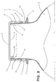
Figure 3 shows in schematic view a lateral view of bottle neck according to the present invention with relative cap attached in sectional view; -
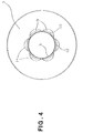
Figure 4 shows in schematic view a plan sectional view of bottle neck according to the present invention. - With reference to such figures, and in particular to
figure 1 , theneck 1 of abottle 3 made of plastic material according to the present invention, particularly intended to hold water or even carbonated beverages, which will be described using the orientation terms of "high" and "low" with reference to the usual upright positioning of a container thus made on the relative base (not illustrated). - The
bottle 3 is preferably made using PET (polyethylene terephthalate) or PVC (polyvinyl chloride), while therelative cap 2 is preferably made of HDPE (polyethylene) or PP (polypropylene). - On the
neck 1 helically develops an arc-shaped concavity 4, with arcatures preferably not exceeding 120° (one hundred and twenty nonagesimal degrees), to provide a thread or screw indicated with thesame reference number 4. - The turns of the arched helical concavity or screw are mutually adjacent to define
crests 5, as sharp as possible. - At the top part of the
bottle 3, theouter face 8 of the top annular edge 7 defining theopening 6 of theneck 1 is coplanar or, preferably, circumferentially sub-levelled with respect to the bottom of the archedhelical concavity 4, with the aim of introducing thefemale screw 15 of thecap 2, as described hereinafter. - Below the arched
helical concavity 4, orscrew 4, there is conceived anannular relief 9 with straight trapezoidal section, with inclinedfree side 10 and facing upwards. - Below the trapezoid
circumferential relief 9 there is provided agroove 12 constituting a seat of a self-tear sealing strip 11, according to the prior art. - The
groove 12 is delimited at the lower part by a disc-shapedannular relief 13, for automatically handling thebottle 3 during filling and packaging, defined by adjacent lobes 14 (seefigure 4 ). - The
cap 2 is constituted by acylindrical plane capsule 2, with an upper closuretop part 16 andannular edge 17 defining the opening, within which there projects afemale screw 15 with spiral of the arc-shaped convex thread in a convex manner, accurately complementary to theconcavity 4 of the helical element of theneck 1, i.e. with arcature preferably not exceeding 120° (one hundred and twenty nonagesimal degrees). - Near the
top part 16 the interior of thecap 2 is divided by a pronouncedannular partition element 18, withrelief 19 on the relative outer face, and by a smaller outerannular partition element 20, between which there is defined acircular interspace 21, whosebottom 22 is shaped degrading from the outerannular partition element 20 towards theannular partition element 18, for the purposes to be described hereinafter. - Thus having completed the static description of a preferred embodiment of the device for implementing the method for producing the bottle neck structure and relative cap made of plastic materials according to the present invention, following is the dynamic description thereof, i.e. the respective operation:
- The arched profile of the helical concavity or
thread 4, on theneck 1 of thebottle 3, coupled with the convexly arched complementary profile of thefemale screw 15 in thecap 2, integrate a synergic combination which accumulates the two elements on the respective entire surfaces, thus not exclusively on limited unidirectional abutment fronts, as it occurs to threads that the screws of the bottle necks and caps are provided with according to the prior art. The homogeneous accumulation on all the sections of the complementary profiles thus made is highlighted by the radial expansion of theneck 1, due to the pressure of the contained liquid and, in particular, due to the relative gas therein, still present even when the beverage is not naturally or artificially carbonated. - In addition, when the beverage is carbonated, to a point that considering greater presence of gas, i.e. a greater pressure beneath the
top part 16 of thecap 2 and potentially exposed to the risk of thecrests 5 being broken by the part of thefemale screw 15 of thecap 2, i.e. the so-called "bead-breaking", correspond to a greater radial expansion of theneck 1 and thus a greater coupling between the elements, which is opposed to the bead-breakage of thecrests 5 by thefemale screw 15, in a manner directly proportional to the pressure of the gas. - In other words, the greater the pressure of the trapped gas that tends to "bead-breaking", equally greater, directly proportional, is the coupling between neck and cap which counters the "bead-breaking".
- Such event is facilitated by the low thickness of the
neck 1, which can be attained actually due to the arched shape of thehelical concavity 4, orscrew 4, which contributes to the functional advantage of facilitating the radial deformation of theneck 1, i.e. the trapping of thefemale screw 15, as well the structural advantage of attaining the reduction of the plastic material required to obtain theneck 1, i.e. the reduction of the raw material required to form the pre-mould and theentire bottle 1. - Such advantage is further enhanced by the parallel solution of providing the
handling ring 13 provided for thelobes 14. - At the same time the firm anchoring allows reducing the
screw 4 and female screw turns and thus the height of theneck 1 and thecap 2, thus allowing further saving the constituting material. - It is obvious that further alternative embodiments still falling within the concept solution under the embodiment illustrated above and claimed hereinafter, the bottle neck structure and relative cap made of plastic materials according to the present invention may be obtained using equivalent technical and mechanical materials using actuators of any type suitable for the purpose or provided with further supplementary solutions, same case applying to all configurations of the respective components which may vary to suit the purpose.
- In particular:
- the arcature of the screw and female screw tends to the lowest number of nanogesimal degrees possible, where the preferred configuration is comprised in the range between 90° (ninety) and 120° (one-hundred and twenty) nanogesimal degrees.
- The annular relief underlying the arched thread on the bottle neck can be conceived notched with low relief, with the aim of attaining three objectives: facilitating the dispersion of gases released during the opening, saving weight and abutment of interior part of the security guarantee seal during unfastening, seal with notch preferably less close, so as to facilitate the breakage of the teeth that couple the seal to the cap and will have a smaller diameter due to the fact that the threads with low reliefs obtained in the neck structure reduce the diameter of the cap structure.
- As observable from the detailed description above regarding a preferred embodiment, and from the previously indicated variant embodiment, the bottle neck structure and relative cap made of plastic material according to the present invention offers advantages corresponding to the attainment of the preset objects as well as other objects:
- The bottle necks made of plastic material according to the prior art have threads in relief with conical profile, with an interspace capable of allowing the thread of the cap to slide therein, when fastening they are superimposed; this leads to an entirely different solution with respect to the arched grooves with low relief according to the present invention, which dynamically allow adding an opposite force between the thrust towards the external that the pressures of the liquids, especially carbonated ones, create after packaging, and the thrust of the relief thread of the cap, which being provided at the part with greater thickness, i.e. where the thickness of the capsule of the cap is added to that of the relative female screw, and over the entire circumference, confers to the neck structure according to the present invention the possibility of having lower thickness and lower height; the advantage triggers a virtuous cycle in that, being small the interior surface of the neck at contact with the carbonated liquids of the structure subjected to the thrust, is lower and less strained.
- The arched grooves create a rib on the neck structure increasing the resistance and reducing the weight.
- Given that the volutes of the grooves are closely strictly adjacent in the helical development thereof, there occurs a reduction of the height of the structure in its entirety.
- During stretching and blowing of the preforms made of PET, the polymer structure is arranged so as to be less transparent to the gases; the neck in such machining does not attain this structural advantage and remains unvaried after the injection moulding, thus attaining a lower height of the neck also attains the advantage of a lower loss of carbonation of the liquids held therein, as well as greater duration of the stocked products, with good quality advantages and thus those of the image of the product as well as good advantages in the production and distribution logistics.
- The lower height of the neck structure reduces the interior surface at contact with the liquids and subjected to the thrust stresses of the interior gases.
- The arched grooves increase the contact surface with the thread of the cap, providing a greater interaction with respect to the relief thread according to the prior art which, on the contrary, does not counter the thread, given that it is parallel and conical over the entire surface; in other words, by frontally abutting the arched female screw of the cap, the arched screw of the neck, the cap is subjected to stress in the portion of relative greater thickness, so that the stress is uniformly distributed on the structure thereof.
- The neck structure according to the invention subjects the interior of the fitting cap that surrounds it in the arched threads area a thickness that is added to the thickness of the structure on the circular wall and the arched threads being very close, i.e. the cap having a small height, smaller than that of the caps according to the prior art, they reinforce the entire circumference of the cap, creating a belt effect that is more resistant to the neck structure, to the thrust effect of the pressure of the liquids held in the bottle.
- The annular relief underlying the arched thread on the bottle neck, intended to interact with the security seal, co-diametrically at the lower part associated to the cap, has a smaller diameter with respect to the homologous ones according to the prior art, in that the concave arched threads obtained in the neck structure reduce the diameter of the cap structure.
- The annular relief for automatically handling the bottle underlying the seat of the security seal, due to the lobe-like configuration thereof, has a greater reinforcement rib,, constituted by the lobes, a lower thickness and a lower inclination angle of the upper part, thus saving in terms of weight.
- The inlet edge, preferably having smaller diameter and possibly greater width with respect to the concave arched threads obtained in the neck structure, facilitates the direction of insertion of the cap by the user when closing the container if the product is not finished, thus facilitating the coupling of the female screw of the cap with the concave arched threads obtained in the neck structure of the bottle.
- The inlet edge of the bottle neck, preferably having a greater thickness, equivalent to the height, with respect to the concave arched threads obtained in the neck structure, distributes the overlaying weights during paletisation and storage or transport, discharging the weights on the structure of the bottle and without interfering with the edges of the grooves of the relief thread.
- The concave arched threads obtained in the neck structure constitute a concept of screw that is inexpensive to produce, hence allowing providing only one type of preform both for the carbonated products and for non-carbonated products, with a less expensive cap for the second, also attaining a considerable productive advantage of eliminating the times required to change the preform upon the variation of the liquid bottled in the automatic operation lines.
- The bottle neck structure and relative cap made of plastic material according to the present invention, considering the reduction of the relative vertical development, also attains a greater reinforcement from the interior annular partition element of the cap, which reinforces the neck up to the level of the rear area at the concave arched threads obtained in the very neck structure.
Claims (6)
- Bottle neck structure and relative cap made of plastic material, particulary for water and beverages, wherein the neck (1) comprises an outside thread (4) made up of a concave arc-shaped helical element, whereas the cap (2) comprises a female screw (15) defined by a convex arc-shaped thread the convexity of which is accurately complementary to the concavity of the helical element of the neck (1), wherein the turns of the helical element are mutually adjacent such that they form a narrow crest (5), characterized in that the interior of the cap (2) near its top part (16) is divided by a protruding inner annular partition element (18) with relief (19) on its outer face and by a smaller outer annular partition element (20) both defining a circular interspace (21) whose bottom (22) is shaped such that it degrades towards the inner annular partition element (18).
- Bottle neck structure and relative cap according to claim 1, wherein the thread (4) of the neck (1) has an arcature comprised between 90° and 120°
- Bottle neck structure and relative cap according to claim 1 or 2, wherein the neck (3) of the bottle (1) has an opening (6) the top annular edge (7) of which is coplanar or circumferentially sub-levelled with respect to the bottom of the concave arc-shaped helical element (4) provided on the neck (3).
- Bottle neck structure and relative cap according to any of the preceding claims, wherein an annular relief (9) having a trapezoidal section with inclined free side (10) and facing upwards for abutment against a self-tear sealing strip (11) is provided which strip (11) is arranged in a groove (12).
- Bottle neck structure and relative cap according to any of the preceding claims, wherein said annular relief (9) is notched in low relief.
- Bottle neck structure and relative cap according to any of the preceding claims, wherein the neck (1) of the bottle (3) bears, at the lower part, a disc-shaped annular relief (13) for automatically handling the bottle (3), said relief (13) being defined by adjacent lobes (14).
Applications Claiming Priority (2)
| Application Number | Priority Date | Filing Date | Title |
|---|---|---|---|
| ITPS2010A000028A IT1403118B1 (en) | 2010-12-09 | 2010-12-09 | STRUCTURE OF BOTTLE NECK AND ITS RELEASE CAP IN PLASTIC MATERIALS, PARTICULARLY FOR WATERS AND DRINKS. |
| PCT/EP2011/072231 WO2012076664A1 (en) | 2010-12-09 | 2011-12-08 | Bottle neck structure and relative cap made of plastic material, particularly for water and beverages |
Publications (2)
| Publication Number | Publication Date |
|---|---|
| EP2648983A1 EP2648983A1 (en) | 2013-10-16 |
| EP2648983B1 true EP2648983B1 (en) | 2016-03-02 |
Family
ID=43737233
Family Applications (1)
| Application Number | Title | Priority Date | Filing Date |
|---|---|---|---|
| EP11815850.0A Not-in-force EP2648983B1 (en) | 2010-12-09 | 2011-12-08 | Bottle neck structure and relative cap made of plastic material, particularly for water and beverages |
Country Status (6)
| Country | Link |
|---|---|
| US (1) | US20130299445A1 (en) |
| EP (1) | EP2648983B1 (en) |
| CN (1) | CN103402878A (en) |
| IT (1) | IT1403118B1 (en) |
| RU (1) | RU2013131264A (en) |
| WO (1) | WO2012076664A1 (en) |
Families Citing this family (8)
| Publication number | Priority date | Publication date | Assignee | Title |
|---|---|---|---|---|
| CN104709534B (en) * | 2013-12-11 | 2017-08-08 | 赫斯基注射器成型系统有限公司 | Complementary container neck and its collocation method |
| FR3019148B1 (en) * | 2014-03-26 | 2016-03-25 | Ardagh Mp West France | METAL CONTAINER COMPRISING A CLAMP ADAPTED TO RECEIVE A SCREW CAPSULE TYPE SHUTTING ELEMENT |
| US11628288B1 (en) * | 2014-07-14 | 2023-04-18 | Merit Medical Systems, Inc. | Disinfecting cap for needleless injection sites |
| CH710295A1 (en) * | 2014-10-29 | 2016-04-29 | Alpla Werke Alwin Lehner Gmbh & Co Kg | Stretch blow molded plastic containers, especially plastic bottles, to compensate for changes in volume of the medium. |
| CA2978581C (en) * | 2015-03-04 | 2020-07-28 | Specialty Lubricants Corp. | Packaging closure adapter |
| EP3573699B1 (en) | 2017-01-27 | 2022-08-10 | Merit Medical Systems, Inc. | Disinfecting luer cap and method of use |
| US20190062007A1 (en) * | 2017-08-31 | 2019-02-28 | Silgan White Cap LLC | Closure With Angled Plug Seal |
| US11059633B2 (en) | 2019-10-31 | 2021-07-13 | Cheer Pack North America | Flip-top closure for container |
Family Cites Families (12)
| Publication number | Priority date | Publication date | Assignee | Title |
|---|---|---|---|---|
| FR2391926A2 (en) * | 1976-02-03 | 1978-12-22 | Grussen Jean | IMPROVED SEALING SCREW CAPSULE AND MANUFACTURING MOLD |
| CN1027532C (en) * | 1991-09-17 | 1995-02-01 | 精密阀门(澳大利亚)有限公司 | Linerless closure for carbonated beverage container |
| US5560504A (en) * | 1993-03-24 | 1996-10-01 | Molinaro; Luca | Snap on pull off tamper indicating flexible cap and neck configuration |
| US6536616B2 (en) * | 1995-02-09 | 2003-03-25 | Portola Packaging, Inc. | Container neck finish and method and apparatus for forming same and cap for use thereon |
| JPH10203551A (en) * | 1997-01-22 | 1998-08-04 | Kishimoto Akira | Sealed container |
| FR2779127B1 (en) * | 1998-06-02 | 2000-07-13 | Crown Cork & Seal Tech Corp | DEVICE WITH A SCREW CAP FOR PACKAGING |
| EP1146403B1 (en) | 1999-10-14 | 2010-08-11 | Citizen Holdings Co., Ltd. | Electronic timepiece |
| DE602005027170D1 (en) * | 2004-12-16 | 2011-05-12 | Crown Cork Japan | Plastic closure with excellent sealing and venting properties |
| JP2008525274A (en) * | 2004-12-23 | 2008-07-17 | アバカス(シー.アイ.)リミテッド アズ トラスティー オブ ザ ベイビュー トラスト | Tamper detection seal and bead-on container neck |
| FR2899567B1 (en) * | 2006-04-07 | 2010-08-13 | Eaux Minerales D Evian Saeme S | CLOSURE SYSTEM FOR CONTAINER |
| US8016148B2 (en) * | 2006-07-12 | 2011-09-13 | Rexam Beverage Can Company | Necked-in can body and method for making same |
| US20090283494A1 (en) * | 2008-05-14 | 2009-11-19 | Tablecraft Products Company | Easy clean refillable bottle and dispensing cap |
-
2010
- 2010-12-09 IT ITPS2010A000028A patent/IT1403118B1/en active
-
2011
- 2011-12-08 EP EP11815850.0A patent/EP2648983B1/en not_active Not-in-force
- 2011-12-08 US US13/906,878 patent/US20130299445A1/en not_active Abandoned
- 2011-12-08 RU RU2013131264/12A patent/RU2013131264A/en unknown
- 2011-12-08 WO PCT/EP2011/072231 patent/WO2012076664A1/en active Application Filing
- 2011-12-08 CN CN2011800591383A patent/CN103402878A/en active Pending
Also Published As
| Publication number | Publication date |
|---|---|
| EP2648983A1 (en) | 2013-10-16 |
| WO2012076664A1 (en) | 2012-06-14 |
| IT1403118B1 (en) | 2013-10-04 |
| CN103402878A (en) | 2013-11-20 |
| RU2013131264A (en) | 2015-01-20 |
| US20130299445A1 (en) | 2013-11-14 |
| ITPS20100028A1 (en) | 2012-06-10 |
Similar Documents
| Publication | Publication Date | Title |
|---|---|---|
| EP2648983B1 (en) | Bottle neck structure and relative cap made of plastic material, particularly for water and beverages | |
| EP1799573B1 (en) | Closure | |
| US9422076B2 (en) | Lightweight container base | |
| US20060118508A1 (en) | Hot-fill type plastic container and method of making | |
| US9016489B2 (en) | Circumferential reinforcing groove for container finish | |
| US20190062007A1 (en) | Closure With Angled Plug Seal | |
| US7918356B2 (en) | Preform and container having thread groove | |
| US20090166314A1 (en) | Plastic bottle | |
| EP3347282B1 (en) | Lightweight polymeric container | |
| CN101605699B (en) | Lightweight container | |
| US20100089863A1 (en) | Plastic bottle with a mouth | |
| US9833938B2 (en) | Heat-set container and mold system thereof | |
| MX2015002002A (en) | A cap for containers. | |
| WO2014036516A1 (en) | Lightweight container base | |
| EP1627821B1 (en) | Screw cap for a container | |
| US11091289B2 (en) | Lightweight container base | |
| EP1925561A1 (en) | Liquid containing device, preform and container | |
| EP3458246B1 (en) | Process for making a bottle of a polymeric material and bottle | |
| CA3057962A1 (en) | Lightweight container base | |
| WO2005070779A1 (en) | Cap closure for bottles |
Legal Events
| Date | Code | Title | Description |
|---|---|---|---|
| PUAI | Public reference made under article 153(3) epc to a published international application that has entered the european phase |
Free format text: ORIGINAL CODE: 0009012 |
|
| 17P | Request for examination filed |
Effective date: 20130606 |
|
| AK | Designated contracting states |
Kind code of ref document: A1 Designated state(s): AL AT BE BG CH CY CZ DE DK EE ES FI FR GB GR HR HU IE IS IT LI LT LU LV MC MK MT NL NO PL PT RO RS SE SI SK SM TR |
|
| DAX | Request for extension of the european patent (deleted) | ||
| 17Q | First examination report despatched |
Effective date: 20141216 |
|
| GRAP | Despatch of communication of intention to grant a patent |
Free format text: ORIGINAL CODE: EPIDOSNIGR1 |
|
| INTG | Intention to grant announced |
Effective date: 20150701 |
|
| GRAS | Grant fee paid |
Free format text: ORIGINAL CODE: EPIDOSNIGR3 |
|
| GRAA | (expected) grant |
Free format text: ORIGINAL CODE: 0009210 |
|
| AK | Designated contracting states |
Kind code of ref document: B1 Designated state(s): AL AT BE BG CH CY CZ DE DK EE ES FI FR GB GR HR HU IE IS IT LI LT LU LV MC MK MT NL NO PL PT RO RS SE SI SK SM TR |
|
| REG | Reference to a national code |
Ref country code: GB Ref legal event code: FG4D |
|
| REG | Reference to a national code |
Ref country code: AT Ref legal event code: REF Ref document number: 777840 Country of ref document: AT Kind code of ref document: T Effective date: 20160315 Ref country code: CH Ref legal event code: EP |
|
| REG | Reference to a national code |
Ref country code: IE Ref legal event code: FG4D |
|
| REG | Reference to a national code |
Ref country code: DE Ref legal event code: R096 Ref document number: 602011023715 Country of ref document: DE |
|
| REG | Reference to a national code |
Ref country code: NL Ref legal event code: MP Effective date: 20160302 |
|
| REG | Reference to a national code |
Ref country code: LT Ref legal event code: MG4D |
|
| REG | Reference to a national code |
Ref country code: AT Ref legal event code: MK05 Ref document number: 777840 Country of ref document: AT Kind code of ref document: T Effective date: 20160302 |
|
| PG25 | Lapsed in a contracting state [announced via postgrant information from national office to epo] |
Ref country code: HR Free format text: LAPSE BECAUSE OF FAILURE TO SUBMIT A TRANSLATION OF THE DESCRIPTION OR TO PAY THE FEE WITHIN THE PRESCRIBED TIME-LIMIT Effective date: 20160302 Ref country code: NO Free format text: LAPSE BECAUSE OF FAILURE TO SUBMIT A TRANSLATION OF THE DESCRIPTION OR TO PAY THE FEE WITHIN THE PRESCRIBED TIME-LIMIT Effective date: 20160602 Ref country code: GR Free format text: LAPSE BECAUSE OF FAILURE TO SUBMIT A TRANSLATION OF THE DESCRIPTION OR TO PAY THE FEE WITHIN THE PRESCRIBED TIME-LIMIT Effective date: 20160603 Ref country code: FI Free format text: LAPSE BECAUSE OF FAILURE TO SUBMIT A TRANSLATION OF THE DESCRIPTION OR TO PAY THE FEE WITHIN THE PRESCRIBED TIME-LIMIT Effective date: 20160302 Ref country code: ES Free format text: LAPSE BECAUSE OF FAILURE TO SUBMIT A TRANSLATION OF THE DESCRIPTION OR TO PAY THE FEE WITHIN THE PRESCRIBED TIME-LIMIT Effective date: 20160302 |
|
| PG25 | Lapsed in a contracting state [announced via postgrant information from national office to epo] |
Ref country code: RS Free format text: LAPSE BECAUSE OF FAILURE TO SUBMIT A TRANSLATION OF THE DESCRIPTION OR TO PAY THE FEE WITHIN THE PRESCRIBED TIME-LIMIT Effective date: 20160302 Ref country code: NL Free format text: LAPSE BECAUSE OF FAILURE TO SUBMIT A TRANSLATION OF THE DESCRIPTION OR TO PAY THE FEE WITHIN THE PRESCRIBED TIME-LIMIT Effective date: 20160302 Ref country code: SE Free format text: LAPSE BECAUSE OF FAILURE TO SUBMIT A TRANSLATION OF THE DESCRIPTION OR TO PAY THE FEE WITHIN THE PRESCRIBED TIME-LIMIT Effective date: 20160302 Ref country code: PL Free format text: LAPSE BECAUSE OF FAILURE TO SUBMIT A TRANSLATION OF THE DESCRIPTION OR TO PAY THE FEE WITHIN THE PRESCRIBED TIME-LIMIT Effective date: 20160302 Ref country code: LT Free format text: LAPSE BECAUSE OF FAILURE TO SUBMIT A TRANSLATION OF THE DESCRIPTION OR TO PAY THE FEE WITHIN THE PRESCRIBED TIME-LIMIT Effective date: 20160302 Ref country code: LV Free format text: LAPSE BECAUSE OF FAILURE TO SUBMIT A TRANSLATION OF THE DESCRIPTION OR TO PAY THE FEE WITHIN THE PRESCRIBED TIME-LIMIT Effective date: 20160302 Ref country code: AT Free format text: LAPSE BECAUSE OF FAILURE TO SUBMIT A TRANSLATION OF THE DESCRIPTION OR TO PAY THE FEE WITHIN THE PRESCRIBED TIME-LIMIT Effective date: 20160302 |
|
| PG25 | Lapsed in a contracting state [announced via postgrant information from national office to epo] |
Ref country code: IS Free format text: LAPSE BECAUSE OF FAILURE TO SUBMIT A TRANSLATION OF THE DESCRIPTION OR TO PAY THE FEE WITHIN THE PRESCRIBED TIME-LIMIT Effective date: 20160702 Ref country code: EE Free format text: LAPSE BECAUSE OF FAILURE TO SUBMIT A TRANSLATION OF THE DESCRIPTION OR TO PAY THE FEE WITHIN THE PRESCRIBED TIME-LIMIT Effective date: 20160302 |
|
| PG25 | Lapsed in a contracting state [announced via postgrant information from national office to epo] |
Ref country code: SK Free format text: LAPSE BECAUSE OF FAILURE TO SUBMIT A TRANSLATION OF THE DESCRIPTION OR TO PAY THE FEE WITHIN THE PRESCRIBED TIME-LIMIT Effective date: 20160302 Ref country code: SM Free format text: LAPSE BECAUSE OF FAILURE TO SUBMIT A TRANSLATION OF THE DESCRIPTION OR TO PAY THE FEE WITHIN THE PRESCRIBED TIME-LIMIT Effective date: 20160302 Ref country code: PT Free format text: LAPSE BECAUSE OF FAILURE TO SUBMIT A TRANSLATION OF THE DESCRIPTION OR TO PAY THE FEE WITHIN THE PRESCRIBED TIME-LIMIT Effective date: 20160704 Ref country code: CZ Free format text: LAPSE BECAUSE OF FAILURE TO SUBMIT A TRANSLATION OF THE DESCRIPTION OR TO PAY THE FEE WITHIN THE PRESCRIBED TIME-LIMIT Effective date: 20160302 Ref country code: RO Free format text: LAPSE BECAUSE OF FAILURE TO SUBMIT A TRANSLATION OF THE DESCRIPTION OR TO PAY THE FEE WITHIN THE PRESCRIBED TIME-LIMIT Effective date: 20160302 |
|
| REG | Reference to a national code |
Ref country code: DE Ref legal event code: R097 Ref document number: 602011023715 Country of ref document: DE |
|
| PG25 | Lapsed in a contracting state [announced via postgrant information from national office to epo] |
Ref country code: IT Free format text: LAPSE BECAUSE OF FAILURE TO SUBMIT A TRANSLATION OF THE DESCRIPTION OR TO PAY THE FEE WITHIN THE PRESCRIBED TIME-LIMIT Effective date: 20160302 Ref country code: BE Free format text: LAPSE BECAUSE OF FAILURE TO SUBMIT A TRANSLATION OF THE DESCRIPTION OR TO PAY THE FEE WITHIN THE PRESCRIBED TIME-LIMIT Effective date: 20160302 |
|
| PLBE | No opposition filed within time limit |
Free format text: ORIGINAL CODE: 0009261 |
|
| STAA | Information on the status of an ep patent application or granted ep patent |
Free format text: STATUS: NO OPPOSITION FILED WITHIN TIME LIMIT |
|
| PG25 | Lapsed in a contracting state [announced via postgrant information from national office to epo] |
Ref country code: DK Free format text: LAPSE BECAUSE OF FAILURE TO SUBMIT A TRANSLATION OF THE DESCRIPTION OR TO PAY THE FEE WITHIN THE PRESCRIBED TIME-LIMIT Effective date: 20160302 |
|
| 26N | No opposition filed |
Effective date: 20161205 |
|
| PG25 | Lapsed in a contracting state [announced via postgrant information from national office to epo] |
Ref country code: BG Free format text: LAPSE BECAUSE OF FAILURE TO SUBMIT A TRANSLATION OF THE DESCRIPTION OR TO PAY THE FEE WITHIN THE PRESCRIBED TIME-LIMIT Effective date: 20160602 Ref country code: SI Free format text: LAPSE BECAUSE OF FAILURE TO SUBMIT A TRANSLATION OF THE DESCRIPTION OR TO PAY THE FEE WITHIN THE PRESCRIBED TIME-LIMIT Effective date: 20160302 |
|
| REG | Reference to a national code |
Ref country code: DE Ref legal event code: R119 Ref document number: 602011023715 Country of ref document: DE |
|
| REG | Reference to a national code |
Ref country code: CH Ref legal event code: PL |
|
| GBPC | Gb: european patent ceased through non-payment of renewal fee |
Effective date: 20161208 |
|
| PG25 | Lapsed in a contracting state [announced via postgrant information from national office to epo] |
Ref country code: MC Free format text: LAPSE BECAUSE OF FAILURE TO SUBMIT A TRANSLATION OF THE DESCRIPTION OR TO PAY THE FEE WITHIN THE PRESCRIBED TIME-LIMIT Effective date: 20160302 |
|
| REG | Reference to a national code |
Ref country code: FR Ref legal event code: ST Effective date: 20170831 |
|
| REG | Reference to a national code |
Ref country code: IE Ref legal event code: MM4A |
|
| PG25 | Lapsed in a contracting state [announced via postgrant information from national office to epo] |
Ref country code: CH Free format text: LAPSE BECAUSE OF NON-PAYMENT OF DUE FEES Effective date: 20161231 Ref country code: LI Free format text: LAPSE BECAUSE OF NON-PAYMENT OF DUE FEES Effective date: 20161231 Ref country code: FR Free format text: LAPSE BECAUSE OF NON-PAYMENT OF DUE FEES Effective date: 20170102 Ref country code: LU Free format text: LAPSE BECAUSE OF NON-PAYMENT OF DUE FEES Effective date: 20161208 |
|
| PG25 | Lapsed in a contracting state [announced via postgrant information from national office to epo] |
Ref country code: IE Free format text: LAPSE BECAUSE OF NON-PAYMENT OF DUE FEES Effective date: 20161208 Ref country code: GB Free format text: LAPSE BECAUSE OF NON-PAYMENT OF DUE FEES Effective date: 20161208 Ref country code: DE Free format text: LAPSE BECAUSE OF NON-PAYMENT OF DUE FEES Effective date: 20170701 |
|
| PG25 | Lapsed in a contracting state [announced via postgrant information from national office to epo] |
Ref country code: CY Free format text: LAPSE BECAUSE OF FAILURE TO SUBMIT A TRANSLATION OF THE DESCRIPTION OR TO PAY THE FEE WITHIN THE PRESCRIBED TIME-LIMIT Effective date: 20160302 Ref country code: HU Free format text: LAPSE BECAUSE OF FAILURE TO SUBMIT A TRANSLATION OF THE DESCRIPTION OR TO PAY THE FEE WITHIN THE PRESCRIBED TIME-LIMIT; INVALID AB INITIO Effective date: 20111208 |
|
| PG25 | Lapsed in a contracting state [announced via postgrant information from national office to epo] |
Ref country code: MK Free format text: LAPSE BECAUSE OF FAILURE TO SUBMIT A TRANSLATION OF THE DESCRIPTION OR TO PAY THE FEE WITHIN THE PRESCRIBED TIME-LIMIT Effective date: 20160302 |
|
| PG25 | Lapsed in a contracting state [announced via postgrant information from national office to epo] |
Ref country code: MT Free format text: LAPSE BECAUSE OF NON-PAYMENT OF DUE FEES Effective date: 20161208 |
|
| PG25 | Lapsed in a contracting state [announced via postgrant information from national office to epo] |
Ref country code: AL Free format text: LAPSE BECAUSE OF FAILURE TO SUBMIT A TRANSLATION OF THE DESCRIPTION OR TO PAY THE FEE WITHIN THE PRESCRIBED TIME-LIMIT Effective date: 20160302 Ref country code: TR Free format text: LAPSE BECAUSE OF FAILURE TO SUBMIT A TRANSLATION OF THE DESCRIPTION OR TO PAY THE FEE WITHIN THE PRESCRIBED TIME-LIMIT Effective date: 20160302 |