EP2648340A1 - Multimode communication device using configurable front-end and related method - Google Patents
Multimode communication device using configurable front-end and related method Download PDFInfo
- Publication number
- EP2648340A1 EP2648340A1 EP13003258.4A EP13003258A EP2648340A1 EP 2648340 A1 EP2648340 A1 EP 2648340A1 EP 13003258 A EP13003258 A EP 13003258A EP 2648340 A1 EP2648340 A1 EP 2648340A1
- Authority
- EP
- European Patent Office
- Prior art keywords
- signal
- frequency
- communication protocol
- filter
- mixing
- Prior art date
- Legal status (The legal status is an assumption and is not a legal conclusion. Google has not performed a legal analysis and makes no representation as to the accuracy of the status listed.)
- Ceased
Links
- 238000004891 communication Methods 0.000 title claims abstract description 206
- 238000000034 method Methods 0.000 title claims abstract description 54
- 230000004044 response Effects 0.000 claims description 24
- 238000001914 filtration Methods 0.000 claims description 16
- 238000006243 chemical reaction Methods 0.000 abstract description 15
- 238000012545 processing Methods 0.000 description 13
- 238000010586 diagram Methods 0.000 description 8
- 238000010295 mobile communication Methods 0.000 description 8
- 235000015429 Mirabilis expansa Nutrition 0.000 description 3
- 244000294411 Mirabilis expansa Species 0.000 description 3
- 230000001413 cellular effect Effects 0.000 description 3
- 235000013536 miso Nutrition 0.000 description 3
- 230000008569 process Effects 0.000 description 3
- 230000003321 amplification Effects 0.000 description 2
- 230000010267 cellular communication Effects 0.000 description 2
- 238000003199 nucleic acid amplification method Methods 0.000 description 2
- 235000014366 other mixer Nutrition 0.000 description 2
- 230000037361 pathway Effects 0.000 description 2
- 230000002194 synthesizing effect Effects 0.000 description 2
- 238000013459 approach Methods 0.000 description 1
- 238000001514 detection method Methods 0.000 description 1
- 238000011161 development Methods 0.000 description 1
- 238000010348 incorporation Methods 0.000 description 1
- 230000000977 initiatory effect Effects 0.000 description 1
- 238000012986 modification Methods 0.000 description 1
- 230000004048 modification Effects 0.000 description 1
- 230000006855 networking Effects 0.000 description 1
- 238000011160 research Methods 0.000 description 1
- 230000002618 waking effect Effects 0.000 description 1
Images


Classifications
-
- H—ELECTRICITY
- H04—ELECTRIC COMMUNICATION TECHNIQUE
- H04B—TRANSMISSION
- H04B1/00—Details of transmission systems, not covered by a single one of groups H04B3/00 - H04B13/00; Details of transmission systems not characterised by the medium used for transmission
- H04B1/06—Receivers
- H04B1/16—Circuits
- H04B1/26—Circuits for superheterodyne receivers
- H04B1/28—Circuits for superheterodyne receivers the receiver comprising at least one semiconductor device having three or more electrodes
-
- H—ELECTRICITY
- H04—ELECTRIC COMMUNICATION TECHNIQUE
- H04B—TRANSMISSION
- H04B1/00—Details of transmission systems, not covered by a single one of groups H04B3/00 - H04B13/00; Details of transmission systems not characterised by the medium used for transmission
- H04B1/38—Transceivers, i.e. devices in which transmitter and receiver form a structural unit and in which at least one part is used for functions of transmitting and receiving
- H04B1/40—Circuits
- H04B1/403—Circuits using the same oscillator for generating both the transmitter frequency and the receiver local oscillator frequency
- H04B1/406—Circuits using the same oscillator for generating both the transmitter frequency and the receiver local oscillator frequency with more than one transmission mode, e.g. analog and digital modes
-
- H—ELECTRICITY
- H04—ELECTRIC COMMUNICATION TECHNIQUE
- H04L—TRANSMISSION OF DIGITAL INFORMATION, e.g. TELEGRAPHIC COMMUNICATION
- H04L27/00—Modulated-carrier systems
- H04L27/0002—Modulated-carrier systems analog front ends; means for connecting modulators, demodulators or transceivers to a transmission line
Landscapes
- Engineering & Computer Science (AREA)
- Computer Networks & Wireless Communication (AREA)
- Signal Processing (AREA)
- Transceivers (AREA)
- Superheterodyne Receivers (AREA)
Abstract
Description
- This patent application is related to and claims priority from provisional patent application serial number
60/737,258 filed November 16, 2005 U.S. patent application no. 11/298,371, filed December 7, 2005 - [Not Applicable]
- [Not Applicable]
- [Not Applicable]
- Mobile communication devices are continually increasing in popularity. Such mobile communication devices include, for example and without limitation, cellular phones, paging devices, portable email devices, and personal digital assistants. Mobile communication devices provide the user with the capability to conduct communications while moving through a variety of environments.
- Mobile communication devices may operate in accordance with multiple communication modes. For example a mobile communication device may be adapted to operate in a cellular communication mode and a wireless computer network communication mode. Such multimode mobile communication devices may utilize respective radio configurations for each communication mode. For example, various communication modes may correspond to different respective radios.
- As the number of radios in a multimode communication device increases, communication circuitry (e.g., mixers, frequency synthesizers, filters, etc.) may become increasingly numerous, complex and/or costly. Further limitations and disadvantages of conventional and traditional approaches will become apparent to one of skill in the art, through comparison of such systems with the present invention as set forth in the remainder of the present application with reference to the drawings.
- Various aspects of the present invention provide a system and method providing variable-frequency IF conversion in a multimode communication device, substantially as shown in and/or described in connection with at least one of the figures, as set forth more completely in the claims.
According to an aspect of the invention, a multimode communication device is provided comprising: - at least one RF signal receiver adapted to receive a first RF signal corresponding to a first communication protocol and a second RF signal corresponding to a second communication protocol;
- a frequency source adapted to:
- receive at least one frequency control signal; and
- in response to the at least one frequency control signal, output a mixing signal at one of a plurality of selectable frequencies, wherein the plurality of selectable frequencies comprises a first mixing frequency corresponding to the first communication protocol and a second mixing frequency corresponding to the second communication protocol;
- a mixer, communicatively coupled to the at least one RF signal receiver and the frequency source; and
- at least one module, communicatively coupled to the frequency source, adapted to direct the frequency source to output the mixing signal at a selected one of the plurality of selectable frequencies.
- a first set of filter characteristics corresponding to the first communication protocol and comprising a first bandwidth; and
- a second set of filter characteristics corresponding to the second communication protocol and comprising a second bandwidth.
- a first set of filter characteristics corresponding to the first communication protocol and comprising a first center frequency; and
- a second set of filter characteristics corresponding to the second communication protocol and comprising a second center frequency.
- the at least one RF signal receiver is adapted to receive the first RF signal and the second RF signal in a time-multiplexed manner; and
- the at least one module is adapted to direct the frequency source to output the mixing signal at the first mixing frequency during time windows corresponding to the first communication protocol and at the second mixing frequency during time windows corresponding to the second communication protocol.
- receiving a first RF signal corresponding to a first communication protocol;
- directing a frequency source to generate a first mixing signal characterized by a first frequency corresponding to the first communication protocol;
- mixing the first RF signal and the first mixing signal at a mixer;
- receiving a second RF signal corresponding to a second communication protocol;
- directing the frequency source to generate a second mixing signal characterized by a second frequency corresponding to the second communication protocol; and
- mixing the second RF signal and the second mixing signal at the mixer.
- directing a frequency source to generate a first mixing signal characterized by a first frequency corresponding to the first communication protocol comprises programming the frequency source to generate the first mixing signal; and
- directing the frequency source to generate a second mixing signal characterized by a second frequency corresponding to the second communication protocol comprises programming the frequency source to generate the second mixing signal.
- a first set of filter characteristics corresponding to the first communication protocol and comprising a first bandwidth; and
- a second set of filter characteristics corresponding to the second communication protocol and comprising a second bandwidth.
- a first set of filter characteristics corresponding to the first communication protocol and comprising a first center frequency; and
- a second set of filter characteristics corresponding to the second communication protocol and comprising a second center frequency.
- receiving the first RF signal and receiving the second RF signal are performed in a time-multiplexed manner;
- directing the frequency source to generate the first mixing signal characterized by the first frequency corresponding to the first communication protocol comprises directing the frequency source to generate the first mixing signal during time windows corresponding to the first communication protocol; and
- directing the frequency source to generate the second mixing signal characterized by the second frequency corresponding to the second communication protocol comprises directing the frequency source to generate the second mixing signal during time windows corresponding to the second communication protocol.
- a mixer adapted to convert an RF signal to an IF signal; and
- a frequency source adapted to provide a mixing signal to the mixer, wherein:
- when the RF signal corresponds to a first communication protocol, the mixing signal is characterized by a first mixing frequency; and
- when the RF signal corresponds to a second communication protocol, the mixing signal is characterized by a second mixing frequency.
-
Figure 1 is a diagram illustrating a portion of an exemplary multimode communication system, in accordance with various aspects of the present invention. -
Figure 2 is a diagram illustrating a portion of an exemplary multimode communication system, in accordance with various aspects of the present invention. -
Figure 3 is a diagram illustrating a method for operating a multimode communication system, in accordance with various aspects of the present invention. -
Figure 4 is a diagram illustrating a method for operating a multimode communication system, in accordance with various aspects of the present invention. -
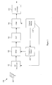
Figure 1 is a diagram illustrating a portion of an exemplarymultimode communication system 100, in accordance with various aspects of the present invention. Themultimode communication system 100 may comprise characteristics of any of a variety of communication systems. For example and without limitation, the multimode communication system may comprise characteristics of any of a variety of mobile communication devices (e.g., cellular phones, paging devices, portable email devices, personal digital assistance, etc.). Also for example, thecommunication system 100 may comprise characteristics of fixed communication systems or devices (e.g., network access points, base stations, satellites, wireless routers, set top boxes, etc.). Further for example, thecommunication system 100 may comprise characteristics of a variety of electronic devices with wireless communication capability (e.g., televisions, music players, cameras, remote controls, etc.) Accordingly, the scope of various aspects of the present invention should not be limited by characteristics of particular communication systems or devices. - The following discussion will refer to various communication modes. For the following discussion, a communication mode may generally be considered to coincide with communication utilizing a particular communication protocol or standard. A non-limiting list of exemplary communication protocols includes various cellular communication protocols (e.g., GSM, GRPS, EDGE, CDMA, WCDMA, TDMA, PDC, etc.), various wireless networking protocols or standards, including WLAN, WMAN, WPAN and WWAN (e.g., IEEE 802.11, Bluetooth, IEEE 802.15, UWB, IEEE 802.16, IEEE 802.20, any WiFi protocol, etc.), various television communication standards, etc. Accordingly, the scope of various aspects of the present invention should not be limited by characteristics of particular communication protocols, either standard or proprietary.
- The
exemplary communication system 100 may comprise anRF antenna 105. As illustrated inFigure 1 , thesystem 100 may, in various exemplary configurations, comprise a plurality of RF antennas (e.g., in a MIMO configuration, MISO configuration, beam-forming configuration, configuration where particular communication modes utilize particular antennas, etc.). Though the following discussion will generally discuss RF signals received through one antenna and processed through one signal-processing pathway, it should be understood that various aspects of the present invention are readily extensible to system configurations utilizing a plurality of antennas and/or signal processing pathways. - The
exemplary system 100 comprises at least oneRF signal receiver 110 adapted to receive RF signals corresponding to a plurality of communication protocols. In a non-limiting exemplary scenario, theRF signal receiver 110 may be adapted to receive a first RF signal corresponding to a first communication protocol and a second RF signal corresponding to a second communication protocol. - The
RF signal receiver 110 may comprise characteristics of any of a variety of RF receiving circuitry. Such circuitry may, for example, comprise filter circuitry, low-noise amplifier ("LNA") circuitry, noise cancellation circuitry, etc. - The
exemplary system 100 may comprise amixer 120. Themixer 120 may, for example, be adapted to convert a received RF signal to an IF signal through mixing a received RF signal with a mixing signal having a particular intermediate mixing frequency. Themixer 120 may also, for example, be adapted to convert a received RF signal to a signal at baseband frequency through mixing a received RF signal with a mixing signal having the frequency of the received RF signal. - In a non-limiting exemplary scenario, the
mixer 120 may be adapted to receive a first RF signal (e.g., from the RF receiver 110) and a first mixing signal characterized by a first intermediate frequency, mix the first RF signal and first mixing signal, and output a first IF signal characterized by a first intermediate frequency. Continuing, themixer 120 may also be adapted to receive a second RF signal (e.g., from the RF receiver 110) and a second mixing signal characterized by a second intermediate frequency, mix the second RF signal and the second mixing signal, and output a second IF signal characterized by the second intermediate frequency. For example, the first and second RF/mixing signal pairs may be received serially. Continuing the non-limiting exemplary scenario, themixer 120 may also be adapted to receive a third RF signal (e.g., from the RF receiver 110) and a third mixing signal characterized by a third mixing frequency (e.g., characterized by the frequency of the third RF signal), mix the third RF signal and the third mixing signal, and output a third signal characterized by a baseband frequency. - The
system 100 may also comprise afrequency source 160 that is adapted to output a mixing signal (e.g., to the mixer 120). Thefrequency source 160 may, for example, be adapted to output a mixing signal characterized by one of a plurality of selectable frequencies (e.g., IF frequencies, RF frequencies and in various scenarios, a frequency of zero). For example, thefrequency source 160 may be adapted to receive a frequency control signal, determine the frequency of the mixing signal based at least in part on the received frequency control signal, and output the mixing signal characterized by the determined frequency. - The
frequency source 160 may comprise characteristics of any of a variety of frequency generating/synthesizing circuits. For example, thefrequency source 160 may comprise characteristics of a local oscillator. Also for example, thefrequency source 160 may comprise characteristics of a fractional-N synthesizer. Thefrequency source 160 may comprise characteristics of any of a variety of circuits adapted to output a signal at a controllable, programmable or otherwise selectable frequency. - In a non-limiting exemplary scenario, in response to a first frequency control signal, the
frequency source 160 may be adapted to generate (or output) a mixing signal characterized by a first intermediate mixing frequency corresponding to a first communication protocol. Continuing, in response to a second frequency control signal, thefrequency source 160 may be adapted to generate a mixing signal characterized by a second intermediate mixing frequency corresponding to a second communication protocol. Further, in response to a third frequency control signal, thefrequency source 160 may be adapted to generate a mixing signal characterized by an RF frequency corresponding to a third communication protocol (e.g., for direct conversion from RF to baseband). - In another non-limiting exemplary scenario, in response to a first frequency control signal, the
frequency source 160 may be adapted to generate (or output) a mixing signal characterized by a first intermediate frequency corresponding to the GSM communication protocol. Such an intermediate frequency may, for example, be approximately 100 KHz or, for example, less than or equal to 150 KHz. Then in response to a second frequency control signal, thefrequency source 160 may be adapted to generate (or output) a mixing signal characterized by a second intermediate frequency corresponding to the EDGE communication protocol. Such an intermediate frequency may, for example, be approximately 300 KHz, 200 KHz or, for example, greater than or equal to 150 KHz. Then in response to a third frequency control signal, thefrequency source 160 may be adapted to generate (or output) a mixing signal characterized by an RF frequency corresponding to the WCDMA protocol. Such a mixing signal may, for example, be utilized by a mixer (e.g., themixer 120 or other mixer) for direct conversion of the WCDMA signal from RF to baseband. - The
exemplary system 100 may also comprise a variety of amplifier and/or gain control circuitry. For example, theexemplary system 100 is illustrated with anAGC module 130 adapted to control the amplitude of a signal processed by theAGC module 130. TheAGC module 130 may, for example, be adapted to maintain amplitude of a signal corresponding to any of a variety of communication protocols. Such a signal may, for example, be at an intermediate frequency or a baseband frequency. - The
exemplary system 100 may also comprise any of a variety of additional signal handling/processing circuitry that is not illustrated inFigure 1 . Various circuitry, which may be typical in various communication scenarios, has been excluded fromFigure 1 for illustrative clarity. - The
exemplary system 100 may further comprise a filter 140 (e.g., communicatively coupled to the mixer 120). Thefilter 140 may, for example, be adapted to filter a signal in accordance with a plurality of selectable sets of filter characteristics. Non-limiting characteristics of exemplary controllable filters are presented in U.S. patent application no. _/_,_, entitled "MULTIMODE COMMUNICATION DEVICE WITH SHARED SIGNAL PATH PROGRAMMABLE FILTER," with attorney docket number 16887US02, which is hereby incorporated herein in its entirety by reference. - A set of filter characteristics may, for example, correspond to a particular communication mode (or protocol). For example and without limitation, a first set of filter characteristics may correspond to a first communication protocol and comprise a first filter bandwidth and/or first filter center frequency. A second set of filter characteristics may then, for example, correspond to a second communication protocol and comprise a second filter bandwidth and/or second filter center frequency. An Nth set of filter characteristics may, for example, correspond to an Nth communication protocol and comprise an Nth filter bandwidth and/or Nth filter center frequency.
- In a non-limiting exemplary scenario, a first set of filter characteristics may correspond to the GSM protocol and comprise a relatively narrow filter bandwidth, and a second set of filter characteristics may correspond to the WCDMA protocol and comprise a relatively wide filter bandwidth.
- Though the
exemplary filter 140 illustrated inFigure 1 is an analog filter, various aspects of the present invention are readily extensible to digital filters or analog/digital hybrid filters. Additionally, though only one filter with selectable filter characteristics is illustrated inFigure 1 , more than one of such filters may be utilized. As a non-limiting example, thefirst filter 140 may be as described above, and a second filter (e.g., a digital filter) may be communicatively coupled to the output of the A/D converter 150. - The
exemplary system 100 may also include acontrol module 170 that is adapted to direct thefrequency source 160 to generate the mixing signal at a particular frequency. For example, thecontrol module 170 may communicate a frequency control signal to thefrequency source 160. Such a control signal may be a continuous signal utilized to continuously control thefrequency source 160, an intermittent signal, a triggering signal, or may be a programming signal that programs thefrequency source 160 to generate a mixing signal at a particular frequency. - The
control module 170 may also, for example, be adapted to direct a filter (e.g., thefilter 140 and/or other filters) to filter a signal in accordance with a particular set of filter characteristics. Thecontrol module 170 may further, for example, be adapted to direct an RF receiver (e.g., the RF receiver 110) to receive a particular RF signal. - In a non-limiting exemplary scenario, the control module 170 (or other module communicatively coupled to the control module 170) may determine to receive a signal corresponding to a first communication protocol. The
control module 170 may then, for example, direct any or all of theRF receiver 110, thefrequency source 160 and thefilter 140 to operate in accordance with the first communication protocol. For example, thecontrol module 170 may communicate a control signal to theRF receiver 110 to receive an RF signal corresponding to the first communication protocol, communicate a control signal to thefrequency source 160 to generate a mixing signal characterized by an intermediate frequency corresponding to the first communication protocol, and communicate a control signal to thefilter 140 to filter a signal according to a first set of filter characteristics corresponding to the first communication protocol. - Continuing the non-limiting exemplary scenario, the control module 170 (or other module communicatively coupled to the control module 170) may determine to receive a signal corresponding to a second communication protocol. The
control module 170 may then, for example, direct any or all of theRF receiver 110, thefrequency source 160 and thefilter 140 to operate in accordance with the second communication protocol. For example, thecontrol module 170 may communicate a control signal to theRF receiver 110 to receive an RF signal corresponding to the second communication protocol, communicate a control signal to thefrequency source 160 to generate a mixing signal characterized by an intermediate frequency corresponding to the second communication protocol, and communicate a control signal to thefilter 140 to filter a signal according to a second set of filter characteristics corresponding to the second communication protocol. - In another non-limiting exemplary scenario, the
exemplary communication system 100 may receive time-multiplexed information corresponding to a plurality of communication protocols. For example, theRF signal receiver 110 may be adapted to receive a first RF signal and a second RF signal in a time-multiplexed manner. In such a scenario, during time windows corresponding to the first communication protocol, thecontrol module 170 may be adapted to direct theRF signal receiver 110 to receive the first RF signal, direct thefrequency source 160 to output a mixing signal at a first mixing frequency corresponding to the first communication protocol, and direct thefilter 140 to filter in accordance with a first set of filter characteristics corresponding to the first communication protocol. During time windows corresponding to the second communication protocol, thecontrol module 170 may be adapted to direct theRF signal receiver 110 to receive the second RF signal, direct thefrequency source 160 to output a mixing signal at a second mixing frequency corresponding to the second communication protocol, and direct thefilter 140 to filter in accordance with a second set of filter characteristics corresponding to the second communication protocol. - The
exemplary system 100 was presented to provide non-limiting illustrations of a portion of various aspects of the present invention. Accordingly, the scope of various aspects of the present invention should not be limited by particular characteristics of theexemplary system 100. -
Figure 2 is a diagram illustrating a portion of an exemplarymultimode communication system 200, in accordance with various aspects of the present invention. Theexemplary system 200 may, for example and without limitation, share any or all characteristics with theexemplary system 100 illustrated inFigure 1 and discussed previously. - The
exemplary communication system 200 may comprise anRF antenna 205. Theexemplary system 200 may also comprise at least oneRF signal receiver 210 adapted to receive RF signals corresponding to a plurality of communication protocols. TheRF antenna 205 andRF signal receiver 210 may, for example and without limitation, share any or all characteristics with theantenna 105 and RF signal receiver(s) 110 of thesystem 100 illustrated inFigure 1 and discussed previously. TheRF signal receiver 210 may, for example, comprise an RF filter 212 (e.g., band-pass, low-pass and/or high-pass) and a low-noise amplifier 214, among other circuitry. - In a non-limiting exemplary scenario, the
RF signal receiver 210 may be adapted to receive a first RF signal corresponding to a first communication protocol and a second RF signal corresponding to a second communication protocol. - The
exemplary system 200 also comprises amixer 220 and afrequency source 260 that may, for example and without limitation, share any or all characteristics with themixer 120 andfrequency source 160 of theexemplary system 100 illustrated inFigure 1 and discussed previously. - The
frequency source 260 may, for example, be adapted to output a mixing signal characterized by one of a plurality of selectable frequencies (e.g., IF and/or RF frequencies). For example, thefrequency source 260 may be adapted to receive a frequency control signal, determine the frequency of a mixing signal based at least in part on the received frequency control signal, and output the mixing signal characterized by the determined frequency. - Though the
frequency source 260 is illustrated including a fractional-N synthesizer 262, thefrequency source 260 may comprise characteristics of any of a variety of frequency generating/synthesizing circuits (e.g., circuits adapted to output a signal at a controllable, programmable or otherwise selectable frequency). - In a non-limiting exemplary scenario, in response to a first frequency control signal, the fractional-
N synthesizer 262 may be adapted to generate (or output) a mixing signal characterized by a first intermediate mixing frequency corresponding to a first communication protocol. Continuing, in response to a second frequency control signal, the fractional-N synthesizer 262 may be adapted to generate a mixing signal characterized by a second intermediate mixing frequency corresponding to a second communication protocol. Further, in response to a third frequency control signal, the fractional-N synthesizer 262 may be adapted to generate a mixing signal characterized by an RF frequency corresponding to a third communication protocol (e.g., for direct conversion from RF to baseband). - In another non-limiting exemplary scenario, in response to a first frequency control signal, the fractional-
N synthesizer 262 may be adapted to generate (or output) a mixing signal characterized by a first intermediate frequency corresponding to the GSM communication protocol. Such an intermediate frequency may, for example, be approximately 100 KHz or, for example, less than or equal to 150 KHz. Then in response to a second frequency control signal, the fractional-N synthesizer 262 may be adapted to generate (or output) a mixing signal characterized by a second intermediate frequency corresponding to the EDGE communication protocol. Such an intermediate frequency may, for example, be approximately 300 KHz, 200 KHz or, for example, greater than or equal to 150 KHz. Then in response to a third frequency control signal, the fractional-N synthesizer 262 may be adapted to generate (or output) a mixing signal characterized by an RF frequency corresponding to the WCDMA protocol. Such a mixing signal may, for example, be utilized by a mixer (e.g., themixer 220 or other mixer) for direct conversion of the WCDMA signal from RF to baseband. - The
exemplary system 200 may also comprise a variety of amplifier and/or gain circuitry (e.g., an AGC module 230). TheAGC module 230 may, for example, be adapted to maintain amplitude of a signal corresponding to any of a variety of communication protocols. Such a signal may, for example, be at an intermediate frequency or a baseband frequency. - The
exemplary system 200 may further comprise a filter 240 (e.g., communicatively coupled to the mixer). The filter may, for example and without limitation, share any or all characteristics with theexemplary filter 240 illustrated inFigure 1 and discussed previously. Thefilter 240 may, for example, be adapted to filter a signal in accordance with a plurality of selectable sets of filter characteristics. Such sets of filter characteristics may, for example, include bandwidth characteristics, center frequency characteristics, fall-off characteristics, analog/digital filter characteristics, tap number, IIR vs. FIR configuration, etc. As discussed previously, a set of filter characteristics may, for example, correspond to a particular communication mode (or protocol). Also as discussed previously, though theexemplary filter 240 illustrated inFigure 2 is an analog filter, various aspects of the present invention are readily extensible to digital filters or analog/digital hybrid filters. Additionally, through only one filter with selectable filter characteristics is illustrated inFigure 2 , more than one of such filters may be utilized. As a non-limiting example, afirst filter 240 may be as described above, and a second filter (e.g., a digital filter) may be communicatively coupled to the output of the A/D converter 250. - The
exemplary system 200 may also include acontrol module 270 that is adapted to direct the frequency source 260 (e.g., the fractional-N synthesizer 262) to generate the mixing signal at a particular frequency, direct thefilter 240 to filter a signal in accordance with a particular set of filter characteristics and/or direct theRF receiver 210 to receive a particular RF signal. Thecontrol module 270 may, for example and without limitation, share any or all characteristics with thecontrol module 170 illustrated inFigure 1 . - The
exemplary system 200 was presented to provide non-limiting illustrations of a portion of various aspects of the present invention. Accordingly, the scope of various aspects of the present invention should not be limited by particular characteristics of theexemplary system 200. -
Figure 3 is a diagram illustrating amethod 300 for operating a multimode communication system, in accordance with various aspects of the present invention. Theexemplary method 300 may, for example and without limitation, share various functional characteristics with theexemplary systems Figures 1-2 and discussed previously. - As discussed previously, a multimode communication system implementing the method 300 (or other methods discussed herein) may comprise characteristics of any of a variety of communication systems. For example and without limitation, the multimode communication system may comprise characteristics of mobile communication devices (e.g., cellular phones, paging devices, portable email devices, personal digital assistance, etc.). Also for example, the communication system may comprise characteristics of fixed communication systems or devices (e.g., network access points, base stations, satellites, wireless routers, set top boxes, etc.). Further for example, the communication system may comprise characteristics of a variety of electronic devices with wireless communication capability (e.g., televisions, music players, cameras, remote controls, etc.) Accordingly, the scope of various aspects of the present invention should not be limited by characteristics of particular communication systems or devices.
- The
exemplary method 300 may begin executing atstep 305. Theexemplary method 300 may begin executing for any of a variety of reasons. For example, theexemplary method 300 may begin executing upon the arrival of (or detection of) an RF signal. Also for example, theexemplary method 300 may begin in response to waking from a sleep mode or in response to a user or system command. Accordingly, the scope of various aspects of the present invention should not be limited by characteristics if any particular initiating causes or conditions. - The
exemplary method 300 may, atstep 310, comprise receiving a first RF signal corresponding to a first communication mode (or protocol). Step 310 may, for example and without limitation, share any or all functional characteristics with theRF receivers Figures 1-2 and discussed previously. - Step 310 may comprise receiving the first RF signal in any of a variety of manners. For example, step 310 may comprise receiving the first RF signal utilizing one or a plurality of RF antennas (e.g., in a MIMO configuration, MISO configuration, beam-forming configuration, etc.). Also, for example, step 310 may comprise receiving the first RF signal utilizing filtering and/or amplifier circuitry adapted to receive/process RF signals corresponding to any of a plurality of communication protocols.
- Step 310 may, for example, comprise receiving the first RF signal utilizing an RF signal receiver that is adapted to receive RF signals corresponding to a plurality of respective communication protocols. Such an RF signal receiver may, for example, be adapted to receive a first RF signal corresponding to a first communication protocol and a second RF signal corresponding to a second communication protocol.
- The
exemplary method 300 may, atstep 320, comprise directing a frequency source to generate a first mixing signal characterized by a first frequency corresponding to the first communication protocol. Step 320 may, for example and without limitation, share various functional characteristics with thefrequency sources control modules Figures 1-2 and discussed previously. - The frequency source may comprise any of a variety of characteristics. For example, the frequency source may be adapted to output a mixing signal characterized by one of a plurality of selectable frequencies (e.g., IF and/or RF frequencies). For example, the frequency source may be adapted to receive a frequency control signal, determine the frequency of a mixing signal based at least in part on the received frequency control signal, and output the mixing signal characterized by the determined frequency. In such an exemplary configuration,
step 320 may comprise generating a control signal provided to such a frequency source directing the frequency source to generate a mixing signal characterized by the first frequency. - In a non-limiting exemplary scenario, step 320 may comprise generating a frequency control signal and providing such a control signal to a fractional-N synthesizer to generate the first mixing signal. Alternatively for example, step 320 may comprise directing a local oscillator or other frequency synthesizer to generate the first mixing signal.
- Depending on the configuration of the frequency source, step 320 may, for example, comprise directing the frequency source by providing a continuous control signal, an intermittent control signal, a triggering control signal, or by communicating data utilized to program the frequency source.
- In a non-limiting exemplary scenario, in response to a first frequency control signal generated at
step 320, the frequency source may generate (or output) a mixing signal characterized by a first intermediate mixing frequency corresponding to a first communication protocol. - In another non-limiting exemplary scenario, in response to a first frequency control signal generated at
step 320, the frequency source may generate (or output) a mixing signal characterized by a first intermediate frequency corresponding to the GSM communication protocol. Such an intermediate frequency may, for example, be approximately 100 KHz or, for example, less than or equal to 150 KHz. In yet another non-limiting exemplary scenario, in response to a first frequency control signal generated atstep 320, the frequency source may generate a mixing signal characterized by a second intermediate frequency corresponding to the EDGE communication protocol. Such an intermediate frequency may, for example, be approximately 300 KHz, 200 KHz or, for example, greater than or equal to 150 KHz. In still another non-limiting exemplary scenario, in response to a first frequency control signal generated atstep 320, the frequency source may generate a mixing signal characterized by an RF frequency corresponding to the WCDMA protocol. Such a mixing signal may, for example, be utilized by a mixer (e.g., at step 330) for direct conversion of the WCDMA signal from RF to baseband. - The
exemplary method 300 may, atstep 330, comprise mixing the first RF signal (e.g., received at step 310) with the first mixing signal (e.g., from the frequency source directed at step 320) at a mixer. Step 330 may, for example and without limitation, share various functional characteristics with themixers Figures 1-2 and discussed previously. - For example, step 330 may comprise utilizing a mixer (or similar device) to convert the first received RF signal (e.g., received at step 310) to an IF signal through mixing the first received RF signal with a mixing signal having a particular intermediate mixing frequency (e.g., as directed at step 320). Step 330 may also, for example, comprise utilizing the mixer to convert the first received RF signal to a signal at baseband frequency through mixing the first received RF signal with a mixing signal having the frequency of the received RF signal (e.g., as directed at step 320).
- The
exemplary method 300 may, atstep 340, comprise receiving a second RF signal corresponding to a second communication mode (or protocol). Step 340 may, for example and without limitation, share any or all characteristics withstep 310 discussed previously. - For example, step 340 may comprise receiving the second RF signal in any of a variety of manners. For example, step 340 may comprise receiving the second RF signal utilizing one or a plurality of RF antennas (e.g., in a MIMO configuration, MISO configuration, beam-forming configuration, etc.). Such one or more RF antennas may, for example, be the same as antenna(s) utilized at
step 310 or may be different. Also, step 340 may comprise receiving the second RF signal utilizing filtering and/or amplifier circuitry adapted to receive/process RF signals corresponding to any of a plurality of communication protocols. Such circuitry may, for example, be the same as that utilized atstep 310 or may be different. - Step 340 may comprise receiving the second RF signal utilizing an RF signal receiver that is adapted to receive RF signals corresponding to a plurality of respective communication protocols. Such an RF signal receiver may, for example, be adapted to receive a first RF signal corresponding to a first communication protocol and a second RF signal corresponding to a second communication protocol. Such an RF signal receiver may, for example, be the same as that utilized at
step 310 or may be different. - In a non-limiting exemplary scenario where
steps steps - The
exemplary method 300 may, atstep 350, comprise directing the frequency source (e.g., the same frequency source directed atstep 320 or the same type of frequency source) to generate a second mixing signal characterized by a second frequency corresponding to a second communication protocol. Step 350 may, for example and without limitation, share any or all characteristics withstep 320 discussed previously. - The frequency source may be the same frequency source as that directed at
step 320 or may share any or all characteristics with the frequency source directed atstep 320. For example, the frequency source may be adapted to output a mixing signal characterized by one of a plurality of selectable frequencies (e.g., IF and/or RF frequencies). For example, the frequency source may be adapted to receive a frequency control signal, determine the frequency of a mixing signal based at least in part on the received frequency control signal, and output the mixing signal characterized by the determined frequency. In such an exemplary configuration,step 350 may comprise generating a control signal provided to such a frequency source directing the frequency source to generate a mixing signal characterized by the second frequency. - In a non-limiting exemplary scenario, step 350 may comprise generating a frequency control signal and providing such a control signal to a fractional-N synthesizer to generate the second mixing signal. Alternatively for example, step 350 may comprise directing a local oscillator or other frequency synthesizer to generate the second mixing signal.
- Depending on the configuration of the frequency source, step 350 may, for example, comprise directing the frequency source by providing a continuous control signal, an intermittent control signal, a triggering control signal, or by communicating data utilized to program the frequency source.
- In a non-limiting exemplary scenario, in response to a first frequency control signal generated at
step 350, the frequency source may generate (or output) a mixing signal characterized by a second intermediate mixing frequency corresponding to a second communication protocol. - In another non-limiting exemplary scenario, in response to a second frequency control signal generated at
step 350, the frequency source may generate (or output) a mixing signal characterized by a second intermediate frequency corresponding to the GSM communication protocol. Such an intermediate frequency may, for example, be approximately 100 KHz or, for example, less than or equal to 150 KHz. In yet another non-limiting exemplary scenario, in response to a second frequency control signal generated atstep 350, the frequency source may generate a mixing signal characterized by a second intermediate frequency corresponding to the EDGE communication protocol. Such an intermediate frequency may, for example, be approximately 300 KHz, 200 KHz or, for example, greater than or equal to 150 KHz. In still another non-limiting exemplary scenario, in response to a second frequency control signal generated atstep 350, the frequency source may generate a mixing signal characterized by an RF frequency corresponding to the WCDMA protocol. Such a mixing signal may, for example, be utilized by a mixer (e.g., at step 360) for direct conversion of the WCDMA signal from RF to baseband. - The
exemplary method 300 may, atstep 360, comprise mixing the second RF signal and the second mixing signal at the mixer (e.g., the same mixer utilized at step 330). Step 360 may, for example and without limitation, share any or all characteristics withstep 330 discussed previously. - For example, step 360 may comprise utilizing the mixer to convert the second received RF signal (e.g., received at step 340) to an IF signal through mixing the second received RF signal with a mixing signal having a particular intermediate mixing frequency (e.g., as directed at step 350). Step 360 may also, for example, comprise utilizing the mixer to convert the second received RF signal to a signal at baseband frequency through mixing the second received RF signal with a mixing signal having the frequency of the received RF signal (e.g., as directed at step 350).
- The
exemplary method 300 may, atstep 395, perform any of a large variety of continued processing. For example and without limitation, step 395 may comprise processing various signals utilizing automatic gain control. Step 395 may also, for example, comprise converting signals between the analog and digital domains. Further for example, step 395 may comprise performing additional filtering of various signals. - In a non-limiting exemplary scenario, the first and second RF signals may be received and processed in a time-multiplexed manner. In such a scenario, steps 310-330 might be executed during reception of RF signals corresponding to a first communication protocol, and steps 340-360 might be executed during reception of RF signals corresponding to a second communication protocol. In such a scenario, step 395 may comprise directing execution flow of the
exemplary method 300 according to the type of RF signal that is presently being received. -
Figure 4 is a diagram illustrating amethod 400 for operating a multimode communication system, in accordance with various aspects of the present invention. Theexemplary method 400 may, for example and without limitation, share any or all characteristics with themethod 300 illustrated inFigure 3 and discussed previously. - The
exemplary method 400 may, at steps 410-430, comprise receiving a first RF signal corresponding to a first communication protocol (or mode), directing a frequency source to generate a first mixing signal characterized by a first frequency corresponding to the first communication protocol, and mixing the first RF signal and the first mixing signal at a mixer (or similar module). Steps 410-430 may, for example and without limitation, share any or all characteristics with steps 310-330 of theexemplary method 300 illustrated inFigure 3 and discussed previously. - The
exemplary method 400 may, atstep 432, comprise filtering a mixed signal in accordance with a selected one of a plurality of selectable sets of filter characteristics. Step 432 may, for example, comprise directing a filter (e.g., a controllable filter) to filter the mixed signal in accordance with the selected set of filter characteristics. Step 432 may, for example and without limitation, share any or all functional characteristics with thecontrol modules filters Figures 1-2 and discussed previously. - Various exemplary characteristics of controllable filters and selectable sets of filter characteristics were presented previously. For example, step 432 may comprise performing various filtering or filter control operations, such as, for example, those presented in U.S. patent application no. _/_,_, entitled "MULTIMODE COMMUNICATION DEVICE WITH SHARED SIGNAL PATH PROGRAMMABLE FILTER," with attorney docket number 16887US02, which is hereby incorporated herein in its entirety by reference.
- Also for example, a set of filter characteristics may correspond to a particular communication protocol (or mode). For example and without limitation, a first set of filter characteristics may correspond to a first communication protocol and comprise a first filter bandwidth and/or first filter center frequency. A second set of filter characteristics may then, for example, correspond to a second communication protocol and comprise a second filter bandwidth and/or second filter center frequency. An Nth set of filter characteristics may, for example, correspond to an Nth communication protocol and comprise an Nth filter bandwidth and/or Nth filter center frequency.
- In a non-limiting exemplary scenario, a first set of filter characteristics may correspond to the GSM protocol and comprise a relatively narrow filter bandwidth, and a second set of filter characteristics may correspond to the WCDMA protocol and comprise a relatively wide filter bandwidth.
- Note that
step 432 may comprise directing and/or performing analog and/or digital filtering. Also note thatstep 432 may comprise directing one or more of a plurality of filters to perform desired filtering functionality. Such analog/digital filtering may accordingly be combined with any desired conversion between the analog and digital domains. - In a non-limiting exemplary scenario, a communication system implementing the exemplary method 400 (or module of such a system) may determine to receive a signal corresponding to a first communication protocol. Step 410 may then comprise receiving the first RF signal corresponding to the first communication protocol,
step 420 may comprise directing the frequency source to generate a first mixing signal characterized by a frequency corresponding to the first communication protocol,step 430 may comprise mixing the received first RF signal and the first mixing signal to produce a first mixed signal, and step 432 may comprise directing a filter to filter the first mixed signal (or signal representative thereof) in accordance with a selected first set of filter characteristics corresponding to the first communication protocol. - The
exemplary method 400 may, atstep 434, comprise performing various types of additional processing with a communication signal (e.g., as received atstep 420, mixed at steps 420-430 and filtered at step 432). For example and without limitation, such further processing may comprise performing various amplification (e.g., AGC control), analog/digital conversion, filtering, digital signal processing, and other operations. - The
exemplary method 400 may, at steps 440-460, comprise receiving a second RF signal corresponding to a second communication mode, directing a frequency source to generate a second mixing signal characterized by a second frequency corresponding to the second communication protocol, and mixing the second RF signal and the second mixing signal at a mixer (or similar module). Steps 440-460 may, for example and without limitation, share any or all characteristics with steps 340-360 of theexemplary method 300 illustrated inFigure 3 and discussed previously. - The
exemplary method 400 may, atstep 462, comprise filtering a mixed signal in accordance with a selected one of a plurality of selectable sets of filter characteristics. Step 462 may, for example, comprise directing a filter (e.g., a controllable filter) to filter the mixed signal in accordance with the selected set of filter characteristics. Step 462 may, for example and without limitation, share any or all functional characteristics withstep 432 discussed previously. Various non-limiting exemplary aspects of filters and sets of filter characteristics were discussed previously. - In a non-limiting exemplary scenario, after receiving and processing a communication signal corresponding to a first communication protocol at steps 410-434, a communication system implementing the exemplary method 400 (or module of such a system) may determine to receive and process a signal corresponding to a second communication protocol. Step 440 may then, for example, comprise receiving the second RF signal corresponding to the second communication protocol,
step 450 may comprise directing the frequency source to generate a second mixing signal characterized by a frequency corresponding to the second communication protocol,step 460 may comprise mixing the received second RF signal and the second mixing signal to produce a second mixed signal, and step 462 may comprise directing a filter to filter the second mixed signal (or signal representative thereof) in accordance with a selected second set of filter characteristics corresponding to the second communication protocol. - The
exemplary method 400 may, atstep 464, comprise performing various types of additional processing with a communication signal (e.g., as received atstep 440, mixed at steps 450-460 and filtered at step 462). For example and without limitation, such further processing may comprise performing various amplification (e.g., AGC control), analog/digital conversion, filtering, digital signal processing, and other operations. - The
exemplary method 400 may, atstep 495, comprise performing any of a large variety of continued processing, various examples of which were provided previously in the discussion ofstep 395 ofFigure 3 . - In a non-limiting exemplary scenario, the first and second RF signals may be received and processed in a time-multiplexed manner. In such a scenario, steps 410-434 might be executed during reception of RF signals corresponding to a first communication protocol, and steps 440-464 might be executed during reception of RF signals corresponding to a second communication protocol. In such a scenario, step 495 may comprise directing execution flow of the
exemplary method 400 according to the type of RF signal that is presently being received. - The
exemplary methods exemplary methods - For illustrative clarity, the exemplary systems 100-200 were presented in terms of various functional modules. Various modules may, for example, be implemented in hardware, software or a combination thereof. Various module may, for example, be implemented in a single integrated circuit or combination of integrated circuits. Also, various modules may share various sub-modules and/or subcomponents. For example and without limitation, various hardware modules may share various electrical components, and various software modules may share various software subroutines. Accordingly, the scope of various aspects of the present invention should not be limited by characteristics of any particular hardware and/or software implementation or by any arbitrary boundaries between various functional modules.
- In summary, various aspects of the present invention provide a system and method providing variable-frequency IF conversion in a multimode communication device. While the invention has been described with reference to certain aspects and embodiments, it will be understood by those skilled in the art that various changes may be made and equivalents may be substituted without departing from the scope of the invention. In addition, many modifications may be made to adapt a particular situation or material to the teachings of the invention without departing from its scope. Therefore, it is intended that the invention not be limited to the particular embodiment disclosed, but that the invention will include all embodiments falling within the scope of the appended claims.
Advantageously, the frequency source is programmable.
Advantageously, the first communication protocol is GSM and the second communication protocol is EDGE.
Advantageously, the first mixing frequency is an intermediate frequency less than 150 KHz, and the second mixing frequency is an intermediate frequency greater than 150 KHz.
Advantageously, the first communication protocol is WCDMA.
Advantageously, the first mixing frequency is an RF frequency utilized by the mixer for direct conversion of the first RF signal to a baseband frequency.
Advantageously, the multimode communication device further comprises a filter, communicatively coupled to the mixer, adapted to filter a signal in accordance with a selected one of a plurality of selectable sets of filter characteristics.
Advantageously, the plurality of selectable sets of filter characteristics comprises:
Advantageously, the at least module is communicatively coupled to the filter and adapted to direct the filter to filter a received signal at a selected one of the plurality of selectable sets of filter characteristics.
Advantageously, the multimode communication device further comprises an AGC module, communicatively coupled to the mixer and the filter, adapted to amplify a received signal corresponding to a plurality of communication protocols comprising the first communication protocol and the second communication protocol.
Advantageously:
According to an aspect of the invention, in a multimode communication device, a method for receiving a plurality of RF signals corresponding to a plurality of respective communication protocols is provided, the method comprising:
Advantageously:
Advantageously, the first mixing frequency is an intermediate frequency less than 150 KHz, and the second mixing frequency is an intermediate frequency greater than 150 KHz.
Advantageously, the first communication protocol is WCDMA.
Advantageously, the first mixing frequency is an RF frequency utilized by the mixer for direct conversion of an RF signal to a baseband frequency.
Advantageously, the method further comprises filtering a mixed signal in accordance with a selected one of a plurality of selectable sets of filter characteristics.
Advantageously, the plurality of selectable sets of filter characteristics comprises:
Advantageously, the method further comprises performing automatic gain control on the mixed signal prior to filtering the mixed signal.
Advantageously:
According to an aspect of the invention, a multimode communication device comprises:
Claims (15)
- A multimode communication device comprising:at least one RF signal receiver adapted to receive a first RF signal corresponding to a first communication protocol and a second RF signal corresponding to a second communication protocol;a frequency source adapted to:receive at least one frequency control signal; andin response to the at least one frequency control signal, output a mixing signal at one of a plurality of selectable frequencies,a mixer, communicatively coupled to the at least one RF signal receiver and the frequency source; andat least one module, communicatively coupled to the frequency source, adapted to direct the frequency source to output the mixing signal at a selected one of the plurality of selectable frequencies; anda filter, communicatively coupled to the mixer, adapted to filter a signal in accordance with a selected one of a plurality of selectable sets of filter characteristics.
- The device of claim 1, the plurality of selectable sets of filter characteristics comprises:a first set of filter characteristics corresponding to the first communication protocol and comprising a first bandwidth; anda second set of filter characteristics corresponding to the second communication protocol and comprising a second bandwidth.
- The device of any preceding claim, the plurality of selectable sets of filter characteristics comprises:a first set of filter characteristics corresponding to the first communication protocol and comprising a first center frequency; anda second set of filter characteristics corresponding to the second communication protocol and comprising a second center frequency.
- The device of any preceding claim, wherein the filter is programmable.
- The device of any preceding claim, wherein the at least one module is communicatively coupled to the filter and adapted to direct the filter to filter a received signal at a selected one of the plurality of selectable sets of filter characteristics.
- The device of any preceding claim, further comprising an AGC module, communicatively coupled to the mixer and the filter, adapted to amplify a received signal corresponding to a plurality of communication protocols comprising the first communication protocol and the second communication protocol.
- The device of any preceding claim, wherein the frequency source comprises a fractional-N synthesizer.
- The device of any preceding claim, wherein the frequency source is programmable.
- The device of any preceding claim, wherein the first communication protocol is GSM and the second communication protocol is EDGE.
- The device of any preceding claim, wherein the plurality of selectable frequencies comprises a first mixing frequency corresponding to the first communication protocol and a second mixing frequency corresponding to the second communication protocol.
- The device of claim 10, wherein the first mixing frequency is an intermediate frequency less than 150 KHz, and the second mixing frequency is an intermediate frequency greater than 150 KHz.
- In a multimode communication device, a method for receiving a plurality of RF signals corresponding to a plurality of respective communication protocols, the method comprising:receiving a first RF signal corresponding to a first communication protocol;directing a frequency source to generate a first mixing signal characterized by a first frequency corresponding to the first communication protocol;mixing the first RF signal and the first mixing signal at a mixer;receiving a second RF signal corresponding to a second communication protocol;directing the frequency source to generate a second mixing signal characterized by a second frequency corresponding to the second communication protocol;mixing the second RF signal and the second mixing signal at the mixer; andfiltering a mixed signal in accordance with a selected one of a plurality of selectable sets of filter characteristics.
- The method of claim 12, wherein the plurality of selectable sets of filter characteristics comprises:a first set of filter characteristics corresponding to the first communication protocol and comprising a first bandwidth; anda second set of filter characteristics corresponding to the second communication protocol and comprising a second bandwidth.
- The method of claim 12 or 13, wherein the plurality of selectable sets of filter characteristics comprises:a first set of filter characteristics corresponding to the first communication protocol and comprising a first center frequency; anda second set of filter characteristics corresponding to the second communication protocol and comprising a second center frequency.
- The method of any of claims 12 to 14, wherein filtering a mixed signal in accordance with a selected one of a plurality of selectable sets of filter characteristics comprises programming a programmable filter to filter the mixed signal in accordance with the selected one of the plurality of selectable sets of filter characteristics.
Applications Claiming Priority (3)
| Application Number | Priority Date | Filing Date | Title |
|---|---|---|---|
| US73725805P | 2005-11-16 | 2005-11-16 | |
| US11/376,531 US7912428B2 (en) | 2005-11-16 | 2006-03-15 | System and method providing variable-frequency IF conversion in a multimode communication device |
| EP06016875A EP1788713A1 (en) | 2005-11-16 | 2006-08-11 | Multimode communication device using configurable front-end and related method |
Related Parent Applications (1)
| Application Number | Title | Priority Date | Filing Date |
|---|---|---|---|
| EP06016875.4 Division | 2006-08-11 |
Publications (1)
| Publication Number | Publication Date |
|---|---|
| EP2648340A1 true EP2648340A1 (en) | 2013-10-09 |
Family
ID=37807988
Family Applications (2)
| Application Number | Title | Priority Date | Filing Date |
|---|---|---|---|
| EP06016875A Ceased EP1788713A1 (en) | 2005-11-16 | 2006-08-11 | Multimode communication device using configurable front-end and related method |
| EP13003258.4A Ceased EP2648340A1 (en) | 2005-11-16 | 2006-08-11 | Multimode communication device using configurable front-end and related method |
Family Applications Before (1)
| Application Number | Title | Priority Date | Filing Date |
|---|---|---|---|
| EP06016875A Ceased EP1788713A1 (en) | 2005-11-16 | 2006-08-11 | Multimode communication device using configurable front-end and related method |
Country Status (3)
| Country | Link |
|---|---|
| US (2) | US7912428B2 (en) |
| EP (2) | EP1788713A1 (en) |
| TW (1) | TWI357237B (en) |
Families Citing this family (12)
| Publication number | Priority date | Publication date | Assignee | Title |
|---|---|---|---|---|
| US7912428B2 (en) * | 2005-11-16 | 2011-03-22 | Broadcom Corporation | System and method providing variable-frequency IF conversion in a multimode communication device |
| US7869781B2 (en) * | 2006-12-06 | 2011-01-11 | Broadcom Corporation | Method and system for mitigating the effects of pulling in multiple phase locked loops in multi-standard systems |
| US20090117938A1 (en) * | 2007-11-02 | 2009-05-07 | Broadcom Corporation | Ic for a high frequency communication device with minimal off chip components |
| CA2664502A1 (en) * | 2008-04-29 | 2009-10-29 | Hany Shenouda | Transceiver architecture |
| US20100046764A1 (en) * | 2008-08-21 | 2010-02-25 | Paul Wolff | Method and Apparatus for Detecting and Processing Audio Signal Energy Levels |
| US8340621B1 (en) * | 2008-11-19 | 2012-12-25 | Qualcomm Incorporated | Wireless device using a shared gain stage for simultaneous reception of multiple protocols |
| US8155612B1 (en) | 2008-11-19 | 2012-04-10 | Qualcomm Atheros, Inc. | Wireless device using a shared gain stage for simultaneous reception of multiple protocols |
| US8494469B2 (en) * | 2011-10-24 | 2013-07-23 | Spreadtrum Communications Usa Inc. | Detection and mitigation of interference in a multimode receiver using variable bandwidth filter |
| CN103248448A (en) * | 2013-04-02 | 2013-08-14 | 陕西天基通信科技有限责任公司 | TD-SCDMA/TD-LTE downlink shielding device and design method thereof |
| JP6146345B2 (en) * | 2014-03-04 | 2017-06-14 | ソニー株式会社 | Receiver, tuner and circuit |
| CN107005511B (en) | 2015-03-06 | 2020-01-10 | 华为技术有限公司 | System, method and device for processing wireless signal, wireless transformation module, router and user equipment |
| US11611360B2 (en) * | 2019-10-30 | 2023-03-21 | Silicon Laboratories Inc. | Apparatus for receiver with concurrent detection and associated methods |
Citations (4)
| Publication number | Priority date | Publication date | Assignee | Title |
|---|---|---|---|---|
| WO2000031885A1 (en) * | 1998-11-26 | 2000-06-02 | Nokia Mobile Phones Ltd. | Method and arrangement for transmitting and receiving rf signals through various radio interfaces of communication systems |
| US20020003844A1 (en) * | 1998-12-30 | 2002-01-10 | Markus Doetsch | Circuit configuration for a multistandard communications terminal |
| WO2003061174A2 (en) * | 2002-01-10 | 2003-07-24 | Berkana Wireless Inc. | Configurable wireless interface |
| US20050124377A1 (en) * | 2003-12-04 | 2005-06-09 | Did-Min Shih | Multi-mode and multi-band rf transceiver and related communications method |
Family Cites Families (30)
| Publication number | Priority date | Publication date | Assignee | Title |
|---|---|---|---|---|
| US3743941A (en) | 1971-10-28 | 1973-07-03 | Bell Telephone Labor Inc | Diversity receiver suitable for large scale integration |
| US5887020A (en) | 1991-05-13 | 1999-03-23 | Omnipoint Corporation | Multi-band, multi-mode spread-spectrum communication system |
| US5640694A (en) | 1995-05-03 | 1997-06-17 | Northrop Grumman Corporation | Integrated RF system with segmented frequency conversion |
| FR2742946B1 (en) * | 1995-12-22 | 1998-01-16 | Alcatel Mobile Comm France | MULTIMODE RADIOCOMMUNICATION TERMINAL |
| GB2310342A (en) | 1996-02-16 | 1997-08-20 | Northern Telecom Ltd | Dual mode radio transceiver front end |
| US6097974A (en) | 1997-12-12 | 2000-08-01 | Ericsson Inc. | Combined GPS and wide bandwidth radiotelephone terminals and methods |
| SE521035C2 (en) | 1997-12-29 | 2003-09-23 | Ericsson Telefon Ab L M | A receiver and a method for mobile radio, where the receiver is adapted for different radio communication networks, eg GSM, AMPS |
| US7430257B1 (en) | 1998-02-12 | 2008-09-30 | Lot 41 Acquisition Foundation, Llc | Multicarrier sub-layer for direct sequence channel and multiple-access coding |
| WO2000051907A1 (en) * | 1999-03-04 | 2000-09-08 | Kuraray Co. Ltd. | Fuel container |
| JP3818624B2 (en) | 2000-02-23 | 2006-09-06 | 株式会社ルネサステクノロジ | Wireless communication system |
| SE0003520L (en) * | 2000-09-29 | 2002-03-30 | Spirea Ab | More Standard Receiver |
| US6901243B2 (en) | 2001-11-08 | 2005-05-31 | Qualcomm, Incorporated | Method and apparatus for mitigating adjacent channel interference in a wireless communication system |
| US6917328B2 (en) | 2001-11-13 | 2005-07-12 | Rosum Corporation | Radio frequency device for receiving TV signals and GPS satellite signals and performing positioning |
| US7155231B2 (en) | 2002-02-08 | 2006-12-26 | Qualcomm, Incorporated | Transmit pre-correction in a wireless communication system |
| US7269424B2 (en) | 2002-10-16 | 2007-09-11 | Sony Ericsson Mobile Communications Ab | Mobile terminal implementing a ranging signal receiver and method |
| GB2394133A (en) | 2002-10-17 | 2004-04-14 | Toumaz Technology Ltd | Radio receiver with reconfigurable filtering arrangement |
| KR100542118B1 (en) | 2002-12-12 | 2006-01-11 | 한국전자통신연구원 | A digital intermediate-frequency signal processor and digital filter supporting software-defined radio system and its design |
| US7106816B2 (en) | 2002-12-18 | 2006-09-12 | Qualcomm Incorporated | Supporting multiple wireless protocols in a wireless device |
| US7283840B2 (en) | 2003-02-07 | 2007-10-16 | Chrontel, Inc. | Reconfigurable analog baseband for a single-chip dual-mode transceiver |
| WO2004095700A2 (en) | 2003-04-21 | 2004-11-04 | Quorum Systems, Inc. | Reconfigurable baseband filter |
| JP2005012648A (en) | 2003-06-20 | 2005-01-13 | Toshiba Corp | Radio communication apparatus and its transmitting/receiving circuit |
| US20050119025A1 (en) | 2003-12-02 | 2005-06-02 | Rishi Mohindra | Serial digital interface for wireless network radios and baseband integrated circuits |
| EP1723729A1 (en) * | 2004-03-10 | 2006-11-22 | Quorum Systems, Inc. | Transmitter and receiver architecture for multi-mode wireless device |
| US7463864B2 (en) | 2004-04-09 | 2008-12-09 | Broadcom Corporation | Modified dual band direct conversion architecture that allows extensive digital calibration |
| US7680477B2 (en) | 2004-09-03 | 2010-03-16 | Texas Instruments Incorporated | Integrated radio frequency filters for multiband transceivers |
| US7526052B2 (en) | 2004-12-21 | 2009-04-28 | Raytheon Company | Configurable filter and receiver incorporating same |
| US7558550B2 (en) * | 2005-02-17 | 2009-07-07 | Samsung Electronics Co., Ltd. | Versatile system for multimode, wireless communication receiver with ZIF and Near-ZIF operations |
| US7848463B2 (en) | 2005-04-07 | 2010-12-07 | Qualcomm Incorporated | Adaptive time-filtering for channel estimation in OFDM system |
| US7590396B2 (en) | 2005-10-06 | 2009-09-15 | Broadcom Corporation | Multimode communication device with shared signal path programmable filter |
| US7912428B2 (en) | 2005-11-16 | 2011-03-22 | Broadcom Corporation | System and method providing variable-frequency IF conversion in a multimode communication device |
-
2006
- 2006-03-15 US US11/376,531 patent/US7912428B2/en not_active Expired - Fee Related
- 2006-08-11 EP EP06016875A patent/EP1788713A1/en not_active Ceased
- 2006-08-11 EP EP13003258.4A patent/EP2648340A1/en not_active Ceased
- 2006-10-30 TW TW095139998A patent/TWI357237B/en active
-
2011
- 2011-03-21 US US13/052,572 patent/US8175544B2/en active Active
Patent Citations (4)
| Publication number | Priority date | Publication date | Assignee | Title |
|---|---|---|---|---|
| WO2000031885A1 (en) * | 1998-11-26 | 2000-06-02 | Nokia Mobile Phones Ltd. | Method and arrangement for transmitting and receiving rf signals through various radio interfaces of communication systems |
| US20020003844A1 (en) * | 1998-12-30 | 2002-01-10 | Markus Doetsch | Circuit configuration for a multistandard communications terminal |
| WO2003061174A2 (en) * | 2002-01-10 | 2003-07-24 | Berkana Wireless Inc. | Configurable wireless interface |
| US20050124377A1 (en) * | 2003-12-04 | 2005-06-09 | Did-Min Shih | Multi-mode and multi-band rf transceiver and related communications method |
Also Published As
| Publication number | Publication date |
|---|---|
| TW200733613A (en) | 2007-09-01 |
| US7912428B2 (en) | 2011-03-22 |
| US20070110019A1 (en) | 2007-05-17 |
| US20110171917A1 (en) | 2011-07-14 |
| TWI357237B (en) | 2012-01-21 |
| EP1788713A1 (en) | 2007-05-23 |
| US8175544B2 (en) | 2012-05-08 |
Similar Documents
| Publication | Publication Date | Title |
|---|---|---|
| US7912428B2 (en) | System and method providing variable-frequency IF conversion in a multimode communication device | |
| US8750925B2 (en) | Voice data RF GPS integrated circuit | |
| US8103229B2 (en) | Multimode communication device with shared signal path programmable filter | |
| US5974305A (en) | Dual band architectures for mobile stations | |
| JP4354637B2 (en) | Method and apparatus for down-converting transmitted signals using multiple modulation formats to a common intermediate frequency range | |
| US7856245B2 (en) | Multimode wireless communication device | |
| CN102377461B (en) | The method of the radio frequency parameter of communication device and dynamic conditioning communication device | |
| US20080232279A1 (en) | Method and system for sharing filters between transmit and receive paths in an integrated fm radio | |
| JP2001024543A (en) | Transceiver | |
| US20090137317A1 (en) | Wireless communications device, gaming controller and integrated circuits with millimeter wave transceiver and methods for use therewith | |
| US20070049330A1 (en) | Wireless transceiver for supporting a plurality of communication or broadcasting services | |
| JP4904906B2 (en) | Receiving device and electronic device using the same | |
| US8416879B2 (en) | System and method providing signal combining to support multimode communication | |
| US8107890B2 (en) | Multiple frequency band multiple standard device with reduced blocker | |
| US20140177685A1 (en) | Broadband re-configurable RF receiver | |
| US7606550B2 (en) | Method and system for a dual mode receiver with low intermediate frequency (IF) and zero second IF | |
| CN1984414A (en) | Multimode communication device and method of receiving multiple radio frequency signal therein | |
| JP2003258662A (en) | Dual-frequency converter unit in common use | |
| JP2006262179A (en) | Radio communication equipment and portable telephone terminal | |
| KR20060056095A (en) | An integrated wireless receiver and a wireless receiving method thereof | |
| KR100438556B1 (en) | Apparatus and method for processing radio frequency signal in tri-mode mobile terminal | |
| JP2002300067A (en) | Wireless receiver | |
| JP2008177911A (en) | Wireless communication device |
Legal Events
| Date | Code | Title | Description |
|---|---|---|---|
| PUAI | Public reference made under article 153(3) epc to a published international application that has entered the european phase |
Free format text: ORIGINAL CODE: 0009012 |
|
| 17P | Request for examination filed |
Effective date: 20130626 |
|
| AC | Divisional application: reference to earlier application |
Ref document number: 1788713 Country of ref document: EP Kind code of ref document: P |
|
| AK | Designated contracting states |
Kind code of ref document: A1 Designated state(s): DE FR GB |
|
| 17Q | First examination report despatched |
Effective date: 20131001 |
|
| RBV | Designated contracting states (corrected) |
Designated state(s): DE FR GB |
|
| RAP1 | Party data changed (applicant data changed or rights of an application transferred) |
Owner name: AVAGO TECHNOLOGIES GENERAL IP (SINGAPORE) PTE. LTD |
|
| STAA | Information on the status of an ep patent application or granted ep patent |
Free format text: STATUS: THE APPLICATION HAS BEEN REFUSED |
|
| 18R | Application refused |
Effective date: 20171214 |