EP2648322A1 - Power interruption bridge circuit - Google Patents
Power interruption bridge circuit Download PDFInfo
- Publication number
- EP2648322A1 EP2648322A1 EP20130153421 EP13153421A EP2648322A1 EP 2648322 A1 EP2648322 A1 EP 2648322A1 EP 20130153421 EP20130153421 EP 20130153421 EP 13153421 A EP13153421 A EP 13153421A EP 2648322 A1 EP2648322 A1 EP 2648322A1
- Authority
- EP
- European Patent Office
- Prior art keywords
- power
- controller
- emergency
- state
- circuit
- Prior art date
- Legal status (The legal status is an assumption and is not a legal conclusion. Google has not performed a legal analysis and makes no representation as to the accuracy of the status listed.)
- Granted
Links
Images


Classifications
-
- B—PERFORMING OPERATIONS; TRANSPORTING
- B64—AIRCRAFT; AVIATION; COSMONAUTICS
- B64D—EQUIPMENT FOR FITTING IN OR TO AIRCRAFT; FLIGHT SUITS; PARACHUTES; ARRANGEMENT OR MOUNTING OF POWER PLANTS OR PROPULSION TRANSMISSIONS IN AIRCRAFT
- B64D41/00—Power installations for auxiliary purposes
- B64D41/007—Ram air turbines
-
- H—ELECTRICITY
- H02—GENERATION; CONVERSION OR DISTRIBUTION OF ELECTRIC POWER
- H02J—ELECTRIC POWER NETWORKS; CIRCUIT ARRANGEMENTS OR SYSTEMS FOR SUPPLYING OR DISTRIBUTING ELECTRIC POWER; SYSTEMS FOR STORING ELECTRIC ENERGY
- H02J9/00—Circuit arrangements for emergency or stand-by power supply, e.g. for emergency lighting
- H02J9/04—Circuit arrangements for emergency or stand-by power supply, e.g. for emergency lighting in which the distribution system is disconnected from the normal source and connected to a standby source
- H02J9/06—Circuit arrangements for emergency or stand-by power supply, e.g. for emergency lighting in which the distribution system is disconnected from the normal source and connected to a standby source with automatic change-over, e.g. UPS systems
- H02J9/062—Circuit arrangements for emergency or stand-by power supply, e.g. for emergency lighting in which the distribution system is disconnected from the normal source and connected to a standby source with automatic change-over, e.g. UPS systems for AC powered loads
-
- B—PERFORMING OPERATIONS; TRANSPORTING
- B64—AIRCRAFT; AVIATION; COSMONAUTICS
- B64D—EQUIPMENT FOR FITTING IN OR TO AIRCRAFT; FLIGHT SUITS; PARACHUTES; ARRANGEMENT OR MOUNTING OF POWER PLANTS OR PROPULSION TRANSMISSIONS IN AIRCRAFT
- B64D2221/00—Electric power distribution systems onboard aircraft
-
- H—ELECTRICITY
- H02—GENERATION; CONVERSION OR DISTRIBUTION OF ELECTRIC POWER
- H02J—ELECTRIC POWER NETWORKS; CIRCUIT ARRANGEMENTS OR SYSTEMS FOR SUPPLYING OR DISTRIBUTING ELECTRIC POWER; SYSTEMS FOR STORING ELECTRIC ENERGY
- H02J2105/00—Networks for supplying or distributing electric power characterised by their spatial reach or by the load
- H02J2105/30—Networks for supplying or distributing electric power characterised by their spatial reach or by the load the load networks being external to vehicles, i.e. exchanging power with vehicles
- H02J2105/32—Networks for supplying or distributing electric power characterised by their spatial reach or by the load the load networks being external to vehicles, i.e. exchanging power with vehicles for aircrafts
Definitions
- the present invention is related to power distribution systems and in particular to controllers employed in conjunction with power distribution systems.
- Controllers such as bus power control units (BPCUs) and emergency power controllers (EMPCs) are responsible for monitoring and controlling the operation of the electrical power distribution system.
- BPCU bus power control units
- EMPC emergency power controllers
- a BPCU is responsible for monitoring operation of the power distribution system and providing commands to selectively control the operation of various relays and/or contactors to selectively route power through various buses.
- an EMPC is responsible for monitoring and providing command instructions to relays and/or contactors within the emergency power system to selectively route power to desired buses.
- the EMPC may also be responsible for deploying an RAM Air Turbine (RAT) generator for the purpose of generating emergency power.
- RAT RAM Air Turbine
- Both the BPCUs and the EMPCs require power to operation, typically derived from one or more of the power buses the units are charged with monitoring and controlling. A loss of power on all of the power buses results in an undesirable loss of operational power in the BPCUs and EMPCs.
- a controller is employed in conjunction with an electrical power distribution system (EPDS).
- the controller includes at least a first input for receiving DC power from a DC power bus and a power supply circuit connected to the first input to provide operational power to the controller.
- the controller further includes a power interrupt bridge circuit that monitors the voltage provided at the first input. In response to the monitored voltage being less than a threshold value, the power interrupt bridge circuit supplies power to the power supply circuit from a DC emergency source for a defined time period.
- FIGS. 1A and 1B are circuit diagrams of a bus power control unit (BPCU) and emergency power controller (EMPC), respectively, according to an embodiment of the present invention.
- BPCU bus power control unit
- EMPC emergency power controller
- FIG. 2 is a circuit diagram of the BPCU and/or the EMPC according to an embodiment of the present invention.
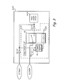
- FIG. 3 is a circuit diagram of the BPCU and/or the EMPC according to an embodiment of the present invention.
- the present invention is directed to a controller, such as a bus power control unit (BPCU) and/or emergency power controller (EMPC).
- the controller includes a power interrupt bridge circuit that monitors voltage on a DC bus that provides operational power to the controller, and compares the monitored DC voltage to a threshold. If the monitored DC voltage decreases below a threshold value, then the power interrupt bridge circuit supplies power to a DC output from an emergency DC power source for a defined period of time. In this way, the controller remains powered even during a loss of "normal" power.
- BPCU bus power control unit
- EMPC emergency power controller
- FIGS. 1A and 1B are circuit diagrams of a bus power control unit (BPCU) and emergency power controller (EMPC), respectively, employed as part of an electrical power distribution system (EPDS) according to an embodiment of the present invention.
- BPCU bus power control unit
- EMPC emergency power controller
- FIG. 1A illustrates BPCU 10 connected to receive "normal" operating power from DC power bus DC _ Input , and emergency power from DC emergency bus DC_EMER.
- BPCU 10 includes power interruption bridge circuit 12, diodes D1 and D2, power supply circuit 14, and micro-controller 16.
- power supplied by DC power bus DC _ Input is provided via diode D2 to power supply circuit 14, which supplies operational power to micro-controller 16.
- BPCU may receive power from a plurality of DC power buses, each of which is provided via a separate diode (creating a diode OR circuit) to power supply circuit 14.
- Power interruption bridge circuit 12 monitors the voltage provided by DC power bus DC_Input. In the event the monitored voltage falls below a threshold level, power interruption bridge circuit 12 operates to supply power from DC emergency bus DC_EMER through diode D1 to power supply circuit 14 for a defined period of time.
- power derived from the DC emergency bus DC_EMER is provided via one or more packs of batteries, referred to as a battery-direct bus.
- DC emergency bus DC_EMER may derive power from other emergency power sources.
- emergency power sources are only capable of providing a limited amount of power for a limited amount of time.
- power supply circuit 14 remains powered for a defined period of time based on power supplied by power interruption bridge circuit.
- power interruption bridge circuit prevents power from being supplied by DC emergency bus DC_EMER to power supply circuit 14 to prevent depletion of the DC emergency bus source (e.g., batteries).
- the DC emergency bus source e.g., batteries.
- BPCU remains operational and can transition the power distribution system from a normal operating mode to a "safe" or "emergency" operating mode.
- microcontroller 16 generates commands/instructions provided to contactors and/or relay drivers 18 to transition the power distribution system to the desired safe operating mode.
- This may include disconnecting non-essential buses and/or loads, and connecting essential buses and/or loads to emergency power sources such as a RAM Air Turbine (RAT) generator.
- RAT RAM Air Turbine
- the defined period of time power interruption bridge circuit supplies power to power supply circuit 14 is defined to ensure micro-controller 16 has sufficient time to generate the commands/instructions necessary to transition the power distribution system to the desired safe operating mode or emergency operating mode.
- FIG. 1B illustrates another type of controller, emergency power controller 20, in which the power interruption bridge circuit may be utilized.
- EMPC 20 is connected to receive "normal" operating power from DC power bus DC_Input, and emergency power from DC emergency bus DC_EMER.
- EMPC 20 includes power interruption bridge circuit 22, diodes D3 and D4, power supply circuit 24, and micro-controller 26.
- power supplied by DC power bus DC_Input is provided via diode D4 to power supply circuit 24, which supplies operational power to micro-controller 26.
- EMPC 20 may receive power from a plurality of DC power buses, each of which is provided via a separate diode (creating a diode OR circuit) to power supply circuit 24.
- Power interruption bridge circuit 22 monitors the voltage provided by DC power bus DC_Input. In the event the monitored voltage falls below a threshold level, power interruption bridge circuit 22 operates to supply power from DC emergency bus DC_EMER through diode D3 to power supply circuit 24 for a defined period of time.
- power derived from the DC emergency bus DC_EMER is provided via one or more packs of batteries, referred to as a battery-direct bus.
- DC emergency bus DC_EMER may derive power from other emergency power sources capable of providing power for limited periods of time (e.g., fuel cells, capacitors, super capacitors, etc.).. Typically, emergency power sources are only capable of providing a limited amount of power for a limited amount of time.
- power supply circuit 24 remains powered for a defined period of time based on power supplied by power interruption bridge circuit.
- power interruption bridge circuit 22 prevents power from being supplied by DC emergency bus DC_EMER to power supply circuit 24 to prevent depletion of the DC emergency bus source (e.g., batteries).
- the DC emergency bus source e.g., batteries.
- EMPC 20 remains operational and can transition the power distribution system from a normal operating mode to a "safe" or "emergency" operating mode. As described with respect to FIG.
- this may include generating commands/instructions provided to contractors and/or relay drivers 28 to transition the power distribution system to the desired safe operating mode. This may include disconnecting non-essential buses and/or loads, and connecting essential buses and/or loads to emergency power sources such as a RAM Air Turbine (RAT) generator.
- RAT RAM Air Turbine
- EMPC 20 is responsible for deploying RAM Air Turbine (RAT) generator 30 in response to an emergency loss of power.
- RAT RAM Air Turbine
- the defined period of time power interruption bridge circuit 22 maintains power to power supply circuit 24 is selected, in part, to ensure micro-controller 26 has sufficient time to deploy RAT 30.
- the defined period of time may also be selected based on time required to send command/instructions to contactors/relay drivers 28.
- FIG. 2 is a circuit diagram of BPCU 10 and/or EMPC 20 (referred to generically as "controller 10, 20") according to an embodiment of the present invention.
- Circuit elements previously described with respect to FIGS. 1A and 1B are described here with reference to both reference numbers.
- diode D2 shown in FIG. 1A
- diode D4 shown in FIG. 1B
- diode D2 is referred to here as diode D2
- diode D1 shown in FIG. 1A
- diode D3 shown in FIG. 1B
- power interruption bridge circuit 12 shown in FIG. 1A
- power interruption bridge circuit 22 shown in FIG. 1B
- power supply circuit 14 shown in FIG. 1A
- power supply circuit 24 shown in FIG. 1B
- power supply circuit 14, 24 is represented as power supply circuit 14, 24.
- FIG. 2 illustrates in additional detail the operation of power interruption bridge circuit 12, 22, which includes voltage monitoring/comparator 32, time constant selector 34, trigger circuit 36, and power switch 38.
- controller 10, 20 receives "normal" operational power from DC power bus DC_Input. Additionally, controller 10, 20 is connected to receive DC power from an emergency DC bus DC_EMER.
- Voltage monitoring/comparator circuit 32 monitors the voltage provided by DC bus DC_Input to detect low voltage conditions indicative of a potential fault. If the monitored voltage falls below the threshold value associated with or programmed into voltage monitoring/comparator circuit 32, a trigger signal is provided to the input of trigger circuit 36. In response, trigger circuit 36 turns ON power switch 38, creating a circuit path from the DC emergency bus DC_EMER through diode D1, D3 to power supply circuit 14, 24. In this way, controller 10, 20 remains powered despite the potential loss of power associated with DC power bus DC_Input.
- the duration of time trigger circuit 36 maintains power switch 38 in the On state is determined based on the value k stored by time constant selector 34, which is selected based on the particular application.
- the time value stored by time circuit 64 is selected to ensure that controller 10 remains powered for a duration of time sufficient to allow controller to provide emergency commands/instructions to the power distribution system, without fully depleting the power source associated with DC emergency bus DC_EMER.
- controller 10, 20 is an emergency power controller (EMPC) (as shown in FIG. 1B )
- the time constant k is selected to ensure controller 10, 20 receives operational power long enough to deploy RAT 30 (shown in FIG. 1B ).
- trigger circuit 36 turns power switch 38 Off, thereby disconnecting the DC emergency bus DC_EMER from supplying power to power supply circuit 14, 24.
- the expiration of the defined time period results in controller 10, 20 remaining unpowered until "normal" power sources are restored.
- the time period is defined such that at the end of the defined time period, emergency power such as that provided by RAT 30 (shown in FIG. 1B ) provides operational power to controller 10, 20.
- FIG. 3 is a circuit diagram of another embodiment of BPCU 10 and/or EMPC 20 (referred to generically as "controller 10, 20").
- controller 10, 20 circuit elements previously described with respect to FIGS. 1A and 1B are described here with reference to both reference numbers.
- diode D2 shown in FIG. 1A
- diode D4 shown in FIG. 1B
- diode D2 is referred to here as diode D2
- diode D1 shown in FIG. 1A
- diode D3 shown in FIG. 1B
- power interruption bridge circuit 12 shown in FIG. 1A
- power interruption bridge circuit 22 shown in FIG. 1B
- power supply circuit 14 shown in FIG. 1A
- power supply circuit 24 shown in FIG. 1B
- power supply circuit 14, 24 is represented as power supply circuit 14, 24.
- FIG. 3 illustrates in additional detail the operation of power interruption bridge circuit 12, 22, which includes voltage monitoring/comparator 42, time constant selector 44, trigger circuit 46, and relay 48.
- controller 10, 20 receives "normal" operational power from DC power bus DC_Input. Additionally, controller 10, 20 is connected to receive DC power from an emergency DC bus DC_EMER.
- voltage monitoring/comparator 42 monitors the voltage provided by DC power bus DC_Input to a threshold. If the monitored voltage falls below the threshold value associated with or programmed into voltage monitoring/comparator circuit 42, a trigger signal is provided to the input of trigger circuit 46. In response, trigger circuit 36 creates a circuit path from DC power bus DC_Input through trigger circuit 46 and relay 48 to ground. The resulting circuit path energizes relay 48, creating a circuit path between DC emergency bus DC_EMER and power supply circuit 14, 24. In this way, controller 10, 20 remains powered despite the potential loss of power associated with DC power bus DC_Input.
- the duration of time trigger circuit 46 maintains power switch 38 in the On state is determined based on the value k stored by time constant selector 44, which is selected based on the particular application. As discussed above with respect to FIG. 2 , the time value k stored by time constant selector 44 is selected to ensure that controller 10, 20 remains powered for a duration of time sufficient to allow controller to provide emergency commands/instructions to the power distribution system, without fully depleting the power source associated with DC emergency bus DC_EMER.
- trigger circuit 46 turns Off, thereby de-energizing relay 48 and disconnecting DC emergency power DC_EMER from supplying power to power supply circuit 14, 24.
- the duration of the time period is selected based on the application to allow controller 10, 20 to remain operational long enough to configure the system for emergency operation and/or deploy emergency power systems (e.g., RAT).
Landscapes
- Engineering & Computer Science (AREA)
- Business, Economics & Management (AREA)
- Emergency Management (AREA)
- Power Engineering (AREA)
- Aviation & Aerospace Engineering (AREA)
- Direct Current Feeding And Distribution (AREA)
Abstract
Description
- The present invention is related to power distribution systems and in particular to controllers employed in conjunction with power distribution systems.
- Aircraft applications rely on electrical power distribution systems to power a variety of critical systems on the aircraft. Controllers, such as bus power control units (BPCUs) and emergency power controllers (EMPCs), are responsible for monitoring and controlling the operation of the electrical power distribution system. For example, a BPCU is responsible for monitoring operation of the power distribution system and providing commands to selectively control the operation of various relays and/or contactors to selectively route power through various buses. Similarly, an EMPC is responsible for monitoring and providing command instructions to relays and/or contactors within the emergency power system to selectively route power to desired buses. In addition, the EMPC may also be responsible for deploying an RAM Air Turbine (RAT) generator for the purpose of generating emergency power.
- Both the BPCUs and the EMPCs require power to operation, typically derived from one or more of the power buses the units are charged with monitoring and controlling. A loss of power on all of the power buses results in an undesirable loss of operational power in the BPCUs and EMPCs.
- A controller is employed in conjunction with an electrical power distribution system (EPDS). The controller includes at least a first input for receiving DC power from a DC power bus and a power supply circuit connected to the first input to provide operational power to the controller. The controller further includes a power interrupt bridge circuit that monitors the voltage provided at the first input. In response to the monitored voltage being less than a threshold value, the power interrupt bridge circuit supplies power to the power supply circuit from a DC emergency source for a defined time period.
-
FIGS. 1A and 1B are circuit diagrams of a bus power control unit (BPCU) and emergency power controller (EMPC), respectively, according to an embodiment of the present invention. -
FIG. 2 is a circuit diagram of the BPCU and/or the EMPC according to an embodiment of the present invention. -
FIG. 3 is a circuit diagram of the BPCU and/or the EMPC according to an embodiment of the present invention. - The present invention is directed to a controller, such as a bus power control unit (BPCU) and/or emergency power controller (EMPC). The controller includes a power interrupt bridge circuit that monitors voltage on a DC bus that provides operational power to the controller, and compares the monitored DC voltage to a threshold. If the monitored DC voltage decreases below a threshold value, then the power interrupt bridge circuit supplies power to a DC output from an emergency DC power source for a defined period of time. In this way, the controller remains powered even during a loss of "normal" power.
-
FIGS. 1A and 1B are circuit diagrams of a bus power control unit (BPCU) and emergency power controller (EMPC), respectively, employed as part of an electrical power distribution system (EPDS) according to an embodiment of the present invention. -
FIG. 1A illustrates BPCU 10 connected to receive "normal" operating power from DC power bus DC_Input, and emergency power from DC emergency bus DC_EMER. BPCU 10 includes powerinterruption bridge circuit 12, diodes D1 and D2,power supply circuit 14, and micro-controller 16. During normal operation, power supplied by DC power bus DC_Input is provided via diode D2 topower supply circuit 14, which supplies operational power to micro-controller 16. In other embodiments, BPCU may receive power from a plurality of DC power buses, each of which is provided via a separate diode (creating a diode OR circuit) topower supply circuit 14. - Power
interruption bridge circuit 12 monitors the voltage provided by DC power bus DC_Input. In the event the monitored voltage falls below a threshold level, powerinterruption bridge circuit 12 operates to supply power from DC emergency bus DC_EMER through diode D1 topower supply circuit 14 for a defined period of time. In one embodiment, power derived from the DC emergency bus DC_EMER is provided via one or more packs of batteries, referred to as a battery-direct bus. In other embodiments, DC emergency bus DC_EMER may derive power from other emergency power sources. Typically, emergency power sources are only capable of providing a limited amount of power for a limited amount of time. - In this way, despite a loss of power supplied by DC power bus DC_Input,
power supply circuit 14 remains powered for a defined period of time based on power supplied by power interruption bridge circuit. At the end of the defined period of time, power interruption bridge circuit prevents power from being supplied by DC emergency bus DC_EMER topower supply circuit 14 to prevent depletion of the DC emergency bus source (e.g., batteries). During the time that emergency power is supplied by power interruption bridge circuit topower supply circuit 14, BPCU remains operational and can transition the power distribution system from a normal operating mode to a "safe" or "emergency" operating mode. In particular,microcontroller 16 generates commands/instructions provided to contactors and/orrelay drivers 18 to transition the power distribution system to the desired safe operating mode. This may include disconnecting non-essential buses and/or loads, and connecting essential buses and/or loads to emergency power sources such as a RAM Air Turbine (RAT) generator. In one embodiment, the defined period of time power interruption bridge circuit supplies power topower supply circuit 14 is defined to ensure micro-controller 16 has sufficient time to generate the commands/instructions necessary to transition the power distribution system to the desired safe operating mode or emergency operating mode. -
FIG. 1B illustrates another type of controller,emergency power controller 20, in which the power interruption bridge circuit may be utilized. In the embodiment shown inFIG. 1B , EMPC 20 is connected to receive "normal" operating power from DC power bus DC_Input, and emergency power from DC emergency bus DC_EMER. EMPC 20 includes powerinterruption bridge circuit 22, diodes D3 and D4,power supply circuit 24, and micro-controller 26. During normal operation, power supplied by DC power bus DC_Input is provided via diode D4 topower supply circuit 24, which supplies operational power to micro-controller 26. In other embodiments, EMPC 20 may receive power from a plurality of DC power buses, each of which is provided via a separate diode (creating a diode OR circuit) topower supply circuit 24. - Power
interruption bridge circuit 22 monitors the voltage provided by DC power bus DC_Input. In the event the monitored voltage falls below a threshold level, powerinterruption bridge circuit 22 operates to supply power from DC emergency bus DC_EMER through diode D3 topower supply circuit 24 for a defined period of time. In one embodiment, power derived from the DC emergency bus DC_EMER is provided via one or more packs of batteries, referred to as a battery-direct bus. In other embodiments, DC emergency bus DC_EMER may derive power from other emergency power sources capable of providing power for limited periods of time (e.g., fuel cells, capacitors, super capacitors, etc.).. Typically, emergency power sources are only capable of providing a limited amount of power for a limited amount of time. - In this way, despite a loss of power supplied by DC power bus DC_Input,
power supply circuit 24 remains powered for a defined period of time based on power supplied by power interruption bridge circuit. At the end of the defined period of time, powerinterruption bridge circuit 22 prevents power from being supplied by DC emergency bus DC_EMER topower supply circuit 24 to prevent depletion of the DC emergency bus source (e.g., batteries). During the time that emergency power is supplied by powerinterruption bridge circuit 22 topower supply circuit 24, EMPC 20 remains operational and can transition the power distribution system from a normal operating mode to a "safe" or "emergency" operating mode. As described with respect toFIG. 1A , this may include generating commands/instructions provided to contractors and/orrelay drivers 28 to transition the power distribution system to the desired safe operating mode. This may include disconnecting non-essential buses and/or loads, and connecting essential buses and/or loads to emergency power sources such as a RAM Air Turbine (RAT) generator. - In addition, in one embodiment EMPC 20 is responsible for deploying RAM Air Turbine (RAT)
generator 30 in response to an emergency loss of power. The defined period of time powerinterruption bridge circuit 22 maintains power topower supply circuit 24 is selected, in part, to ensure micro-controller 26 has sufficient time to deployRAT 30. The defined period of time may also be selected based on time required to send command/instructions to contactors/relay drivers 28. -
FIG. 2 is a circuit diagram ofBPCU 10 and/or EMPC 20 (referred to generically as "controller FIGS. 1A and 1B are described here with reference to both reference numbers. For example, diode D2 (shown inFIG. 1A ) and diode D4 (shown inFIG. 1B ) is referred to here as diode D2, D4. Likewise, diode D1 (shown inFIG. 1A ) and diode D3 (shown inFIG. 1B ) is represented as diode D1, D3, power interruption bridge circuit 12 (shown inFIG. 1A ) and power interruption bridge circuit 22 (shown inFIG. 1B ) is represented as powerinterruption bridge circuit FIG. 1A ), power supply circuit 24 (shown inFIG. 1B ) is represented aspower supply circuit - In particular,
FIG. 2 illustrates in additional detail the operation of powerinterruption bridge circuit comparator 32, timeconstant selector 34,trigger circuit 36, andpower switch 38. As described with respect toFIGS. 1A and 1B ,controller controller - Voltage monitoring/
comparator circuit 32 monitors the voltage provided by DC bus DC_Input to detect low voltage conditions indicative of a potential fault. If the monitored voltage falls below the threshold value associated with or programmed into voltage monitoring/comparator circuit 32, a trigger signal is provided to the input oftrigger circuit 36. In response,trigger circuit 36 turns ONpower switch 38, creating a circuit path from the DC emergency bus DC_EMER through diode D1, D3 topower supply circuit controller - The duration of
time trigger circuit 36 maintainspower switch 38 in the On state is determined based on the value k stored by timeconstant selector 34, which is selected based on the particular application. In general, the time value stored by time circuit 64 is selected to ensure thatcontroller 10 remains powered for a duration of time sufficient to allow controller to provide emergency commands/instructions to the power distribution system, without fully depleting the power source associated with DC emergency bus DC_EMER. For example, ifcontroller FIG. 1B ), the time constant k is selected to ensurecontroller FIG. 1B ). - At the expiration of the defined time period determined by the stored value k,
trigger circuit 36 turnspower switch 38 Off, thereby disconnecting the DC emergency bus DC_EMER from supplying power topower supply circuit controller FIG. 1B ) provides operational power tocontroller -
FIG. 3 is a circuit diagram of another embodiment ofBPCU 10 and/or EMPC 20 (referred to generically as "controller FIGS. 1A and 1B are described here with reference to both reference numbers. For example, diode D2 (shown inFIG. 1A ) and diode D4 (shown inFIG. 1B ) is referred to here as diode D2, D4. Likewise, diode D1 (shown inFIG. 1A ) and diode D3 (shown inFIG. 1B ) is represented as diode D1, D3, power interruption bridge circuit 12 (shown inFIG. 1A ) and power interruption bridge circuit 22 (shown inFIG. 1B ) is represented as powerinterruption bridge circuit FIG. 1A ), power supply circuit 24 (shown inFIG. 1B ) is represented aspower supply circuit - In particular,
FIG. 3 illustrates in additional detail the operation of powerinterruption bridge circuit comparator 42, timeconstant selector 44,trigger circuit 46, andrelay 48. As described with respect toFIGS. 1A and 1B ,controller controller - The operation of voltage monitoring/
comparator circuit 42, timeconstant selector 44, andtrigger circuit 46 operate in the same was as discussed with respect toFIG. 2 . However, power switch 38 (shown inFIG. 2 ) has been replaced withrelay 48. - Once again, voltage monitoring/
comparator 42 monitors the voltage provided by DC power bus DC_Input to a threshold. If the monitored voltage falls below the threshold value associated with or programmed into voltage monitoring/comparator circuit 42, a trigger signal is provided to the input oftrigger circuit 46. In response,trigger circuit 36 creates a circuit path from DC power bus DC_Input throughtrigger circuit 46 andrelay 48 to ground. The resulting circuit path energizesrelay 48, creating a circuit path between DC emergency bus DC_EMER andpower supply circuit controller - The duration of
time trigger circuit 46 maintainspower switch 38 in the On state is determined based on the value k stored by timeconstant selector 44, which is selected based on the particular application. As discussed above with respect toFIG. 2 , the time value k stored by timeconstant selector 44 is selected to ensure thatcontroller - At the expiration of the defined time period determined by the stored value k,
trigger circuit 46 turns Off, thereby de-energizingrelay 48 and disconnecting DC emergency power DC_EMER from supplying power topower supply circuit FIG. 2 , the duration of the time period is selected based on the application to allowcontroller - While the invention has been described with reference to an exemplary embodiment(s), it will be understood by those skilled in the art that various changes may be made and equivalents may be substituted for elements thereof without departing from the scope of the invention. In addition, many modifications may be made to adapt a particular situation or material to the teachings of the invention without departing from the essential scope thereof. Therefore, it is intended that the invention not be limited to the particular embodiment(s) disclosed, but that the invention will include all embodiments falling within the scope of the appended claims.
Claims (15)
- A controller for providing control commands associated with at least one of an alternating current (AC) power bus and a direct current (DC) power bus, the controller comprising:at least a first input for receiving DC power from a DC power bus;a power supply circuit connected to the first input to receive DC power that is used to power the controller; anda power interrupt bridge circuit connected to monitor a voltage provided by the DC power bus and in response to the monitored voltage being less than a threshold value supplies power to the power supply circuit from a DC emergency power source for only a defined time period to ensure the controller remains powered.
- The controller of claim 1, wherein the power interrupt bridge circuit includes:a monitoring/comparator circuit that monitors the voltage provided by the DC power bus and provides a trigger signal when the monitored voltage is less than a threshold value;a relay circuit having a first state and a second state, wherein the relay circuit connects the DC emergency power source to the power supply circuit in the first state and prevents connection of the DC emergency power source to the power supply circuit in the second state; anda trigger circuit connected to place the relay circuit in the first state in response to the trigger signal provided by the monitoring/comparator circuit and place the relay circuit in the second state at the expiration of the defined time period.
- The controller of claim 1, wherein the power interrupt bridge circuit includes:a monitoring/comparator circuit that monitors the voltage provided by the DC power bus and provides a trigger signal when the monitored voltage is less than a threshold value;a solid-state switch having a first state and a second state, wherein the solid-state switch connects the DC emergency source to the power supply circuit in the first state and prevents connection of the DC emergency power source to the power supply circuit in the second state; anda trigger circuit connected to place the solid-state switch in the first state in response to the trigger signal provided by the monitoring/comparator circuit and place the solid-state switch in the second state at the expiration of the defined time period.
- The controller of claim 1, 2 or 3, wherein the defined time period is less than a time required to deplete the DC emergency power source.
- The controller of claim 1, 2, 3 or 4, wherein the DC emergency power source is selected from a group consisting of at least one of the following: a battery, a capacitor, and a fuel cell.
- The controller of any preceding claim, wherein the controller is a bus power control unit (BPCU) that provides commands to one or more relays and/or contactors.
- The controller of any preceding claim, wherein the controller is employed in conjunction with a RAM air turbine (RAT) and provides deployment instructions to the RAT; preferably wherein the defined time period is greater than a time required to deploy the RAT in response to a detected loss of power.
- The controller of any preceding claim, wherein the controller is an emergency power control unit (EMPC).
- A power distribution system comprising:a direct current (DC) power bus;an emergency DC power bus;a RAM air turbine (RAT) generator that is deployed to generate emergency power;an emergency power controller (EMPC) as claimed in any of claims 1 to 6.
- The power distribution system of claim 9, wherein the defined time period is greater than a time required to deploy the RAT in response to a detected loss of power.
- A method of supplying power to a controller during emergency operations, the method comprising:monitoring a voltage associated with operational power provided to the controller;comparing the monitored voltage to a threshold value to detect a low voltage condition;connecting an emergency DC power supply to supply operational power to the controller in response to the monitored voltage being less than the threshold value; anddisconnecting the emergency DC power supply from the controller upon expiration of a defined time period.
- The method of claim 11, wherein the controller is an emergency power controller (EMPC) employed in conjunction with an electric power center (EPC), wherein the EMPC utilizes power received from the emergency DC power supply to deploy a RAM air turbine (RAT) generator for generating emergency power.
- The method of claim 12, wherein the defined time period is greater than a time required by the EMPC to deploy the RAT in response to a detected loss of power.
- The method of claim 11, 12 or 13, wherein the defined time period is less than a time required to deplete the emergency DC power supply.
- The method of claim 11, 12, 13 or 14, wherein the controller is a bus power control unit (BPCU), wherein the BPCU utilizes power received from the emergency DC power supply to configure relays and/or contactors associated with a power distribution system to a desired state for emergency operation.
Applications Claiming Priority (1)
| Application Number | Priority Date | Filing Date | Title |
|---|---|---|---|
| US13/440,060 US9789973B2 (en) | 2012-04-05 | 2012-04-05 | Power interruption bridge circuit |
Publications (2)
| Publication Number | Publication Date |
|---|---|
| EP2648322A1 true EP2648322A1 (en) | 2013-10-09 |
| EP2648322B1 EP2648322B1 (en) | 2015-01-14 |
Family
ID=47632883
Family Applications (1)
| Application Number | Title | Priority Date | Filing Date |
|---|---|---|---|
| EP20130153421 Active EP2648322B1 (en) | 2012-04-05 | 2013-01-31 | Power interruption bridge circuit |
Country Status (2)
| Country | Link |
|---|---|
| US (1) | US9789973B2 (en) |
| EP (1) | EP2648322B1 (en) |
Cited By (1)
| Publication number | Priority date | Publication date | Assignee | Title |
|---|---|---|---|---|
| EP4280407A1 (en) * | 2022-05-20 | 2023-11-22 | Hamilton Sundstrand Corporation | Direct current bus control scheme |
Families Citing this family (10)
| Publication number | Priority date | Publication date | Assignee | Title |
|---|---|---|---|---|
| EP3148032B1 (en) * | 2015-09-28 | 2018-03-28 | GE Energy Power Conversion Technology Ltd | Power supply system of a set of loads connected in parallel to a dc power bus |
| JP7027027B2 (en) * | 2016-03-17 | 2022-03-01 | キヤノン株式会社 | Information processing equipment, control methods, and their programs |
| US10469250B2 (en) * | 2017-12-22 | 2019-11-05 | Max Adel Rady | Physical item mapping to blockchain framework |
| US10703502B2 (en) * | 2018-03-20 | 2020-07-07 | Hamilton Sunstrand Corporation | Emergency power system with energy storage device |
| US10322815B1 (en) | 2018-03-22 | 2019-06-18 | Hamilton Sundstrand Corporation | Stored electrical energy assisted ram air turbine (RAT) system |
| US11424642B2 (en) | 2019-03-22 | 2022-08-23 | Hamilton Sundstrand Corporation | Solid switch power distribution controller with storage device backup |
| US11616366B2 (en) | 2020-03-12 | 2023-03-28 | Hamilton Sundstrand Corporation | AC essential bus delta current and over current protection scheme |
| US11383855B2 (en) | 2020-03-18 | 2022-07-12 | Hamilton Sundstrand Corporation | DC bus voltage input into RAT auto-deploy |
| US20230324936A1 (en) * | 2022-04-12 | 2023-10-12 | Schweitzer Engineering Laboratories, Inc. | Direct current monitoring using a centralized protection and control system |
| US20250062636A1 (en) * | 2023-08-15 | 2025-02-20 | Air Products And Chemicals, Inc. | Method and System for Emergency Backup Power |
Citations (2)
| Publication number | Priority date | Publication date | Assignee | Title |
|---|---|---|---|---|
| US20060061213A1 (en) * | 2004-08-24 | 2006-03-23 | Honeywell International | Electrical starting, generation, conversion and distribution system architecture for a more electric vehicle |
| US20080155294A1 (en) * | 2006-12-22 | 2008-06-26 | Hideo Kikuchi | Power supply device, image forming apparatus, and power supply method |
Family Cites Families (17)
| Publication number | Priority date | Publication date | Assignee | Title |
|---|---|---|---|---|
| AU4408296A (en) * | 1994-11-28 | 1996-06-19 | Analogic Corporation | Ups for medical imaging system |
| AU2432701A (en) * | 1999-12-16 | 2001-06-25 | Mcandrews Enterprises Inc. | Spare bus power plant |
| JP2002025790A (en) * | 2000-07-12 | 2002-01-25 | Koito Mfg Co Ltd | Discharge lamp lighting circuit |
| US7016171B2 (en) * | 2001-02-01 | 2006-03-21 | Hydro-Aire, Inc. | Current fault detector and circuit interrupter and packaging thereof |
| MXPA02007840A (en) * | 2001-08-15 | 2012-02-22 | Eltech Systems Corp | Anodic protection systems and methods. |
| US6862165B2 (en) * | 2003-06-06 | 2005-03-01 | Honeywell International Inc. | Method and apparatus for valve control |
| US7689852B2 (en) * | 2003-09-12 | 2010-03-30 | Broadcom Corporation | Method and system for providing power management for an integrated gigabit ethernet controller |
| JP4210200B2 (en) * | 2003-11-11 | 2009-01-14 | 本田技研工業株式会社 | Vehicle power supply system |
| TWI298123B (en) * | 2005-07-11 | 2008-06-21 | Asrock Inc | Dc uninterruptible power supply and computer device using the same |
| US7750501B2 (en) * | 2005-10-27 | 2010-07-06 | Continental Automotive Systems Us, Inc. | System and method of over voltage control for a power system |
| US7872368B2 (en) * | 2008-10-24 | 2011-01-18 | The Boeing Company | Intelligent energy management architecture |
| US8829707B2 (en) * | 2010-07-15 | 2014-09-09 | Hamilton Sundstrand Corporation | Methods for aircraft emergency power management |
| US8344546B2 (en) * | 2010-07-16 | 2013-01-01 | Facebook, Inc. | Power supply unit directly connected to backup direct current power source |
| GB201015510D0 (en) * | 2010-09-16 | 2010-10-27 | Goodrich Actuation Systems Sas | Power supply system |
| US8738268B2 (en) * | 2011-03-10 | 2014-05-27 | The Boeing Company | Vehicle electrical power management and distribution |
| US8820677B2 (en) * | 2011-06-18 | 2014-09-02 | Jason A. Houdek | Aircraft power systems and methods |
| US20130181448A1 (en) * | 2012-01-17 | 2013-07-18 | Hamilton Sundstrand Corporation | Electric actuators in aircraft systems |
-
2012
- 2012-04-05 US US13/440,060 patent/US9789973B2/en active Active
-
2013
- 2013-01-31 EP EP20130153421 patent/EP2648322B1/en active Active
Patent Citations (2)
| Publication number | Priority date | Publication date | Assignee | Title |
|---|---|---|---|---|
| US20060061213A1 (en) * | 2004-08-24 | 2006-03-23 | Honeywell International | Electrical starting, generation, conversion and distribution system architecture for a more electric vehicle |
| US20080155294A1 (en) * | 2006-12-22 | 2008-06-26 | Hideo Kikuchi | Power supply device, image forming apparatus, and power supply method |
Cited By (2)
| Publication number | Priority date | Publication date | Assignee | Title |
|---|---|---|---|---|
| EP4280407A1 (en) * | 2022-05-20 | 2023-11-22 | Hamilton Sundstrand Corporation | Direct current bus control scheme |
| US12107409B2 (en) | 2022-05-20 | 2024-10-01 | Hamilton Sundstrand Corporation | Direct current bus control scheme |
Also Published As
| Publication number | Publication date |
|---|---|
| EP2648322B1 (en) | 2015-01-14 |
| US9789973B2 (en) | 2017-10-17 |
| US20130264878A1 (en) | 2013-10-10 |
Similar Documents
| Publication | Publication Date | Title |
|---|---|---|
| US9789973B2 (en) | Power interruption bridge circuit | |
| US10464441B2 (en) | Charging facility and energy management method for charging facility | |
| US10003200B2 (en) | Decentralized module-based DC data center | |
| EP3487035B1 (en) | Power supply system and method | |
| EP2670015B1 (en) | Power control device and power control method | |
| US10153641B2 (en) | Extending black-start availability using energy storage systems | |
| CN102336275B (en) | For the method for airplane emergency electrical management | |
| US9083201B2 (en) | Load shedding circuit for RAM air turbines | |
| US9935494B2 (en) | Elevator power supply for inverter controller | |
| CN115051423B (en) | Charge-discharge control device | |
| EP2768110A1 (en) | Battery charging system | |
| US11708171B2 (en) | Power distribution system and power distribution method | |
| US9713995B2 (en) | Power conversion device | |
| CA2982747C (en) | Emergency dimming apparatus | |
| EP4475386A2 (en) | Arrangement of converters and fast switches to provide bess & ups combined function | |
| EP3713032A1 (en) | Solid switch power distribution controller with storage device backup | |
| US20130214589A1 (en) | Ram air turbine smoke isolation | |
| KR101427680B1 (en) | High efficiency power supply for managing power of data center and method for supplying power using thereof | |
| US12107409B2 (en) | Direct current bus control scheme | |
| US11296506B2 (en) | Bidirectional charging panel | |
| KR20140088503A (en) | High efficiency power supply for managing power of data center and method for supplying power using thereof |
Legal Events
| Date | Code | Title | Description |
|---|---|---|---|
| PUAI | Public reference made under article 153(3) epc to a published international application that has entered the european phase |
Free format text: ORIGINAL CODE: 0009012 |
|
| AK | Designated contracting states |
Kind code of ref document: A1 Designated state(s): AL AT BE BG CH CY CZ DE DK EE ES FI FR GB GR HR HU IE IS IT LI LT LU LV MC MK MT NL NO PL PT RO RS SE SI SK SM TR |
|
| AX | Request for extension of the european patent |
Extension state: BA ME |
|
| 17P | Request for examination filed |
Effective date: 20140408 |
|
| RBV | Designated contracting states (corrected) |
Designated state(s): AL AT BE BG CH CY CZ DE DK EE ES FI FR GB GR HR HU IE IS IT LI LT LU LV MC MK MT NL NO PL PT RO RS SE SI SK SM TR |
|
| RIC1 | Information provided on ipc code assigned before grant |
Ipc: H02M 1/32 20070101AFI20140514BHEP Ipc: H02J 9/06 20060101ALI20140514BHEP Ipc: B64D 41/00 20060101ALI20140514BHEP |
|
| GRAP | Despatch of communication of intention to grant a patent |
Free format text: ORIGINAL CODE: EPIDOSNIGR1 |
|
| INTG | Intention to grant announced |
Effective date: 20140729 |
|
| GRAS | Grant fee paid |
Free format text: ORIGINAL CODE: EPIDOSNIGR3 |
|
| GRAA | (expected) grant |
Free format text: ORIGINAL CODE: 0009210 |
|
| AK | Designated contracting states |
Kind code of ref document: B1 Designated state(s): AL AT BE BG CH CY CZ DE DK EE ES FI FR GB GR HR HU IE IS IT LI LT LU LV MC MK MT NL NO PL PT RO RS SE SI SK SM TR |
|
| REG | Reference to a national code |
Ref country code: GB Ref legal event code: FG4D |
|
| REG | Reference to a national code |
Ref country code: CH Ref legal event code: EP |
|
| REG | Reference to a national code |
Ref country code: IE Ref legal event code: FG4D |
|
| REG | Reference to a national code |
Ref country code: AT Ref legal event code: REF Ref document number: 707476 Country of ref document: AT Kind code of ref document: T Effective date: 20150215 |
|
| REG | Reference to a national code |
Ref country code: DE Ref legal event code: R096 Ref document number: 602013000818 Country of ref document: DE Effective date: 20150226 |
|
| REG | Reference to a national code |
Ref country code: NL Ref legal event code: VDEP Effective date: 20150114 |
|
| REG | Reference to a national code |
Ref country code: AT Ref legal event code: MK05 Ref document number: 707476 Country of ref document: AT Kind code of ref document: T Effective date: 20150114 |
|
| REG | Reference to a national code |
Ref country code: LT Ref legal event code: MG4D |
|
| PG25 | Lapsed in a contracting state [announced via postgrant information from national office to epo] |
Ref country code: BE Free format text: LAPSE BECAUSE OF NON-PAYMENT OF DUE FEES Effective date: 20150131 |
|
| PG25 | Lapsed in a contracting state [announced via postgrant information from national office to epo] |
Ref country code: FI Free format text: LAPSE BECAUSE OF FAILURE TO SUBMIT A TRANSLATION OF THE DESCRIPTION OR TO PAY THE FEE WITHIN THE PRESCRIBED TIME-LIMIT Effective date: 20150114 Ref country code: BG Free format text: LAPSE BECAUSE OF FAILURE TO SUBMIT A TRANSLATION OF THE DESCRIPTION OR TO PAY THE FEE WITHIN THE PRESCRIBED TIME-LIMIT Effective date: 20150414 Ref country code: LT Free format text: LAPSE BECAUSE OF FAILURE TO SUBMIT A TRANSLATION OF THE DESCRIPTION OR TO PAY THE FEE WITHIN THE PRESCRIBED TIME-LIMIT Effective date: 20150114 Ref country code: SE Free format text: LAPSE BECAUSE OF FAILURE TO SUBMIT A TRANSLATION OF THE DESCRIPTION OR TO PAY THE FEE WITHIN THE PRESCRIBED TIME-LIMIT Effective date: 20150114 Ref country code: NO Free format text: LAPSE BECAUSE OF FAILURE TO SUBMIT A TRANSLATION OF THE DESCRIPTION OR TO PAY THE FEE WITHIN THE PRESCRIBED TIME-LIMIT Effective date: 20150414 Ref country code: HR Free format text: LAPSE BECAUSE OF FAILURE TO SUBMIT A TRANSLATION OF THE DESCRIPTION OR TO PAY THE FEE WITHIN THE PRESCRIBED TIME-LIMIT Effective date: 20150114 Ref country code: ES Free format text: LAPSE BECAUSE OF FAILURE TO SUBMIT A TRANSLATION OF THE DESCRIPTION OR TO PAY THE FEE WITHIN THE PRESCRIBED TIME-LIMIT Effective date: 20150114 |
|
| PG25 | Lapsed in a contracting state [announced via postgrant information from national office to epo] |
Ref country code: GR Free format text: LAPSE BECAUSE OF FAILURE TO SUBMIT A TRANSLATION OF THE DESCRIPTION OR TO PAY THE FEE WITHIN THE PRESCRIBED TIME-LIMIT Effective date: 20150415 Ref country code: LV Free format text: LAPSE BECAUSE OF FAILURE TO SUBMIT A TRANSLATION OF THE DESCRIPTION OR TO PAY THE FEE WITHIN THE PRESCRIBED TIME-LIMIT Effective date: 20150114 Ref country code: RS Free format text: LAPSE BECAUSE OF FAILURE TO SUBMIT A TRANSLATION OF THE DESCRIPTION OR TO PAY THE FEE WITHIN THE PRESCRIBED TIME-LIMIT Effective date: 20150114 Ref country code: IS Free format text: LAPSE BECAUSE OF FAILURE TO SUBMIT A TRANSLATION OF THE DESCRIPTION OR TO PAY THE FEE WITHIN THE PRESCRIBED TIME-LIMIT Effective date: 20150514 Ref country code: PL Free format text: LAPSE BECAUSE OF FAILURE TO SUBMIT A TRANSLATION OF THE DESCRIPTION OR TO PAY THE FEE WITHIN THE PRESCRIBED TIME-LIMIT Effective date: 20150114 Ref country code: AT Free format text: LAPSE BECAUSE OF FAILURE TO SUBMIT A TRANSLATION OF THE DESCRIPTION OR TO PAY THE FEE WITHIN THE PRESCRIBED TIME-LIMIT Effective date: 20150114 Ref country code: NL Free format text: LAPSE BECAUSE OF FAILURE TO SUBMIT A TRANSLATION OF THE DESCRIPTION OR TO PAY THE FEE WITHIN THE PRESCRIBED TIME-LIMIT Effective date: 20150114 |
|
| REG | Reference to a national code |
Ref country code: DE Ref legal event code: R097 Ref document number: 602013000818 Country of ref document: DE |
|
| PG25 | Lapsed in a contracting state [announced via postgrant information from national office to epo] |
Ref country code: MC Free format text: LAPSE BECAUSE OF FAILURE TO SUBMIT A TRANSLATION OF THE DESCRIPTION OR TO PAY THE FEE WITHIN THE PRESCRIBED TIME-LIMIT Effective date: 20150114 Ref country code: SK Free format text: LAPSE BECAUSE OF FAILURE TO SUBMIT A TRANSLATION OF THE DESCRIPTION OR TO PAY THE FEE WITHIN THE PRESCRIBED TIME-LIMIT Effective date: 20150114 Ref country code: CZ Free format text: LAPSE BECAUSE OF FAILURE TO SUBMIT A TRANSLATION OF THE DESCRIPTION OR TO PAY THE FEE WITHIN THE PRESCRIBED TIME-LIMIT Effective date: 20150114 Ref country code: RO Free format text: LAPSE BECAUSE OF FAILURE TO SUBMIT A TRANSLATION OF THE DESCRIPTION OR TO PAY THE FEE WITHIN THE PRESCRIBED TIME-LIMIT Effective date: 20150114 Ref country code: DK Free format text: LAPSE BECAUSE OF FAILURE TO SUBMIT A TRANSLATION OF THE DESCRIPTION OR TO PAY THE FEE WITHIN THE PRESCRIBED TIME-LIMIT Effective date: 20150114 Ref country code: EE Free format text: LAPSE BECAUSE OF FAILURE TO SUBMIT A TRANSLATION OF THE DESCRIPTION OR TO PAY THE FEE WITHIN THE PRESCRIBED TIME-LIMIT Effective date: 20150114 |
|
| REG | Reference to a national code |
Ref country code: IE Ref legal event code: MM4A |
|
| PLBE | No opposition filed within time limit |
Free format text: ORIGINAL CODE: 0009261 |
|
| STAA | Information on the status of an ep patent application or granted ep patent |
Free format text: STATUS: NO OPPOSITION FILED WITHIN TIME LIMIT |
|
| REG | Reference to a national code |
Ref country code: FR Ref legal event code: PLFP Year of fee payment: 4 |
|
| 26N | No opposition filed |
Effective date: 20151015 |
|
| PG25 | Lapsed in a contracting state [announced via postgrant information from national office to epo] |
Ref country code: IT Free format text: LAPSE BECAUSE OF FAILURE TO SUBMIT A TRANSLATION OF THE DESCRIPTION OR TO PAY THE FEE WITHIN THE PRESCRIBED TIME-LIMIT Effective date: 20150114 |
|
| PG25 | Lapsed in a contracting state [announced via postgrant information from national office to epo] |
Ref country code: IE Free format text: LAPSE BECAUSE OF NON-PAYMENT OF DUE FEES Effective date: 20150131 |
|
| PG25 | Lapsed in a contracting state [announced via postgrant information from national office to epo] |
Ref country code: SI Free format text: LAPSE BECAUSE OF FAILURE TO SUBMIT A TRANSLATION OF THE DESCRIPTION OR TO PAY THE FEE WITHIN THE PRESCRIBED TIME-LIMIT Effective date: 20150114 |
|
| PG25 | Lapsed in a contracting state [announced via postgrant information from national office to epo] |
Ref country code: BE Free format text: LAPSE BECAUSE OF FAILURE TO SUBMIT A TRANSLATION OF THE DESCRIPTION OR TO PAY THE FEE WITHIN THE PRESCRIBED TIME-LIMIT Effective date: 20150114 |
|
| REG | Reference to a national code |
Ref country code: CH Ref legal event code: PL |
|
| PG25 | Lapsed in a contracting state [announced via postgrant information from national office to epo] |
Ref country code: CH Free format text: LAPSE BECAUSE OF NON-PAYMENT OF DUE FEES Effective date: 20160131 Ref country code: LI Free format text: LAPSE BECAUSE OF NON-PAYMENT OF DUE FEES Effective date: 20160131 |
|
| REG | Reference to a national code |
Ref country code: FR Ref legal event code: PLFP Year of fee payment: 5 |
|
| PG25 | Lapsed in a contracting state [announced via postgrant information from national office to epo] |
Ref country code: MT Free format text: LAPSE BECAUSE OF FAILURE TO SUBMIT A TRANSLATION OF THE DESCRIPTION OR TO PAY THE FEE WITHIN THE PRESCRIBED TIME-LIMIT Effective date: 20150114 |
|
| PG25 | Lapsed in a contracting state [announced via postgrant information from national office to epo] |
Ref country code: HU Free format text: LAPSE BECAUSE OF FAILURE TO SUBMIT A TRANSLATION OF THE DESCRIPTION OR TO PAY THE FEE WITHIN THE PRESCRIBED TIME-LIMIT; INVALID AB INITIO Effective date: 20130131 |
|
| PG25 | Lapsed in a contracting state [announced via postgrant information from national office to epo] |
Ref country code: CY Free format text: LAPSE BECAUSE OF FAILURE TO SUBMIT A TRANSLATION OF THE DESCRIPTION OR TO PAY THE FEE WITHIN THE PRESCRIBED TIME-LIMIT Effective date: 20150114 |
|
| REG | Reference to a national code |
Ref country code: DE Ref legal event code: R082 Ref document number: 602013000818 Country of ref document: DE Representative=s name: SCHMITT-NILSON SCHRAUD WAIBEL WOHLFROM PATENTA, DE |
|
| PG25 | Lapsed in a contracting state [announced via postgrant information from national office to epo] |
Ref country code: TR Free format text: LAPSE BECAUSE OF FAILURE TO SUBMIT A TRANSLATION OF THE DESCRIPTION OR TO PAY THE FEE WITHIN THE PRESCRIBED TIME-LIMIT Effective date: 20150114 |
|
| PG25 | Lapsed in a contracting state [announced via postgrant information from national office to epo] |
Ref country code: LU Free format text: LAPSE BECAUSE OF NON-PAYMENT OF DUE FEES Effective date: 20150131 |
|
| REG | Reference to a national code |
Ref country code: FR Ref legal event code: PLFP Year of fee payment: 6 |
|
| PG25 | Lapsed in a contracting state [announced via postgrant information from national office to epo] |
Ref country code: SM Free format text: LAPSE BECAUSE OF FAILURE TO SUBMIT A TRANSLATION OF THE DESCRIPTION OR TO PAY THE FEE WITHIN THE PRESCRIBED TIME-LIMIT Effective date: 20150114 |
|
| PG25 | Lapsed in a contracting state [announced via postgrant information from national office to epo] |
Ref country code: MK Free format text: LAPSE BECAUSE OF FAILURE TO SUBMIT A TRANSLATION OF THE DESCRIPTION OR TO PAY THE FEE WITHIN THE PRESCRIBED TIME-LIMIT Effective date: 20150114 Ref country code: PT Free format text: LAPSE BECAUSE OF FAILURE TO SUBMIT A TRANSLATION OF THE DESCRIPTION OR TO PAY THE FEE WITHIN THE PRESCRIBED TIME-LIMIT Effective date: 20150114 |
|
| PG25 | Lapsed in a contracting state [announced via postgrant information from national office to epo] |
Ref country code: AL Free format text: LAPSE BECAUSE OF FAILURE TO SUBMIT A TRANSLATION OF THE DESCRIPTION OR TO PAY THE FEE WITHIN THE PRESCRIBED TIME-LIMIT Effective date: 20150114 |
|
| P01 | Opt-out of the competence of the unified patent court (upc) registered |
Effective date: 20230522 |
|
| PGFP | Annual fee paid to national office [announced via postgrant information from national office to epo] |
Ref country code: GB Payment date: 20251219 Year of fee payment: 14 |
|
| PGFP | Annual fee paid to national office [announced via postgrant information from national office to epo] |
Ref country code: FR Payment date: 20251218 Year of fee payment: 14 |
|
| PGFP | Annual fee paid to national office [announced via postgrant information from national office to epo] |
Ref country code: DE Payment date: 20251217 Year of fee payment: 14 |