EP2648190A1 - Device for generating a high temperature gradient in a nuclear fuel sample - Google Patents
Device for generating a high temperature gradient in a nuclear fuel sample Download PDFInfo
- Publication number
- EP2648190A1 EP2648190A1 EP13161851.4A EP13161851A EP2648190A1 EP 2648190 A1 EP2648190 A1 EP 2648190A1 EP 13161851 A EP13161851 A EP 13161851A EP 2648190 A1 EP2648190 A1 EP 2648190A1
- Authority
- EP
- European Patent Office
- Prior art keywords
- assembly according
- sample
- pellet
- resistor
- fuel
- Prior art date
- Legal status (The legal status is an assumption and is not a legal conclusion. Google has not performed a legal analysis and makes no representation as to the accuracy of the status listed.)
- Granted
Links
Images


Classifications
-
- G—PHYSICS
- G21—NUCLEAR PHYSICS; NUCLEAR ENGINEERING
- G21C—NUCLEAR REACTORS
- G21C17/00—Monitoring; Testing ; Maintaining
- G21C17/10—Structural combination of fuel element, control rod, reactor core, or moderator structure with sensitive instruments, e.g. for measuring radioactivity, strain
- G21C17/112—Measuring temperature
-
- G—PHYSICS
- G21—NUCLEAR PHYSICS; NUCLEAR ENGINEERING
- G21C—NUCLEAR REACTORS
- G21C21/00—Apparatus or processes specially adapted to the manufacture of reactors or parts thereof
- G21C21/02—Manufacture of fuel elements or breeder elements contained in non-active casings
-
- G—PHYSICS
- G21—NUCLEAR PHYSICS; NUCLEAR ENGINEERING
- G21C—NUCLEAR REACTORS
- G21C17/00—Monitoring; Testing ; Maintaining
- G21C17/06—Devices or arrangements for monitoring or testing fuel or fuel elements outside the reactor core, e.g. for burn-up, for contamination
-
- G—PHYSICS
- G21—NUCLEAR PHYSICS; NUCLEAR ENGINEERING
- G21C—NUCLEAR REACTORS
- G21C3/00—Reactor fuel elements and their assemblies; Selection of substances for use as reactor fuel elements
- G21C3/02—Fuel elements
- G21C3/04—Constructional details
- G21C3/16—Details of the construction within the casing
- G21C3/20—Details of the construction within the casing with coating on fuel or on inside of casing; with non-active interlayer between casing and active material with multiple casings or multiple active layers
-
- Y—GENERAL TAGGING OF NEW TECHNOLOGICAL DEVELOPMENTS; GENERAL TAGGING OF CROSS-SECTIONAL TECHNOLOGIES SPANNING OVER SEVERAL SECTIONS OF THE IPC; TECHNICAL SUBJECTS COVERED BY FORMER USPC CROSS-REFERENCE ART COLLECTIONS [XRACs] AND DIGESTS
- Y02—TECHNOLOGIES OR APPLICATIONS FOR MITIGATION OR ADAPTATION AGAINST CLIMATE CHANGE
- Y02E—REDUCTION OF GREENHOUSE GAS [GHG] EMISSIONS, RELATED TO ENERGY GENERATION, TRANSMISSION OR DISTRIBUTION
- Y02E30/00—Energy generation of nuclear origin
- Y02E30/30—Nuclear fission reactors
Definitions
- the field of the invention is that of heating devices comprising the controlled generation of thermal gradient within a sample, particularly finding a particular interest for controlling and characterizing the behavior of nuclear fuels under a thermal gradient and which can be used in a high-temperature laboratory. nuclear activity.
- MOX fuel for "Oxide Mixes" containing plutonium dioxide PuO 2 and uranium dioxide UO 2 , made from about 7% plutonium and 93% depleted uranium, knowledge of the transfer phenomena of fission products, especially gaseous, within the fuel and loosening conditions, needs to be deepened.
- the fuels are in the form of UO 2 pellets or (U, Pu) O 2 stacked in a zirconium alloy sheath.
- UO 2 pellets or (U, Pu) O 2 stacked in a zirconium alloy sheath.
- IPG Interaction Pastille Sheath
- the fuel can undergo a large and rapid temperature increment compared to its normal situation. This thermal transient causes an increase in the stress of the pellet on the sheath and can lead to its rupture.
- the sheath is the first containment barrier to fission products, it is essential to ensure its integrity and therefore to better understand these IPG phenomena.
- DURANCE Device simulating the composition under thermal combustion of the Combustibles.
- This DURANCE device comprises a thermal gradient within the sample, provided by a heating chuck inserted in the core and a system of insulating materials cooled by an auxiliary device.
- the amplitude of the thermal gradient between the core of the sample and the outer face of the sheath is, therefore, driven by the core temperature level and the nature, thickness and external temperature of the insulators.
- the Applicant has sought to develop a device to reproduce and control the amplitude of the thermal gradient undergone by the nuclear fuel during certain accident situations and this thanks to a small-scale installation easily adaptable to the treatment furnaces thermal devices used by the laboratory in a high-activity cell and this by freeing itself from any water circulation (pressurized or not) in contact with the fuel element, the heating being provided by induction.
- the development of an induction heating system for two to three fuel pellets providing a heat flow from the inside to the outside of them makes it possible to represent the temperature profile observed in the reactor.
- One of the important objectives of the device proposed in the present invention is therefore to reproduce and control the amplitude of the thermal gradient undergone by a nuclear fuel during certain accident situations and this thanks to a reduced-size installation easily adaptable to heat treatment furnaces used by a laboratory in a high-activity cell and this by avoiding any circulation of water (pressurized or not) in contact with the fuel element, the heating being provided by induction.
- the device of the present invention constitutes in particular a solution that can make it possible to bring the fuel to a central temperature of up to 2000 ° C., or even more, and stabilize the sheath temperature at around 350 ° C. +/- 50 ° C. on typically three pellets of combustible.
- the first induction means comprise at least a first coil.
- the second means comprise at least one second coil.
- the enclosure is a quartz tube.
- the sample comprises a ceramic pellet may be Al 2 O 3 , or ZrO 2 or a nuclear fuel pellet may be UO 2 or MOX.
- the sample comprises a metal sheath on the periphery of said wafer and in direct contact with said wafer.
- it further comprises a thermal insulating element at the periphery of said sample.
- the sample comprises a ceramic pellet, the insulator being made of alumina.
- the sample comprises a ceramic pellet, the insulation being in hafnia.
- the sample comprises a fuel that can be in UO 2 , the insulation can be in UO 2 or hafnia.
- the resistance is made of refractory metal that can be tungsten or molybdenum.
- said assembly further comprises an exchanger, said second induction means being located at the periphery of said exchanger.
- the exchanger comprises a fluid circulation system.
- said assembly further comprises means for measuring the temperature of said sample.
- the means for measuring the temperature comprise a thermocouple.
- the invention also relates to an assembly according to the invention comprising a pyrometer.
- the invention also relates to an assembly according to the invention comprising an infrared camera.
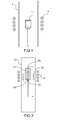
- the Applicant has developed a MERARG oven such as that illustrated in figure 1 for heating a metal crucible by inductive coupling.
- Induction coils 3 crossed by a high current Frequency can create currents induced in the metal crucible 1.
- these induced currents thus heat the walls of the crucible, which itself carries a sample at high temperature isothermally, the crucible being itself placed in a tube 2.
- induction heating can not be directly transcribed to the DURANCE device.
- susceptor corresponding to the part to be heated again called susceptor and in general, the susceptor must be an electrical conductor
- the zirconium alloy sheath metal element
- the sheath would be heated in the same way as the crucible in MERARG.
- first induction means that can be an induction coil for heating the central resistive system
- the solution proposed in the present invention adapts the principle of an electrical transformer.
- first induction means which can be a turn (coil) called transformation.
- This turn then creates a so-called induced current that flows in the resistance.
- This turn is placed inside the quartz tube and centered at the level of the induction coil.
- This device makes it possible to keep the same power supply system. It also makes it possible to preserve the quartz tube which guarantees the tightness of the oven and which, by its physico-chemical properties, does not interact with the coupling phenomenon.
- the figure 2 thus illustrates a device of the invention comprising in an enclosure 20, a resistor 60, a first induction coil 31 and a second so-called transformation turn 32.
- the sample to be heated 100 is surrounded by a not shown sheath and of an insulator 101 and is traversed by the resistor 60 at its center.
- a thermocouple 61 is also provided for the measurement of temperature.
- the device of the present invention thus makes it possible to heat inductively by coupling a metal element, and then by resistive heating of the resistor 60, to heat the inside of the pellets.
- This assembly makes it possible to keep the same power supply system. It allows also to keep for example a quartz tube that ensures the tightness of the oven and, by its physicochemical properties, does not interact on the coupling phenomenon.
- the DURANCE device seeks to apply a known and predetermined radial thermal gradient within an irradiated nuclear ceramic.
- the Applicant has modeled under Cast3m the thermal behavior of the device of the invention. This modeling allowed, as a first step, and through a parametric study as simple as possible, to confirm the presence of a radial gradient within the pellets and to specify the nature and the geometry of the insulators to obtain the gradient desired thermal.
- This analysis details the assumptions made to obtain a simplified model of DURANCE (definition of the geometric model, definition of the thermal model, ). The results obtained were confronted with the desired objectives to conclude on the validity of the concept.
- the cooling circuit is modeled by a temperature imposed at 20 ° C corresponding to the temperature of the water circulating in the exchanger as illustrated in figure 4 which shows, according to the thermal model, the injected power density P inj and the near-perfect conduction Cp between the different materials (pellet, sheath, insulator), between two adiabatic A dia .
- the modeling shows that in order to obtain a temperature at the outer wall of the sheath of 350 ° C., the insulator to be used is dense alumina with a thickness of 4 to 5 mm. .
- the thickness of this insulation is to be determined according to the temperatures at the center of the pellets.
- the choice of insulation is dense Hafnie between 3 and 5 mm thick depending on center temperatures pellets referred.
- the modeling shows the use of an insulator either in UO 2 or in Hafnie between 3 and 5 mm thickness depending the central temperature for a sheath temperature of 350 ° C.
- the assembly thus formed can be integrated into a quartz tube constituting an evolution of the MERARG II oven.
- the induction coil then couples on the turn of transformation, it is short-circuited by the tungsten resistance, passing through the wedges and fuel pellets.
- the turn of transformation, the induction coil and the exchanger are in turn cooled by water.
- thermocouple is mounted in contact with the resistor to observe its behavior during power up of the device.
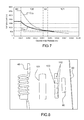
- the figure 9 illustrates, the temperature cycles applied at the level of the resistance. Three different ramps were applied and four trays in temperature (1000 ° C., 1300 ° C., 1600 ° C. and 2000 ° C.) were maintained between the ramps R 1 , R 2 and R 3 , the curve C 9 being relative to the temperature of the susceptor.
- the temperature of the resistor is voluntarily limited to a temperature of 2000 ° C over a very short time.
Abstract
Description
Le domaine de l'invention est celui des dispositifs de chauffage comportant la génération contrôlée de gradient thermique au sein d'un échantillon trouvant notamment un intérêt particulier pour contrôler et caractériser le comportement des combustibles nucléaires sous gradient thermique et qui soit utilisable en laboratoire de haute activité nucléaire.The field of the invention is that of heating devices comprising the controlled generation of thermal gradient within a sample, particularly finding a particular interest for controlling and characterizing the behavior of nuclear fuels under a thermal gradient and which can be used in a high-temperature laboratory. nuclear activity.
Dans ce domaine il a déjà été proposé par le Demandeur de produire un gradient thermique par un chauffage électrique à coeur des céramiques et une circulation d'eau à l'extérieur du gainage des céramiques. Néanmoins, ce dispositif n'a pas été utilisé sur combustibles nucléaires irradiés.In this field it has already been proposed by the Applicant to produce a thermal gradient by an electric heating core ceramic and a water circulation outside the cladding ceramics. Nevertheless, this device was not used on irradiated nuclear fuels.
Il est également connu du brevet
La publication
Actuellement, les quelques expériences de gradient thermique présentées, réalisées sur crayon combustible ont été menées sur des matériaux non irradiés en atmosphère inerte. Or les effets de l'irradiation impactent rapidement (en moins d'un cycle de réacteur à eau sous-pression : REP) les propriétés mécaniques et chimiques de la pastille et de la gaine ainsi que leur interface, modifiant de manière significative le comportement du combustible nucléaire.Currently, the few thermal gradient experiments presented, performed on fuel rod were conducted on non-irradiated materials in an inert atmosphere. However, the effects of irradiation rapidly impact (in less than one PWR PWR cycle) the mechanical and chemical properties of the pellet and sheath as well as their interface, significantly modifying the behavior of the reactor. nuclear fuel.
Or, dans le cadre des gestions de combustibles tels que le MOX à haute teneur en Plutonium avec un vecteur isotopique dégradé, le combustible MOX (pour « Mélanges d'Oxydes ») contenant du dioxyde de plutonium PuO2 et du dioxyde d'uranium UO2, fabriqué à partir d'environ 7 % de plutonium et 93 % d'uranium appauvri, la connaissance des phénomènes de transfert des produits de fission, notamment gazeux, au sein du combustible et des conditions de relâchement, nécessite d'être approfondie.However, in the context of the management of fuels such as MOX with a high content of Plutonium with a degraded isotopic vector, the MOX fuel (for "Oxide Mixes") containing plutonium dioxide PuO 2 and uranium dioxide UO 2 , made from about 7% plutonium and 93% depleted uranium, knowledge of the transfer phenomena of fission products, especially gaseous, within the fuel and loosening conditions, needs to be deepened.
Plus précisément, dans les réacteurs nucléaires actuels, exploités par EDF, les combustibles se présentent sous la forme de pastilles UO2 ou (U,Pu)O2 empilées dans une gaine en alliage de Zirconium. Lors de l'irradiation, il se produit notamment en raison de phénomènes thermomécaniques, une interaction entre les pastilles et la gaine (aussi appelée Interaction Pastille Gaine : IPG). Or, dans certaines conditions accidentelles de transitoires de puissance, le combustible peut subir un incrément important et rapide de température par rapport à sa situation normale. Ce transitoire thermique provoque une augmentation de la contrainte de la pastille sur la gaine et peut conduire à sa rupture. La gaine étant la première barrière de confinement aux produits de fission, il est indispensable de garantir son intégrité et donc de connaître au mieux ces phénomènes d'IPG.More precisely, in the current nuclear reactors operated by EDF, the fuels are in the form of UO 2 pellets or (U, Pu) O 2 stacked in a zirconium alloy sheath. During irradiation, it occurs in particular due to thermomechanical phenomena, an interaction between the pellets and the sheath (also called Interaction Pastille Sheath: IPG). However, under certain accident conditions of power transients, the fuel can undergo a large and rapid temperature increment compared to its normal situation. This thermal transient causes an increase in the stress of the pellet on the sheath and can lead to its rupture. As the sheath is the first containment barrier to fission products, it is essential to ensure its integrity and therefore to better understand these IPG phenomena.
Il est donc particulièrement intéressant de réaliser des expériences analytiques capables de simuler le gradient thermique subi par le combustible nucléaire lors de différentes « transitoires » de puissance et plus précisément de disposer d'un dispositif de caractérisation du comportement des combustibles nucléaires sous gradient thermique qui soit utilisable en laboratoire de haute activité. De telles expériences analytiques peuvent permettre de sélectionner des matériaux en vue d'obtenir un combustible dit remède ne conduisant pas à la rupture de la première barrière de confinement lors de certaines conditions accidentelles de transitoires de puissance.It is therefore particularly interesting to carry out analytical experiments capable of simulating the thermal gradient undergone by the nuclear fuel during different "transients" of power and more precisely to have a device for characterizing the behavior of nuclear fuel under thermal gradient that is usable in high activity laboratory. Such analytical experiments can make it possible to select materials in order to obtain a so-called remedial fuel that does not lead to the rupture of the first confinement barrier during certain accidental conditions of power transients.
Dans ce cadre, le Demandeur a développé un dispositif expérimental nommé DURANCE (Dispositif simUlant le compoRtement sous grAdieNt thermique des CombustiblEs). Ce dispositif DURANCE comporte un gradient thermique au sein de l'échantillon, assuré par un mandrin chauffant inséré à coeur et un système de matériaux isolants refroidis par un dispositif annexe. L'amplitude du gradient thermique entre le coeur de l'échantillon et la face externe de la gaine est, par conséquent, pilotée par le niveau de température à coeur et la nature, l'épaisseur et la température externe des isolants.In this context, the Applicant has developed an experimental device called DURANCE (Device simulating the composition under thermal combustion of the Combustibles). This DURANCE device comprises a thermal gradient within the sample, provided by a heating chuck inserted in the core and a system of insulating materials cooled by an auxiliary device. The amplitude of the thermal gradient between the core of the sample and the outer face of the sheath is, therefore, driven by the core temperature level and the nature, thickness and external temperature of the insulators.
Dans ce contexte, le Demandeur a cherché à mettre au point un dispositif permettant de reproduire et maîtriser l'amplitude du gradient thermique subi par le combustible nucléaire lors de certaines situations accidentelles et ce grâce à une installation de dimension réduite facilement adaptable aux fours de traitement thermiques utilisés par le laboratoire en cellule de haute activité et ce en s'affranchissant de toute circulation d'eau (pressurisée ou non) au contact de l'élément combustible, le chauffage étant assuré par induction. Le développement d'un système de chauffage par induction pour deux à trois pastilles de combustible assurant un flux thermique de l'intérieur vers l'extérieur de celles-ci permet de représenter le profil de température observé en réacteur. Il est destiné à permettre de faire progresser la problématique liée au risque de rupture de gaine par Interaction Pastille-Gaine / Corrosion sous Contrainte (IPG/CSC) des crayons combustibles en situation incidentelle, le nombre limité d'essais intégraux de rampe de puissance ne permettant pas de tester individuellement l'ensemble des paramètres et nuances de combustible ni d'accéder de façon découplée aux phénomènes physiques. Or certains mécanismes clés intervenant dans le phénomène d'interaction de la pastille avec la gaine sont encore mal connus et constituent un facteur limitant pour la compréhension des rampes et la représentativité des modèles numériques simulant l'IPG.In this context, the Applicant has sought to develop a device to reproduce and control the amplitude of the thermal gradient undergone by the nuclear fuel during certain accident situations and this thanks to a small-scale installation easily adaptable to the treatment furnaces thermal devices used by the laboratory in a high-activity cell and this by freeing itself from any water circulation (pressurized or not) in contact with the fuel element, the heating being provided by induction. The development of an induction heating system for two to three fuel pellets providing a heat flow from the inside to the outside of them makes it possible to represent the temperature profile observed in the reactor. It is intended to make it possible to advance the problem related to the risk of sheath failure by Paste-Sheath Interaction / Stress Corrosion (IPG / CSC) of the fuel rods in an incidental situation, the limited number of integral power ramp tests allowing not to individually test all the parameters and fuel grades nor to have a decoupled access to the physical phenomena. However, some key mechanisms involved in the interaction phenomenon of the pellet with the cladding are still poorly understood and constitute a limiting factor for the understanding of the ramps and the representativity of the numerical models simulating the IPG.
Un des objectifs important du dispositif proposé dans la présente invention est donc de reproduire et de maîtriser l'amplitude du gradient thermique subi par un combustible nucléaire lors de certaines situations accidentelles et ce grâce à une installation de dimension réduite facilement adaptable aux fours de traitement thermiques utilisés par un laboratoire en cellule de haute activité et ce en s'affranchissant de toute circulation d'eau (pressurisée ou non) au contact de l'élément combustible, le chauffage étant assuré par induction.One of the important objectives of the device proposed in the present invention is therefore to reproduce and control the amplitude of the thermal gradient undergone by a nuclear fuel during certain accident situations and this thanks to a reduced-size installation easily adaptable to heat treatment furnaces used by a laboratory in a high-activity cell and this by avoiding any circulation of water (pressurized or not) in contact with the fuel element, the heating being provided by induction.
Le dispositif de la présente invention constitue notamment une solution pouvant permettre de porter le combustible à une température centrale pouvant atteindre 2000°C, voire plus et stabiliser la température gaine aux alentours de 350°C +/- 50°C sur typiquement trois pastilles de combustible.The device of the present invention constitutes in particular a solution that can make it possible to bring the fuel to a central temperature of up to 2000 ° C., or even more, and stabilize the sheath temperature at around 350 ° C. +/- 50 ° C. on typically three pellets of combustible.
Plus précisément, la présente invention a pour objet un ensemble comprenant un échantillon et un dispositif pour générer un gradient élevé de température dans ledit échantillon caractérisé en ce qu'il comprend :
- une enceinte à l'intérieur de laquelle est placé ledit échantillon ;
- une résistante traversant ledit échantillon ;
- des premiers moyens d'induction en périphérie de l'enceinte pour créer un champ électromagnétique ;
- des seconds moyens d'induction connectés à ladite résistance et capables de capter ledit champ électromagnétique de manière à créer un courant induit circulant dans ladite résistance.
- an enclosure within which said sample is placed;
- a resistor passing through said sample;
- first inductive means at the periphery of the enclosure for creating an electromagnetic field;
- second inductive means connected to said resistor and capable of sensing said electromagnetic field so as to create an induced current flowing in said resistor.
Selon une variante de l'invention, les premiers moyens d'induction comprennent au moins une première bobine.According to a variant of the invention, the first induction means comprise at least a first coil.
Selon une variante de l'invention, les seconds moyens comprennent au moins une seconde bobine.According to a variant of the invention, the second means comprise at least one second coil.
Selon une variante de l'invention, l'enceinte est un tube de quartz.According to a variant of the invention, the enclosure is a quartz tube.
Selon une variante de l'invention, l'échantillon comprend une pastille de céramique pouvant être de Al2O3, ou du ZrO2 ou une pastille de combustible nucléaire pouvant être de l'UO2 ou du MOX.According to a variant of the invention, the sample comprises a ceramic pellet may be Al 2 O 3 , or ZrO 2 or a nuclear fuel pellet may be UO 2 or MOX.
Selon une variante de l'invention, l'échantillon comprend une gaine métallique en périphérie de ladite pastille et en contact direct avec ladite pastille.According to a variant of the invention, the sample comprises a metal sheath on the periphery of said wafer and in direct contact with said wafer.
Selon une variante de l'invention, il comprend en outre un élément isolant thermique en périphérie dudit échantillon.According to a variant of the invention, it further comprises a thermal insulating element at the periphery of said sample.
Selon une variante de l'invention, l'échantillon comprend une pastille de céramique, l'isolant étant en alumine.According to a variant of the invention, the sample comprises a ceramic pellet, the insulator being made of alumina.
Selon une variante de l'invention, l'échantillon comprend une pastille de céramique, l'isolant étant en hafnie.According to a variant of the invention, the sample comprises a ceramic pellet, the insulation being in hafnia.
Selon une variante de l'invention, l'échantillon comprend un combustible pouvant être en UO2, l'isolant pouvant être en UO2 ou en hafnie.According to a variant of the invention, the sample comprises a fuel that can be in UO 2 , the insulation can be in UO 2 or hafnia.
Selon une variante de l'invention, la résistance est en métal réfractaire pouvant être en tungstène ou en molybdène.According to a variant of the invention, the resistance is made of refractory metal that can be tungsten or molybdenum.
Selon une variante de l'invention, ledit ensemble comprend en outre un échangeur, lesdits seconds moyens d'induction étant situés en périphérie dudit échangeur.According to a variant of the invention, said assembly further comprises an exchanger, said second induction means being located at the periphery of said exchanger.
Selon une variante de l'invention, l'échangeur comprend un système de circulation de fluide.According to a variant of the invention, the exchanger comprises a fluid circulation system.
Selon une variante de l'invention, ledit ensemble comprend en outre des moyens de mesure de la température dudit échantillon.According to a variant of the invention, said assembly further comprises means for measuring the temperature of said sample.
Selon une variante de l'invention, les moyens de mesure de la température comprennent un thermocouple.According to a variant of the invention, the means for measuring the temperature comprise a thermocouple.
L'invention a aussi pour objet un ensemble selon l'invention comprenant un pyromètre.The invention also relates to an assembly according to the invention comprising a pyrometer.
L'invention a encore pour objet un ensemble selon l'invention comprenant une caméra infrarouge.The invention also relates to an assembly according to the invention comprising an infrared camera.
L'invention sera mieux comprise et d'autres avantages apparaîtront à la lecture de la description qui va suivre donnée à titre non limitatif et grâce aux figures annexées parmi lesquelles :
- la
figure 1 illustre un dispositif de chauffage ou four MERARG développé par le demandeur ; - la
figure 2 illustre un dispositif selon l'invention ; - les
figures 3a et 3b illustrent des modèles géométriques de l'ensemble : pastille de combustible entouré d'isolant, chauffé notamment par un mandrin métallique dans un dispositif de l'invention ; - la
figure 4 illustre le modèle thermique d'élément fini pour une pastille de combustible entourée d'isolant ; - la
figure 5 illustre l'évolution de la température en fonction de coordonnées radiales pour différents isolants et une pastille céramique d'Alumine ; - la
figure 6 illustre l'évolution de la température en fonction de coordonnées radiales pour différents isolants et une pastille céramique de Zircone ; - la
figure 7 illustre l'évolution de la température en fonction de coordonnées radiales pour différents isolants et une pastille céramique de UO2 ; - la
figure 8 illustre une vue éclatée de différents éléments compris dans un exemple de dispositif de l'invention ; - la
figure 9 illustre un exemple de cycle de températures appliquées au niveau de la résistance centrale dans un dispositif de l'invention.
- the
figure 1 illustrates a MERARG heating device or oven developed by the applicant; - the
figure 2 illustrates a device according to the invention; - the
Figures 3a and 3b illustrate geometric models of the assembly: fuel pellet surrounded by insulation, heated in particular by a metal mandrel in a device of the invention; - the
figure 4 illustrates the finite element thermal model for a fuel pellet surrounded by insulation; - the
figure 5 illustrates the evolution of the temperature as a function of radial coordinates for different insulators and a ceramic alumina pellet; - the
figure 6 illustrates the evolution of the temperature as a function of radial coordinates for different insulators and a zirconia ceramic pellet; - the
figure 7 illustrates the evolution of the temperature as a function of radial coordinates for different insulators and a UO 2 ceramic pellet; - the
figure 8 illustrates an exploded view of various elements included in an exemplary device of the invention; - the
figure 9 illustrates an example of a temperature cycle applied at the level of the central resistance in a device of the invention.
Le Demandeur a déveoppé un four MERARG tel que celui illustré en
Néanmoins, l'utilisation du chauffage par induction ne peut pas être directement transcrite au dispositif DURANCE. En effet, utiliser la résistance au centre des pastilles comme suscepteur (correspondant à la pièce à chauffer encore appelée suscepteur et de manière générale, le suscepteur doit être un conducteur électrique) vis-à-vis de l'induction n'est pas envisageable car la gaine en alliage de Zirconium (élément métallique), située entre le centre des pastilles et la spire, subirait le couplage. La gaine serait donc chauffée de la même façon que l'est le creuset dans MERARG.Nevertheless, the use of induction heating can not be directly transcribed to the DURANCE device. Indeed, to use the resistance in the center of the pellets as susceptor (corresponding to the part to be heated again called susceptor and in general, the susceptor must be an electrical conductor) vis-à-vis the induction is not possible because the zirconium alloy sheath (metal element), located between the center of the pellets and the coil, would undergo the coupling. The sheath would be heated in the same way as the crucible in MERARG.
Afin de pouvoir se servir du champ électromagnétique créé par des premiers moyens d'induction pouvant être une spire d'induction pour chauffer le système résistif central, la solution proposée dans la présente invention adapte le principe d'un transformateur électrique.In order to be able to use the electromagnetic field created by first induction means that can be an induction coil for heating the central resistive system, the solution proposed in the present invention adapts the principle of an electrical transformer.
Le champ électromagnétique est ainsi selon la présente invention, capté par des premiers moyens d'induction pouvant être une spire (bobine) dite de transformation. Cette spire crée alors un courant dit induit qui circule dans la résistance. Cette spire est placée à l'intérieur du tube de quartz et centrée au niveau de la spire d'induction.The electromagnetic field is thus according to the present invention, captured by first induction means which can be a turn (coil) called transformation. This turn then creates a so-called induced current that flows in the resistance. This turn is placed inside the quartz tube and centered at the level of the induction coil.
Ce dispositif permet bien de garder le même système d'apport de puissance. Il permet également de conserver le tube de quartz qui garantit l'étanchéité du four et qui, par ses propriétés physico-chimiques, n'interagit pas sur le phénomène de couplage.This device makes it possible to keep the same power supply system. It also makes it possible to preserve the quartz tube which guarantees the tightness of the oven and which, by its physico-chemical properties, does not interact with the coupling phenomenon.
La
Le dispositif de la présente invention permet ainsi de venir chauffer par couplage inductif un élément métallique, et ensuite par échauffement résistif de la résistance 60, de chauffer l'intérieur des pastilles. Ce montage permet bien de garder le même système d'apport de puissance. Il permet également de conserver par exemple un tube de quartz qui garantit l'étanchéité du four et qui, par ses propriétés physico-chimiques, n'interagit pas sur le phénomène de couplage.The device of the present invention thus makes it possible to heat inductively by coupling a metal element, and then by resistive heating of the
Pour que ce principe fournisse un chauffage plus homogène au sein de l'empilement des pastilles de combustible, on peut avantageusement doubler les spires de couplage et venir chauffer par induction deux éléments métalliques de part et d'autre.For this principle to provide a more homogeneous heating within the stack of fuel pellets, it is advantageous to double the coupling turns and come to heat by induction two metal elements on both sides.
De manière générale, le dispositif DURANCE cherche à appliquer un gradient thermique radial connu et prédéterminé au sein d'une céramique nucléaire irradiée. Afin de valider le concept envisagé, le Demandeur a modélisé sous Cast3m le comportement thermique du dispositif de l'invention. Cette modélisation a permis, dans un premier temps, et au travers d'une étude paramétrique la plus simple possible, de confirmer la présence d'un gradient radial au sein des pastilles et de spécifier la nature et la géométrie des isolants pour obtenir le gradient thermique souhaité. Cette analyse détaille les hypothèses posées pour obtenir un modèle simplifié de DURANCE (définition du modèle géométrique, définition du modèle thermique, ...). Les résultats obtenus ont été confrontés aux objectifs voulus pour conclure sur la validité du concept. Il a été décidé de modéliser le dispositif DURANCE de façon axisymétrique dans un premier temps sur un empilement de trois pastilles puis, pour simplifier encore le modèle, sur seulement la pastille centrale en négligeant les effets de bord des deux pastilles d'extrémités. Il est alors considéré qu'il n'y a pas d'échange thermique sur les faces inférieure et supérieure (condition adiabatique). Les
Le circuit de refroidissement est modélisé par une température imposée à 20°C correspondant à la température de l'eau circulant dans l'échangeur comme illustré en
Après avoir introduit dans les modèles considérés, les propriétés thermiques des matériaux étudiés, les calculs thermiques mettent en avant les résultats détaillés sur les
- la courbe C5A est relative à un isolant d'hafnie d'épaisseur de 3 mm, la courbe C5B est relative à un isolant d'alumine de 5 mm, pour un combustible Alumine ;
- la courbe C6A est relative à un isolant de zircone d'épaisseur de 3 mm, la courbe C6B est relative à un isolant d'alumine de 5 mm, pour un combustible Zircone ;
- la courbe C7A est relative à un isolant d'hafnie d'épaisseur de 3mm, la courbe C7B est relative à un isolant d'UO2 de 5 mm, pour un combustible d'UO2.
- the curve C 5A relates to a hafnite insulation of
thickness 3 mm, the curve C 5B relates to a 5 mm alumina insulation, for a fuel Alumina; - curve C 6A relates to a zirconia insulator with a thickness of 3 mm, curve C 6B relates to a 5 mm alumina insulation, for a zirconia fuel;
- Curve C 7A relates to a hafnite insulator with a thickness of 3 mm, curve C 7B is relative to a UO 2 insulation of 5 mm, for a UO 2 fuel.
Ces trois figures montrent directement qu'il est possible, en fonction du type d'échantillon (Al2O3, ZrO2 et UO2) faisant office de combustible, de proposer un système d'isolant permettant d'atteindre la température gaine voulue, quel que soit le chargement thermique à coeur.These three figures show directly that it is possible, depending on the type of sample (Al 2 O 3 , ZrO 2 and UO 2 ) serving as fuel, to propose an insulating system to achieve the desired sheath temperature. , regardless of the thermal loading at heart.
En effet, pour un simulant combustible de type alumine, la modélisation montre que pour obtenir une température à la paroi externe de la gaine de 350°C, l'isolant à utiliser est de l'alumine dense avec une épaisseur de 4 à 5 mm. L'épaisseur de cet isolant est à déterminer selon les températures au centre des pastilles. Pour un simulant combustible de type Zircone, le choix de l'isolant est de l'Hafnie dense entre 3 et 5 mm d'épaisseur selon les températures centre pastilles visées. Pour le combustible de type UO2 vierge, d'après les températures injectées à coeur de l'échantillon, la modélisation fait ressortir l'utilisation d'un isolant soit en UO2 soit en Hafnie entre 3 et 5 mm d'épaisseur en fonction de la température centrale et ce pour une température gaine de 350°C.Indeed, for an alumina-type fuel simulant, the modeling shows that in order to obtain a temperature at the outer wall of the sheath of 350 ° C., the insulator to be used is dense alumina with a thickness of 4 to 5 mm. . The thickness of this insulation is to be determined according to the temperatures at the center of the pellets. For a simulant fuel type Zirconia, the choice of insulation is dense Hafnie between 3 and 5 mm thick depending on center temperatures pellets referred. For virgin UO 2 type fuel, based on the temperatures injected at the core of the sample, the modeling shows the use of an insulator either in UO 2 or in Hafnie between 3 and 5 mm thickness depending the central temperature for a sheath temperature of 350 ° C.
A partir de cette modélisation thermique permettant de valider l'obtention d'un gradient thermique et un principe de chauffage a priori adéquat, le Demandeur a réalisé un prototype afin de vérifier le principe général et le bon fonctionnement, notamment le chauffage résistif et l'obtention d'un gradient thermique par le biais des différents isolants et de l'utilisation d'un système de refroidissement.From this thermal modeling to validate obtaining a thermal gradient and a heating principle a priori adequate, the Applicant has made a prototype to verify the general principle and the proper operation, including resistive heating and obtaining a thermal gradient through different insulators and the use of a cooling system.
Pour permettre la réalisation de ce prototype, les différents éléments ont été requis :
- une résistance permettant d'atteindre les températures souhaitées sans trop de déformations de celle-ci ;
- des pastilles percées simulant le combustible ;
- une gaine en zircaloy4 (zirconium) d'une hauteur de trois pastilles et des cales d'extrémités ;
- un jeu d'isolant ;
- deux spires, l'une de transformation pour permettre la circulation des courants induits dans la résistance, une spire d'induction ;
- un échangeur de chaleur afin de bloquer la température extérieure de l'isolant à la température de circulation de l'eau (soit 20 °C).
- resistance to achieve the desired temperatures without too much deformation thereof;
- pierced pellets simulating the fuel;
- a sheath zircaloy4 (zirconium) with a height of three pellets and wedges end;
- a set of insulation;
- two turns, one of transformation to allow the circulation of currents induced in the resistance, a turn of induction;
- a heat exchanger to block the outside temperature of the insulation at the circulating water temperature (
ie 20 ° C).
Ces éléments sont présentés sur la
L'ensemble ainsi constitué peut être intégré dans un tube en quartz constituant une évolution du four MERARG II. La spire d'induction couple alors sur la spire de transformation, celle-ci est court-circuitée par la résistance en tungstène, traversant les cales et les pastilles combustibles. La spire de transformation, la spire d'induction et l'échangeur sont quant à eux refroidis par eau.The assembly thus formed can be integrated into a quartz tube constituting an evolution of the MERARG II oven. The induction coil then couples on the turn of transformation, it is short-circuited by the tungsten resistance, passing through the wedges and fuel pellets. The turn of transformation, the induction coil and the exchanger are in turn cooled by water.
Un thermocouple est monté au contact de la résistance pour observer son comportement lors de la mise en puissance du dispositif.A thermocouple is mounted in contact with the resistor to observe its behavior during power up of the device.
La
Ces mesures valident le principe de chauffage proposé dans la présente invention, permettant des rampes de température plus ou moins rapides, avec des paliers de température dans les gammes requises.These measurements validate the heating principle proposed in the present invention, allowing more or less rapid temperature ramps, with temperature levels in the required ranges.
Claims (17)
Applications Claiming Priority (1)
| Application Number | Priority Date | Filing Date | Title |
|---|---|---|---|
| FR1253001A FR2988974B1 (en) | 2012-04-02 | 2012-04-02 | DEVICE FOR GENERATING A HIGH GRADIENT OF TEMPERATURE IN A NUCLEAR FUEL TYPE SAMPLE |
Publications (2)
| Publication Number | Publication Date |
|---|---|
| EP2648190A1 true EP2648190A1 (en) | 2013-10-09 |
| EP2648190B1 EP2648190B1 (en) | 2017-03-01 |
Family
ID=46754555
Family Applications (1)
| Application Number | Title | Priority Date | Filing Date |
|---|---|---|---|
| EP13161851.4A Not-in-force EP2648190B1 (en) | 2012-04-02 | 2013-03-29 | Device for generating a high temperature gradient in a nuclear fuel sample |
Country Status (7)
| Country | Link |
|---|---|
| US (1) | US20130259181A1 (en) |
| EP (1) | EP2648190B1 (en) |
| JP (1) | JP2013213821A (en) |
| KR (1) | KR20130112011A (en) |
| CN (1) | CN103366840A (en) |
| FR (1) | FR2988974B1 (en) |
| RU (1) | RU2013114461A (en) |
Families Citing this family (3)
| Publication number | Priority date | Publication date | Assignee | Title |
|---|---|---|---|---|
| FR2975527B1 (en) * | 2011-05-18 | 2013-07-05 | Commissariat Energie Atomique | DEVICE FOR ELECTRICALLY HEATING A LIQUID, ITS PRODUCTION METHOD AND APPLICATION TO THE ELECTRICAL SIMULATION OF NUCLEAR FUEL PENCILS |
| FR3011711B1 (en) * | 2013-10-03 | 2015-12-11 | Commissariat Energie Atomique | DEVICE FOR GENERATING A HIGH GRADIENT OF TEMPERATURE IN A NUCLEAR FUEL TYPE SAMPLE |
| JP6516659B2 (en) * | 2015-11-24 | 2019-05-22 | 三菱重工業株式会社 | Simulated pellet, simulated fuel rod, and simulated fuel assembly |
Citations (7)
| Publication number | Priority date | Publication date | Assignee | Title |
|---|---|---|---|---|
| JPS495689B1 (en) * | 1966-10-24 | 1974-02-08 | ||
| FR2582896A1 (en) * | 1985-06-04 | 1986-12-05 | Cableco Sa | Household electrical appliances or the like usable with induction ovens and not requiring to be plugged in for their supply |
| US4643866A (en) | 1983-08-24 | 1987-02-17 | The Babcock & Wilcox Company | Nuclear fuel pellet-cladding interaction test device and method modeling in-core reactor thermal conditions |
| US20060283849A1 (en) * | 2005-06-16 | 2006-12-21 | Ngk Spark Plug Co. Ltd. | Ceramic-metal assembly and ceramic heater |
| US20080023141A1 (en) * | 2006-07-26 | 2008-01-31 | Hitachi Kokusai Electric Inc. | Substrate processing apparatus |
| FR2931580A1 (en) * | 2008-05-21 | 2009-11-27 | Westinghouse Electric Corp | Elongated nuclear fuel rod integrity measuring method for nuclear reactor, involves determining temperature difference between points in plenum forming region, and comparing difference with standard to determine integrity of rod |
| US20110176650A1 (en) * | 2008-09-30 | 2011-07-21 | Areva Np | Nuclear reactor green and sintered fuel pellets, corresponding fuel rod and fuel assembly |
Family Cites Families (7)
| Publication number | Priority date | Publication date | Assignee | Title |
|---|---|---|---|---|
| NL234527A (en) * | 1958-12-22 | |||
| GB1136616A (en) * | 1965-12-01 | 1968-12-11 | Aeg Elotherm Gmbh | A method of and apparatus for inductively heating electrically conducting workpieces |
| BE744908A (en) * | 1969-02-01 | 1970-07-01 | Euratom | APPARATUS FOR THE STUDY OF THE EVOLUTION OF THE URANIUM FUEL STRUCTURE SUBJECT TO A RADIAL THERMAL GRADIENT |
| JPS57142525A (en) * | 1981-02-27 | 1982-09-03 | Toshiba Corp | Measuring method for output distribution of heater |
| JPS5957196A (en) * | 1982-09-28 | 1984-04-02 | 株式会社東芝 | Heat simulating specimen of nuclear fuel rod |
| FR2646049B1 (en) * | 1989-04-18 | 1991-05-24 | Cableco Sa | REMOVABLE ELECTRIC HEATER PLATE |
| US5084229A (en) * | 1990-05-31 | 1992-01-28 | The United States Of America As Represented By The United States Department Of Energy | Critical heat flux test apparatus |
-
2012
- 2012-04-02 FR FR1253001A patent/FR2988974B1/en active Active
-
2013
- 2013-03-29 EP EP13161851.4A patent/EP2648190B1/en not_active Not-in-force
- 2013-04-01 RU RU2013114461/07A patent/RU2013114461A/en not_active Application Discontinuation
- 2013-04-02 CN CN2013101658273A patent/CN103366840A/en active Pending
- 2013-04-02 US US13/855,615 patent/US20130259181A1/en not_active Abandoned
- 2013-04-02 JP JP2013076952A patent/JP2013213821A/en active Pending
- 2013-04-02 KR KR1020130036001A patent/KR20130112011A/en not_active Application Discontinuation
Patent Citations (7)
| Publication number | Priority date | Publication date | Assignee | Title |
|---|---|---|---|---|
| JPS495689B1 (en) * | 1966-10-24 | 1974-02-08 | ||
| US4643866A (en) | 1983-08-24 | 1987-02-17 | The Babcock & Wilcox Company | Nuclear fuel pellet-cladding interaction test device and method modeling in-core reactor thermal conditions |
| FR2582896A1 (en) * | 1985-06-04 | 1986-12-05 | Cableco Sa | Household electrical appliances or the like usable with induction ovens and not requiring to be plugged in for their supply |
| US20060283849A1 (en) * | 2005-06-16 | 2006-12-21 | Ngk Spark Plug Co. Ltd. | Ceramic-metal assembly and ceramic heater |
| US20080023141A1 (en) * | 2006-07-26 | 2008-01-31 | Hitachi Kokusai Electric Inc. | Substrate processing apparatus |
| FR2931580A1 (en) * | 2008-05-21 | 2009-11-27 | Westinghouse Electric Corp | Elongated nuclear fuel rod integrity measuring method for nuclear reactor, involves determining temperature difference between points in plenum forming region, and comparing difference with standard to determine integrity of rod |
| US20110176650A1 (en) * | 2008-09-30 | 2011-07-21 | Areva Np | Nuclear reactor green and sintered fuel pellets, corresponding fuel rod and fuel assembly |
Non-Patent Citations (1)
| Title |
|---|
| J.F. WHATHAM, NUCLEAR ENGINEERING AND DESIGN, vol. 26, 1974, pages 423 - 431 |
Also Published As
| Publication number | Publication date |
|---|---|
| RU2013114461A (en) | 2014-10-10 |
| KR20130112011A (en) | 2013-10-11 |
| FR2988974B1 (en) | 2017-09-01 |
| JP2013213821A (en) | 2013-10-17 |
| FR2988974A1 (en) | 2013-10-04 |
| US20130259181A1 (en) | 2013-10-03 |
| CN103366840A (en) | 2013-10-23 |
| EP2648190B1 (en) | 2017-03-01 |
Similar Documents
| Publication | Publication Date | Title |
|---|---|---|
| EP2648190B1 (en) | Device for generating a high temperature gradient in a nuclear fuel sample | |
| Seo et al. | Pool boiling heat transfer characteristics of zircaloy and SiC claddings in deionized water at low pressure | |
| EP2858072B1 (en) | Device for generating a high temperature gradient in a sample, including optical control means | |
| Bianco et al. | Experimental investigation on the causes for pellet fragmentation under LOCA conditions | |
| Su et al. | Wettability and CHF limits of Accident-Tolerant nuclear fuel cladding materials in light water reactor conditions | |
| Kossolapov | Transient flow boiling CHF under exponentially escalating heat inputs | |
| Seong et al. | Separate effect of oxidation on the subcooled flow boiling performance of Zircaloy-4 at atmospheric pressure | |
| Kamerman et al. | Transient testing of uranium silicide fuel in zircaloy and silicon carbide cladding | |
| Shibata et al. | Control blade degradation test under temperature gradient in steam atmosphere | |
| Spencer et al. | Separate-effects validation experiments for models of fracture in ceramic nuclear fuel | |
| Ortega et al. | Thermal-shock experiments for separate-effects validation of UO2 fuel fracture models | |
| Ueta et al. | R&D plan for development of oxidation-resistant graphite and investigation of oxidation behavior of SiC coated fuel particle to enhance safety of HTGR | |
| Fudurich | Effect of liquid subcooling, initial surface temperature, and surface properties on the minimum film boiling temperature | |
| Laurie et al. | New temperature monitoring devices for high-temperature irradiation experiments in the High Flux Reactor Petten | |
| Kato et al. | Hydrogen diffusivity in oxide layers formed in Zr alloy in air or steam | |
| Zeng et al. | A scoping study on remelting process of a debris bed in the lower head of reactor pressure vessel | |
| Ferry et al. | The LORELEI test device for LOCA experiments in the Jules Horowitz reactor | |
| Singh et al. | Effects of elevated temperature steam oxidation and subsequent quenching on light water reactor clad | |
| Doyle et al. | Analysis of iron-chromium-aluminum samples exposed to accident conditions followed by quench in the QUENCH-19 experiment | |
| Scholte et al. | Design and GLADIS testing of a liquid tin divertor module prior to exposure in ASDEX Upgrade | |
| Wang | Experimental investigation of critical heat flux enhancement on engineered surfaces with infrared thermometry | |
| Condie et al. | Design and evaluation of an enhanced in-vessel core catcher | |
| Kruglov et al. | Thermal contact resistance of a liquid lead and structural steel | |
| Grachev et al. | Features of Radiation Swelling of Uranium-Plutonium Nitride Fuel in Experimental Fuel Rods with Helium and Lead Sublayer | |
| Rempe | In-vessel retention-recent efforts and future needs |
Legal Events
| Date | Code | Title | Description |
|---|---|---|---|
| PUAI | Public reference made under article 153(3) epc to a published international application that has entered the european phase |
Free format text: ORIGINAL CODE: 0009012 |
|
| AK | Designated contracting states |
Kind code of ref document: A1 Designated state(s): AL AT BE BG CH CY CZ DE DK EE ES FI FR GB GR HR HU IE IS IT LI LT LU LV MC MK MT NL NO PL PT RO RS SE SI SK SM TR |
|
| AX | Request for extension of the european patent |
Extension state: BA ME |
|
| 17P | Request for examination filed |
Effective date: 20140312 |
|
| RBV | Designated contracting states (corrected) |
Designated state(s): AL AT BE BG CH CY CZ DE DK EE ES FI FR GB GR HR HU IE IS IT LI LT LU LV MC MK MT NL NO PL PT RO RS SE SI SK SM TR |
|
| GRAP | Despatch of communication of intention to grant a patent |
Free format text: ORIGINAL CODE: EPIDOSNIGR1 |
|
| INTG | Intention to grant announced |
Effective date: 20160929 |
|
| GRAS | Grant fee paid |
Free format text: ORIGINAL CODE: EPIDOSNIGR3 |
|
| GRAA | (expected) grant |
Free format text: ORIGINAL CODE: 0009210 |
|
| AK | Designated contracting states |
Kind code of ref document: B1 Designated state(s): AL AT BE BG CH CY CZ DE DK EE ES FI FR GB GR HR HU IE IS IT LI LT LU LV MC MK MT NL NO PL PT RO RS SE SI SK SM TR |
|
| REG | Reference to a national code |
Ref country code: GB Ref legal event code: FG4D Free format text: NOT ENGLISH |
|
| REG | Reference to a national code |
Ref country code: CH Ref legal event code: EP Ref country code: AT Ref legal event code: REF Ref document number: 872181 Country of ref document: AT Kind code of ref document: T Effective date: 20170315 |
|
| REG | Reference to a national code |
Ref country code: IE Ref legal event code: FG4D Free format text: LANGUAGE OF EP DOCUMENT: FRENCH |
|
| REG | Reference to a national code |
Ref country code: FR Ref legal event code: PLFP Year of fee payment: 5 |
|
| REG | Reference to a national code |
Ref country code: DE Ref legal event code: R096 Ref document number: 602013017849 Country of ref document: DE |
|
| REG | Reference to a national code |
Ref country code: SE Ref legal event code: TRGR |
|
| REG | Reference to a national code |
Ref country code: NL Ref legal event code: MP Effective date: 20170301 |
|
| REG | Reference to a national code |
Ref country code: LT Ref legal event code: MG4D |
|
| REG | Reference to a national code |
Ref country code: AT Ref legal event code: MK05 Ref document number: 872181 Country of ref document: AT Kind code of ref document: T Effective date: 20170301 |
|
| PG25 | Lapsed in a contracting state [announced via postgrant information from national office to epo] |
Ref country code: NO Free format text: LAPSE BECAUSE OF FAILURE TO SUBMIT A TRANSLATION OF THE DESCRIPTION OR TO PAY THE FEE WITHIN THE PRESCRIBED TIME-LIMIT Effective date: 20170601 Ref country code: LT Free format text: LAPSE BECAUSE OF FAILURE TO SUBMIT A TRANSLATION OF THE DESCRIPTION OR TO PAY THE FEE WITHIN THE PRESCRIBED TIME-LIMIT Effective date: 20170301 Ref country code: HR Free format text: LAPSE BECAUSE OF FAILURE TO SUBMIT A TRANSLATION OF THE DESCRIPTION OR TO PAY THE FEE WITHIN THE PRESCRIBED TIME-LIMIT Effective date: 20170301 Ref country code: FI Free format text: LAPSE BECAUSE OF FAILURE TO SUBMIT A TRANSLATION OF THE DESCRIPTION OR TO PAY THE FEE WITHIN THE PRESCRIBED TIME-LIMIT Effective date: 20170301 |
|
| PG25 | Lapsed in a contracting state [announced via postgrant information from national office to epo] |
Ref country code: LV Free format text: LAPSE BECAUSE OF FAILURE TO SUBMIT A TRANSLATION OF THE DESCRIPTION OR TO PAY THE FEE WITHIN THE PRESCRIBED TIME-LIMIT Effective date: 20170301 Ref country code: RS Free format text: LAPSE BECAUSE OF FAILURE TO SUBMIT A TRANSLATION OF THE DESCRIPTION OR TO PAY THE FEE WITHIN THE PRESCRIBED TIME-LIMIT Effective date: 20170301 Ref country code: BG Free format text: LAPSE BECAUSE OF FAILURE TO SUBMIT A TRANSLATION OF THE DESCRIPTION OR TO PAY THE FEE WITHIN THE PRESCRIBED TIME-LIMIT Effective date: 20170601 Ref country code: ES Free format text: LAPSE BECAUSE OF FAILURE TO SUBMIT A TRANSLATION OF THE DESCRIPTION OR TO PAY THE FEE WITHIN THE PRESCRIBED TIME-LIMIT Effective date: 20170301 Ref country code: AT Free format text: LAPSE BECAUSE OF FAILURE TO SUBMIT A TRANSLATION OF THE DESCRIPTION OR TO PAY THE FEE WITHIN THE PRESCRIBED TIME-LIMIT Effective date: 20170301 |
|
| PG25 | Lapsed in a contracting state [announced via postgrant information from national office to epo] |
Ref country code: NL Free format text: LAPSE BECAUSE OF FAILURE TO SUBMIT A TRANSLATION OF THE DESCRIPTION OR TO PAY THE FEE WITHIN THE PRESCRIBED TIME-LIMIT Effective date: 20170301 |
|
| PG25 | Lapsed in a contracting state [announced via postgrant information from national office to epo] |
Ref country code: SK Free format text: LAPSE BECAUSE OF FAILURE TO SUBMIT A TRANSLATION OF THE DESCRIPTION OR TO PAY THE FEE WITHIN THE PRESCRIBED TIME-LIMIT Effective date: 20170301 Ref country code: CZ Free format text: LAPSE BECAUSE OF FAILURE TO SUBMIT A TRANSLATION OF THE DESCRIPTION OR TO PAY THE FEE WITHIN THE PRESCRIBED TIME-LIMIT Effective date: 20170301 Ref country code: IT Free format text: LAPSE BECAUSE OF FAILURE TO SUBMIT A TRANSLATION OF THE DESCRIPTION OR TO PAY THE FEE WITHIN THE PRESCRIBED TIME-LIMIT Effective date: 20170301 Ref country code: EE Free format text: LAPSE BECAUSE OF FAILURE TO SUBMIT A TRANSLATION OF THE DESCRIPTION OR TO PAY THE FEE WITHIN THE PRESCRIBED TIME-LIMIT Effective date: 20170301 Ref country code: RO Free format text: LAPSE BECAUSE OF FAILURE TO SUBMIT A TRANSLATION OF THE DESCRIPTION OR TO PAY THE FEE WITHIN THE PRESCRIBED TIME-LIMIT Effective date: 20170301 |
|
| REG | Reference to a national code |
Ref country code: CH Ref legal event code: PL |
|
| PG25 | Lapsed in a contracting state [announced via postgrant information from national office to epo] |
Ref country code: SM Free format text: LAPSE BECAUSE OF FAILURE TO SUBMIT A TRANSLATION OF THE DESCRIPTION OR TO PAY THE FEE WITHIN THE PRESCRIBED TIME-LIMIT Effective date: 20170301 Ref country code: PT Free format text: LAPSE BECAUSE OF FAILURE TO SUBMIT A TRANSLATION OF THE DESCRIPTION OR TO PAY THE FEE WITHIN THE PRESCRIBED TIME-LIMIT Effective date: 20170703 Ref country code: IS Free format text: LAPSE BECAUSE OF FAILURE TO SUBMIT A TRANSLATION OF THE DESCRIPTION OR TO PAY THE FEE WITHIN THE PRESCRIBED TIME-LIMIT Effective date: 20170701 Ref country code: PL Free format text: LAPSE BECAUSE OF FAILURE TO SUBMIT A TRANSLATION OF THE DESCRIPTION OR TO PAY THE FEE WITHIN THE PRESCRIBED TIME-LIMIT Effective date: 20170301 |
|
| REG | Reference to a national code |
Ref country code: DE Ref legal event code: R097 Ref document number: 602013017849 Country of ref document: DE |
|
| REG | Reference to a national code |
Ref country code: IE Ref legal event code: MM4A |
|
| PLBE | No opposition filed within time limit |
Free format text: ORIGINAL CODE: 0009261 |
|
| STAA | Information on the status of an ep patent application or granted ep patent |
Free format text: STATUS: NO OPPOSITION FILED WITHIN TIME LIMIT |
|
| PG25 | Lapsed in a contracting state [announced via postgrant information from national office to epo] |
Ref country code: MC Free format text: LAPSE BECAUSE OF FAILURE TO SUBMIT A TRANSLATION OF THE DESCRIPTION OR TO PAY THE FEE WITHIN THE PRESCRIBED TIME-LIMIT Effective date: 20170301 Ref country code: DK Free format text: LAPSE BECAUSE OF FAILURE TO SUBMIT A TRANSLATION OF THE DESCRIPTION OR TO PAY THE FEE WITHIN THE PRESCRIBED TIME-LIMIT Effective date: 20170301 Ref country code: LU Free format text: LAPSE BECAUSE OF NON-PAYMENT OF DUE FEES Effective date: 20170329 |
|
| 26N | No opposition filed |
Effective date: 20171204 |
|
| PG25 | Lapsed in a contracting state [announced via postgrant information from national office to epo] |
Ref country code: SI Free format text: LAPSE BECAUSE OF FAILURE TO SUBMIT A TRANSLATION OF THE DESCRIPTION OR TO PAY THE FEE WITHIN THE PRESCRIBED TIME-LIMIT Effective date: 20170301 Ref country code: IE Free format text: LAPSE BECAUSE OF NON-PAYMENT OF DUE FEES Effective date: 20170329 Ref country code: CH Free format text: LAPSE BECAUSE OF NON-PAYMENT OF DUE FEES Effective date: 20170331 Ref country code: LI Free format text: LAPSE BECAUSE OF NON-PAYMENT OF DUE FEES Effective date: 20170331 |
|
| REG | Reference to a national code |
Ref country code: FR Ref legal event code: PLFP Year of fee payment: 6 |
|
| PG25 | Lapsed in a contracting state [announced via postgrant information from national office to epo] |
Ref country code: MT Free format text: LAPSE BECAUSE OF FAILURE TO SUBMIT A TRANSLATION OF THE DESCRIPTION OR TO PAY THE FEE WITHIN THE PRESCRIBED TIME-LIMIT Effective date: 20170301 |
|
| PG25 | Lapsed in a contracting state [announced via postgrant information from national office to epo] |
Ref country code: HU Free format text: LAPSE BECAUSE OF FAILURE TO SUBMIT A TRANSLATION OF THE DESCRIPTION OR TO PAY THE FEE WITHIN THE PRESCRIBED TIME-LIMIT; INVALID AB INITIO Effective date: 20130329 |
|
| PG25 | Lapsed in a contracting state [announced via postgrant information from national office to epo] |
Ref country code: CY Free format text: LAPSE BECAUSE OF NON-PAYMENT OF DUE FEES Effective date: 20170301 |
|
| PG25 | Lapsed in a contracting state [announced via postgrant information from national office to epo] |
Ref country code: MK Free format text: LAPSE BECAUSE OF FAILURE TO SUBMIT A TRANSLATION OF THE DESCRIPTION OR TO PAY THE FEE WITHIN THE PRESCRIBED TIME-LIMIT Effective date: 20170301 |
|
| PG25 | Lapsed in a contracting state [announced via postgrant information from national office to epo] |
Ref country code: TR Free format text: LAPSE BECAUSE OF FAILURE TO SUBMIT A TRANSLATION OF THE DESCRIPTION OR TO PAY THE FEE WITHIN THE PRESCRIBED TIME-LIMIT Effective date: 20170301 |
|
| PGFP | Annual fee paid to national office [announced via postgrant information from national office to epo] |
Ref country code: SE Payment date: 20200327 Year of fee payment: 8 Ref country code: GB Payment date: 20200323 Year of fee payment: 8 Ref country code: DE Payment date: 20200311 Year of fee payment: 8 |
|
| PGFP | Annual fee paid to national office [announced via postgrant information from national office to epo] |
Ref country code: BE Payment date: 20200330 Year of fee payment: 8 |
|
| PG25 | Lapsed in a contracting state [announced via postgrant information from national office to epo] |
Ref country code: GR Free format text: LAPSE BECAUSE OF FAILURE TO SUBMIT A TRANSLATION OF THE DESCRIPTION OR TO PAY THE FEE WITHIN THE PRESCRIBED TIME-LIMIT Effective date: 20170301 |
|
| PG25 | Lapsed in a contracting state [announced via postgrant information from national office to epo] |
Ref country code: AL Free format text: LAPSE BECAUSE OF FAILURE TO SUBMIT A TRANSLATION OF THE DESCRIPTION OR TO PAY THE FEE WITHIN THE PRESCRIBED TIME-LIMIT Effective date: 20170301 |
|
| PGFP | Annual fee paid to national office [announced via postgrant information from national office to epo] |
Ref country code: FR Payment date: 20200331 Year of fee payment: 8 |
|
| REG | Reference to a national code |
Ref country code: DE Ref legal event code: R119 Ref document number: 602013017849 Country of ref document: DE |
|
| GBPC | Gb: european patent ceased through non-payment of renewal fee |
Effective date: 20210329 |
|
| REG | Reference to a national code |
Ref country code: BE Ref legal event code: MM Effective date: 20210331 |
|
| PG25 | Lapsed in a contracting state [announced via postgrant information from national office to epo] |
Ref country code: FR Free format text: LAPSE BECAUSE OF NON-PAYMENT OF DUE FEES Effective date: 20210331 Ref country code: GB Free format text: LAPSE BECAUSE OF NON-PAYMENT OF DUE FEES Effective date: 20210329 Ref country code: DE Free format text: LAPSE BECAUSE OF NON-PAYMENT OF DUE FEES Effective date: 20211001 Ref country code: SE Free format text: LAPSE BECAUSE OF NON-PAYMENT OF DUE FEES Effective date: 20210330 |
|
| PG25 | Lapsed in a contracting state [announced via postgrant information from national office to epo] |
Ref country code: BE Free format text: LAPSE BECAUSE OF NON-PAYMENT OF DUE FEES Effective date: 20210331 |