EP2648031A1 - Pilote de lentille pour lentille ophtalmique électronique optique variable - Google Patents
Pilote de lentille pour lentille ophtalmique électronique optique variable Download PDFInfo
- Publication number
- EP2648031A1 EP2648031A1 EP13162192.2A EP13162192A EP2648031A1 EP 2648031 A1 EP2648031 A1 EP 2648031A1 EP 13162192 A EP13162192 A EP 13162192A EP 2648031 A1 EP2648031 A1 EP 2648031A1
- Authority
- EP
- European Patent Office
- Prior art keywords
- lens
- variable
- ophthalmic apparatus
- ophthalmic
- optic element
- Prior art date
- Legal status (The legal status is an assumption and is not a legal conclusion. Google has not performed a legal analysis and makes no representation as to the accuracy of the status listed.)
- Granted
Links
- 239000007788 liquid Substances 0.000 claims description 27
- 230000004438 eyesight Effects 0.000 claims description 25
- 230000005499 meniscus Effects 0.000 claims description 12
- 229920000642 polymer Polymers 0.000 claims description 9
- 238000012937 correction Methods 0.000 claims description 7
- 238000010348 incorporation Methods 0.000 claims description 6
- 239000004033 plastic Substances 0.000 claims description 6
- 238000002955 isolation Methods 0.000 claims description 3
- 210000000695 crystalline len Anatomy 0.000 description 297
- 239000003990 capacitor Substances 0.000 description 36
- 238000013461 design Methods 0.000 description 19
- 230000006870 function Effects 0.000 description 17
- 230000008859 change Effects 0.000 description 13
- 238000000034 method Methods 0.000 description 13
- 230000003287 optical effect Effects 0.000 description 13
- 238000005516 engineering process Methods 0.000 description 10
- 230000004913 activation Effects 0.000 description 9
- 238000007726 management method Methods 0.000 description 9
- 230000004044 response Effects 0.000 description 9
- 239000008280 blood Substances 0.000 description 8
- 210000004369 blood Anatomy 0.000 description 8
- 230000009471 action Effects 0.000 description 7
- 238000004519 manufacturing process Methods 0.000 description 7
- FAPWRFPIFSIZLT-UHFFFAOYSA-M Sodium chloride Chemical compound [Na+].[Cl-] FAPWRFPIFSIZLT-UHFFFAOYSA-M 0.000 description 6
- 230000001276 controlling effect Effects 0.000 description 6
- 238000012544 monitoring process Methods 0.000 description 6
- 230000007547 defect Effects 0.000 description 5
- 239000012530 fluid Substances 0.000 description 5
- 230000002441 reversible effect Effects 0.000 description 5
- 239000004065 semiconductor Substances 0.000 description 5
- 239000011780 sodium chloride Substances 0.000 description 5
- 230000008901 benefit Effects 0.000 description 4
- 239000000090 biomarker Substances 0.000 description 4
- HVYWMOMLDIMFJA-DPAQBDIFSA-N cholesterol Chemical compound C1C=C2C[C@@H](O)CC[C@]2(C)[C@@H]2[C@@H]1[C@@H]1CC[C@H]([C@H](C)CCCC(C)C)[C@@]1(C)CC2 HVYWMOMLDIMFJA-DPAQBDIFSA-N 0.000 description 4
- 230000000295 complement effect Effects 0.000 description 4
- 230000003750 conditioning effect Effects 0.000 description 4
- 239000004973 liquid crystal related substance Substances 0.000 description 4
- 230000008569 process Effects 0.000 description 4
- DGAQECJNVWCQMB-PUAWFVPOSA-M Ilexoside XXIX Chemical compound C[C@@H]1CC[C@@]2(CC[C@@]3(C(=CC[C@H]4[C@]3(CC[C@@H]5[C@@]4(CC[C@@H](C5(C)C)OS(=O)(=O)[O-])C)C)[C@@H]2[C@]1(C)O)C)C(=O)O[C@H]6[C@@H]([C@H]([C@@H]([C@H](O6)CO)O)O)O.[Na+] DGAQECJNVWCQMB-PUAWFVPOSA-M 0.000 description 3
- ZLMJMSJWJFRBEC-UHFFFAOYSA-N Potassium Chemical compound [K] ZLMJMSJWJFRBEC-UHFFFAOYSA-N 0.000 description 3
- 238000004891 communication Methods 0.000 description 3
- 238000010586 diagram Methods 0.000 description 3
- 239000010408 film Substances 0.000 description 3
- 238000007667 floating Methods 0.000 description 3
- 208000001491 myopia Diseases 0.000 description 3
- 230000004379 myopia Effects 0.000 description 3
- 239000003921 oil Substances 0.000 description 3
- 239000011591 potassium Substances 0.000 description 3
- 229910052700 potassium Inorganic materials 0.000 description 3
- 210000001525 retina Anatomy 0.000 description 3
- 238000004088 simulation Methods 0.000 description 3
- 239000011734 sodium Substances 0.000 description 3
- 229910052708 sodium Inorganic materials 0.000 description 3
- 230000015556 catabolic process Effects 0.000 description 2
- 238000006243 chemical reaction Methods 0.000 description 2
- 235000012000 cholesterol Nutrition 0.000 description 2
- 238000010276 construction Methods 0.000 description 2
- 206010012601 diabetes mellitus Diseases 0.000 description 2
- 239000003814 drug Substances 0.000 description 2
- 230000005669 field effect Effects 0.000 description 2
- 230000036541 health Effects 0.000 description 2
- 230000006872 improvement Effects 0.000 description 2
- 230000010354 integration Effects 0.000 description 2
- 230000007774 longterm Effects 0.000 description 2
- 238000005457 optimization Methods 0.000 description 2
- 230000005693 optoelectronics Effects 0.000 description 2
- 230000002093 peripheral effect Effects 0.000 description 2
- 238000012545 processing Methods 0.000 description 2
- 230000009467 reduction Effects 0.000 description 2
- 230000003068 static effect Effects 0.000 description 2
- 238000003860 storage Methods 0.000 description 2
- 239000000126 substance Substances 0.000 description 2
- 239000000758 substrate Substances 0.000 description 2
- 230000000007 visual effect Effects 0.000 description 2
- 239000002699 waste material Substances 0.000 description 2
- XLYOFNOQVPJJNP-UHFFFAOYSA-N water Substances O XLYOFNOQVPJJNP-UHFFFAOYSA-N 0.000 description 2
- OYPRJOBELJOOCE-UHFFFAOYSA-N Calcium Chemical compound [Ca] OYPRJOBELJOOCE-UHFFFAOYSA-N 0.000 description 1
- 208000002177 Cataract Diseases 0.000 description 1
- RYGMFSIKBFXOCR-UHFFFAOYSA-N Copper Chemical compound [Cu] RYGMFSIKBFXOCR-UHFFFAOYSA-N 0.000 description 1
- 208000003556 Dry Eye Syndromes Diseases 0.000 description 1
- 206010013774 Dry eye Diseases 0.000 description 1
- 239000004593 Epoxy Substances 0.000 description 1
- WQZGKKKJIJFFOK-GASJEMHNSA-N Glucose Natural products OC[C@H]1OC(O)[C@H](O)[C@@H](O)[C@@H]1O WQZGKKKJIJFFOK-GASJEMHNSA-N 0.000 description 1
- 206010020675 Hypermetropia Diseases 0.000 description 1
- 241001124569 Lycaenidae Species 0.000 description 1
- FYYHWMGAXLPEAU-UHFFFAOYSA-N Magnesium Chemical compound [Mg] FYYHWMGAXLPEAU-UHFFFAOYSA-N 0.000 description 1
- 239000004642 Polyimide Substances 0.000 description 1
- 241000083513 Punctum Species 0.000 description 1
- XUIMIQQOPSSXEZ-UHFFFAOYSA-N Silicon Chemical compound [Si] XUIMIQQOPSSXEZ-UHFFFAOYSA-N 0.000 description 1
- 230000004308 accommodation Effects 0.000 description 1
- 230000003213 activating effect Effects 0.000 description 1
- 239000007864 aqueous solution Substances 0.000 description 1
- 201000009310 astigmatism Diseases 0.000 description 1
- 230000003190 augmentative effect Effects 0.000 description 1
- 210000004556 brain Anatomy 0.000 description 1
- 239000011575 calcium Substances 0.000 description 1
- 229910052791 calcium Inorganic materials 0.000 description 1
- 150000003841 chloride salts Chemical class 0.000 description 1
- 230000001684 chronic effect Effects 0.000 description 1
- 239000003086 colorant Substances 0.000 description 1
- 229910052802 copper Inorganic materials 0.000 description 1
- 239000010949 copper Substances 0.000 description 1
- 210000004087 cornea Anatomy 0.000 description 1
- 230000008878 coupling Effects 0.000 description 1
- 238000010168 coupling process Methods 0.000 description 1
- 238000005859 coupling reaction Methods 0.000 description 1
- 239000003989 dielectric material Substances 0.000 description 1
- 201000010099 disease Diseases 0.000 description 1
- 208000037265 diseases, disorders, signs and symptoms Diseases 0.000 description 1
- 229940079593 drug Drugs 0.000 description 1
- 230000000694 effects Effects 0.000 description 1
- 239000003792 electrolyte Substances 0.000 description 1
- 239000008103 glucose Substances 0.000 description 1
- MSNOMDLPLDYDME-UHFFFAOYSA-N gold nickel Chemical compound [Ni].[Au] MSNOMDLPLDYDME-UHFFFAOYSA-N 0.000 description 1
- 230000005484 gravity Effects 0.000 description 1
- 230000002209 hydrophobic effect Effects 0.000 description 1
- 201000006318 hyperopia Diseases 0.000 description 1
- 230000004305 hyperopia Effects 0.000 description 1
- 239000007943 implant Substances 0.000 description 1
- 230000001939 inductive effect Effects 0.000 description 1
- 238000001802 infusion Methods 0.000 description 1
- 238000003780 insertion Methods 0.000 description 1
- 230000037431 insertion Effects 0.000 description 1
- 238000011545 laboratory measurement Methods 0.000 description 1
- 239000011777 magnesium Substances 0.000 description 1
- 229910052749 magnesium Inorganic materials 0.000 description 1
- 238000005259 measurement Methods 0.000 description 1
- 230000007246 mechanism Effects 0.000 description 1
- 238000002483 medication Methods 0.000 description 1
- 229910044991 metal oxide Inorganic materials 0.000 description 1
- 150000004706 metal oxides Chemical class 0.000 description 1
- 238000004377 microelectronic Methods 0.000 description 1
- 238000012986 modification Methods 0.000 description 1
- 230000004048 modification Effects 0.000 description 1
- 210000000056 organ Anatomy 0.000 description 1
- 238000004806 packaging method and process Methods 0.000 description 1
- 230000000737 periodic effect Effects 0.000 description 1
- 229920001721 polyimide Polymers 0.000 description 1
- 238000012805 post-processing Methods 0.000 description 1
- 238000005381 potential energy Methods 0.000 description 1
- 201000010041 presbyopia Diseases 0.000 description 1
- 208000014733 refractive error Diseases 0.000 description 1
- 230000001105 regulatory effect Effects 0.000 description 1
- 229910052710 silicon Inorganic materials 0.000 description 1
- 239000010703 silicon Substances 0.000 description 1
- 239000007787 solid Substances 0.000 description 1
- 239000000243 solution Substances 0.000 description 1
- 238000012358 sourcing Methods 0.000 description 1
- 238000001356 surgical procedure Methods 0.000 description 1
- 229940124597 therapeutic agent Drugs 0.000 description 1
- 239000010409 thin film Substances 0.000 description 1
- 239000012780 transparent material Substances 0.000 description 1
- 230000002861 ventricular Effects 0.000 description 1
Images


Classifications
-
- A—HUMAN NECESSITIES
- A61—MEDICAL OR VETERINARY SCIENCE; HYGIENE
- A61F—FILTERS IMPLANTABLE INTO BLOOD VESSELS; PROSTHESES; DEVICES PROVIDING PATENCY TO, OR PREVENTING COLLAPSING OF, TUBULAR STRUCTURES OF THE BODY, e.g. STENTS; ORTHOPAEDIC, NURSING OR CONTRACEPTIVE DEVICES; FOMENTATION; TREATMENT OR PROTECTION OF EYES OR EARS; BANDAGES, DRESSINGS OR ABSORBENT PADS; FIRST-AID KITS
- A61F2/00—Filters implantable into blood vessels; Prostheses, i.e. artificial substitutes or replacements for parts of the body; Appliances for connecting them with the body; Devices providing patency to, or preventing collapsing of, tubular structures of the body, e.g. stents
- A61F2/02—Prostheses implantable into the body
- A61F2/14—Eye parts, e.g. lenses, corneal implants; Implanting instruments specially adapted therefor; Artificial eyes
- A61F2/16—Intraocular lenses
- A61F2/1613—Intraocular lenses having special lens configurations, e.g. multipart lenses; having particular optical properties, e.g. pseudo-accommodative lenses, lenses having aberration corrections, diffractive lenses, lenses for variably absorbing electromagnetic radiation, lenses having variable focus
- A61F2/1624—Intraocular lenses having special lens configurations, e.g. multipart lenses; having particular optical properties, e.g. pseudo-accommodative lenses, lenses having aberration corrections, diffractive lenses, lenses for variably absorbing electromagnetic radiation, lenses having variable focus having adjustable focus; power activated variable focus means, e.g. mechanically or electrically by the ciliary muscle or from the outside
- A61F2/1627—Intraocular lenses having special lens configurations, e.g. multipart lenses; having particular optical properties, e.g. pseudo-accommodative lenses, lenses having aberration corrections, diffractive lenses, lenses for variably absorbing electromagnetic radiation, lenses having variable focus having adjustable focus; power activated variable focus means, e.g. mechanically or electrically by the ciliary muscle or from the outside for changing index of refraction, e.g. by external means or by tilting
-
- A—HUMAN NECESSITIES
- A61—MEDICAL OR VETERINARY SCIENCE; HYGIENE
- A61F—FILTERS IMPLANTABLE INTO BLOOD VESSELS; PROSTHESES; DEVICES PROVIDING PATENCY TO, OR PREVENTING COLLAPSING OF, TUBULAR STRUCTURES OF THE BODY, e.g. STENTS; ORTHOPAEDIC, NURSING OR CONTRACEPTIVE DEVICES; FOMENTATION; TREATMENT OR PROTECTION OF EYES OR EARS; BANDAGES, DRESSINGS OR ABSORBENT PADS; FIRST-AID KITS
- A61F2/00—Filters implantable into blood vessels; Prostheses, i.e. artificial substitutes or replacements for parts of the body; Appliances for connecting them with the body; Devices providing patency to, or preventing collapsing of, tubular structures of the body, e.g. stents
- A61F2/02—Prostheses implantable into the body
- A61F2/14—Eye parts, e.g. lenses, corneal implants; Implanting instruments specially adapted therefor; Artificial eyes
- A61F2/16—Intraocular lenses
- A61F2/1613—Intraocular lenses having special lens configurations, e.g. multipart lenses; having particular optical properties, e.g. pseudo-accommodative lenses, lenses having aberration corrections, diffractive lenses, lenses for variably absorbing electromagnetic radiation, lenses having variable focus
- A61F2/1624—Intraocular lenses having special lens configurations, e.g. multipart lenses; having particular optical properties, e.g. pseudo-accommodative lenses, lenses having aberration corrections, diffractive lenses, lenses for variably absorbing electromagnetic radiation, lenses having variable focus having adjustable focus; power activated variable focus means, e.g. mechanically or electrically by the ciliary muscle or from the outside
-
- G—PHYSICS
- G02—OPTICS
- G02C—SPECTACLES; SUNGLASSES OR GOGGLES INSOFAR AS THEY HAVE THE SAME FEATURES AS SPECTACLES; CONTACT LENSES
- G02C7/00—Optical parts
- G02C7/02—Lenses; Lens systems ; Methods of designing lenses
- G02C7/04—Contact lenses for the eyes
-
- G—PHYSICS
- G02—OPTICS
- G02C—SPECTACLES; SUNGLASSES OR GOGGLES INSOFAR AS THEY HAVE THE SAME FEATURES AS SPECTACLES; CONTACT LENSES
- G02C7/00—Optical parts
- G02C7/02—Lenses; Lens systems ; Methods of designing lenses
- G02C7/08—Auxiliary lenses; Arrangements for varying focal length
- G02C7/081—Ophthalmic lenses with variable focal length
- G02C7/083—Electrooptic lenses
-
- A—HUMAN NECESSITIES
- A61—MEDICAL OR VETERINARY SCIENCE; HYGIENE
- A61F—FILTERS IMPLANTABLE INTO BLOOD VESSELS; PROSTHESES; DEVICES PROVIDING PATENCY TO, OR PREVENTING COLLAPSING OF, TUBULAR STRUCTURES OF THE BODY, e.g. STENTS; ORTHOPAEDIC, NURSING OR CONTRACEPTIVE DEVICES; FOMENTATION; TREATMENT OR PROTECTION OF EYES OR EARS; BANDAGES, DRESSINGS OR ABSORBENT PADS; FIRST-AID KITS
- A61F2250/00—Special features of prostheses classified in groups A61F2/00 - A61F2/26 or A61F2/82 or A61F9/00 or A61F11/00 or subgroups thereof
- A61F2250/0001—Means for transferring electromagnetic energy to implants
Definitions
- the present invention relates to a variable-optic powered or electronic ophthalmic lens, and more particularly to electronic circuits for powering a variable-optic electronic ophthalmic lens.
- wearable or embeddable microelectronic devices for a variety of uses.
- Such uses may include monitoring aspects of body chemistry, administering controlled dosages of medications or therapeutic agents via various mechanisms, including automatically, in response to measurements, or in response to external control signals, and augmenting the performance of organs or tissues.
- Examples of such devices include glucose infusion pumps, pacemakers, defibrillators, ventricular assist devices and neurostimulators.
- a new, particularly useful field of application is in ophthalmic wearable lenses and contact lenses.
- a wearable lens may incorporate a lens assembly having an electronically adjustable focus to augment or enhance performance of the eye.
- a wearable contact lens may incorporate electronic sensors to detect concentrations of particular chemicals in the precorneal (tear) film.
- the use of embedded electronics in a lens assembly introduces a potential requirement for communication with the electronics, for a method of powering and/or re-energizing the electronics, for interconnecting the electronics, for internal and external sensing and/or monitoring, and for control of the electronics and the overall function of the lens.
- the human eye has the ability to discern millions of colors, the ability to adjust easily to shifting light conditions, and transmit signals or information to the brain at a rate exceeding that of a high speed internet connection.
- Lenses such as contact lenses and intraocular lenses, currently are utilized to correct vision defects such as myopia, hyperopia and astigmatism.
- properly designed lenses incorporating additional components may be utilized to enhance vision as well as to correct vision defects.
- contact lenses are polymeric structures with specific shapes to correct various vision problems as briefly set forth above.
- various circuits and components have to be integrated into these polymeric structures.
- control circuits, microprocessors, communication devices, power supplies, sensors, actuators, light emitting diodes, and miniature antennas may be integrated into contact lenses via custom built optoelectronic components to not only correct vision, but to enhance vision as well as provide additional functionality as is explained herein.
- Electronic and/or powered contract lenses may be designed to provide enhanced vision via zoom-in and zoom-out capabilities or just simply modifying the refractive capabilities of the lenses.
- Electronic and/or powered contact lenses may be designed to enhance color and resolution, to display textural information, to translate speech into captions in real time, to offer visual cues from a navigation system, to provide image processing and internet access.
- the lenses may be designed to allow the wearer to see in low light conditions.
- the properly designed electronics and/or arrangement of electronics on lenses may allow for projecting an image onto the retina, for example, without a variable focus optic lens, provide novelty image displays and even provide wakeup alerts.
- the contact lenses may incorporate components for the noninvasive monitoring of the wearer's biomarkers and health indicators.
- sensors built into the lenses may allow a diabetic patient to keep tabs on blood sugar levels by analyzing components of the tear film without the need for drawing blood.
- an appropriately configured lens may incorporate sensors for monitoring cholesterol, sodium and potassium levels as well as other biological markers. This coupled with a wireless data transmitter could allow a physician to have almost immediate access to a patient's blood chemistry without the need for the patient to waste time getting to a laboratory and having blood drawn.
- sensors built into the lenses may be utilized to detect light incident on the eye to compensate for ambient light conditions or for use in determining blink patterns.
- powered lenses energy or more particularly current consumption to run the electronics is a concern given battery technology on the scale for an ophthalmic lens.
- powered devices or systems of this nature generally require standby current reserves, precise voltage control and switching capabilities to ensure operation over a potentially wide range of operating parameters, and burst consumption, for example, up to eighteen (18) hours on a single charge, after potentially remaining idle for years.
- spectacle lenses contact lenses
- intraocular lenses IOL's
- other ophthalmic devices through static optics.
- spectacle lenses or contact lenses to treat myopia comprise lenses with spherical power to correct focus onto the retina caused by defects in the cornea and/or lens.
- Bifocal corrective lenses may contain an inset lens of a different power than the main lens. More advanced designs use gradient, zone, or other schemes to vary corrective power over the lens.
- these lenses are optically static, they do not match the human eye's natural response which is a variable-focus action accomplished by varying the optical power of the eye's crystalline lens.
- variable lens technologies including liquid crystal, electro-active polymer, electro-mechanical, variable fluid, and liquid meniscus lenses.
- Such electronically variable lenses require an actuator, and an electronic device to alter the focal length of the lens.
- an actuator for example, in a liquid meniscus or electro-active polymer lens, an applied voltage and/or current from an actuator modulates physical parameters of the lens to vary the focal length.
- variable lenses and their actuators also known as lens drivers, are commercially available for various applications such as smartphone cameras and industrial applications. Suitable lenses and actuators do not exist for ophthalmic devices such as contact lenses and IOL's.
- Typical lens drivers include a voltage multipler circuit to achieve high output voltage from a low-voltage source, many designs of which are known in the art.
- a voltage multipler is essentially a voltage and current conversion device, similar in principal to that of an electric transformer with mismatched primary-to-secondary ratios. Whereas a transformer operates on alternating current, a voltage multiplier operates from a direct current (DC) source such as a battery.
- a voltage multiplier may comprise a charge pump, a circuit type widely known in the electronics art.
- Lens drivers which are presently available have many disadvantages which make them unsuitable for use in ophthalmic devices such as contact lenses and IOL's.
- Current consumption of typical lens drivers is on the order of approximately one (1) to more than one hundred (100) milliamps. While this is acceptable current consumption for a robotic manufacturing system with access to main line power or even a camera or smartphone with a relatively large battery, it is far too much current for a power source in an ophthalmic device.
- Such power sources implemented as batteries, energy harvesters, and/or capacitors, are typically limited to current of perhaps thirty (30) microamps or less. Both the active current consumption, the current drawn by the lens driver when activating the powered lens, and the standby current consumption, the current drawn when the lens driver is not driving the powered lens, are critical parameters for an ophthalmic device.
- Typical electronically variable lenses and their lens drivers are designed for applications and not optimized for ophthalmic device usage. For example, some lenses are continuously variable over a range of focal lengths from millimeters to infinity, some thirty (30) or more diopters. Commercial lenses and drivers must change focal length very quickly, perhaps within less than one hundred (100) milliseconds. Ophthalmic lenses may only need to change focus in one (1) or two (2) seconds, the time typically required for the natural eye to change focal distance, as is known in the art. Typical lens and driver systems intended for commercial and manufacturing applications must last for many years in operation and undergo wide changes in focal length many times per day. In contrast, some ophthalmic devices such as contact lenses may be disposable and only used for eighteen (18) hours.
- Typical lens drivers are implemented with discrete electronics or integrated circuits (IC's). Even when implemented as IC's, lens drivers may require external components such as capacitors, and the physical die size of the lens driver may be two (2) square millimeters or more at a thickness of hundreds of microns and thus still a challenge.
- IC's integrated circuits
- Lens drivers for these devices must output a high voltage sufficient to activate the powered lens.
- Lens drivers may be programmable to change the output voltage thereby modulating the optical power of the powered lens.
- typical lens drivers for liquid meniscus lenses utilize an alternating current (AC) driver.
- AC alternating current
- Such an AC driver rapidly switches the bias applied to the lens between positive and negative, perhaps at a one kilohertz (1 kHz) rate.
- This drive method provides benefits for existing commercial applications, but also greatly increases current consumption from the alternative direct current (DC) drive method.
- the liquid meniscus lens may be modeled as a capacitor, and as such the energy required to charge the capacitor is 1/2xCxV 2 where C is the lens capacitance and V is the applied voltage. Liquid lens capacitance is approximately two hundred picofarads (200 pF). It is apparent that a large amount of power is provided and consumed by a typical high-voltage lens driver since the lens capacitance must be charged at a fast rate.
- the lens driver including the electronic circuitry for powering a variable-focus optic electronic ophthalmic lens, of the present invention overcomes the disadvantages associated with the prior art as briefly set forth above.
- the present invention is directed to an ophthalmic apparatus.
- the ophthalmic apparatus comprises an ophthalmic device configured for use in at least one of in or on the eye, an electronic system incorporated into the ophthalmic device, the electronic system comprising a control system, at least one lens actuator, and a power system, including one or more power sources, the electronic system being configured for low power consumption, and an optic element incorporated into the ophthalmic device, the optic element having an electronically controlled focal length configurable for at least one of vision correction and vision enhancement, the optic element being operatively associated with the electronic system.
- the present invention relates to a powered contact lens comprising an electronic system which performs any number of functions, including actuating a variable-focus optic.
- the electronic system includes one or more batteries or other power sources, power management circuitry, one or more sensors, clock generation circuitry, control circuitry implementing suitable control algorithms, and lens driver circuitry.
- the lens actuator or lens driver circuitry generates the appropriate bias to actuate a variable-focus optic. It is activated by the system controller, control system, or control circuitry, receives current from the power management circuitry, and receives a clock signal from the clock generation circuitry.
- the lens actuator or lens driver circuitry comprises one or more power sources, one or more bias generators and one or more switching circuits.
- the lens driver circuitry converts battery-level voltage to a bias appropriate to actuate the variable-focus lens. It also includes circuitry to switch bias to the variable-focus lens, for example, ground, high voltage, polarity reversal, and floating.
- the variable-focus optic is an electrowetting device which requires a high voltage to change focus.
- the lens driver for such a variable-focus optic converts the battery-level voltage to a high-voltage bias, for example, a 25 V output from a 2 V input.
- the variable-focus optic is an electro-mechanical or electro-fluid device.
- the lens driver for such a variable-focus optic may be substantially different from that required for an electrowetting device, for example, requiring a specific driving waveform and feedback of the lens or optic state.
- the function in the ophthalmic device is the same; namely, electronically controlling the focal length of a variable-focus optic of a lens.
- the variable-focus optic may comprise a liquid crystal device requiring a current-mode bias.
- the lens driver circuitry of the present invention offers safe, low cost, long term, reliable power in a package sized for utilization on or in an ophthalmic device, such as a contact lens, without significant impact on comfort or wearability.
- the lens driver's output is unregulated and not part of a control loop. While tight regulation of the lens driver output may be required for applications covering a wide range of focal lengths, tight regulation is not necessarily required for all ophthalmic applications.
- the design of the lens may allow a wide range of driver voltages to accomplish the desired change in focal length. As would be appreciated by one skilled in the art, removal of the feedback system greatly simplifies the lens driver with corresponding improvements in die size and current consumption.
- the activation voltage of the variable-focus optic of the powered lens may be reduced, with a corresponding reduction in the output voltage requirements of the lens driver, and the lens driver's current and size.
- the capacitance and resistance of the variable-focus optic of the powered lens may be optimized, thereby requiring less current from the lens driver. Again, this reduces the lens driver's size and current consumption.
- Size and packaging are of critical importance to the suitability of a lens driver for an ophthalmic application.
- the integration, layout, and interconnects are designed particularly for use in ophthalmics. All components of the lens driver are integrated onto one silicon integrated circuit or IC, eliminating the need for external components such as discrete surface-mount capacitors. Die size is reduced through various techniques. Interconnects are added in wafer post-processing and designed specifically for an ophthalmic application. Die are thinned, perhaps to thirty (30) to one hundred (100) microns.
- contact lenses are polymeric structures with specific shapes to correct various vision problems as briefly set forth above.
- various circuits and components have to be integrated into these polymeric structures.
- control circuits, microprocessors, communication devices, power supplies, sensors, actuators, light emitting diodes, and miniature antennas may be integrated into contact lenses via custom built optoelectronic components to not only correct vision, but to enhance vision as well as provide additional functionality as is explained herein.
- Electronic and/or powered contract lenses may be designed to provide enhanced vision via zoom-in and zoom-out capabilities or just simply modifying the refractive capabilities of the lenses.
- Electronic and/or powered contact lenses may be designed to enhance color and resolution, to display textural information, to translate speech into captions in real time, to offer visual cues from a navigation system, to provide image processing and internet access.
- the lenses may be designed to allow the wearer to see in low light conditions.
- the properly designed electronics and/or arrangement of electronics on lenses may allow for projecting an image onto the retina, for example, without a variable focus optic lens, provide novelty image displays and even provide wakeup alerts.
- the contact lenses may incorporate components for the noninvasive monitoring of the wearer's biomarkers and health indicators.
- sensors built into the lenses may allow a diabetic patient to keep tabs on blood sugar levels by analyzing components of the tear film without the need for drawing blood.
- an appropriately configured lens may incorporate sensors for monitoring cholesterol, sodium and potassium levels as well as other biological markers. This coupled with a wireless data transmitter could allow a physician to have almost immediate access to a patient's blood chemistry without the need for the patient to waste time getting to a laboratory and having blood drawn.
- sensors built into the lenses may be utilized to detect light incident on the eye to compensate for ambient light conditions or for use in determining blink patterns.
- the powered or electronic contact lens of the present invention comprises the necessary elements to correct and/or enhance the vision of patients with one or more of the above described vision defects or otherwise perform a useful ophthalmic function. In addition, they may be utilized simply to enhance normal vision or provide a wide variety of functionality as described above.
- the electronic contact lens may comprise a variable-focus optic lens, an assembled front optic embedded into a contact lens or just simply embedding electronics without a lens for any suitable functionality.
- the electronic lens of the present invention may be incorporated into any number of contact lenses as described above.
- intraocular lenses may also incorporate the various components and functionality described herein. However, for ease of explanation, the disclosure will focus on an electronic contact lens to correct vision defects intended for single-use daily disposability.
- the present invention is directed to a powered ophthalmic device or powered contact lens comprising an electronic system, which actuates a variable-focus optic or any other device or devices configured to implement any number of numerous functions that may be performed.
- the electronic system includes one or more batteries or other power sources, power management circuitry, one or more sensors, clock generation circuitry, control circuitry implementing suitable control algorithms, and lens driver circuitry. The complexity of these components may vary depending on the required or desired functionality of the powered or electronic lens.
- control circuitry, system controller or control system may receive any number of inputs for controlling a powered or electronic ophthalmic lens, for example, a contact lens comprising a variable power optic element or variable-focus optic for zooming in on or focusing on distant objects and zooming out on or focusing on close objects.
- a contact lens comprising a variable power optic element or variable-focus optic for zooming in on or focusing on distant objects and zooming out on or focusing on close objects.
- a control system comprises one or more devices configured to manage, command, direct and/or regulate the actions of other devices and/or systems. While there are a number of different types of control systems, they generally fall into two classes or types; namely, logic or sequential control systems and feedback or linear control systems.
- a logic or sequential control system command signals are output which triggers a series of actuators in a predetermined sequence to perform one or more tasks.
- a feedback control system a control loop, including one or more sensors, control algorithms, and actuators is configured to regulate a variable at a set point or reference value. In any feedback control system, one needs to know what the system is to do, to know how well the system is performing, and to use the performance information to correct and control the system.
- the components of the basic feedback control system may be described as follows.
- the control system comprises the system or plant to be controlled and is configured to receive an input and provide an output.
- the output of the plant is input to a sensor which measures one or more parameters of the plant and provides a feedback signal.
- the feedback signal is then subtracted, via a comparator or other suitable means, from the input signal to generate an error signal.
- the error signal is then input to a controller which outputs a signal to the plant thereby causing the plant to implement the desired action.
- the feedback from the sensor attempts to account for all of the complexities of the entire system and produces an output that is the desired result for a given input.
- All control systems are designed within the confines of certain control laws and typically represent tradeoffs in various aspects, including speed and accuracy.
- Feedback control systems may be further classified as proportional controllers, integral controllers, derivative controllers or combinations thereof.
- a proportional controller the control action is proportional to the error.
- an integral controller the actuating signal or input to the plant is proportional to the integral of the error.
- the output of the process is proportional to the rate at which the input changes.
- Each type of controller offers its own advantage as is known in the control art. For example, a steady state error should be achieved when utilizing an integral controller.
- a sequential controller is one in which a series of actions need to occur in a specific order. These actions may be quite complex, because all of the conditions of the overall process must be known. Sequential controllers generally comprise logic systems to sequence commands for controlling electrical and/or mechanical actions. Programmable logic controllers and microcontrollers may be programmed for sequential control.
- an ophthalmic device may include contact lenses, intraocular lenses, spectacle lenses and punctal plugs.
- an ophthalmic device is one for vision correction and/or enhancement and preferably includes at least one of spectacle lenses, contact lenses and intraocular lenses.
- An intraocular lens or IOL is a lens that is implanted in the eye and replaces the crystalline lens. It may be utilized for individuals with cataracts or simply to treat various refractive errors.
- An IOL typically comprises a small plastic lens with plastic side struts called haptics to hold the lens in position within the capsular bag in the eye.
- a punctal plug or occluder is an ophthalmic device for insertion into a punctum of an eye in order to treat one or more disease states, for example, chronic dry eye. While the present invention may be utilized in any of these devices, in preferred exemplary embodiments, the present invention is utilized in contact lenses or intraocular lenses.
- the present invention is directed to a powered ophthalmic lens or powered contact lens comprising an electronic system, which actuates a variable-focus optic or any other device or devices configured to implement any number of numerous functions that may be performed.
- the electronic system includes one or more batteries or other power sources, power management circuitry, one or more sensors, clock generation circuitry, control circuitry implementing suitable control algorithms, and lens driver circuitry. The complexity of these components may vary depending on the required or desired functionality of the lens.
- the lens driver circuitry generates the appropriate bias to actuate a variable-focus lens. It is activated by the system controller, control system or control circuitry, receives current from the power management circuitry, and receives a clock signal from the clock generation circuitry.
- the lens driver circuitry comprises one or more power sources, one or more bias generators and one or more switching circuits.
- the lens driver circuitry converts battery-level voltage to a bias appropriate to actuate the variable-focus lens. It also includes circuitry to switch bias to the lens, for example, ground, high voltage, polarity reversal, and floating.
- the present invention relates to an ophthalmic device such as a contact lens comprising a number of components, with the lens driver being one of these components.
- a contact lens comprising a number of components
- the lens driver being one of these components.
- the proper combination of devices could yield potentially unlimited functionality; however, there are a number of difficulties associated with the incorporation of extra components on a piece of optical-grade polymer that makes up the contact lens. In general, it is difficult to manufacture such components directly on the lens for a number of reasons, as well as mounting and interconnecting planar devices on a non-planar surface. It is also difficult to manufacture to scale and form.
- the components to be placed on or in the lens need to be miniaturized and integrated onto just 1.5 square centimeters of a transparent polymer, or more particularly, seventeen (17) square millimeters, while protecting the components from the liquid environment on the eye. It is also difficult to make a contact lens comfortable and safe for the wearer with the added thickness of additional components.
- contact lenses In addition to the size requirements set forth herein, electronic devices incorporated into a contact lens have to be robust and safe for use in an essentially aqueous environment. Tears have a pH of about 7.4 and are about 98.2 percent water and 1.8 percent solids, including electrolytes such as sodium, potassium, calcium, magnesium, and chlorides. This is a somewhat harsh environment in which to introduce electronics. Also, contact lenses are generally designed to be worn for at least four hours and preferably longer than eight hours. Electronic components require energy. This energy may be supplied from any number of sources, including built-in batteries.
- all electronic components including the lens driver, are preferably designed to consume as little power as possible so that the contact lenses may be worn for a given period of time even after sitting idle for a given period of time (shelf life).
- all components in an electronic contact lens have to be biocompatible and safe. Accordingly, all electronics incorporated into the contact lens have to meet all of the above design parameters; namely, size, survivability in an aqueous solution, power consumption and safety.
- the lens driver of the present invention meets all of these requirements.
- variable-focus optics may be implemented utilizing liquid crystal technology, electro-active polymer technology, variable fluid technology and liquid meniscus technology.
- the variable-focus optic comprises a liquid meniscus lens.
- liquid meniscus and electrowetting as set forth herein are utilized interchangeably in this specification.
- a typical liquid lens comprises a cell that includes two immiscible liquids. One liquid is insulating and non-polar while the second liquid is typically a conducting water solution, such as a saline solution.
- Both liquids are transparent with different indexes of refraction.
- both liquids Preferably, both liquids have the same density such that gravity has minimal impact on lens operation.
- the insulating liquid is configured in the shape of a drop and placed in contact with a thin insulating window which is hydrophobic so that the insulating liquid will sit upon it.
- a transparent electrode is positioned on the external side of this window. The application of a voltage between the electrode and the conducting liquid favors the wettability of the surface of this same liquid thereby deforming the interface and changing the shape of the insulating liquid drop, thereby changing the focal length of the lens. This is a high level description and not intended to be construed as the specific optic element of the present invention.
- the variable-focus optic is an electrowetting device which requires a high voltage to change focus.
- the lens driver for such a variable-focus optic converts the battery-level voltage to a high-voltage bias, for example, a 25 V output from a 2 V input.
- the variable-focus optic is an electro-mechanical or electro-fluid device.
- the lens driver for such a variable-focus optic may be substantially different from that required for an electrowetting device, for example, requiring a specific driving waveform and feedback of the lens state.
- the function in the ophthalmic device is the same; namely, electronically controlling the focal length of a lens.
- the variable-focus optic may comprise a liquid crystal device requiring a current-mode bias.
- An electrowetting lens possesses a certain amount of capacitance which arises from the physical construction of the lens.
- a conductive saline phase is connected to one electrical contact of the lens.
- a dielectric separates this conductive saline phase from an electrode which connects to the second electrical terminal of the lens.
- a capacitance arises between the two terminals due to the presence of the dielectric.
- the capacitance In order to actuate the electrowetting lens, the capacitance must be charged until the terminal voltage exceeds the threshold of focal change activation.
- the capacitance of the electrowetting lens is of critical importance to the design of the lens driver. As is known to those skilled in the art, design parameters of a lens driver may be optimized to account for the lens load and expected performance requirements.
- an increase in one or more of clock frequency and capacitor size allows the charge pump to supply more current.
- an increase in current sourcing capability allows a capacitor to be charged faster.
- the clock frequency and capacitor sizes of the lens driver may be optimized for electrical efficiency and actuation time for a variable-focus lens. Similar design connections exist for other electrically variable lenses and the corresponding lens drivers.
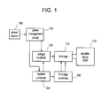
- variable-focus optic 112 may be a liquid lens that changes focal properties, e.g. focal length, in response to an activation voltage applied across two electrical terminals of the lens.
- the two terminals may correspond to a front-side and a back-side terminal of the optic 112.
- the activation voltage may be significantly higher than voltages available from the power source, for example, twenty-five (25) volts for full lens activation and a battery providing only two (2) volts.
- the power source 100 may be a battery, a capacitor or similar device providing stored charge at a usable working voltage. In some exemplary embodiments, the power source 100 may be an inductive power coupling to an external power supply.
- the power management circuit 102 may comprise one or more voltage regulators, voltage or current references, and switches to selectively enable power supplied to other components in the electronic lens system.
- the system controller 104 comprises a digital control system implemented as either a microcontroller running software, or in digital logic, such as a state machine and may further comprise an oscillator for generating a periodic timing signal for the control system.
- the system controller 104 provides control signals to the voltage multiplier 108 and to the H-bridge controller 106 based on an internal algorithm or under external control by a user (interface not shown).
- the voltage multiplier 108 receives current at a low working voltage from the power source 100 and generates a high output voltage at or above the activation voltage of the variable-focus optic 112, i.e. sufficient to change the state of the variable-focus optic 112.
- the voltage multiplier 108 may further comprise an oscillator or receive a clock signal from the system controller 104.
- the voltage multiplier 108 output is coupled to the variable-focus optic 112 through the H-bridge switch circuit 110, a circuit type widely known in the art.
- the H-bridge 110 comprises switches between the voltage multiplier 108 output and each of the variable-focus optic 112 terminals and between each of the variable-focus optic 112 terminals and an electrical ground of the system.
- the state of the H-bridge 110 is determined by one or more of the system controller 104 control signals applied to the H-bridge controller 106.
- the H-bridge controller 106 acts to interface the H-bridge 110 to the system controller 104.
- an H-bridge controller 106 will level-shift the control signals from a low-voltage digital controller, for example, system controller 104, which runs at a typical voltage of 1.8 volts, to the high-voltage H-bridge 110.
- the H-bridge controller 106 may also include timing and delay circuitry, circuitry to manage outputs to the H-bridge 110 with fewer inputs from the system controller 104, and circuitry to prevent problematic states in the H-bridge 110 such as shoot-through, a short-circuit condition known in the relevant art.
- the H-bridge 110 may be configured into one or more states such as with the lens terminals open, shorted to ground, or powered with one terminal coupled to the voltage multiplier 108 output and the other to ground, or powered in the opposite polarity.
- the H-bridge 110 provides a convenient method to energize the variable-focus optic 112 for actuation, discharge the variable-focus optic 112 to return it to a base power, and toggle the polarity of bias provided to the variable-focus optic 112.
- variable-focus optic Grounding both terminals of the variable-focus optic allows charge in the optic 112 to be quickly removed, thereby allowing the variable-focus optic 112 to quickly change to the unenergized focus state instead of suffering a long delay as charge slowly dissipates through a high-isolation system.
- the system controller 104 may periodically reverse the polarity of the H-bridge 110 output to optimize the performance of the variable-focus optic 112, for example, to avoid excessive charge trapping that may occur when powered in one state for too long.
- the functional block are shown and described for illustrative purposes only, and that functional blocks may be added, removed or substituted while still relying on the basic principles of a lens driver designed and configured specifically for use in an electronic or powered ophthalmic device as described herein.
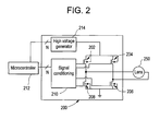
- FIG. 2 illustrates an exemplary H-bridge circuit 200 coupled to a powered ophthalmic lens having a variable-focus optic 250.
- the H-bridge circuit 200 is particularly useful for controlling the voltage potential applied to the variable-focus optic 250 and may be used to switch voltage to the variable-focus optic 250, reverse polarity across the variable-focus optic 250, and ground the variable-focus optic 250.
- the exemplary H-bridge 200 comprises metal-oxide-semiconductor field-effect transistor or MOSFET switches 202, 204, 206 and 208 which are controlled by a signal conditioning circuit 210 and microcontroller 212.
- the microcontroller 212 corresponds to the system controller 104
- the signal conditioning circuit 210 corresponds to the H-bridge controller 106 as illustrated in Figure 1 .
- the microcontroller 212 could be replaced by a state machine or other device capable of controlling the lens driver circuitry.
- the signal conditioning circuit 210 is the interface between the microcontroller 212 and the H-bridge, for example, shifting voltage from a 1.8 V logic level to the gate drive needed for a 25 V output. It is important to note that the low voltage logic level may be as low as about 0.9 volts and the high level gate drive voltages may vary between 13 to 60 volts.
- the variable-focus optic 250 connects to the outputs of the H-bridge.
- the H-bridge inputs connect to the high voltage generator 214 and to ground.
- the high voltage generator 214 may be a voltage multiplier, charge pump, or other circuit. Additional circuitry (not illustrated) may be required for implementation and control of the H-bridge 110 depending on the requirements thereof and the technology utilized for implementation thereof. For example, additional switches may be required depending on the high-voltage generator output level and the bias voltages available in the system.
- one side of the variable-focus optic 250 will be connected to ground while the other side is connected to the high voltage generator 214.
- the switches 202, 204, 206 and 208 forming the H-bridge are activated in the correct on/off combination. For example, if switches 202 and 206 are closed while switches 204 and 208 are open, the left side of the variable-focus optic 250 will connect to the high voltage generator 214 and the right side of the variable-focus optic 250 will connect to ground. This represents one case where the variable-focus optic 250 may be charged and thus activated.
- switches 202 and 204 are set open while switches 208 and 206 are closed.
- variable-focus optic 250 This eliminates any voltage potential across the variable-focus optic 250, which causes it to deactivate.
- Another potentially useful state is to apply a potential across the variable-focus optic 250, allow the variable-focus optic 250 to accumulate charge, then disconnect the variable-focus optic 250 and allow it to remain activated on stored charge only. This may be implemented by opening all switches 202, 204, 206 and 208 forming the H-bridge. Such a state may allow a further reduction in current consumption if the high voltage generator 214 is disabled while the variable-focus optic 250 is floating. Careful design of the variable-focus optic 250 capacitance and resistance, and leakage in the electronic system may allow the variable-focus optic 250 to store charge for many seconds, thereby greatly reducing the duty cycle of the high voltage generator 214 and hence the average current consumption.
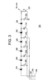
- FIG 3 illustrates a diagrammatic representation of an exemplary diode-base charge pump lens driver 300.
- the diode-base charge pump or charge pump 300 is powered and controlled from inputs 302, 304, and 306.
- the input 306 is a constant DC voltage source which is continuously on when the charge pump 300 is active. When the DC voltage source is switched off, the charge pump 300 is inactive to save on current consumption.
- Inputs 304 and 302 are preferably square wave signals of complementary polarity which pulse during operation. Figure 7 illustrates these signals.
- Inputs 302, 304, and 306 may be driven from a microcontroller, a hardware logic circuit or similar timing device, and typically have the same operating voltage as the control circuitry, for example 3.5 V.
- Capacitors 308, 314, and 318 form one side of the charge pump 300 and are connected to input 304.
- Capacitors 310 and 316 form the other side of the charge pump 300 and are controlled by input 302.
- Diodes 324, 326, 328, 330, 332, and 334 allow current to flow in only one direction, in this example, from left to right.
- a single stage of the charge pump 300 comprises a diode and the following capacitor, for example, 326 and 310. When voltage is applied to input 306, current flows through diode 324 and accumulates in capacitor 308.
- a lens load is placed in parallel with capacitor 320 and load resistor 322.
- the lens receives a much higher voltage, approximately 21 V, than is possible with a direct drive from the microcontroller at approximately 3.5 V. It is important to note that this voltage may vary between 18 V and 20 V.
- Figure 4 graphically illustrates a response of two variable-focus optics of two powered ophthalmic lenses to applied voltage across their terminals.
- a first variable-focus optic is a commercially available device comprising saline and oil with a substantially cylindrical shape.
- optical power of the variable-focus optic begins to increase once the applied voltage exceeds an activation voltage at a threshold reference point 404, in this example, approximately 16 V. It will be appreciated that this voltage is far in excess of that available from most single-cell battery chemistries.
- the first variable-focus optic has a linear response up to 46 V at endpoint reference 406.
- the first variable-focus optic At low voltages up to the threshold reference point 404, the first variable-focus optic is in the deactivated state and possesses a baseline optical power. Above the threshold voltage, the first variable-focus optic's optical power increases. The threshold voltage and function of optical power versus applied voltage will vary depending on variable-focus optic design.
- a second lens design optimized for presbyopia correction is illustrated with function 408.
- the second variable-focus optic is a custom saline and oil optic with a substantially spherical shape. Essentially, this second variable-focus optic differs from the first one described above in saline and oil chemistry, dielectric material and mechanical design and hence the different response as described herein.
- This second variable focus-optic has a second threshold reference point 410 reduced to approximately 12 V, perhaps through optimizations to the variable-focus optic's fluid, mechanics, and dielectric thickness. Further optimizations of both the variable-focus optic and lens driver may be possible due to the unique storage and runtime characteristics of an ophthalmic device versus those of a commercially available electronic variable-focus optic, one which must run operate for many years with wide changes in focal length.
- the second variable-focus optic saturates at +3 diopters with approximately 17 V applied at reference point 412. Above this saturation voltage the variable-focus optic power is no longer variable with applied voltage.
- a design for a presbyopic and baseline myopitc patient may default to a negative optical power for distance vision correction.
- variable-focus optic functions are possible based on the mechanical and chemical design of the variable-focus optic. It will be appreciated that above approximately 17 V, no change in optical power occurs. Correspondingly, a lens driver may be designed to reach 25 V with +/- 8 V of potential error, and such a lens driver would still fully activate the second variable-focus optic, perhaps with no observable difference between 17 V and 33 V. Accordingly, the lens driver may be designed for imprecise control and substantial variation over input voltage, temperature, semiconductor, and other parameters. Such design tradeoffs allow the lens driver to be implemented with a simpler circuit, one that consumes less power and area.
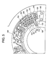
- FIG. 5 illustrates the layout of devices for an exemplary discrete lens driver circuit in accordance with the present invention on a circuit board 500.
- the circuit board 500 is preferably cut into the shape of an annular ring, thereby permitting it to be formed into a conical section for incorporation into a lens, for example, a contact lens or an intraocular lens.
- a microcontroller 550 drives a charge pump depending on internal programming and the state of various sensors. As described with respect to Figure 3 , diodes 502, 504, 506, 508, 510 and 512 block the reverse flow of current and allow charge to pass from one stage to the next in the charge pump.
- Capacitors 520 and 522 connect to the 302 input ( Figure 3 ) whereas capacitors 514, 516, and 518, connect to the 304 input ( Figure 3 ).
- Load capacitor 524 and load resistor 526 are present in parallel with the lens driver output.
- a trace and via 528 connect the lens driver output to a tab 530 on the circuit board 500. This tab 530 bends into position and may be attached to one side of the lens with conductive epoxy.
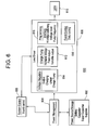
- system block diagram 600 illustrates how an exemplary lens driver interfaces with the electro-optical system.
- the exemplary system 600 comprises batteries 602 or any other suitable power source.
- the power source 602 is constrained for voltage and current by competing system requirements, for example, small size.
- the power source 602 is applied to a power management block 604 which may provide a regulated output, switch off the load at a defined battery cutoff threshold, allow for battery charging, and other suitable functions.
- a system control block 606 is responsible for event timing and activation. It may be implemented as a microcontroller, state machine, or other circuitry.
- the system control block 606 may include or interface with sensor circuitry to determine the desired variable-focus optic state.
- the lens driver 608 receives control signals from the system control block 606 and power from the power management block 604 or perhaps directly from the power source 602.
- a lens 610 connects to the lens driver 608.
- the lens driver 608 may comprise functions to increase voltage via a charge pump 612, regulate voltage via a voltage regulator 614, toggle polarity, ground the lens, float the lens, and the like via a programming interface and event control block 610 and 618 respectively.
- Waveform 700 is a constant DC voltage, for example 3.5 V from a battery. Signal 700 may be switched off when the charge pump is not in operation.
- Waveform 702 and 704 are complementary signals toggling between, for example, ground and 3.5 V. On one half-cycle, 702 is high while 704 is low. This causes one set of capacitors in the charge pump to charge. On the other half-cycle, 702 is low while 704 is high. This causes the other set of capacitors to charge. As each capacitor charges, a difference in voltage potential is created across the series diodes. The potential cannot create current flow towards the sources since the diodes prevent current flow in the reverse direction. The potential causes current to flow through the diodes toward the load. At each stage, the voltage is increased by approximately 3.5 V minus a loss factor.
- FIG 8 illustrates an alternate exemplary lens driver 800 using metal-oxide-semiconductor field-effect transistors (MOSFETs) connected as diodes instead of discrete diodes as was shown and described with respect to Figure 3 .
- MOSFETs metal-oxide-semiconductor field-effect transistors
- This implementation is more common in integrated circuits, although other circuits are possible and may be utilized for the lens driver in accordance with the present invention and described herein.
- Clock inputs 830 and 832 represent the complementary signals which drive the charge pump capacitors; namely, 302 and 304 illustrated in Figure 3 , and 702 and 704 illustrated in Figure 7 .
- a clock buffer stage 802 precludes the diodes and switches of the lens driver 800. Non-overlapping clocks are required to avoid shoot-through current in the switches and to ensure proper operation of the charge pump 800.
- non-overlapping clocks are defined in the simulation parameters. Those skilled in the art will appreciate that the clocks could be generated in a digital control block or with other non-overlapping clock generation circuitry known in the art.
- Supplies 826 and 828 represent the power supply input; namely, 306 illustrated in Figure 3 and 700 illustrated in Figure 7 .
- Capacitors 804, 806, 808, 810, 812, 814, 816, 818, 820, 822 and 824 are positioned between the MOSFETs 834, 836, 838, 840, 842, 844, 846, 848, 850, 852, 854 and 856.
- MOSFET switches 834 - 856 are illustrated as three terminal devices, understood to have their bulk terminals tied to ground.
- the MOSFETs would preferably be chosen appropriately from a library of devices in a special high-voltage semiconductor fabrication process. For example, such MOSFETs preferably have gate oxide and drain-source breakdown voltages sufficiently high to withstand the voltages created by the charge pump, as high as sixty (60) volts or more at the output. Standard devices used in typical complementary metal-oxide semiconductor (CMOS) processes would not have sufficient breakdown voltage capability for this exemplary lens driver.
- CMOS complementary metal-oxide semiconductor
- the driving waveforms including perhaps the gate and well biasing, must be appropriate for the circuit described.
- high-voltage, foundry-specific device models and driving circuitry are not shown in this illustration, those knowledgeable in the field will recognize the need to design appropriately with these devices.
- Figure 9 shows simulated voltage versus time at each capacitor's top plate node in the exemplary system of Figure 8 along with the final output voltage.
- the lens driver charges the load to approximately 43 V in ten (10) milliseconds.
- the load is two (2) gigaohms in parallel with one-hundred (100) picofarads, a model of the lens developed from laboratory measurements.
- the schematic shown in Figure 8 was operated at a clock frequency of 1 kHz with 1 pF for each stage's capacitor.
- the exemplary contact lens 1000 comprises a soft plastic portion 1002 which comprises an electronic insert 1004.
- This electronic insert 1004 includes a lens 1006 which is activated or controlled by the electronics described herein, for example, focusing near or far depending up activation.
- Circuitry 1008 mounts onto the insert 1004 and is connected to a power source 1010, such as batteries via one or more electrical interconnect traces 1012. Additional circuitry may also be connected via the electrical interconnect traces 1012.
- Circuitry 1008 may include any of the components set forth herein, including one or more sensors 1014.
- variable-focus lens system may be coupled directly to the power source or it may be coupled to the output of a voltage regulator.
- the system may comprise an H-bridge to provide flexible control of the lens terminal voltages, or the system may comprise only a simple switch to one terminal with the other terminal grounded, or it may comprise no switches with the lens always coupled in one way to the voltage multiplier output.
- Each variation may provide a different tradeoff between system cost, area and performance or efficiency.
- the electronics and electronic interconnections are made in the peripheral zone of a contact lens rather than in the optic zone.
- the positioning of the electronics need not be limited to the peripheral zone of the contact lens.
- All of the electronic components described herein may be fabricated utilizing thin-film technology and/or transparent materials. If these technologies are utilized, the electronic components may be placed in any suitable location as long as they are compatible with the optics.
- circuitry described herein may be implemented in hardware, software or a combination of hardware and software.
- circuit board utilized herein may comprise any suitable substrate, including copper traces on a flexible polyimide substrate with a nickel-gold surface finish.
Landscapes
- Health & Medical Sciences (AREA)
- Ophthalmology & Optometry (AREA)
- Physics & Mathematics (AREA)
- General Health & Medical Sciences (AREA)
- General Physics & Mathematics (AREA)
- Optics & Photonics (AREA)
- Biomedical Technology (AREA)
- Life Sciences & Earth Sciences (AREA)
- Transplantation (AREA)
- Engineering & Computer Science (AREA)
- Cardiology (AREA)
- Heart & Thoracic Surgery (AREA)
- Vascular Medicine (AREA)
- Oral & Maxillofacial Surgery (AREA)
- Animal Behavior & Ethology (AREA)
- Public Health (AREA)
- Veterinary Medicine (AREA)
- Prostheses (AREA)
- Eyeglasses (AREA)
- Liquid Crystal (AREA)
- Mechanical Light Control Or Optical Switches (AREA)
Applications Claiming Priority (2)
| Application Number | Priority Date | Filing Date | Title |
|---|---|---|---|
| US201261619524P | 2012-04-03 | 2012-04-03 | |
| US13/798,295 US9351827B2 (en) | 2012-04-03 | 2013-03-13 | Lens driver for variable-optic electronic ophthalmic lens |
Publications (2)
| Publication Number | Publication Date |
|---|---|
| EP2648031A1 true EP2648031A1 (fr) | 2013-10-09 |
| EP2648031B1 EP2648031B1 (fr) | 2019-02-20 |
Family
ID=48190701
Family Applications (1)
| Application Number | Title | Priority Date | Filing Date |
|---|---|---|---|
| EP13162192.2A Active EP2648031B1 (fr) | 2012-04-03 | 2013-04-03 | Pilote de lentille pour lentille ophtalmique électronique à optique variable |
Country Status (11)
| Country | Link |
|---|---|
| US (1) | US9351827B2 (fr) |
| EP (1) | EP2648031B1 (fr) |
| JP (1) | JP2013218326A (fr) |
| KR (1) | KR102068967B1 (fr) |
| CN (1) | CN103365028B (fr) |
| AU (1) | AU2013202240B2 (fr) |
| CA (1) | CA2810343A1 (fr) |
| IL (1) | IL225383B (fr) |
| RU (1) | RU2577461C2 (fr) |
| SG (1) | SG193747A1 (fr) |
| TW (1) | TWI582489B (fr) |
Cited By (4)
| Publication number | Priority date | Publication date | Assignee | Title |
|---|---|---|---|---|
| EP3047327A1 (fr) * | 2013-09-16 | 2016-07-27 | Verily Life Sciences LLC | Dispositif à double alimentation |
| EP3185419A1 (fr) * | 2015-12-22 | 2017-06-28 | Johnson & Johnson Vision Care Inc. | Circuit de commande de pont en h à haute tension pour un circuit d'attaque de lentille d'une lentille ophtalmique électronique |
| EP3695265A4 (fr) * | 2017-10-11 | 2021-07-07 | Verily Life Sciences LLC | Amplificateur de tension destiné à une lentille d'électromouillage |
| EP3745707A4 (fr) * | 2018-01-23 | 2021-09-22 | LG Innotek Co., Ltd. | Circuit de commande de lentille liquide, module de caméra, et procédé de commande de lentille liquide |
Families Citing this family (45)
| Publication number | Priority date | Publication date | Assignee | Title |
|---|---|---|---|---|
| US9931203B2 (en) * | 2011-08-02 | 2018-04-03 | Valdemar Portney | Presbyopia correcting wireless optical system |
| US10423011B2 (en) * | 2012-06-14 | 2019-09-24 | Mitsui Chemicals, Inc. | Lens, lens blank, and eyewear |
| US9442305B2 (en) | 2012-06-14 | 2016-09-13 | Mitsui Chemicals, Inc. | Electronic eyeglasses and methods of manufacturing |
| GB2508471B (en) * | 2012-11-29 | 2015-10-07 | Cooke Optics Ltd | Camera lens assembly |
| WO2014110190A2 (fr) * | 2013-01-09 | 2014-07-17 | Sloan Kettering Institute For Cancer Research | Prothèse oculaire ayant un dispositif d'affichage |
| US9052528B2 (en) | 2013-02-28 | 2015-06-09 | Johnson & Johnson Vision Care, Inc. | Electronic ophthalmic lens with multi-input voting scheme |
| US9933634B2 (en) * | 2014-06-13 | 2018-04-03 | Verily Life Sciences Llc | Apparatus, system and method for gaze tracking based on photodetection by an eye-mountable device |
| US9841614B2 (en) | 2014-06-13 | 2017-12-12 | Verily Life Sciences Llc | Flexible conductor for use within a contact lens |
| US9854437B1 (en) | 2014-06-13 | 2017-12-26 | Verily Life Sciences Llc | Apparatus, system and method for exchanging encrypted communications with an eye-mountable device |
| US9690118B2 (en) | 2014-06-13 | 2017-06-27 | Verily Life Sciences Llc | Eye-mountable device to provide automatic accommodation and method of making same |
| US9678361B2 (en) | 2014-06-13 | 2017-06-13 | Verily Life Sciences Llc | Power delivery for accommodation by an eye-mountable device |
| US9880401B2 (en) | 2014-06-13 | 2018-01-30 | Verily Life Sciences Llc | Method, device and system for accessing an eye-mountable device with a user interface |
| US10317702B2 (en) | 2014-06-13 | 2019-06-11 | Verily Life Sciences Llc | Failsafe operation of eye-mountable device |
| US9442311B2 (en) | 2014-06-13 | 2016-09-13 | Verily Life Sciences Llc | Contact lens with capacitive gaze tracking |
| US9442310B2 (en) | 2014-06-13 | 2016-09-13 | Verily Life Sciences Llc | Capacitive gaze tracking for auto-accommodation in a contact lens |
| EP2979662A1 (fr) * | 2014-08-01 | 2016-02-03 | Akkolens International B.V. | Lentille intraoculaire avec générateur d'électricité et systèmes fonctionnels supplémentaires |
| US20160056508A1 (en) * | 2014-08-21 | 2016-02-25 | Johnson & Johnson Vision Care, Inc. | Electrolyte formulations for use in biocompatible energization elements |
| US9535266B2 (en) * | 2014-11-05 | 2017-01-03 | Johnson & Johnson Vision Care, Inc. | Wake circuit for powered ophthalmic lens |
| US9612362B2 (en) * | 2015-01-27 | 2017-04-04 | Electronics And Telecommunications Research Institute | Thin active optical zoom lens and apparatus using the same |
| ES2969255T3 (es) | 2015-09-23 | 2024-05-17 | Ohio State Innovation Foundation | Lente de contacto que comprende una lenticular en una porción superior de la lente de contacto |
| US10191302B2 (en) * | 2015-09-23 | 2019-01-29 | Ohio State Innovation Foundation | Contact lens comprising lenticular-like curve |
| US10281743B2 (en) | 2015-10-01 | 2019-05-07 | Verily Life Sciences Llc | Eye convergence detection with contact lenses |
| US10222632B2 (en) | 2015-10-01 | 2019-03-05 | Verily Life Sciences Llc | Lens-to-lens communication for contact lenses |
| US10437129B2 (en) * | 2015-11-10 | 2019-10-08 | Verily Life Sciences Llc | Dynamic diffractive liquid crystal lens |
| US10859857B2 (en) | 2016-03-22 | 2020-12-08 | Johnson & Johnson Vision Care, Inc. | Pulsed plus lens designs for myopia control, enhanced depth of focus and presbyopia correction |
| US10908384B2 (en) | 2016-10-31 | 2021-02-02 | Lg Innotek Co., Ltd. | Circuit for controlling voltage for driving liquid lens and camera module and optical device comprising same |
| JP6174232B1 (ja) * | 2016-11-25 | 2017-08-02 | 株式会社ユニバーサルビュー | ピンホールコンタクトレンズ及びスマートコンタクトシステム |
| US10784877B2 (en) * | 2016-12-21 | 2020-09-22 | Johnson & Johnson Vision Care, Inc. | Extended period timer circuits for ophthalmic devices |
| US20180173013A1 (en) * | 2016-12-21 | 2018-06-21 | Johnson & Johnson Vision Care, Inc. | Electrode configuration for sensing ciliary impedance |
| US10345621B2 (en) | 2017-02-22 | 2019-07-09 | Johnson & Johnson Vision Care, Inc. | Electronic ophthalmic device with extreme gaze angle detection |
| EP3585309A4 (fr) | 2017-04-06 | 2020-09-02 | Teardx LLC | Dispositifs oculaires et leurs procédés d'utilisation |
| CN114019683A (zh) * | 2017-05-17 | 2022-02-08 | 苹果公司 | 具有视力矫正的头戴式显示设备 |
| US10617567B2 (en) * | 2017-06-10 | 2020-04-14 | Manjinder Saini | Intraocular implant device |
| US11547608B2 (en) | 2017-06-10 | 2023-01-10 | Manjinder Saini | Comprehensive intraocular vision advancement |
| CN207198496U (zh) * | 2017-08-02 | 2018-04-06 | 江门亿都半导体有限公司 | 一种低功耗自动感光太阳眼镜 |
| US11320673B2 (en) | 2017-09-01 | 2022-05-03 | Ohio State Innovation Foundation | Soft contact lens comprising a lenticular in a superior portion of the contact lens with enhanced tear exchange |
| US11567242B2 (en) | 2017-11-15 | 2023-01-31 | Corning Incorporated/LG Innotek Co. LTD. | Liquid lens systems |
| KR102552516B1 (ko) * | 2018-01-23 | 2023-07-11 | 엘지이노텍 주식회사 | 감지된 온도 정보를 이용하여 렌즈 곡률을 가변하는 렌즈 곡률 가변 장치, 이를 구비하는 카메라, 및 영상표시장치 |
| US20190346692A1 (en) * | 2018-05-09 | 2019-11-14 | Johnson & Johnson Vision Care, Inc. | Electronic ophthalmic lens for measuring distance using ultrasound time-of-flight |
| US11126055B2 (en) | 2018-07-10 | 2021-09-21 | Verily Life Sciences Llc | Switching of liquid crystal device |
| US11681164B2 (en) | 2018-07-27 | 2023-06-20 | Tectus Corporation | Electrical interconnects within electronic contact lenses |
| US20200064660A1 (en) * | 2018-08-24 | 2020-02-27 | Johnson & Johnson Vision Care, Inc. | Optical communication of ophthalmic devices |
| US11733546B1 (en) | 2019-03-01 | 2023-08-22 | Verily Life Sciences Llc | Wirelessly loaded impedance sensor for self-test |
| US11237410B2 (en) | 2019-08-28 | 2022-02-01 | Tectus Corporation | Electronics assembly for use in electronic contact lens |
| US11809019B2 (en) * | 2021-01-08 | 2023-11-07 | Tectus Corporation | Contact lens power supply with movable generator |
Citations (4)
| Publication number | Priority date | Publication date | Assignee | Title |
|---|---|---|---|---|
| EP1760515A2 (fr) * | 2003-10-03 | 2007-03-07 | Invisia Ltd. | Lentille ophtalmique multifocale |
| US20100076553A1 (en) * | 2008-09-22 | 2010-03-25 | Pugh Randall B | Energized ophthalmic lens |
| WO2010051225A1 (fr) * | 2008-10-31 | 2010-05-06 | Johnson & Johnson Vision Care, Inc. | Procédé et appareil pour former une lentille ophtalmologique avec micro-dispositif de commande incorporé |
| WO2011163080A1 (fr) * | 2010-06-20 | 2011-12-29 | Elenza, Inc. | Dispositifs ophtalmiques et procédés avec circuits intégrés à application spécifique |
Family Cites Families (10)
| Publication number | Priority date | Publication date | Assignee | Title |
|---|---|---|---|---|
| US5807944A (en) * | 1996-06-27 | 1998-09-15 | Ciba Vision Corporation | Amphiphilic, segmented copolymer of controlled morphology and ophthalmic devices including contact lenses made therefrom |
| US6477410B1 (en) * | 2000-05-31 | 2002-11-05 | Biophoretic Therapeutic Systems, Llc | Electrokinetic delivery of medicaments |
| EP1673656B1 (fr) * | 2003-10-03 | 2007-01-17 | Invisia Ltd. | Verre multifoyer |
| US7018039B2 (en) * | 2003-11-14 | 2006-03-28 | Synergeyes,Inc. | Contact lens |
| US9804295B2 (en) * | 2005-05-05 | 2017-10-31 | Novartis Ag | Ophthalmic devices for sustained delivery of active compounds |
| US20070260307A1 (en) | 2006-05-05 | 2007-11-08 | Azar Dimitri T | Vision prosthesis with implantable power source |
| AR064985A1 (es) * | 2007-01-22 | 2009-05-06 | E Vision Llc | Lente electroactivo flexible |
| US9296158B2 (en) * | 2008-09-22 | 2016-03-29 | Johnson & Johnson Vision Care, Inc. | Binder of energized components in an ophthalmic lens |
| US9375885B2 (en) * | 2008-10-31 | 2016-06-28 | Johnson & Johnson Vision Care, Inc. | Processor controlled ophthalmic device |
| CN102804032B (zh) * | 2009-12-04 | 2015-09-09 | 派诺特公司 | 电控聚焦眼科装置 |
-
2013
- 2013-03-13 US US13/798,295 patent/US9351827B2/en active Active
- 2013-03-21 IL IL225383A patent/IL225383B/en active IP Right Grant
- 2013-03-22 SG SG2013021043A patent/SG193747A1/en unknown
- 2013-03-25 CA CA2810343A patent/CA2810343A1/fr not_active Abandoned
- 2013-04-02 TW TW102111808A patent/TWI582489B/zh active
- 2013-04-02 AU AU2013202240A patent/AU2013202240B2/en not_active Ceased
- 2013-04-02 KR KR1020130035647A patent/KR102068967B1/ko active IP Right Grant
- 2013-04-02 JP JP2013076696A patent/JP2013218326A/ja active Pending
- 2013-04-02 RU RU2013114871/14A patent/RU2577461C2/ru not_active IP Right Cessation
- 2013-04-03 CN CN201310116073.2A patent/CN103365028B/zh active Active
- 2013-04-03 EP EP13162192.2A patent/EP2648031B1/fr active Active
Patent Citations (4)
| Publication number | Priority date | Publication date | Assignee | Title |
|---|---|---|---|---|
| EP1760515A2 (fr) * | 2003-10-03 | 2007-03-07 | Invisia Ltd. | Lentille ophtalmique multifocale |
| US20100076553A1 (en) * | 2008-09-22 | 2010-03-25 | Pugh Randall B | Energized ophthalmic lens |
| WO2010051225A1 (fr) * | 2008-10-31 | 2010-05-06 | Johnson & Johnson Vision Care, Inc. | Procédé et appareil pour former une lentille ophtalmologique avec micro-dispositif de commande incorporé |
| WO2011163080A1 (fr) * | 2010-06-20 | 2011-12-29 | Elenza, Inc. | Dispositifs ophtalmiques et procédés avec circuits intégrés à application spécifique |
Cited By (10)
| Publication number | Priority date | Publication date | Assignee | Title |
|---|---|---|---|---|
| EP3047327A1 (fr) * | 2013-09-16 | 2016-07-27 | Verily Life Sciences LLC | Dispositif à double alimentation |
| EP3047327A4 (fr) * | 2013-09-16 | 2017-05-03 | Verily Life Sciences LLC | Dispositif à double alimentation |
| US9692230B2 (en) | 2013-09-16 | 2017-06-27 | Verily Life Sciences Llc | Device with dual power sources |
| EP3185419A1 (fr) * | 2015-12-22 | 2017-06-28 | Johnson & Johnson Vision Care Inc. | Circuit de commande de pont en h à haute tension pour un circuit d'attaque de lentille d'une lentille ophtalmique électronique |
| US9904075B2 (en) | 2015-12-22 | 2018-02-27 | Johnson & Johnson Vision Care, Inc. | High-voltage H-bridge control circuit for a lens driver of an electronic ophthalmic lens |
| US10216009B2 (en) | 2015-12-22 | 2019-02-26 | Johnson & Johnson Vision Care, Inc. | High-voltage H-bridge control circuit for a lens driver of an electronic ophthalmic lens |
| EP3695265A4 (fr) * | 2017-10-11 | 2021-07-07 | Verily Life Sciences LLC | Amplificateur de tension destiné à une lentille d'électromouillage |
| US11394296B2 (en) | 2017-10-11 | 2022-07-19 | Verily Life Sciences Llc | Voltage driver for electrowetting lens |
| EP3745707A4 (fr) * | 2018-01-23 | 2021-09-22 | LG Innotek Co., Ltd. | Circuit de commande de lentille liquide, module de caméra, et procédé de commande de lentille liquide |
| US11968434B2 (en) | 2018-01-23 | 2024-04-23 | Lg Innotek Co., Ltd. | Camera module having a liquid lens and a voltage control circuit |
Also Published As
| Publication number | Publication date |
|---|---|
| SG193747A1 (en) | 2013-10-30 |
| US20130258275A1 (en) | 2013-10-03 |
| RU2013114871A (ru) | 2014-10-10 |
| KR20130112768A (ko) | 2013-10-14 |
| TWI582489B (zh) | 2017-05-11 |
| IL225383B (en) | 2019-03-31 |
| CN103365028A (zh) | 2013-10-23 |
| JP2013218326A (ja) | 2013-10-24 |
| AU2013202240B2 (en) | 2017-01-19 |
| KR102068967B1 (ko) | 2020-01-22 |
| TW201350966A (zh) | 2013-12-16 |
| CA2810343A1 (fr) | 2013-10-03 |
| AU2013202240A1 (en) | 2013-10-17 |
| EP2648031B1 (fr) | 2019-02-20 |
| US9351827B2 (en) | 2016-05-31 |
| IL225383A0 (en) | 2013-07-31 |
| CN103365028B (zh) | 2018-09-11 |
| RU2577461C2 (ru) | 2016-03-20 |
Similar Documents
| Publication | Publication Date | Title |
|---|---|---|
| US9351827B2 (en) | Lens driver for variable-optic electronic ophthalmic lens | |
| US10216009B2 (en) | High-voltage H-bridge control circuit for a lens driver of an electronic ophthalmic lens | |
| US20180263759A1 (en) | System controller for variable-optic electronic ophthalmic lens | |
| US9535266B2 (en) | Wake circuit for powered ophthalmic lens | |
| US11394296B2 (en) | Voltage driver for electrowetting lens | |
| BR102013007949A2 (pt) | Acionador de lente para lente oftálmica eletrônica de óptica variável | |
| BR102016030066A2 (pt) | High-voltage h-bridge control circuit for a lens trigger of an electronic optalmic lens |
Legal Events
| Date | Code | Title | Description |
|---|---|---|---|
| PUAI | Public reference made under article 153(3) epc to a published international application that has entered the european phase |
Free format text: ORIGINAL CODE: 0009012 |
|
| AK | Designated contracting states |
Kind code of ref document: A1 Designated state(s): AL AT BE BG CH CY CZ DE DK EE ES FI FR GB GR HR HU IE IS IT LI LT LU LV MC MK MT NL NO PL PT RO RS SE SI SK SM TR |
|
| AX | Request for extension of the european patent |
Extension state: BA ME |
|
| 17P | Request for examination filed |
Effective date: 20140409 |
|
| RBV | Designated contracting states (corrected) |
Designated state(s): AL AT BE BG CH CY CZ DE DK EE ES FI FR GB GR HR HU IE IS IT LI LT LU LV MC MK MT NL NO PL PT RO RS SE SI SK SM TR |
|
| REG | Reference to a national code |
Ref country code: HK Ref legal event code: DE Ref document number: 1190201 Country of ref document: HK |
|
| GRAP | Despatch of communication of intention to grant a patent |
Free format text: ORIGINAL CODE: EPIDOSNIGR1 |
|
| STAA | Information on the status of an ep patent application or granted ep patent |
Free format text: STATUS: GRANT OF PATENT IS INTENDED |
|
| INTG | Intention to grant announced |
Effective date: 20180824 |
|
| GRAJ | Information related to disapproval of communication of intention to grant by the applicant or resumption of examination proceedings by the epo deleted |
Free format text: ORIGINAL CODE: EPIDOSDIGR1 |
|
| STAA | Information on the status of an ep patent application or granted ep patent |
Free format text: STATUS: REQUEST FOR EXAMINATION WAS MADE |
|
| GRAR | Information related to intention to grant a patent recorded |
Free format text: ORIGINAL CODE: EPIDOSNIGR71 |
|
| GRAS | Grant fee paid |
Free format text: ORIGINAL CODE: EPIDOSNIGR3 |
|
| STAA | Information on the status of an ep patent application or granted ep patent |
Free format text: STATUS: GRANT OF PATENT IS INTENDED |
|
| GRAA | (expected) grant |
Free format text: ORIGINAL CODE: 0009210 |
|
| STAA | Information on the status of an ep patent application or granted ep patent |
Free format text: STATUS: THE PATENT HAS BEEN GRANTED |
|
| INTC | Intention to grant announced (deleted) | ||
| AK | Designated contracting states |
Kind code of ref document: B1 Designated state(s): AL AT BE BG CH CY CZ DE DK EE ES FI FR GB GR HR HU IE IS IT LI LT LU LV MC MK MT NL NO PL PT RO RS SE SI SK SM TR |
|
| INTG | Intention to grant announced |
Effective date: 20190115 |
|
| REG | Reference to a national code |
Ref country code: GB Ref legal event code: FG4D |
|
| REG | Reference to a national code |
Ref country code: CH Ref legal event code: EP |
|
| REG | Reference to a national code |
Ref country code: DE Ref legal event code: R096 Ref document number: 602013050893 Country of ref document: DE |
|
| REG | Reference to a national code |
Ref country code: AT Ref legal event code: REF Ref document number: 1098983 Country of ref document: AT Kind code of ref document: T Effective date: 20190315 |
|
| REG | Reference to a national code |
Ref country code: IE Ref legal event code: FG4D |
|
| REG | Reference to a national code |
Ref country code: SE Ref legal event code: TRGR |
|
| REG | Reference to a national code |
Ref country code: NL Ref legal event code: MP Effective date: 20190220 |
|
| REG | Reference to a national code |
Ref country code: LT Ref legal event code: MG4D |
|
| PG25 | Lapsed in a contracting state [announced via postgrant information from national office to epo] |
Ref country code: FI Free format text: LAPSE BECAUSE OF FAILURE TO SUBMIT A TRANSLATION OF THE DESCRIPTION OR TO PAY THE FEE WITHIN THE PRESCRIBED TIME-LIMIT Effective date: 20190220 Ref country code: NO Free format text: LAPSE BECAUSE OF FAILURE TO SUBMIT A TRANSLATION OF THE DESCRIPTION OR TO PAY THE FEE WITHIN THE PRESCRIBED TIME-LIMIT Effective date: 20190520 Ref country code: NL Free format text: LAPSE BECAUSE OF FAILURE TO SUBMIT A TRANSLATION OF THE DESCRIPTION OR TO PAY THE FEE WITHIN THE PRESCRIBED TIME-LIMIT Effective date: 20190220 Ref country code: LT Free format text: LAPSE BECAUSE OF FAILURE TO SUBMIT A TRANSLATION OF THE DESCRIPTION OR TO PAY THE FEE WITHIN THE PRESCRIBED TIME-LIMIT Effective date: 20190220 Ref country code: PT Free format text: LAPSE BECAUSE OF FAILURE TO SUBMIT A TRANSLATION OF THE DESCRIPTION OR TO PAY THE FEE WITHIN THE PRESCRIBED TIME-LIMIT Effective date: 20190620 |
|
| PG25 | Lapsed in a contracting state [announced via postgrant information from national office to epo] |
Ref country code: LV Free format text: LAPSE BECAUSE OF FAILURE TO SUBMIT A TRANSLATION OF THE DESCRIPTION OR TO PAY THE FEE WITHIN THE PRESCRIBED TIME-LIMIT Effective date: 20190220 Ref country code: RS Free format text: LAPSE BECAUSE OF FAILURE TO SUBMIT A TRANSLATION OF THE DESCRIPTION OR TO PAY THE FEE WITHIN THE PRESCRIBED TIME-LIMIT Effective date: 20190220 Ref country code: BG Free format text: LAPSE BECAUSE OF FAILURE TO SUBMIT A TRANSLATION OF THE DESCRIPTION OR TO PAY THE FEE WITHIN THE PRESCRIBED TIME-LIMIT Effective date: 20190520 Ref country code: GR Free format text: LAPSE BECAUSE OF FAILURE TO SUBMIT A TRANSLATION OF THE DESCRIPTION OR TO PAY THE FEE WITHIN THE PRESCRIBED TIME-LIMIT Effective date: 20190521 Ref country code: IS Free format text: LAPSE BECAUSE OF FAILURE TO SUBMIT A TRANSLATION OF THE DESCRIPTION OR TO PAY THE FEE WITHIN THE PRESCRIBED TIME-LIMIT Effective date: 20190620 Ref country code: HR Free format text: LAPSE BECAUSE OF FAILURE TO SUBMIT A TRANSLATION OF THE DESCRIPTION OR TO PAY THE FEE WITHIN THE PRESCRIBED TIME-LIMIT Effective date: 20190220 |
|
| PGFP | Annual fee paid to national office [announced via postgrant information from national office to epo] |
Ref country code: SE Payment date: 20190410 Year of fee payment: 7 |
|
| REG | Reference to a national code |
Ref country code: AT Ref legal event code: MK05 Ref document number: 1098983 Country of ref document: AT Kind code of ref document: T Effective date: 20190220 |
|
| PG25 | Lapsed in a contracting state [announced via postgrant information from national office to epo] |
Ref country code: ES Free format text: LAPSE BECAUSE OF FAILURE TO SUBMIT A TRANSLATION OF THE DESCRIPTION OR TO PAY THE FEE WITHIN THE PRESCRIBED TIME-LIMIT Effective date: 20190220 Ref country code: DK Free format text: LAPSE BECAUSE OF FAILURE TO SUBMIT A TRANSLATION OF THE DESCRIPTION OR TO PAY THE FEE WITHIN THE PRESCRIBED TIME-LIMIT Effective date: 20190220 Ref country code: AL Free format text: LAPSE BECAUSE OF FAILURE TO SUBMIT A TRANSLATION OF THE DESCRIPTION OR TO PAY THE FEE WITHIN THE PRESCRIBED TIME-LIMIT Effective date: 20190220 Ref country code: SK Free format text: LAPSE BECAUSE OF FAILURE TO SUBMIT A TRANSLATION OF THE DESCRIPTION OR TO PAY THE FEE WITHIN THE PRESCRIBED TIME-LIMIT Effective date: 20190220 Ref country code: RO Free format text: LAPSE BECAUSE OF FAILURE TO SUBMIT A TRANSLATION OF THE DESCRIPTION OR TO PAY THE FEE WITHIN THE PRESCRIBED TIME-LIMIT Effective date: 20190220 Ref country code: CZ Free format text: LAPSE BECAUSE OF FAILURE TO SUBMIT A TRANSLATION OF THE DESCRIPTION OR TO PAY THE FEE WITHIN THE PRESCRIBED TIME-LIMIT Effective date: 20190220 Ref country code: EE Free format text: LAPSE BECAUSE OF FAILURE TO SUBMIT A TRANSLATION OF THE DESCRIPTION OR TO PAY THE FEE WITHIN THE PRESCRIBED TIME-LIMIT Effective date: 20190220 |
|
| REG | Reference to a national code |
Ref country code: DE Ref legal event code: R097 Ref document number: 602013050893 Country of ref document: DE |
|
| PG25 | Lapsed in a contracting state [announced via postgrant information from national office to epo] |
Ref country code: SM Free format text: LAPSE BECAUSE OF FAILURE TO SUBMIT A TRANSLATION OF THE DESCRIPTION OR TO PAY THE FEE WITHIN THE PRESCRIBED TIME-LIMIT Effective date: 20190220 Ref country code: PL Free format text: LAPSE BECAUSE OF FAILURE TO SUBMIT A TRANSLATION OF THE DESCRIPTION OR TO PAY THE FEE WITHIN THE PRESCRIBED TIME-LIMIT Effective date: 20190220 |
|
| REG | Reference to a national code |
Ref country code: CH Ref legal event code: PL |
|
| REG | Reference to a national code |
Ref country code: BE Ref legal event code: MM Effective date: 20190430 |
|
| PLBE | No opposition filed within time limit |
Free format text: ORIGINAL CODE: 0009261 |
|
| STAA | Information on the status of an ep patent application or granted ep patent |
Free format text: STATUS: NO OPPOSITION FILED WITHIN TIME LIMIT |
|
| PG25 | Lapsed in a contracting state [announced via postgrant information from national office to epo] |
Ref country code: MC Free format text: LAPSE BECAUSE OF FAILURE TO SUBMIT A TRANSLATION OF THE DESCRIPTION OR TO PAY THE FEE WITHIN THE PRESCRIBED TIME-LIMIT Effective date: 20190220 Ref country code: LU Free format text: LAPSE BECAUSE OF NON-PAYMENT OF DUE FEES Effective date: 20190403 Ref country code: AT Free format text: LAPSE BECAUSE OF FAILURE TO SUBMIT A TRANSLATION OF THE DESCRIPTION OR TO PAY THE FEE WITHIN THE PRESCRIBED TIME-LIMIT Effective date: 20190220 |
|
| 26N | No opposition filed |
Effective date: 20191121 |
|
| PG25 | Lapsed in a contracting state [announced via postgrant information from national office to epo] |
Ref country code: LI Free format text: LAPSE BECAUSE OF NON-PAYMENT OF DUE FEES Effective date: 20190430 Ref country code: CH Free format text: LAPSE BECAUSE OF NON-PAYMENT OF DUE FEES Effective date: 20190430 |
|
| PG25 | Lapsed in a contracting state [announced via postgrant information from national office to epo] |
Ref country code: BE Free format text: LAPSE BECAUSE OF NON-PAYMENT OF DUE FEES Effective date: 20190430 Ref country code: SI Free format text: LAPSE BECAUSE OF FAILURE TO SUBMIT A TRANSLATION OF THE DESCRIPTION OR TO PAY THE FEE WITHIN THE PRESCRIBED TIME-LIMIT Effective date: 20190220 |
|
| PG25 | Lapsed in a contracting state [announced via postgrant information from national office to epo] |
Ref country code: TR Free format text: LAPSE BECAUSE OF FAILURE TO SUBMIT A TRANSLATION OF THE DESCRIPTION OR TO PAY THE FEE WITHIN THE PRESCRIBED TIME-LIMIT Effective date: 20190220 |
|
| PG25 | Lapsed in a contracting state [announced via postgrant information from national office to epo] |
Ref country code: SE Free format text: LAPSE BECAUSE OF NON-PAYMENT OF DUE FEES Effective date: 20200404 |
|
| PG25 | Lapsed in a contracting state [announced via postgrant information from national office to epo] |
Ref country code: CY Free format text: LAPSE BECAUSE OF FAILURE TO SUBMIT A TRANSLATION OF THE DESCRIPTION OR TO PAY THE FEE WITHIN THE PRESCRIBED TIME-LIMIT Effective date: 20190220 |
|
| PG25 | Lapsed in a contracting state [announced via postgrant information from national office to epo] |
Ref country code: MT Free format text: LAPSE BECAUSE OF FAILURE TO SUBMIT A TRANSLATION OF THE DESCRIPTION OR TO PAY THE FEE WITHIN THE PRESCRIBED TIME-LIMIT Effective date: 20190220 Ref country code: HU Free format text: LAPSE BECAUSE OF FAILURE TO SUBMIT A TRANSLATION OF THE DESCRIPTION OR TO PAY THE FEE WITHIN THE PRESCRIBED TIME-LIMIT; INVALID AB INITIO Effective date: 20130403 |
|
| PG25 | Lapsed in a contracting state [announced via postgrant information from national office to epo] |
Ref country code: MK Free format text: LAPSE BECAUSE OF FAILURE TO SUBMIT A TRANSLATION OF THE DESCRIPTION OR TO PAY THE FEE WITHIN THE PRESCRIBED TIME-LIMIT Effective date: 20190220 |
|
| PGFP | Annual fee paid to national office [announced via postgrant information from national office to epo] |
Ref country code: IE Payment date: 20230310 Year of fee payment: 11 Ref country code: FR Payment date: 20230309 Year of fee payment: 11 |
|
| PGFP | Annual fee paid to national office [announced via postgrant information from national office to epo] |
Ref country code: IT Payment date: 20230310 Year of fee payment: 11 Ref country code: GB Payment date: 20230302 Year of fee payment: 11 |
|
| PGFP | Annual fee paid to national office [announced via postgrant information from national office to epo] |
Ref country code: DE Payment date: 20240306 Year of fee payment: 12 |