EP2648016A2 - Circumferential laser crawler - Google Patents
Circumferential laser crawler Download PDFInfo
- Publication number
- EP2648016A2 EP2648016A2 EP20130161740 EP13161740A EP2648016A2 EP 2648016 A2 EP2648016 A2 EP 2648016A2 EP 20130161740 EP20130161740 EP 20130161740 EP 13161740 A EP13161740 A EP 13161740A EP 2648016 A2 EP2648016 A2 EP 2648016A2
- Authority
- EP
- European Patent Office
- Prior art keywords
- wheels
- laser
- crawler
- motorized device
- reflector
- Prior art date
- Legal status (The legal status is an assumption and is not a legal conclusion. Google has not performed a legal analysis and makes no representation as to the accuracy of the status listed.)
- Granted
Links
Images


Classifications
-
- G—PHYSICS
- G01—MEASURING; TESTING
- G01B—MEASURING LENGTH, THICKNESS OR SIMILAR LINEAR DIMENSIONS; MEASURING ANGLES; MEASURING AREAS; MEASURING IRREGULARITIES OF SURFACES OR CONTOURS
- G01B11/00—Measuring arrangements characterised by the use of optical techniques
- G01B11/02—Measuring arrangements characterised by the use of optical techniques for measuring length, width or thickness
- G01B11/03—Measuring arrangements characterised by the use of optical techniques for measuring length, width or thickness by measuring coordinates of points
-
- G—PHYSICS
- G01—MEASURING; TESTING
- G01B—MEASURING LENGTH, THICKNESS OR SIMILAR LINEAR DIMENSIONS; MEASURING ANGLES; MEASURING AREAS; MEASURING IRREGULARITIES OF SURFACES OR CONTOURS
- G01B11/00—Measuring arrangements characterised by the use of optical techniques
- G01B11/24—Measuring arrangements characterised by the use of optical techniques for measuring contours or curvatures
-
- B—PERFORMING OPERATIONS; TRANSPORTING
- B64—AIRCRAFT; AVIATION; COSMONAUTICS
- B64F—GROUND OR AIRCRAFT-CARRIER-DECK INSTALLATIONS SPECIALLY ADAPTED FOR USE IN CONNECTION WITH AIRCRAFT; DESIGNING, MANUFACTURING, ASSEMBLING, CLEANING, MAINTAINING OR REPAIRING AIRCRAFT, NOT OTHERWISE PROVIDED FOR; HANDLING, TRANSPORTING, TESTING OR INSPECTING AIRCRAFT COMPONENTS, NOT OTHERWISE PROVIDED FOR
- B64F5/00—Designing, manufacturing, assembling, cleaning, maintaining or repairing aircraft, not otherwise provided for; Handling, transporting, testing or inspecting aircraft components, not otherwise provided for
- B64F5/10—Manufacturing or assembling aircraft, e.g. jigs therefor
-
- B—PERFORMING OPERATIONS; TRANSPORTING
- B64—AIRCRAFT; AVIATION; COSMONAUTICS
- B64F—GROUND OR AIRCRAFT-CARRIER-DECK INSTALLATIONS SPECIALLY ADAPTED FOR USE IN CONNECTION WITH AIRCRAFT; DESIGNING, MANUFACTURING, ASSEMBLING, CLEANING, MAINTAINING OR REPAIRING AIRCRAFT, NOT OTHERWISE PROVIDED FOR; HANDLING, TRANSPORTING, TESTING OR INSPECTING AIRCRAFT COMPONENTS, NOT OTHERWISE PROVIDED FOR
- B64F5/00—Designing, manufacturing, assembling, cleaning, maintaining or repairing aircraft, not otherwise provided for; Handling, transporting, testing or inspecting aircraft components, not otherwise provided for
- B64F5/60—Testing or inspecting aircraft components or systems
-
- G—PHYSICS
- G01—MEASURING; TESTING
- G01B—MEASURING LENGTH, THICKNESS OR SIMILAR LINEAR DIMENSIONS; MEASURING ANGLES; MEASURING AREAS; MEASURING IRREGULARITIES OF SURFACES OR CONTOURS
- G01B11/00—Measuring arrangements characterised by the use of optical techniques
- G01B11/24—Measuring arrangements characterised by the use of optical techniques for measuring contours or curvatures
- G01B11/2408—Measuring arrangements characterised by the use of optical techniques for measuring contours or curvatures for measuring roundness
-
- G—PHYSICS
- G01—MEASURING; TESTING
- G01C—MEASURING DISTANCES, LEVELS OR BEARINGS; SURVEYING; NAVIGATION; GYROSCOPIC INSTRUMENTS; PHOTOGRAMMETRY OR VIDEOGRAMMETRY
- G01C15/00—Surveying instruments or accessories not provided for in groups G01C1/00 - G01C13/00
- G01C15/002—Active optical surveying means
-
- G—PHYSICS
- G01—MEASURING; TESTING
- G01N—INVESTIGATING OR ANALYSING MATERIALS BY DETERMINING THEIR CHEMICAL OR PHYSICAL PROPERTIES
- G01N21/00—Investigating or analysing materials by the use of optical means, i.e. using sub-millimetre waves, infrared, visible or ultraviolet light
- G01N21/84—Systems specially adapted for particular applications
- G01N21/88—Investigating the presence of flaws or contamination
- G01N21/95—Investigating the presence of flaws or contamination characterised by the material or shape of the object to be examined
- G01N21/9515—Objects of complex shape, e.g. examined with use of a surface follower device
-
- G—PHYSICS
- G01—MEASURING; TESTING
- G01S—RADIO DIRECTION-FINDING; RADIO NAVIGATION; DETERMINING DISTANCE OR VELOCITY BY USE OF RADIO WAVES; LOCATING OR PRESENCE-DETECTING BY USE OF THE REFLECTION OR RERADIATION OF RADIO WAVES; ANALOGOUS ARRANGEMENTS USING OTHER WAVES
- G01S17/00—Systems using the reflection or reradiation of electromagnetic waves other than radio waves, e.g. lidar systems
- G01S17/66—Tracking systems using electromagnetic waves other than radio waves
-
- G—PHYSICS
- G01—MEASURING; TESTING
- G01S—RADIO DIRECTION-FINDING; RADIO NAVIGATION; DETERMINING DISTANCE OR VELOCITY BY USE OF RADIO WAVES; LOCATING OR PRESENCE-DETECTING BY USE OF THE REFLECTION OR RERADIATION OF RADIO WAVES; ANALOGOUS ARRANGEMENTS USING OTHER WAVES
- G01S7/00—Details of systems according to groups G01S13/00, G01S15/00, G01S17/00
- G01S7/48—Details of systems according to groups G01S13/00, G01S15/00, G01S17/00 of systems according to group G01S17/00
- G01S7/481—Constructional features, e.g. arrangements of optical elements
-
- G—PHYSICS
- G06—COMPUTING OR CALCULATING; COUNTING
- G06F—ELECTRIC DIGITAL DATA PROCESSING
- G06F30/00—Computer-aided design [CAD]
-
- G—PHYSICS
- G01—MEASURING; TESTING
- G01N—INVESTIGATING OR ANALYSING MATERIALS BY DETERMINING THEIR CHEMICAL OR PHYSICAL PROPERTIES
- G01N21/00—Investigating or analysing materials by the use of optical means, i.e. using sub-millimetre waves, infrared, visible or ultraviolet light
- G01N21/84—Systems specially adapted for particular applications
- G01N21/88—Investigating the presence of flaws or contamination
- G01N21/95—Investigating the presence of flaws or contamination characterised by the material or shape of the object to be examined
- G01N21/9515—Objects of complex shape, e.g. examined with use of a surface follower device
- G01N2021/9518—Objects of complex shape, e.g. examined with use of a surface follower device using a surface follower, e.g. robot
-
- G—PHYSICS
- G01—MEASURING; TESTING
- G01N—INVESTIGATING OR ANALYSING MATERIALS BY DETERMINING THEIR CHEMICAL OR PHYSICAL PROPERTIES
- G01N2291/00—Indexing codes associated with group G01N29/00
- G01N2291/26—Scanned objects
- G01N2291/269—Various geometry objects
- G01N2291/2694—Wings or other aircraft parts
Definitions
- the use of the combination of the laser tracker 210 and the crawler 200 may enable capturing measurement data at much higher rate, in time and/or distance.
- the laser tracker 210 may, for example, obtain measurement related readings in as small as a fraction of a second and/or at very small spatial intervals (e.g., every tenth).
- FIG. 3 is a diagram illustrating a circumferential laser crawler, in accordance with an advantageous embodiment of the invention. Referring to FIG. 3 , there is shown the crawler 200 of FIG. 2 . Also shown in FIG. 3 is a user controller 370.
- the first set 520A and the second set 520B may be configured to incorporate a tracking adjustment, to allow these sets to move laterally relative to one another, so that both sets may independently try to remain in contact with the traversed edge, even when the edge is uneven-e.g., when the edge is slanted or angled.
- allowing the first set 520A and the second set 520B to offset laterally may ensure that these sets may independently remain as tightly secured to the edge as possible, whereas not allowing such lateral offsetting may otherwise cause one of these sets to move away or dislodge from the edge. Therefore, incorporating tracking adjustment may enable the first set 520A and the second set 520B to independently remain in contact with to the edge even when the edge may not be straight.
Landscapes
- Engineering & Computer Science (AREA)
- Physics & Mathematics (AREA)
- General Physics & Mathematics (AREA)
- Radar, Positioning & Navigation (AREA)
- Remote Sensing (AREA)
- Manufacturing & Machinery (AREA)
- Computer Networks & Wireless Communication (AREA)
- Electromagnetism (AREA)
- Aviation & Aerospace Engineering (AREA)
- Transportation (AREA)
- Theoretical Computer Science (AREA)
- Pathology (AREA)
- Life Sciences & Earth Sciences (AREA)
- General Health & Medical Sciences (AREA)
- Biochemistry (AREA)
- Analytical Chemistry (AREA)
- Health & Medical Sciences (AREA)
- Immunology (AREA)
- Chemical & Material Sciences (AREA)
- General Engineering & Computer Science (AREA)
- Geometry (AREA)
- Evolutionary Computation (AREA)
- Computer Hardware Design (AREA)
- Length Measuring Devices By Optical Means (AREA)
- Control Of Position, Course, Altitude, Or Attitude Of Moving Bodies (AREA)
- Optical Radar Systems And Details Thereof (AREA)
Abstract
Description
- Certain embodiments of the invention relate to manufacturing and more specifically to measurement related operations during manufacturing. More specifically, certain embodiments of the invention relate to an apparatus and method for a circumferential laser crawler.
- Manufacturers are under continual pressure to reduce costs associated with and/or enhance efficiency of manufacturing processes. In this regard, manufacturing a particular article (e.g., airplane) may require performing various steps to produce a complete example of the article. The type of steps undertaken in a manufacturing process may be dictated by the article itself and/or by other conditions pertinent to the manufacturing process (e.g., use of sub-contractors for producing components of the article). For example, manufacturing airplanes may require assembling components, such as fuselage sections, which may be made separately, sometimes by different sub-contractors and/or at different locations. Accordingly, the manufacturing process may comprise performing various measurement steps, such as to ensure that the different fuselage sections match during the assembly of airplanes. One type of measurement typically performed during assembly of airplanes is circumferential measurement, which is directed at obtaining measurements relating to the circumference of cylindrical or rounded shaped structures, such as fuselage sections. Current methods for performing circumferential measurement are typically based on radar metrology techniques, which tend to be time consuming and require use of expensive equipment.
- Therefore, it would be advantageous to have a circumferential measurement apparatus and method that reduce data collection time and/or cost, while maintaining or even improving accuracy.
- Further limitations and disadvantages of conventional and traditional approaches will become apparent to one of skill in the art, through comparison of such systems with some aspects of the present invention as set forth in the remainder of the present application with reference to the drawings.
- An apparatus and/or method is provided for a circumferential laser crawler, substantially as shown in and/or described in connection with at least one of the figures, as set forth more completely in the claims.
- According to an aspect of the present disclosure there is provided an apparatus that comprises an automated motorized device operable to run along a curvilinear shaped edge of a structure. The automated motorized device comprises a movement component operable to move the automated motorized device along the curvilinear shaped edge of the structure, and a reflector that is operable to reflect signals back to a source of the signals.
- Advantageously, the reflector is spring loaded. Advantageously, the automated motorized device comprises a sliding component for enabling movement of the reflector. Advantageously, the automated motorized device comprises a clamping component for tightly securing the automated motorized device to the edge during movement of the automated motorized device along the edge. Advantageously, the movement component comprises a plurality of wheels and/or rollers, said wheels comprising one or more drive wheels that are driven by one or more motors in said automated motorized device. Preferably, the plurality of wheels and/or rollers comprises one or more drive wheels that are driven by one or more motors in said automated motorized device. Preferably, the plurality of wheels and/or rollers comprises one or more vertical rollers riding against the edge of the structure. Preferably, the plurality of wheels and/or rollers comprises a first one or more wheels running on a first surface of the structure and a second one or more wheels running on a second surface of the structure that is opposite of said first surface, and each of the first one or more wheels and the second one or more wheels are pushed tightly into the surface on which they are running. Preferably, the plurality of wheels and/or rollers comprises one or more wheels that drive at an angle relative to the edge and into the structure. Preferably, the automated motorized device comprises a tracking component for enabling at least some of the wheels and/or rollers to move independent of other wheels and/or rollers. Advantageously, the automated motorized device comprises a controller for controlling operations of at least some of components of the automated motorized device. Advantageously, the automated motorized device comprises a communication component for receiving and/or transmitting data, said data comprising user input, feedback and/or status information. Preferably, the communication component is operable to communicate said data wirelessly to and/or from the automated motorized device.
- According to a further aspect of the present disclosure there is provided a method that includes positioning a reflector of an automated motorized device in a particular position relative to a curvilinear edge of a structure, and obtaining circumferential row of data at the particular position by: moving the automated motorized device along the curvilinear edge, acquiring circumferential coordinate data during movement of the automated motorized device using a laser tracker metrology system, and continuing to move the automated motorized device and acquire circumferential data until a complete circumferential row of data is obtained.
- Advantageously, the structure is a fuselage section of an airplane. Advantageously, the method includes acquiring the circumferential coordinate data based on: transmitting of signals from the laser tracker metrology system, and receiving by the laser tracker metrology system signal reflections off of the reflector. Advantageously, the method includes obtaining a plurality of additional circumferential rows of data by: repositioning the reflector of the automated motorized device in a plurality of other positions, and obtaining a circumferential row of data at each of the plurality of other positions. Advantageously, the method includes communicating with the automated motorized device to send user input to the automated motorized device and/or to obtain information from the automated motorized device. Preferably, the communicating with the automated motorized device is performed wirelessly. Advantageously, the user input is utilized to control at least some of operations of the automated motorized device.
- These and other advantages, aspects and novel features of the present invention, as well as details of an illustrated embodiment thereof, will be more fully understood from the following description and drawings.
- The features, functions, and advantages that have been discussed can be achieved independently in various embodiments or may be combined in yet other embodiments further details of which can be seen with reference to the following description and drawings.
-
-
FIG. 1 is a diagram illustrating use of laser radar for providing circumferential measurements. -
FIG. 2 is a diagram illustrating use of a circumferential laser crawler in conjunction with a laser tracker, in accordance with an advantageous embodiment of the invention. -
FIG. 3 is a diagram illustrating a circumferential laser crawler, in accordance with an advantageous embodiment of the invention. -
FIG. 4 is a diagram illustrating various moving and positioning components of a circumferential laser crawler, in accordance with an advantageous embodiment of the invention. -
FIG. 5 is a diagram illustrating an articulated assembly of a circumferential laser crawler for enabling conforming to surfaces and/or for keeping moving components in contact with the surfaces, in accordance with an advantageous embodiment of the invention. -
FIG. 6 is a diagram illustrating a tracking adjustment component of a circumferential laser crawler for enabling variable lateral adjustment of moving parts relative to edges, in accordance with an advantageous embodiment of the invention. -
FIG. 7 is a diagram illustrating a reflector component of a circumferential laser crawler for enabling adjustment and locking of reflector relative to surfaces, in accordance with an advantageous embodiment of the invention. -
FIG. 8 is a diagram illustrating a reflector traversing component of a circumferential laser crawler for enabling adjustment of positioning of reflector relative to edges, in accordance with an advantageous embodiment of the invention. -
FIG. 9 is a flow chart that illustrates exemplary operations performed by a circumferential laser crawler during measurement, in accordance with an advantageous embodiment of the invention. - Certain embodiments of the invention may be found in a method and system for a circumferential laser crawler. Many specific details of certain embodiments of the invention are set forth in the following description as well as the drawings to provide a thorough understanding of such embodiments. One skilled in the art, however, will understand that the present invention may have additional embodiments, or that the present invention may be practiced without several of the details described in the following description. Like numbers refer to like elements throughout.
- Laser tracking based measurement may be utilized to obtain circumferential data pertaining to internal and/or external surfaces of curvilinear shaped objects, which may comprise barrel like structures, such as the fuselage sections utilized in assembling airplanes. In this regard, an automated motorized device, which may be operable to tightly traverse along curvilinear shaped edges, may be utilized to move a laser reflector, which may be attached to the automated motorized device, along the edge of a structure being measured. A laser tracker may be locked on the laser reflector following its movement along the edge as the automated motorized device traverses the edge, thus acquiring circumferential data, until a complete acquiring circumferential row of data is obtained-e.g., by completing a full run along the edge. Additional circumferential rows of data may be obtained by repositioning the laser reflector to different positions relative to the traversed edge, and repeating the process until a corresponding, complete circumferential row of data is obtained. The automated motorized device may comprise a movement component that is configured to enable tight and/or secure traversing along curvilinear edges. The automated motorized device may comprise, for example, a plurality of drive wheels and/or roller.
-
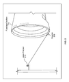
FIG. 1 is a diagram illustrating the use of laser radar for providing circumferential measurements. Referring toFIG. 1 , there is shown alaser radar 100 andfuselage sections 110. - The
laser radar 100 may be utilized to perform measurements, in particular circumferential measurements of curvilinear shaped structures, which may comprise barrel like structures, such as thefuselage sections 110 for example. In this regard, thelaser radar 100 may be a computer-aided portable device, which may be used to measure surfaces without requiring physical targets other than the structure whose surface is being measured. In particular, thelaser radar 100 may operate by emitting laser beams towards the surface of the structure, and may then perform measurement of the surface in radar-like manner, that is based on processing of signal reflections off the surface that are received back by the laser radar. In other words, thelaser radar 100 may perform circumferential measurements based on a plurality of natural surface points, by calculating the horizontal and/or vertical angles of what thelaser radar 100 is pointing at and determining the range based on the reflection of the laser off the surface, which also require accounting for variations in the reflection profile as a result of the topology of the surface itself. In this manner, thelaser radar 100 may be used to scan circumferential rows of data, wherein each row corresponds to different distance or depth from the edge (rim) of the structure. For example, a first row may correspond to the rim itself, and each successive row thereafter may correspond to a fixed distance increment from the previous row in away from the rim direction. In this regard, thelaser radar 100 may be moved forward or aft relative to the barrel-like structure, to measure points that are different depths or levels relative to the edge (rim) of the structure. Alternatively, thelaser radar 100 may comprise a moving mechanism that may enable adjusting the scanning angle-e.g., by adjusting the angle to the laser transmitter/receiver component(s). In this regard, thelaser radar 100 may be moved forward or aft physically to measure points at different depths from the edge of the structure. Nonetheless, more commonly measurements using laser radars, such as thelaser radar 100, may obviate the need for physical movement of the laser radar itself by incorporating other means, such as software applications, to enable configuring the laser radar components to measure at different depths or rows using theoretical points as the defining point to measure. - The use of
laser radar 100 in performing circumferential measurement, however, has some disadvantages. For one, laser radars are typically expensive equipment. Also, performing circumferential measurements usinglaser radar 100 may be time consuming. In this regard, determining the range for each measured point requires a significant amount of time (e.g., few seconds) as a result of the need to process the reflection, to account for any variation caused by the topology of the surface itself for example. Therefore, in order to measure a data row for particular surface, thelaser radar 100 may require substantial time to complete the measurement since it has to measure a large number of points (e.g., typically a few hundred points for a fuselage section), and reducing the number of measured points, to reduce the measurement time, may be undesirable since doing so may adversely affect the reliability of the measurement-i.e., the less measurement points are used the less reliable the measurement may be. Furthermore, use of laser radars for measurements, in particular circumferential measurements, has some inherent limitations. For example, the use of laser radars typically limits the measurements to internal surfaces-that is because thelaser radar 100 can only provide measurements based on reflections off various points from the same point of reference, thelaser radar 100 must be positioned and/or moved along axels that run through the interior of the structure (e.g., fuselage section). Another limitation of the laser radar is due to the angle of incidence to the surface being measured. In this regard, with radar based mechanisms, the best and most accurate surface measurement would be for the laser beam to be normal or perpendicular to the surface. As the laser beam starts to deviate from the normal condition, however, the measurement uncertainty can increase. Thus if measuring an external barrel-like shape the laser to surface normal condition would change with radial shape of the barrel and the current location of the laser radar system. To accommodate this condition thelaser radar 100 would need to be physically moved to another location to provide a better normal condition for the laser beam to continue to measure more surface points. Such need to continually move the laser radar (physically) for external surface points measurements may be a primary cause for the increased time to collect data. -
FIG. 2 is a diagram illustrating use of a circumferential laser crawler with a laser tracker, in accordance with an advantageous embodiment of the invention. Referring toFIG. 2 , there is shown thefuselage section 110, acrawler 200, and alaser tracker 210. - The
laser tracker 210 may be a computer-aided portable device used to calculate surface related measurement. In this regard, thelaser tracker 210 may be similar to thelaser radar 100 in that it may determine surface measurement based on reflection of signals, such as laser emitted by thelaser tracker 210 itself. Unlike thelaser radar 100, however, thelaser tracker 210 may perform its calculations, to generate or obtain the surface measurement for example, by tracking the reflection of its signal of a particular physical target that is different from the structure whose surface is being measured. For example, thelaser tracker 210 may be configured to lock its laser beam on a particular reflector, which may be suited to reflect a laser beam, having the characteristics of the beam emitted by thelaser tracker 210, back to source of the beam. In this regard, the laser beam emitted by thelaser tracker 210 reflects off a reflector, and thelaser tracker 210 calculates the range based on the time that laser beam may require to travel to that reflector and come back to thelaser tracker 210. Thelaser tracker 210 may remain locked on the reflector. In other words, the measurement by thelaser tracker 210 may be performed by simply locking on the reflector, and then following the reflector's movement, such as along the edge of a curvilinear shaped structure like thefuselage section 110 for example, thus enabling calculation of a row of circumferential data by having the reflector complete a turn on the edge. - The
crawler 200 may be a portable automated motorized device which may be operable to move a physical target, such as a laser reflector, in a controlled manner to assist thelaser tracker 210 in performing surface measurement. In this regard, thecrawler 200 may be configured to maintain the laser reflector in a particular position, and may enable moving the reflector in that position along the edge of an structure, such as thefuselage section 110, to enable thelaser tracker 210 to generate and/or obtain surface measurement (e.g., circumferential measurement). - The
crawler 200 may comprise a plurality of components performing various operations in support of intended functions of thecrawler 200. For example, thecrawler 200 may comprise a reflector holder component, for providing the necessary function pertaining to the reflector-e.g., holding the reflector at particular position, maintaining the reflector in contact with the surface, etc. Thecrawler 200 may also comprise a movement component which may enable thecrawler 200 to move along an edge of a structure, including curvilinear shaped structures such as thefuselage section 110. In this regard, the movement component of thecrawler 200 may be configured to enable thecrawler 200 to run on the inside or the outside of thefuselage section 110 or other similar barrel-shaped structures. To that end, thecrawler 200 may comprise a clamping component and/or functions to ensure that thecrawler 200 grips securely and/or tightly on the traversed edge, and/or that the crawler moved in consistent manner-that is ensuring that the reflector in maintained in the preselected position relative to the edge. - The
crawler 200 may also comprise a controller component for controlling various operations and/or components of thecrawler 200. In this regard, the controller component may comprise a programmable circuitry providing control signals to at least some of the components of thecrawler 200, to enable configuring these components to perform various operations in support of the functions of thecrawler 200. For example, the controller component may control operations of the movement component of thecrawler 200. - In an embodiment of the invention, the
crawler 200 may be configured to receive and/or transmit information, such as by incorporating a communication component for providing and/or handling communications to and/or from thecrawler 200. In this regard, thecrawler 200 may receive, for example, user input, which may be used in controlling and/or adjusting various operations or functions of thecrawler 200. For example, the user input may comprise movement related commands, such as "start" or "stop" and/or other similar commands. Thecrawler 200 may also be operable to transmit status information, such as information relating to various components or functions of the crawler. The status information may be transmitted to thelaser tracker 210 and/or to other devices that may be utilized by users (e.g., computer). The reception and/or transmission may be performed wirelessly, using one or more appropriate technologies. For example, communications may be via infra-red (IR) signals, Bluetooth signals, and/or WiFi signals. The invention is not limited, however, to any particular communication technology. - The
laser tracker 210 may be used in conjunction with thecrawler 200 in performing circumferential measurement. In this regard, thelaser tracker 210 may generate and/or obtain circumferential measurement based on range calculations using laser beams that are directed to the reflector of the crawler, by utilizing timing and/or distance information derived based on reception of reflections back from the laser reflector of the crawler. The reflector of thecrawler 200 may be initially set at a particular position, relative to the edge of thefuselage section 110, and thelaser tracker 210 may be locked on the reflector-that is thelaser tracker 210 may be setup to direct its laser beam at the reflector. Thecrawler 200 may then move along the edge of thefuselage section 110, with thelaser tracker 210 remaining locked on the reflector and following its movement (along with the crawler 200), and this tracking of the reflector may be utilized to enable the laser tracker to generate and/or obtain circumferential measurement for a row corresponding to the reflector position. The process may be repeated with the reflector being moved to different positions, such as by incorporating a sliding component for example which may be combined with or attached to the reflector holder component, thus enabling generating and/or obtaining circumferential measurements for different rows. - Use of the
laser tracker 210 in conjunction with thecrawler 200 to perform circumferential measurement may provide numerous advantages over other methods, such as radar metrology based techniques(e.g., when using the laser radar 100). Tracking based devices or systems, such as thelaser tracker 210 may be significantly cheaper compared to laser radars, and therefore laser tracking based methods may be significantly cheaper than radar based methods, even with the added cost of other devices whose use may be required in tracking based operations-e.g., thecrawler 200. In addition, use of laser tracking techniques may result in substantial reduction in time because tracking based range calculations may be many times faster than radar based calculations, since laser trackers utilized reflections from an optimal and already locked on target (e.g., the laser reflector of the crawler 200), thus obviating the need for the complex processing typically required with radar based operations. Also, unlike radar based techniques, which are typically limited to providing circumferential measurements of internal surfaces of barrel-like (or similarly shaped) structures, tracking based measurements in accordance with the present invention may enable generating and/or obtaining circumferential measurements for internal and external surfaces of a structure like as thefuselage section 110. For example, circumferential measurements for external surfaces may be obtained by setting thecrawler 200 to move with the laser reflector being positioned directly on (or relative to) the external surface. In this regard, to ensure that the laser reflector remain seen by thelaser tracker 210, the laser reflector may be positioned slightly off the external surface, using a predetermined offset from the surface for example, to ensure that the laser reflector is not blocked by the structure at any point during the traversal of the edge, with thelaser tracker 210 being configured to account for that offset when generating the measurement for the external surface. To enable and/or accommodate for positioning the laser reflector off of the measured surface-i.e., without direct contact between the laser reflector and the measured surface-a physical component, such as holder mechanism may be incorporated into thecrawler 200, which may ensure that the laser reflector may be maintained at particular and constant offset as thecrawler 200 traversed the measured surface. Furthermore, to guard against errors resulting for such positioning offset, the measurement calculations may be configured to account for that offset. For example, thelaser tracker 210 may be informed of the positioning offset between the laser reflector and the measured surface, being applied via the laser reflector holding component, and thelaser tracker 210 may then incorporate and/or account for that offset when calculating the circumferential measurements. - The tracking based approach may also result in enhanced reliability compared to radar based techniques. The use of the
crawler 200 to move the laser reflector that thelaser tracker 210 is locked on, along the edge of the structure being measured, may enable increasing the number of measurement points read when obtaining circumferential measurement for a particular row. In this regard, because the added complexity required for processing unpredictable signal reflections, laser radar based methods may only allow measuring limited number of points-e.g., every one inch or half inch, to minimize the amount of time it takes to obtain circumferential measurement for a row. On the other hand, because handling the signal reflections and performing the calculations based thereon (and thus the measurements) are done much faster with laser trackers, the use of the combination of thelaser tracker 210 and thecrawler 200 may enable capturing measurement data at much higher rate, in time and/or distance. Thelaser tracker 210 may, for example, obtain measurement related readings in as small as a fraction of a second and/or at very small spatial intervals (e.g., every tenth). In other words, because thelaser tracker 210 remains locked on the laser reflector attached to thecrawler 200 as it moves along the edge, data may be collected at any rate, thus allowing for collection of substantial amount of data, much more than typically possible with radar based techniques, while still being able to do so in timely manner (e.g., even in less time). One other advantage is the ability to control and/or adjust the measurement operations by adjusting thecrawler 200 and/or its movement using the communication link available with thecrawler 200, which may allow for very flexible data collections and/or measurement. -
FIG. 3 is a diagram illustrating a circumferential laser crawler, in accordance with an advantageous embodiment of the invention. Referring toFIG. 3 , there is shown thecrawler 200 ofFIG. 2 . Also shown inFIG. 3 is auser controller 370. - The
crawler 200 may comprise a plurality of components that may perform and/or support various functions of thecrawler 200. Thecrawler 200 may comprise, for example, acontroller box 300, a plurality ofwheels 310, alaser reflector 320, atraverse bar 330, one ormore motors 340, one ormore clamping assemblies 350, and a battery/holder assembly 360. - The
controller box 300 may comprise suitable logic, circuitry, interfaces, and/or code for controlling operations and/or functions of thecrawler 200, and/or components thereof. To that end, thecontroller box 300 may utilize internal connects to various components of thecrawler 200, to enable interactions between these components and thecontroller box 300. Thecontroller box 300 may comprise aprocessor 302, which may be operable to control and/or manage operations of thecrawler 200. In this regard, theprocessor 302 may be operable to configure and/or control operations of various components and/or subsystems of thecrawler 200, by utilizing control signals for example. The invention is not limited to any particular type of processors, and various types of processors may be used, including general purpose processors, microprocessors, and/or ASICs. Thecontroller box 300 may also comprise acommunication module 304, which may enable transmission and/or reception of data. In this regard, thecommunication module 304 may support wireless communications, in accordance with one or more wireless interfaces, technologies, and/or standards. For example, thecommunication module 304 may be configured to transmit and/or receive infra-red (IR) signals, Bluetooth signals, WiFi signals, and/or other similar type of signals. - The
wheels 310 may be used to enable moving thecrawler 200. In this regard, the motors 340 (shown inFIG. 4 ) may be utilized to provide automated motorized movement of thecrawler 200, by driving at least some of moving components of thecrawler 200, such as , such as one or more of thewheels 310. Themotors 340 may be configured to provide continuous and/or constant rotation of thewheels 310. Movement of thecrawler 200 may also comprise use of, beside thewheels 310, additional wheels and/or rollers, which may be in contact with other surfaces or edges-that is beside the surface on which thewheels 310 are running. In this regard, the additional wheels and/or rollers may support controlling the movement of thecrawler 200, ensuring that thecrawler 200 would remain tightly secured to the surfaces and/or edge during its movement. This enhanced quality of the movement of thecrawler 200 may result in enhancing the reliability of the measurement performed based on that movement. The additional wheels and/or rollers need not be motorized-i.e., may not be driven by themotors 340. The invention, however, is not so limited and themotors 340 may be utilized to drive all moving components of thecrawler 200. - To further enhance the movement of the
crawler 200, a clamping mechanism may be utilized to further ensure that the various moving parts of thecrawler 200 remain in contact with the surfaces and/or edges on which they run, and/or that thecrawler 200 continually run as tightly as possible on the edge of the measured structure. For example, clampingassemblies 350 may be utilized to connect thewheels 310 to corresponding wheels running on the opposite surface of thefuselage section 110, and to push these wheels tightly into thefuselage section 110, thus pushing both of these wheels firmly against the surfaces on which they are running. Various mechanisms may be utilized to proving the clamping function. For example, a torsion spring, clam shell design may be utilized, in which springs 352 may be utilized to ensure that the wheels that are pressed into the surfaces on which they run, by pulling the different sets of wheels into each other. - The movement of the
crawler 200 may be further enhanced by other means, to further ensure that thecrawler 200 remain tightly secured to the surfaces and/or edge during its movement, and/to ensure that the position of thelaser reflector 320 is maintained throughout the movement of thecrawler 200. For example, some of the wheels and/or rollers may be grouped into separate sets, with these sets being configured to provide for rotational and/or lateral flexibility therebetween-i.e., the sets being able to be offset laterally (relative to the edge, thus conforming to any slanting in the edge) and/or rotationally (to better conform to the traversed surface while keeping the wheels and/or rollers in contact with the surface). This may be achieved by incorporating a tracking component for providing such lateral and/or rotational offsetting between the sets of wheels and/or rollers. These features are described in more details in one or more of the following drawings. - The
laser reflector 320 may be operable to reflect laser beams, such as those emitted by thelaser tracker 210. In this regard, thelaser reflector 320 may be configured to optimally reflect signals generated and/or emitted by thelaser tracker 210. A holding assembly may be utilized to hold thelaser reflector 320. In this regard, the holding assembly of thelaser reflector 320 may be utilized to attach thelaser reflector 320 to thecrawler 200, and may also be utilized to ensure that thelaser reflector 320 remains in contact with the measured surface. Various mechanisms may be utilized to ensure that thelaser reflector 320 may remain in contact with the traversed surface. For example, thelaser reflector 320 may incorporate a spring-loaded design, in which the torsion springs may be utilized to push thelaser reflector 320 tightly against the surface of the traversed surface (e.g., internal or external surfaces of the fuselage section 110). In some instances, thelaser reflector 320 may be moved relative to the edge of the structure, to enable measuring different rows of data. This may be achieved by use of thetraverse bar 330, which may enable sliding the holding assembly of thelaser reflector 320 away and/or towards the edge. These features are explained in more detail in one or more of the following drawings. - The battery/
holder assembly 360 may comprise one or more batteries for providing power to various components of thecrawler 200, such as via one ormore power cables 362, thus enabling operations thereof. In this regard, the battery/holder assembly 360 may comprise any type of battery that may be suitable to provide power to thecrawler 200, and/or any components thereof. While thecrawler 200 is described as having a battery based power supply, the invention is not so limited. Accordingly, any type of power supply that may be suitable for providing power to thecrawler 200 may be utilized. In this regard, a power supply may be deemed suitable based on various considerations, including power related and non-power related factors. For example, power supply may be evaluated to determine if it may provide sufficient and/or suitable voltage or wattage, but may also be evaluated to determine whether it is of suitable size and/or weight-e.g., the power supply typically should not be too bulky or heavy as since excessive weight or size may adversely affect the movement of thecrawler 200. - The
user controller 370 may comprise suitable logic, circuitry, interfaces, and/or code for enabling users to interact with thecrawler 200. In this regard, theuser controller 370 may be utilized, for example, to send user input to thecrawler 200, and/or to obtain information from thecrawler 200. The user input may comprise, for example, commands pertaining to various functions or operations of thecrawler 200. For example, the commands may comprise movement related commands, such as "start," "pause," and "stop;" and/or speed related commands (i.e., specifying particular speed for the movement of the crawler 200). The interactions between theuser controller 370 and thecrawler 200 may be performed via wireless communication. For example, theuser controller 370 may be configured to transmit commands via infra-red (IR) signals, Bluetooth signals, WiFi signals, and/or other similar type of signals. -
FIG. 4 is a diagram illustrating various moving and positioning components of a circumferential laser crawler, in accordance with an advantageous embodiment of the invention. Referring toFIG. 4 , there is shown thecrawler 200. - The
crawler 200 may incorporate, in addition thewheels 310 described inFIG. 3 , additional wheels and/or rollers that may ride along surfaces and/or edges other than the surfaces on which thewheels 310 are running, to enhance the movement of thecrawler 200. For example, in addition to thetop wheels 310, thecrawler 200 may incorporatebottom wheels 420, which may move on the surface opposite of the surface on whichwheels 310 are running; and/orvertical rollers 410, which may be contact with, and run on the edge of the structure whose circumferential data is being measured. It should be understood that the use of the terms "top" "bottom" and "vertical" is intended for explanatory and demonstrative purposes only, and that these terms do not impose spatial limitations with respect to the corresponding items. In other words, the "top" wheels are only top wheels in the sense that they are running on the top surface in the perspective of thecrawler 200 shown in the drawings. Thevertical rollers 410 may be utilized to ensure that thecrawler 200 indexed (i.e., in tight contact) with the edge, and running on it. The use of bottom wheels, in addition to the top wheels, may make movement of the crawler easier. - To further enhance the movement of the
crawler 200, a clamping mechanism may be utilized to further ensure that the various moving parts of thecrawler 200 remain in contact with the surfaces and/or edges on which they run, and/or that thecrawler 200 continually run as tightly as possible on the edge of the measured structure. For example, spring-torsion, clamshell clamping assemblies 350 may be utilized to connect the assemblies holding thetop wheels 310 and thebottom wheels 420, thus pushing both of these wheels firmly against the surfaces on which they are running. - Another mechanism that may incorporated into the movement component of the
crawler 200, to further ensure that thecrawler 200 runs tightly along theedge 430 of the structure, is angling the wheels. In this regard, thetop wheels 310 and/orbottom wheels 420 may be configured to move at anangled path 450, whereby the wheels may run slanted rather than straight, driving into the structure along the direction ofmovement 440 of the crawler 200 (as shown in in the top prospective view inFIG. 4 ), to further ensure that thecrawler 200 remains tightly secured to theedge 430 of the structure as it moves along theedge 430. The use ofvertical rollers 410 may assist the angled movement of thetop wheels 310 and/orbottom wheels 410, by enabling thecrawler 200 to run smoothly along theedge 430 while the angled movement of the wheels drives the crawler into the structure (and thus the edge 430). -
FIG. 5 is a diagram illustrating an articulated assembly of a circumferential laser crawler for enabling conforming to surfaces and/or for keeping moving components in contact with the surfaces, in accordance with an advantageous embodiment of the invention. Referring toFIG. 5 , there is shown thecrawler 200. - Another feature that may be incorporated into the
crawler 200, to further ensure that thecrawler 200 securely and tightly traverses curvilinear edges, including edges that may be uneven, is the grouping the moving parts (wheels and/or rollers) of thecrawler 200 into separate sets. For example, some of the wheels of thecrawler 200 may be grouped into separate assemblies, shown inFIG. 5 as afirst set 520A and asecond set 520B, with these sets being configured to allow for rotational and/or lateral adjustments relative to one another, to ensure that thecrawler 200 may better conform to the edges and/or surfaces traversed. Thefirst set 520A and thesecond set 520B may comprise any combination of moving parts of thecrawler 200. For example, thefirst set 520A and thesecond set 520B may comprise only groups oftop wheels 310, only groups ofbottom wheels 420, and/or groups of bothtop wheels 310 andbottom wheels 420, and thus may also include a portion of the clamping component connecting the top and bottom wheels, and/or vertical roller(s). - The
first set 520A and thesecond set 520B may be configured to incorporate an articulated assembly to allow these sets to rotate relative to each other, so that both sets (520A and 520B) may remain in contact, even when traversing a section with uneven surface, ensuring that most (or all) of the wheels remain in contact with the surface. In other words, incorporating the articulated assembly may enable thefirst set 520A and thesecond set 520B to independently tilt (right or left along the direction of movement 440), thus conforming to the surface areas that these sets are in contact with at any given point. This may be achieved, for example, by incorporating a single axle rod/bolt assembly 510 to connect thefirst set 520A and thesecond set 520B, thus allowing each to rotate, relative to each other, along an axle that is parallel to the direction of movement of thecrawler 200. While thecrawler 200 is shown with two sets (of wheels), the invention need not be so limited. Accordingly, different number of sets may be utilized, and/or with rotating assemblies being utilized to connect all or some of these sets as deemed optimal to achieve the best surface conformity characteristic for thecrawler 200. -
FIG. 6 is a diagram illustrating a tracking adjustment component of a circumferential laser crawler for enabling variable lateral adjustment of moving parts relative to edges, in accordance with an advantageous embodiment of the invention. Referring toFIG. 6 , there is shown thecrawler 200. Also, shown inFIG. 6 are thefirst set 520A and thesecond set 520B, which may be utilized when thecrawler 200 may incorporated grouped based configuration of movement components. - The
first set 520A and thesecond set 520B may be configured to incorporate a tracking adjustment, to allow these sets to move laterally relative to one another, so that both sets may independently try to remain in contact with the traversed edge, even when the edge is uneven-e.g., when the edge is slanted or angled. In this regard, allowing thefirst set 520A and thesecond set 520B to offset laterally may ensure that these sets may independently remain as tightly secured to the edge as possible, whereas not allowing such lateral offsetting may otherwise cause one of these sets to move away or dislodge from the edge. Therefore, incorporating tracking adjustment may enable thefirst set 520A and thesecond set 520B to independently remain in contact with to the edge even when the edge may not be straight. This may be achieved, for example, by incorporating a tracking adjustment slot 600 to enable any connection assembly connecting the two sets to move laterally. For example, the single axle rod/bolt assembly 510 utilized to connect thefirst set 520A and thesecond set 520B (allowing for rotational adjustment between the set) may be combined with the tracking adjustment slot 600, to also allow lateral offsetting, by enabling the axle rod/bolt assembly 510 to move within the tracking adjustment slot 600, thus allowing the sets to offset laterally such that the wheels in these sets may increase or decrease the amount the wheels drive away from the edge. -
FIG. 7 is a diagram illustrating a reflector component of a circumferential laser crawler for enabling adjustment and locking of reflector relative to surfaces, in accordance with an advantageous embodiment of the invention. Referring toFIG. 7 , there is shown thelaser reflector 320 of thecrawler 200. - The
laser reflector 320 may be attached to thecrawler 200 to enable utilizing thelaser tracker 210 in generating and/or obtaining measurement data pertaining to the structure whose edge is traversed by thecrawler 200. A holding assembly may be utilized to hold thelaser reflector 320, attach it to thecrawler 200, and/or to maintain position of thelaser reflector 320 relative to the surface of the structured being measured. In this regard, thereflector holder 710 may be utilized to hold thelaser reflector 320 in position while thecrawler 200 is moving. Because thelaser reflector 320 may not be exactly on the surface being measured, thelaser tracker 210 may be configured to account for any separation between the surface and the center oflaser reflector 320 during the calculation performed in the course of obtaining and/or generating the measurement data. Various designs and/or mechanisms may be incorporated into thereflector holder 710 to ensure that thelaser reflector 320 may remain in contact with the traversed surface, or maintain its position (e.g., when thelaser reflector 320 is positioned off the surface, such as during measurements of external surfaces). For example, thelaser reflector 320 may incorporate a spring-loaded design, in which thetorsion spring 730 and theset screw lock 720 may be utilized to ensure that thelaser reflector 320 remain in positions by use of spring loading force being applied against the locking mechanism. Thetorsion spring 730 may be utilized to apply torsion force on thereflector holder 710 to maintain contact (the holder and thus the reflector itself) with the surface. Theset screw lock 720 may be utilized to lock the holding assembly in position. In some instances, theset screw lock 720 may be utilized to lock the holding assembly such thatlaser reflector 320 may be offset away from surface. This may be done, for example, when the crawler is setup to move along the edge such that the top part of the crawler corresponds to the outer surface of the structure, thus enabling generation of measurement data for the outside surface. In this regard, holding thelaser reflector 320 at a distance from the surface may ensure that thelaser reflector 320 remains seen by thelaser tracker 210 as the crawler move along the edge of the structure (e.g., fuselage section 110). In such instances, thelaser tracker 210 may be configured to account for that added distance from the surface during calculation performed in the course of obtaining and/or generating the measurement data. - The
laser reflector 320 may be moved to different positions, on the surface of the structure (e.g., fuselage section 110) being measured, relative to the edge of the structure. Repositioning thelaser reflector 320 may enable generating and/or obtaining plurality of circumferential rows of data. For example, the holding assembly-which may comprise thereflector holder 710, theset screw lock 720, and the torsion spring 730-may be configured to slide along thetraverse bar 330 such that thelaser reflector 320 may be positioned at different distances from the edge. -
FIG. 8 is a diagram illustrating a reflector traversing component of a circumferential laser crawler for enabling adjustment of positioning of reflector relative to edges, in accordance with an advantageous embodiment of the invention. Referring toFIG. 8 , there is shown thetraverse bar 330 of thecrawler 200. - The
traverse bar 330 may be utilized to enable sliding the holding assembly, which holds thelaser reflector 320, towards and/or away from the edge of the structure being measured, to enable generating plurality of circumferential rows of data. For example, thecrawler 200 may initially be setup with thelaser reflector 320 positioned at thenear edge position 800, which may correspond to the closest position to the edge. After thecrawler 200 completes a movement around the edge of the structure being measure, thelaser reflector 320 may be reposition to each ofmultiple positions 810, up to the far edge position 820, which may correspond to the furthest position from the edge. The repositioning may be done by moving the holding assembly along thetraverse bar 330. At each position thecrawler 200 may complete a move along the edge, to generate corresponding circumferential measurement data, before being repositioned to the next position. -
FIG. 9 is a flow chart that illustrates exemplary operations performed by a circumferential laser crawler during measurement, in accordance with an advantageous embodiment of the invention. Referring toFIG. 9 , there is shown aflow chart 900 comprising a plurality of steps. - In
step 902, a laser reflector may be positioned in a particular position relative to edge of a structure being measured. In this regard, the laser reflector may be attached to an automated motorized device (e.g., thelaser reflector 320 of the crawler 200). Instep 904, the crawler may move along the edge of the structure while circumferential coordinate data is being acquired during movement of the crawler, such as by use of laser tracker metrology system (e.g., laser tracker 210). Instep 906, the movement of the crawler, and acquiring of circumferential data based thereon, may continue until a complete circumferential row of data is obtained and/or generated. Instep 908, it may be determined whether additional circumferential rows of data are needed. If no additional circumferential row of data is needed, the plurality of steps may terminate. - Returning to step 908, if additional circumferential row of data is needed, the plurality of steps may proceed to step 910. In
step 910, the laser reflector may be repositioned into another position relative to the edge. For example, after obtaining circumferential row of data corresponding to thenear edge position 800, thelaser reflector 320 may be repositions in one or more themultiple positions 810 and/or the far edge position 820. The plurality of step may then return to step 904, to enable obtaining and/or generating circumferential row of data corresponding to the new position. - Other embodiments of the invention may provide a non-transitory computer readable medium and/or storage medium, and/or a non-transitory machine readable medium and/or storage medium, having stored thereon, a machine code and/or a computer program having at least one code section executable by a machine and/or a computer, thereby causing the machine and/or computer to perform the steps as described herein for circumferential laser crawler.
- Accordingly, the present invention may be realized in hardware, software, or a combination of hardware and software. The present invention may be realized in a centralized fashion in at least one computer system, or in a distributed fashion where different elements are spread across several interconnected computer systems. Any kind of computer system or other system adapted for carrying out the methods described herein is suited. A typical combination of hardware and software may be a general-purpose computer system with a computer program that, when being loaded and executed, controls the computer system such that it carries out the methods described herein.
- The present invention may also be embedded in a computer program product, which comprises all the features enabling the implementation of the methods described herein, and which when loaded in a computer system is able to carry out these methods. Computer program in the present context means any expression, in any language, code or notation, of a set of instructions intended to cause a system having an information processing capability to perform a particular function either directly or after either or both of the following: a) conversion to another language, code or notation; b) reproduction in a different material form.
- While the present invention has been described with reference to certain embodiments, it will be understood by those skilled in the art that various changes may be made and equivalents may be substituted without departing from the scope of the present invention. In addition, many modifications may be made to adapt a particular situation or material to the teachings of the present invention without departing from its scope. Therefore, it is intended that the present invention not be limited to the particular embodiment disclosed, but that the present invention will include all embodiments falling within the scope of the appended claims.
Claims (15)
- An apparatus, comprising:an automated motorized device (200) operable to run along a curvilinear shaped edge (430) of a structure, the automated motorized device (200) comprising:a movement component operable to move the automated motorized device (200) along the curvilinear shaped edge (430) of the structure; anda reflector (320) that is operable to reflect signals back to a source of the signals.
- The apparatus of claim 1, wherein the reflector (320) is spring loaded.
- The apparatus of claim 1 or 2, wherein the automated motorized device (200) comprises a sliding component for enabling movement of the reflector (320).
- The apparatus of any of claim 1 to 3, wherein the automated motorized device (200) comprises a clamping component (350) for tightly securing the automated motorized device (200) to the edge (430) during movement of the automated motorized device (200) along the edge (430).
- The apparatus of any of claim 1 to 4, wherein the movement component comprises a plurality of wheels (310) and/or rollers (410), said wheels (310) comprising one or more drive wheels that are driven by one or more motors (340) in said automated motorized device (200).
- The apparatus of claim 5, wherein the plurality of wheels (310) and/or rollers (410) comprises one or more drive wheels that are driven by one or more motors (340) in said automated motorized device (200).
- The apparatus of claim 5 or 6, wherein the plurality of wheels (310) and/or rollers (410) comprises one or more vertical rollers riding against the edge (430) of the structure.
- The apparatus of any of claims 5 to 7, wherein the plurality of wheels (310) and/or rollers (410) comprises a first one or more wheels running on a first surface of the structure and a second one or more wheels running on a second surface of the structure that is opposite of said first surface, and each of the first one or more wheels and the second one or more wheels are pushed tightly into the surface on which they are running.
- The apparatus of any of claims 5 to 8, wherein the plurality of wheels (310) and/or rollers (410) comprises one or more wheels that drive at an angle relative to the edge and into the structure.
- The apparatus of any of claims 5 to 9, wherein the automated motorized device (200) comprises a tracking component for enabling at least some of the wheels and/or rollers to move independent of other wheels and/or rollers.
- The apparatus of any of claims 1 to 10, wherein the automated motorized device (200) comprises:a controller (300) for controlling operations of at least some of components of the automated motorized device (200); and a communication component (304) for receiving and/or transmitting data, said data comprising user input, feedback and/or status information.
- A method, comprising:positioning a reflector (320) of an automated motorized device (200) in a particular position relative to a curvilinear edge (430) of a structure; andobtaining circumferential row of data at the particular position by:moving the automated motorized device (200) along the curvilinear edge (430);acquiring circumferential coordinate data during movement of the automated motorized device (200) using a laser tracker (210); andcontinuing to move the automated motorized device (200) and acquire circumferential data until a complete circumferential row of data is obtained.
- The method of claim 12, comprising acquiring the circumferential coordinate data based on:transmitting of signals from the laser tracker (210), andreceiving by the laser tracker (210) signal reflections off of the reflector (320).
- The method of claim 12 or 13, comprising obtaining a plurality of additional circumferential rows of data by:repositioning the reflector (320) of the automated motorized device (200) in a plurality of other positions, andobtaining a circumferential row of data at each of the plurality of other positions.
- The method of any of claims 12 to 14, comprising communicating with the automated motorized device (200) to send user input to the automated motorized device (200) and/or to obtain information from the automated motorized device (200).
Applications Claiming Priority (1)
| Application Number | Priority Date | Filing Date | Title |
|---|---|---|---|
| US13/441,239 US9030673B2 (en) | 2012-04-06 | 2012-04-06 | Circumferential laser crawler |
Publications (3)
| Publication Number | Publication Date |
|---|---|
| EP2648016A2 true EP2648016A2 (en) | 2013-10-09 |
| EP2648016A3 EP2648016A3 (en) | 2014-06-11 |
| EP2648016B1 EP2648016B1 (en) | 2017-03-15 |
Family
ID=48288759
Family Applications (1)
| Application Number | Title | Priority Date | Filing Date |
|---|---|---|---|
| EP13161740.9A Active EP2648016B1 (en) | 2012-04-06 | 2013-03-28 | Circumferential laser crawler |
Country Status (6)
| Country | Link |
|---|---|
| US (1) | US9030673B2 (en) |
| EP (1) | EP2648016B1 (en) |
| JP (1) | JP6282404B2 (en) |
| CN (1) | CN103363908B (en) |
| BR (1) | BR102013008144B1 (en) |
| CA (1) | CA2807610C (en) |
Cited By (2)
| Publication number | Priority date | Publication date | Assignee | Title |
|---|---|---|---|---|
| EP3048416A1 (en) * | 2015-01-21 | 2016-07-27 | The Boeing Company | Systems, methods, and apparatus for automated predictive shimming for large structures |
| WO2017097944A1 (en) * | 2015-12-10 | 2017-06-15 | Sms Group Gmbh | Method and device for measuring a contour of a body or for checking the position thereof about an axis of rotation |
Families Citing this family (7)
| Publication number | Priority date | Publication date | Assignee | Title |
|---|---|---|---|---|
| US9505101B1 (en) | 2015-06-24 | 2016-11-29 | The Boeing Company | Automated sanding system and method |
| EP4303622A3 (en) * | 2016-11-10 | 2024-04-03 | Leica Geosystems Ag | Laser scanner |
| US10633117B2 (en) * | 2017-10-03 | 2020-04-28 | The Boeing Company | Alignment systems and methods for moving fuselage structures of an aerospace vehicle into assembly alignment |
| CN108190044B (en) * | 2017-12-05 | 2020-07-28 | 北京星航机电装备有限公司 | Method for assembling all-axial thermal protection component for aircraft assembly |
| CN112665507A (en) * | 2021-01-13 | 2021-04-16 | 郭红霞 | Detection method of power cable detection system |
| CN113375605B (en) * | 2021-04-22 | 2022-07-15 | 首钢京唐钢铁联合有限责任公司 | Spatial positioning method for supporting wheel of circular cooler |
| CN117961393B (en) * | 2024-04-01 | 2024-06-18 | 江苏威士智能装备有限公司 | Automatic welding device and working method |
Family Cites Families (15)
| Publication number | Priority date | Publication date | Assignee | Title |
|---|---|---|---|---|
| JP3153652B2 (en) * | 1992-10-09 | 2001-04-09 | 日立機電工業株式会社 | Moving target for rail measuring device |
| US5487440A (en) | 1993-05-18 | 1996-01-30 | Seemann; Henry R. | Robotic apparatus |
| CN2321502Y (en) * | 1998-04-02 | 1999-06-02 | 上海游艺机工程有限公司 | Hanging type chute |
| JP2000162307A (en) | 1998-11-30 | 2000-06-16 | Mitsubishi Heavy Ind Ltd | Laser tracking apparatus for locating position of reactor vessel-inspecting robot |
| US7155307B2 (en) * | 2001-09-09 | 2006-12-26 | Seemann Henry R | Surface adhering tool carrying robot |
| US6940212B2 (en) * | 2002-02-08 | 2005-09-06 | Metscan Technologies, Llc (A Georgia Limited Liability Corporation) | Non-fluid acoustic coupling |
| US7230689B2 (en) | 2002-08-26 | 2007-06-12 | Lau Kam C | Multi-dimensional measuring system |
| JP3966335B2 (en) * | 2005-02-17 | 2007-08-29 | 東日本旅客鉄道株式会社 | Trajectory inspection method and trajectory inspection kit |
| CN201026879Y (en) * | 2007-03-10 | 2008-02-27 | 东营市华方船体研制有限责任公司 | Cable car sliding device |
| US7743660B2 (en) | 2007-06-15 | 2010-06-29 | The Boeing Company | System and method for automated inspection of large-scale part |
| US8453576B2 (en) * | 2007-08-16 | 2013-06-04 | Vekoma Rides Engineering B.V. | Rollercoaster amusement device |
| US7978322B2 (en) * | 2009-02-06 | 2011-07-12 | The Boeing Company | Calibrating aircraft surfaces |
| US20110087457A1 (en) * | 2009-10-09 | 2011-04-14 | Furmanite Worldwide, Inc. | Surface measurement, selection, and machining |
| JP2012237661A (en) * | 2011-05-12 | 2012-12-06 | Ntn Corp | Measurement auxiliary tool and diameter measuring method using the same |
| US8713998B2 (en) * | 2011-06-14 | 2014-05-06 | The Boeing Company | Autonomous non-destructive evaluation system for aircraft structures |
-
2012
- 2012-04-06 US US13/441,239 patent/US9030673B2/en active Active
-
2013
- 2013-02-28 CA CA2807610A patent/CA2807610C/en active Active
- 2013-03-28 EP EP13161740.9A patent/EP2648016B1/en active Active
- 2013-04-03 CN CN201310116434.3A patent/CN103363908B/en active Active
- 2013-04-04 BR BR102013008144-2A patent/BR102013008144B1/en active IP Right Grant
- 2013-04-05 JP JP2013079120A patent/JP6282404B2/en active Active
Non-Patent Citations (1)
| Title |
|---|
| None |
Cited By (3)
| Publication number | Priority date | Publication date | Assignee | Title |
|---|---|---|---|---|
| EP3048416A1 (en) * | 2015-01-21 | 2016-07-27 | The Boeing Company | Systems, methods, and apparatus for automated predictive shimming for large structures |
| US9599983B2 (en) | 2015-01-21 | 2017-03-21 | The Boeing Company | Systems, methods, and apparatus for automated predictive shimming for large structures |
| WO2017097944A1 (en) * | 2015-12-10 | 2017-06-15 | Sms Group Gmbh | Method and device for measuring a contour of a body or for checking the position thereof about an axis of rotation |
Also Published As
| Publication number | Publication date |
|---|---|
| CA2807610A1 (en) | 2013-10-06 |
| CN103363908A (en) | 2013-10-23 |
| CA2807610C (en) | 2020-07-07 |
| CN103363908B (en) | 2018-03-23 |
| JP2013217920A (en) | 2013-10-24 |
| US20130265588A1 (en) | 2013-10-10 |
| EP2648016B1 (en) | 2017-03-15 |
| EP2648016A3 (en) | 2014-06-11 |
| US9030673B2 (en) | 2015-05-12 |
| JP6282404B2 (en) | 2018-02-21 |
| BR102013008144A2 (en) | 2015-08-04 |
| BR102013008144B1 (en) | 2020-11-17 |
Similar Documents
| Publication | Publication Date | Title |
|---|---|---|
| CA2807610C (en) | Circumferential laser crawler | |
| EP3603372B1 (en) | Moving robot, method for controlling the same, and terminal | |
| CA2831682C (en) | Measuring system for determining 3d coordinates of an object surface | |
| US11053925B2 (en) | Cable-suspended non-destructive inspection units for rapid large-area scanning | |
| EP4325250A2 (en) | Vehicular alignment for sensor calibration | |
| EP2112468A1 (en) | Parameter detection system and control method | |
| US8596217B2 (en) | Application controller | |
| US20120158222A1 (en) | Centering above a predetermined area of a landing platform | |
| CN103809184B (en) | A kind of recognition methods of robot positioning system and its reflection unit | |
| US20200300225A1 (en) | Measuring system for measuring a surface of a rotor blade of a wind turbine | |
| WO2019157035A1 (en) | Tilt and distance profiling vehicle | |
| US11719228B2 (en) | Methods and apparatus for maintaining airfoil-shaped body using cart that follows trailing edge | |
| US7725287B2 (en) | System and method for using structured shapes to increase laser scanner accuracy | |
| CN106597470A (en) | A device and method for acquiring 3D point cloud data using a 2D laser scanner | |
| JP6820546B2 (en) | A method for adjusting a reflective member in a three-dimensional shape measuring device, a painting device, and a three-dimensional shape measuring device, and a method for supporting angle adjustment of a reflective member in a three-dimensional shape measuring device | |
| WO2024145955A9 (en) | Indoor positioning apparatus and method for narrow and long space | |
| JP2026027500A (en) | Position measuring device, system, and position measuring method | |
| JP6754518B2 (en) | Position estimation system | |
| CN117519139A (en) | Recharging method, mobile robot and storage medium | |
| US20230135740A1 (en) | Distance measurement device, and mounting orientation sensing method and mounting orientation sensing program for same | |
| JP2010186393A (en) | Tracking control device and tracking control method | |
| CN112947396A (en) | Method for compensating included angle error of reflective beacon, automatic walking equipment and storage medium | |
| CN118565431A (en) | A method for realizing intelligent millimeter-level elevation measurement based on laser technology | |
| US9075401B2 (en) | Method of correcting sensor, method of controlling motor and motor control system | |
| JP2018072206A (en) | Measuring apparatus, measuring method and measuring program |
Legal Events
| Date | Code | Title | Description |
|---|---|---|---|
| PUAI | Public reference made under article 153(3) epc to a published international application that has entered the european phase |
Free format text: ORIGINAL CODE: 0009012 |
|
| AK | Designated contracting states |
Kind code of ref document: A2 Designated state(s): AL AT BE BG CH CY CZ DE DK EE ES FI FR GB GR HR HU IE IS IT LI LT LU LV MC MK MT NL NO PL PT RO RS SE SI SK SM TR |
|
| AX | Request for extension of the european patent |
Extension state: BA ME |
|
| PUAL | Search report despatched |
Free format text: ORIGINAL CODE: 0009013 |
|
| AK | Designated contracting states |
Kind code of ref document: A3 Designated state(s): AL AT BE BG CH CY CZ DE DK EE ES FI FR GB GR HR HU IE IS IT LI LT LU LV MC MK MT NL NO PL PT RO RS SE SI SK SM TR |
|
| AX | Request for extension of the european patent |
Extension state: BA ME |
|
| RIC1 | Information provided on ipc code assigned before grant |
Ipc: G01C 15/06 20060101ALI20140505BHEP Ipc: G01S 7/481 20060101ALI20140505BHEP Ipc: G01S 17/66 20060101AFI20140505BHEP Ipc: B64F 5/00 20060101ALN20140505BHEP |
|
| 17P | Request for examination filed |
Effective date: 20141203 |
|
| RBV | Designated contracting states (corrected) |
Designated state(s): AL AT BE BG CH CY CZ DE DK EE ES FI FR GB GR HR HU IE IS IT LI LT LU LV MC MK MT NL NO PL PT RO RS SE SI SK SM TR |
|
| GRAP | Despatch of communication of intention to grant a patent |
Free format text: ORIGINAL CODE: EPIDOSNIGR1 |
|
| RIC1 | Information provided on ipc code assigned before grant |
Ipc: G01S 7/481 20060101ALI20160902BHEP Ipc: G01S 17/66 20060101AFI20160902BHEP Ipc: G01C 15/06 20060101ALI20160902BHEP Ipc: B64F 5/00 20060101ALI20160902BHEP |
|
| INTG | Intention to grant announced |
Effective date: 20160928 |
|
| GRAS | Grant fee paid |
Free format text: ORIGINAL CODE: EPIDOSNIGR3 |
|
| GRAA | (expected) grant |
Free format text: ORIGINAL CODE: 0009210 |
|
| AK | Designated contracting states |
Kind code of ref document: B1 Designated state(s): AL AT BE BG CH CY CZ DE DK EE ES FI FR GB GR HR HU IE IS IT LI LT LU LV MC MK MT NL NO PL PT RO RS SE SI SK SM TR |
|
| REG | Reference to a national code |
Ref country code: CH Ref legal event code: EP Ref country code: GB Ref legal event code: FG4D |
|
| REG | Reference to a national code |
Ref country code: FR Ref legal event code: PLFP Year of fee payment: 5 |
|
| REG | Reference to a national code |
Ref country code: IE Ref legal event code: FG4D |
|
| REG | Reference to a national code |
Ref country code: AT Ref legal event code: REF Ref document number: 876138 Country of ref document: AT Kind code of ref document: T Effective date: 20170415 |
|
| REG | Reference to a national code |
Ref country code: DE Ref legal event code: R096 Ref document number: 602013018479 Country of ref document: DE |
|
| REG | Reference to a national code |
Ref country code: NL Ref legal event code: MP Effective date: 20170315 |
|
| REG | Reference to a national code |
Ref country code: LT Ref legal event code: MG4D |
|
| PG25 | Lapsed in a contracting state [announced via postgrant information from national office to epo] |
Ref country code: HR Free format text: LAPSE BECAUSE OF FAILURE TO SUBMIT A TRANSLATION OF THE DESCRIPTION OR TO PAY THE FEE WITHIN THE PRESCRIBED TIME-LIMIT Effective date: 20170315 Ref country code: LT Free format text: LAPSE BECAUSE OF FAILURE TO SUBMIT A TRANSLATION OF THE DESCRIPTION OR TO PAY THE FEE WITHIN THE PRESCRIBED TIME-LIMIT Effective date: 20170315 Ref country code: GR Free format text: LAPSE BECAUSE OF FAILURE TO SUBMIT A TRANSLATION OF THE DESCRIPTION OR TO PAY THE FEE WITHIN THE PRESCRIBED TIME-LIMIT Effective date: 20170616 Ref country code: NO Free format text: LAPSE BECAUSE OF FAILURE TO SUBMIT A TRANSLATION OF THE DESCRIPTION OR TO PAY THE FEE WITHIN THE PRESCRIBED TIME-LIMIT Effective date: 20170615 Ref country code: FI Free format text: LAPSE BECAUSE OF FAILURE TO SUBMIT A TRANSLATION OF THE DESCRIPTION OR TO PAY THE FEE WITHIN THE PRESCRIBED TIME-LIMIT Effective date: 20170315 |
|
| REG | Reference to a national code |
Ref country code: AT Ref legal event code: MK05 Ref document number: 876138 Country of ref document: AT Kind code of ref document: T Effective date: 20170315 |
|
| PG25 | Lapsed in a contracting state [announced via postgrant information from national office to epo] |
Ref country code: BG Free format text: LAPSE BECAUSE OF FAILURE TO SUBMIT A TRANSLATION OF THE DESCRIPTION OR TO PAY THE FEE WITHIN THE PRESCRIBED TIME-LIMIT Effective date: 20170615 Ref country code: LV Free format text: LAPSE BECAUSE OF FAILURE TO SUBMIT A TRANSLATION OF THE DESCRIPTION OR TO PAY THE FEE WITHIN THE PRESCRIBED TIME-LIMIT Effective date: 20170315 Ref country code: RS Free format text: LAPSE BECAUSE OF FAILURE TO SUBMIT A TRANSLATION OF THE DESCRIPTION OR TO PAY THE FEE WITHIN THE PRESCRIBED TIME-LIMIT Effective date: 20170315 Ref country code: SE Free format text: LAPSE BECAUSE OF FAILURE TO SUBMIT A TRANSLATION OF THE DESCRIPTION OR TO PAY THE FEE WITHIN THE PRESCRIBED TIME-LIMIT Effective date: 20170315 |
|
| PG25 | Lapsed in a contracting state [announced via postgrant information from national office to epo] |
Ref country code: NL Free format text: LAPSE BECAUSE OF FAILURE TO SUBMIT A TRANSLATION OF THE DESCRIPTION OR TO PAY THE FEE WITHIN THE PRESCRIBED TIME-LIMIT Effective date: 20170315 |
|
| PG25 | Lapsed in a contracting state [announced via postgrant information from national office to epo] |
Ref country code: CZ Free format text: LAPSE BECAUSE OF FAILURE TO SUBMIT A TRANSLATION OF THE DESCRIPTION OR TO PAY THE FEE WITHIN THE PRESCRIBED TIME-LIMIT Effective date: 20170315 Ref country code: SK Free format text: LAPSE BECAUSE OF FAILURE TO SUBMIT A TRANSLATION OF THE DESCRIPTION OR TO PAY THE FEE WITHIN THE PRESCRIBED TIME-LIMIT Effective date: 20170315 Ref country code: AT Free format text: LAPSE BECAUSE OF FAILURE TO SUBMIT A TRANSLATION OF THE DESCRIPTION OR TO PAY THE FEE WITHIN THE PRESCRIBED TIME-LIMIT Effective date: 20170315 Ref country code: RO Free format text: LAPSE BECAUSE OF FAILURE TO SUBMIT A TRANSLATION OF THE DESCRIPTION OR TO PAY THE FEE WITHIN THE PRESCRIBED TIME-LIMIT Effective date: 20170315 Ref country code: EE Free format text: LAPSE BECAUSE OF FAILURE TO SUBMIT A TRANSLATION OF THE DESCRIPTION OR TO PAY THE FEE WITHIN THE PRESCRIBED TIME-LIMIT Effective date: 20170315 Ref country code: ES Free format text: LAPSE BECAUSE OF FAILURE TO SUBMIT A TRANSLATION OF THE DESCRIPTION OR TO PAY THE FEE WITHIN THE PRESCRIBED TIME-LIMIT Effective date: 20170315 |
|
| REG | Reference to a national code |
Ref country code: CH Ref legal event code: PL |
|
| PG25 | Lapsed in a contracting state [announced via postgrant information from national office to epo] |
Ref country code: IS Free format text: LAPSE BECAUSE OF FAILURE TO SUBMIT A TRANSLATION OF THE DESCRIPTION OR TO PAY THE FEE WITHIN THE PRESCRIBED TIME-LIMIT Effective date: 20170715 Ref country code: PT Free format text: LAPSE BECAUSE OF FAILURE TO SUBMIT A TRANSLATION OF THE DESCRIPTION OR TO PAY THE FEE WITHIN THE PRESCRIBED TIME-LIMIT Effective date: 20170717 Ref country code: SM Free format text: LAPSE BECAUSE OF FAILURE TO SUBMIT A TRANSLATION OF THE DESCRIPTION OR TO PAY THE FEE WITHIN THE PRESCRIBED TIME-LIMIT Effective date: 20170315 Ref country code: PL Free format text: LAPSE BECAUSE OF FAILURE TO SUBMIT A TRANSLATION OF THE DESCRIPTION OR TO PAY THE FEE WITHIN THE PRESCRIBED TIME-LIMIT Effective date: 20170315 |
|
| REG | Reference to a national code |
Ref country code: DE Ref legal event code: R097 Ref document number: 602013018479 Country of ref document: DE |
|
| REG | Reference to a national code |
Ref country code: IE Ref legal event code: MM4A |
|
| PLBE | No opposition filed within time limit |
Free format text: ORIGINAL CODE: 0009261 |
|
| STAA | Information on the status of an ep patent application or granted ep patent |
Free format text: STATUS: NO OPPOSITION FILED WITHIN TIME LIMIT |
|
| PG25 | Lapsed in a contracting state [announced via postgrant information from national office to epo] |
Ref country code: MC Free format text: LAPSE BECAUSE OF FAILURE TO SUBMIT A TRANSLATION OF THE DESCRIPTION OR TO PAY THE FEE WITHIN THE PRESCRIBED TIME-LIMIT Effective date: 20170315 Ref country code: DK Free format text: LAPSE BECAUSE OF FAILURE TO SUBMIT A TRANSLATION OF THE DESCRIPTION OR TO PAY THE FEE WITHIN THE PRESCRIBED TIME-LIMIT Effective date: 20170315 Ref country code: LU Free format text: LAPSE BECAUSE OF NON-PAYMENT OF DUE FEES Effective date: 20170328 |
|
| 26N | No opposition filed |
Effective date: 20171218 |
|
| PG25 | Lapsed in a contracting state [announced via postgrant information from national office to epo] |
Ref country code: CH Free format text: LAPSE BECAUSE OF NON-PAYMENT OF DUE FEES Effective date: 20170331 Ref country code: IE Free format text: LAPSE BECAUSE OF NON-PAYMENT OF DUE FEES Effective date: 20170328 Ref country code: LI Free format text: LAPSE BECAUSE OF NON-PAYMENT OF DUE FEES Effective date: 20170331 Ref country code: SI Free format text: LAPSE BECAUSE OF FAILURE TO SUBMIT A TRANSLATION OF THE DESCRIPTION OR TO PAY THE FEE WITHIN THE PRESCRIBED TIME-LIMIT Effective date: 20170315 |
|
| REG | Reference to a national code |
Ref country code: BE Ref legal event code: MM Effective date: 20170331 |
|
| REG | Reference to a national code |
Ref country code: FR Ref legal event code: PLFP Year of fee payment: 6 |
|
| PG25 | Lapsed in a contracting state [announced via postgrant information from national office to epo] |
Ref country code: BE Free format text: LAPSE BECAUSE OF NON-PAYMENT OF DUE FEES Effective date: 20170331 |
|
| PG25 | Lapsed in a contracting state [announced via postgrant information from national office to epo] |
Ref country code: MT Free format text: LAPSE BECAUSE OF NON-PAYMENT OF DUE FEES Effective date: 20170328 |
|
| PG25 | Lapsed in a contracting state [announced via postgrant information from national office to epo] |
Ref country code: HU Free format text: LAPSE BECAUSE OF FAILURE TO SUBMIT A TRANSLATION OF THE DESCRIPTION OR TO PAY THE FEE WITHIN THE PRESCRIBED TIME-LIMIT; INVALID AB INITIO Effective date: 20130328 |
|
| PG25 | Lapsed in a contracting state [announced via postgrant information from national office to epo] |
Ref country code: CY Free format text: LAPSE BECAUSE OF NON-PAYMENT OF DUE FEES Effective date: 20170315 |
|
| PG25 | Lapsed in a contracting state [announced via postgrant information from national office to epo] |
Ref country code: MK Free format text: LAPSE BECAUSE OF FAILURE TO SUBMIT A TRANSLATION OF THE DESCRIPTION OR TO PAY THE FEE WITHIN THE PRESCRIBED TIME-LIMIT Effective date: 20170315 |
|
| PG25 | Lapsed in a contracting state [announced via postgrant information from national office to epo] |
Ref country code: TR Free format text: LAPSE BECAUSE OF FAILURE TO SUBMIT A TRANSLATION OF THE DESCRIPTION OR TO PAY THE FEE WITHIN THE PRESCRIBED TIME-LIMIT Effective date: 20170315 |
|
| PG25 | Lapsed in a contracting state [announced via postgrant information from national office to epo] |
Ref country code: AL Free format text: LAPSE BECAUSE OF FAILURE TO SUBMIT A TRANSLATION OF THE DESCRIPTION OR TO PAY THE FEE WITHIN THE PRESCRIBED TIME-LIMIT Effective date: 20170315 |
|
| P01 | Opt-out of the competence of the unified patent court (upc) registered |
Effective date: 20230516 |
|
| PGFP | Annual fee paid to national office [announced via postgrant information from national office to epo] |
Ref country code: GB Payment date: 20260327 Year of fee payment: 14 |
|
| PGFP | Annual fee paid to national office [announced via postgrant information from national office to epo] |
Ref country code: DE Payment date: 20260327 Year of fee payment: 14 |
|
| PGFP | Annual fee paid to national office [announced via postgrant information from national office to epo] |
Ref country code: IT Payment date: 20260319 Year of fee payment: 14 |
|
| PGFP | Annual fee paid to national office [announced via postgrant information from national office to epo] |
Ref country code: FR Payment date: 20260325 Year of fee payment: 14 |