EP2648014A1 - MR imaging using APT contrast enhancement and sampling at multiple echo times - Google Patents
MR imaging using APT contrast enhancement and sampling at multiple echo times Download PDFInfo
- Publication number
- EP2648014A1 EP2648014A1 EP12162970.3A EP12162970A EP2648014A1 EP 2648014 A1 EP2648014 A1 EP 2648014A1 EP 12162970 A EP12162970 A EP 12162970A EP 2648014 A1 EP2648014 A1 EP 2648014A1
- Authority
- EP
- European Patent Office
- Prior art keywords
- saturation
- signals
- frequency offset
- acquired
- saturation frequency
- Prior art date
- Legal status (The legal status is an assumption and is not a legal conclusion. Google has not performed a legal analysis and makes no representation as to the accuracy of the status listed.)
- Withdrawn
Links
Images


Classifications
-
- G—PHYSICS
- G01—MEASURING; TESTING
- G01R—MEASURING ELECTRIC VARIABLES; MEASURING MAGNETIC VARIABLES
- G01R33/00—Arrangements or instruments for measuring magnetic variables
- G01R33/20—Arrangements or instruments for measuring magnetic variables involving magnetic resonance
- G01R33/44—Arrangements or instruments for measuring magnetic variables involving magnetic resonance using nuclear magnetic resonance [NMR]
- G01R33/48—NMR imaging systems
- G01R33/4828—Resolving the MR signals of different chemical species, e.g. water-fat imaging
-
- G—PHYSICS
- G01—MEASURING; TESTING
- G01R—MEASURING ELECTRIC VARIABLES; MEASURING MAGNETIC VARIABLES
- G01R33/00—Arrangements or instruments for measuring magnetic variables
- G01R33/20—Arrangements or instruments for measuring magnetic variables involving magnetic resonance
- G01R33/44—Arrangements or instruments for measuring magnetic variables involving magnetic resonance using nuclear magnetic resonance [NMR]
- G01R33/48—NMR imaging systems
- G01R33/54—Signal processing systems, e.g. using pulse sequences ; Generation or control of pulse sequences; Operator console
- G01R33/56—Image enhancement or correction, e.g. subtraction or averaging techniques, e.g. improvement of signal-to-noise ratio and resolution
- G01R33/5605—Image enhancement or correction, e.g. subtraction or averaging techniques, e.g. improvement of signal-to-noise ratio and resolution by transferring coherence or polarization from a spin species to another, e.g. creating magnetization transfer contrast [MTC], polarization transfer using nuclear Overhauser enhancement [NOE]
-
- A—HUMAN NECESSITIES
- A61—MEDICAL OR VETERINARY SCIENCE; HYGIENE
- A61B—DIAGNOSIS; SURGERY; IDENTIFICATION
- A61B5/00—Measuring for diagnostic purposes; Identification of persons
- A61B5/05—Detecting, measuring or recording for diagnosis by means of electric currents or magnetic fields; Measuring using microwaves or radio waves
- A61B5/055—Detecting, measuring or recording for diagnosis by means of electric currents or magnetic fields; Measuring using microwaves or radio waves involving electronic [EMR] or nuclear [NMR] magnetic resonance, e.g. magnetic resonance imaging
-
- G—PHYSICS
- G01—MEASURING; TESTING
- G01R—MEASURING ELECTRIC VARIABLES; MEASURING MAGNETIC VARIABLES
- G01R33/00—Arrangements or instruments for measuring magnetic variables
- G01R33/20—Arrangements or instruments for measuring magnetic variables involving magnetic resonance
- G01R33/24—Arrangements or instruments for measuring magnetic variables involving magnetic resonance for measuring direction or magnitude of magnetic fields or magnetic flux
- G01R33/243—Spatial mapping of the polarizing magnetic field
-
- G—PHYSICS
- G01—MEASURING; TESTING
- G01R—MEASURING ELECTRIC VARIABLES; MEASURING MAGNETIC VARIABLES
- G01R33/00—Arrangements or instruments for measuring magnetic variables
- G01R33/20—Arrangements or instruments for measuring magnetic variables involving magnetic resonance
- G01R33/44—Arrangements or instruments for measuring magnetic variables involving magnetic resonance using nuclear magnetic resonance [NMR]
- G01R33/48—NMR imaging systems
- G01R33/54—Signal processing systems, e.g. using pulse sequences ; Generation or control of pulse sequences; Operator console
- G01R33/56—Image enhancement or correction, e.g. subtraction or averaging techniques, e.g. improvement of signal-to-noise ratio and resolution
- G01R33/561—Image enhancement or correction, e.g. subtraction or averaging techniques, e.g. improvement of signal-to-noise ratio and resolution by reduction of the scanning time, i.e. fast acquiring systems, e.g. using echo-planar pulse sequences
- G01R33/5615—Echo train techniques involving acquiring plural, differently encoded, echo signals after one RF excitation, e.g. using gradient refocusing in echo planar imaging [EPI], RF refocusing in rapid acquisition with relaxation enhancement [RARE] or using both RF and gradient refocusing in gradient and spin echo imaging [GRASE]
- G01R33/5617—Echo train techniques involving acquiring plural, differently encoded, echo signals after one RF excitation, e.g. using gradient refocusing in echo planar imaging [EPI], RF refocusing in rapid acquisition with relaxation enhancement [RARE] or using both RF and gradient refocusing in gradient and spin echo imaging [GRASE] using RF refocusing, e.g. RARE
Definitions
- the invention relates to the field of magnetic resonance (MR) imaging. It concerns a method of MR imaging of at least a portion of a body placed in a main magnetic field B 0 within the examination volume of a MR device.
- the invention also relates to a MR device and to a computer program for a MR device.
- Image-forming MR methods which utilize the interaction between magnetic fields and nuclear spins in order to form two-dimensional or three-dimensional images are widely used nowadays, notably in the field of medical diagnostics, because for the imaging of soft tissue they are superior to other imaging methods in many respects, do not require ionizing radiation and are usually not invasive.
- the body of the patient to be examined is arranged in a strong, uniform magnetic field B 0 whose direction at the same time defines an axis (normally the z-axis) of the co-ordinate system on which the measurement is based.
- the magnetic field produces different energy levels for the individual nuclear spins in dependence on the magnetic field strength which can be excited (spin resonance) by application of an electromagnetic alternating field (RF field) of defined frequency (so-called Larmor frequency, or MR frequency).
- the distribution of the individual nuclear spins produces an overall magnetization which can be deflected out of the state of equilibrium by application of an electromagnetic pulse of appropriate frequency (RF pulse) while the magnetic field of the RF pulse extends perpendicular to the z-axis, so that the magnetization performs a precession about the z-axis.
- This motion of the magnetization describes a surface of a cone whose angle of aperture is referred to as flip angle.
- the magnitude of the flip angle is dependent on the strength and the duration of the applied electromagnetic pulse.
- the spins are deflected from the z axis to the transverse plane (flip angle 90°).
- the RF pulse is radiated toward the body of the patient via a RF coil arrangement of the MR device.
- the RF coil arrangement typically surrounds the examination volume in which the body of the patient is placed.
- the magnetization relaxes back to the original state of equilibrium, in which the magnetization in the z direction is built up again with a first time constant T 1 (spin lattice or longitudinal relaxation time), and the magnetization in the direction perpendicular to the z direction relaxes with a second time constant T 2 (spin-spin or transverse relaxation time).
- T 1 spin lattice or longitudinal relaxation time
- T 2 spin-spin or transverse relaxation time
- the decay of the transverse magnetization is accompanied, after application of, for example, a 90° pulse, by a transition of the nuclear spins (induced by local magnetic field inhomogeneities) from an ordered state with the same phase to a state in which all phase angles are uniformly distributed (dephasing).
- the dephasing can be compensated by means of a refocusing pulse (for example a 180° pulse). This produces an echo signal (spin echo) in the receiving coils.
- the signal picked up in the receiving coils then contains components of different frequencies which can be associated with different locations in the body.
- the signal data obtained via the receiving coils corresponds to the spatial frequency domain and are called k-space data.
- the k-space data usually include multiple lines acquired with different phase encoding. Each line is digitized by collecting a number of samples. A set of k-space data is converted to a MR image by means of Fourier transformation.
- contrast enhancing techniques are applied.
- a particularly promising approach for contrast enhancement and increase of MR detection sensitivity is the known method based on chemical Exchange Saturation Transfer' (CEST), as initially described by Balaban et al. (see e.g. US 6,962,769 B1 ).
- CEST chemical Exchange Saturation Transfer'
- the image contrast is obtained by altering the intensity of the water proton signal in the presence of a contrast agent or an endogenous molecule with a proton pool resonating at a different frequency than the main water resonance.
- Exchangeable protons can be provided by exogenous CEST contrast agents (e.g. DIACEST, PARACEST or LIPOCEST agents), but can also be found in biological tissue (i.e., endogenous amide protons in proteins and peptides, protons in glucose or protons in metabolites like choline or creatinine).
- CEST contrast agents e.g. DIACEST, PARACEST or LIPOCEST agents
- biological tissue i.e., endogenous amide protons in proteins and peptides, protons in glucose or protons in metabolites like choline or creatinine.
- a frequency-selective saturation RF pulse that is matched to the MR frequency of the exchangeable protons is used for this purpose.
- the saturation of the MR signal of the exchangeable protons is subsequently transferred to the MR signal of nearby water protons within the body of the examined patient by chemical exchange or dipolar coupling with the water protons, thereby decreasing the water proton MR signal.
- the selective saturation at the MR frequency of the exchangeable protons thus gives rise to a negative contrast in a proton-density weighted MR image.
- Amide proton transfer (APT) MR imaging which is a CEST technique based on endogenous exchangeable protons, allows highly sensitive and specific detection of pathological processes on a molecular level, like increased protein concentrations in malignant tumor tissue.
- the APT signal is also sensitively reporting on locally altered pH levels - because the exchange rate is pH dependent - which can e.g.
- APT/CEST MR imaging has several advantages over conventional MR contrasts with or without contrast agents.
- APT/CEST MR imaging allows highly specific detection and differentiation of exogenous and endogenous contrasts, which is much more sensitive then e.g. spectroscopic MR/NMR techniques. This high sensitivity (SNR efficiency) can be used to obtain molecular contrast information at a resolution comparable to typical MR imaging applications in clinically acceptable examination times.
- CEST contrasts allow for multiplexing by using a single compound or a mixture of compounds bearing exchangeable protons that can be addressed separately in a multi-frequency CEST MR examination. This is of particular interest for molecular imaging, where multiple biomarkers may be associated with several unique CEST frequencies.
- the MR contrast in APT/CEST MR imaging can be turned on and off at will by means of the frequency selective preparation RF pulse.
- Adjustable contrast enhancement is highly advantageous in many applications, for example when the selective uptake of the contrast agent in diseased tissue in the examined body is slow, or for increasing the specificity of detection in areas with highly structured basic MR contrast.
- the effect of the saturation transfer of exchangeable protons to water is identified by an asymmetry analysis of the amplitude of the acquired MR signals as a function of the saturation frequency.
- This asymmetry analysis is performed with respect to the MR frequency of water protons, which, for convenience, is assigned to a saturation frequency offset of 0 ppm.
- the measurement of the amplitude of the acquired MR signals as a function of the saturation frequency offset and the asymmetry analysis are inherently very sensitive to any inhomogeneity of B 0 . This is because a small shift of the center frequency (e.g. a saturation frequency offset of 0.1 ppm relative to the chemical shift of water) easily causes a variation of more than 10% in the asymmetry data. This variation results in large artifacts in the finally reconstructed APT MR images.
- the B 0 map has to be acquired in close temporal proximity to the APT/CEST scan and potentially needs to be repeated, for example in order to ensure sufficient precision in case of multiple APT/CEST scans within one examination.
- the known technique may be severely limited for clinical applications.
- a method of MR imaging of at least a portion of a body placed in a main magnetic field B 0 within the examination volume of a MR device comprises the following steps:
- the spatial variation of B 0 within the portion of the body can be determined from the acquired MR signals by means of a single-point or multi-point Dixon technique.
- the spectral difference between fat and water spins is made use of for the purpose of separating MR signals emanating from water containing tissue and MR signals emanating from fat tissue.
- Dixon imaging multiple acquisitions of k-space are repeated with different echo time shifts.
- the simplest Dixon technique a two-point Dixon technique, acquires two complete k-space data sets, wherein the fat magnetization in the second acquisition is out of phase relative to the water magnetization, and in phase in the first acquisition.
- Separate and distinct water and fat images can be obtained by simple addition or subtraction of the complex MR signal data.
- a B 0 field map, a water image and a fat image are obtained by means of a Dixon technique.
- the spatial variation of B 0 within the portion of the body can be determined from the MR signals acquired in accordance with the invention by means of the single- or multi-point Dixon technique.
- the method of the invention thus permits the application of Dixon methods for both B 0 mapping as well as water/fat separation simultaneously.
- the method of the invention integrates Dixon methods into APT/CEST MR imaging in an efficient manner.
- the reconstruction of the MR image according to the invention may include deriving the spatial distribution of amide protons within the portion of the body from an asymmetry analysis of the amplitude of the acquired MR signals as a function of the saturation frequency offset, wherein the asymmetry analysis involves a saturation frequency offset correction based on the spatial variation of B 0 determined by means of the applied Dixon method.
- the approach of the invention thus enables correcting for B 0 inhomogeneity in APT/CEST MR imaging by integration of Dixon methods.
- the reconstruction of the MR image according to the invention may include deriving the spatial pH distribution within the portion of the body from the asymmetry analysis of the amplitude of the acquired MR signals as a function of the saturation frequency.
- the asymmetry analysis may involve a saturation frequency offset correction based on the determined spatial variation of B 0 .
- the saturation RF pulses are applied in different repetitions of steps a) and b) at positive and negative saturation frequency offsets around the resonance frequency of water protons.
- different saturation frequency offsets e.g. near +/- 3.5 ppm
- Steps a) and b) may be repeated two or more times with the same saturation frequency offset and with a different echo time shift in each repetition. This means that the acquisition with any saturation frequency offset is repeated two or three times, each with a different echo time shift.
- steps a) and b) are repeated two or more times with a different saturation frequency offset and with a different echo time shift in two or more of the repetitions.
- the saturation frequency offset and the echo time shift are varied in the repetitions simultaneously.
- the latter scheme is preferably applied for saturation frequency offsets that are positive with respect to the resonance frequency of water protons.
- the amplitude of the MR signals of water protons can be expected to vary only slightly between the individual repetitions of steps a) and b) due to different extents of direct saturation of water protons and due to the relevant saturation transfer effects, while the MR signal amplitude of fat protons is expected to stay constant.
- the MR signal amplitude of fat protons may be modulated substantially at negative saturation frequency offsets in the proximity of the saturation frequency to the chemical shift-induced frequency of fat protons (- 3.4 ppm). Therefore, the B 0 mapping according to the invention is preferably based on the MR signal acquisitions with positive saturation frequency offsets. The obtained B 0 map can then be employed for water-fat separation at all saturation frequency offsets.
- the method of the invention described thus far can be carried out by means of a MR device including at least one main magnet coil for generating a uniform steady magnetic field within an examination volume, a number of gradient coils for generating switched magnetic field gradients in different spatial directions within the examination volume, at least one RF coil for generating RF pulses within the examination volume and/or for receiving MR signals from a body of a patient positioned in the examination volume, a control unit for controlling the temporal succession of RF pulses and switched magnetic field gradients, and a reconstruction unit for reconstruction of a MR image from the received MR signals.
- the method of the invention is preferably implemented by a corresponding programming of the control unit and/or the reconstruction unit of the MR device.
- the method of the invention can be advantageously carried out in most MR devices in clinical use at present. To this end it is merely necessary to utilize a computer program by which the MR device is controlled such that it performs the above-explained method steps of the invention.
- the computer program may be present either on a data carrier or be present in a data network so as to be downloaded for installation in the control unit of the MR device.
- a MR device 1 comprises superconducting or resistive main magnet coils 2 such that a substantially uniform, temporally constant main magnetic field B 0 is created along a z-axis through an examination volume.
- the device further comprises a set of (1 st , 2 nd , and - where applicable - 3 rd order) shimming coils 2', wherein the current flow through the individual shimming coils of the set 2' is controllable for the purpose of minimizing B 0 deviations within the examination volume.
- a magnetic resonance generation and manipulation system applies a series of RF pulses and switched magnetic field gradients to invert or excite nuclear magnetic spins, induce magnetic resonance, refocus magnetic resonance, manipulate magnetic resonance, spatially and otherwise encode the magnetic resonance, saturate spins, and the like to perform MR imaging.
- a gradient pulse amplifier 3 applies current pulses to selected ones of whole-body gradient coils 4, 5 and 6 along x, y and z-axes of the examination volume.
- a digital RF frequency transmitter 7 transmits RF pulses or pulse packets, via a send-/receive switch 8, to a body RF coil 9 to transmit RF pulses into the examination volume.
- a typical MR imaging sequence is composed of a packet of RF pulse segments which, together with any applied magnetic field gradients, achieve a selected manipulation of nuclear magnetic resonance.
- the RF pulses are used to saturate, excite resonance, invert magnetization, refocus resonance, or manipulate resonance and select a portion of a body 10 positioned in the examination volume.
- the MR signals are also picked up by the body RF coil 9.
- a set of local array RF coils 11, 12, 13 are placed contiguous to the region selected for imaging.
- the array coils 11, 12, 13 can be used to receive MR signals induced by body-coil RF transmissions.
- the resultant MR signals are picked up by the body RF coil 9 and/or by the array RF coils 11, 12, 13 and demodulated by a receiver 14 preferably including a preamplifier (not shown).
- the receiver 14 is connected to the RF coils 9, 11, 12 and 13 via send-/receive switch 8.
- a host computer 15 controls the shimming coils 2' as well as the gradient pulse amplifier 3 and the transmitter 7 to generate any of a plurality of MR imaging sequences, such as echo planar imaging (EPI), echo volume imaging, gradient and spin echo imaging, fast spin echo imaging, and the like.
- EPI echo planar imaging
- the receiver 14 receives a single or a plurality of MR data lines in rapid succession following each RF excitation pulse.
- a data acquisition system 16 performs analog-to-digital conversion of the received signals and converts each MR data line to a digital format suitable for further processing. In modern MR devices the data acquisition system 16 is a separate computer which is specialized in the acquisition of raw image data.
- the digital raw image data are reconstructed into an image representation by a reconstruction processor 17 which applies a Fourier transform or other appropriate reconstruction algorithms, such as SENSE or GRAPPA.
- the MR image may represent a planar slice through the patient, an array of parallel planar slices, a three-dimensional volume, or the like.
- the image is then stored in an image memory where it may be accessed for converting slices, projections, or other portions of the image representation into appropriate format for visualization, for example via a video monitor 18 which provides a man-readable display of the resultant MR image.
- the portion of the body 10 is subjected to saturation RF pulses at different saturation frequency offsets prior to acquisition of MR signals by means of a spin echo sequence, which is preferably a fast spin echo (FSE) or turbo spin echo (TSE) sequence or a related pulse sequence like GRASE.
- the saturation RF pulses are irradiated via the body RF coil 9 and/or via the array RF coils 11, 12, 13, wherein the saturation frequency offset relative to the MR frequency of water protons is set by appropriate control of the transmitter 7 via the host computer 15.
- different saturation frequency offsets are applied around +/- 3.5 ppm around the MR frequency of water protons (0 ppm).
- the different saturation frequency offsets are indicated by black arrows in Figure 2 .
- a further reference acquisition may be performed "off-resonant", i.e. with a very large frequency offset which leaves the MR signal amplitude of water protons unaffected or with the RF saturation power switched off. This is indicated by the leftmost black arrow in Figure 2 .
- MR signal acquisition steps are repeated several times, wherein the saturation frequency offset and the echo time shifts in the spin echo sequence are varied, such that a different combination of saturation frequency offset and echo time shift is applied in two or more of the repetitions.
- an APT MR image is reconstructed from the acquired MR signals.
- the reconstruction of the MR image includes deriving the spatial distribution of amide protons within the portion of the body 10 from an asymmetry analysis of the amplitude of the acquired MR signals as a function of the saturation frequency offset.
- This asymmetry analysis which is conventionally applied in APT MR imaging, is very sensitive to any inhomogeneity of the main magnetic field B 0 .
- SAT-3 The saturation steps are indicated in Figures 3 and 4 by SAT-3, SAT-2, SAT-1, SAT0, SAT+1, SAT+2 and SAT+3.
- SAT-1, SAT-2 and SAT-3 correspond to negative saturation frequency offsets
- SAT+1, SAT+2 and SAT+3 correspond to positive saturation frequency offsets
- SAT0 corresponds to a reference measurement, in which an off-resonant frequency offset is applied, as mentioned above.
- ACQ1, ACQ2, ACQ3 and ACQ4 indicate MR signal acquisition steps using different echo time shifts (echo times TE 1 , TE 2 , TE 3 , TE 4 ), respectively.
- an acquisition with any saturation frequency offset SAT-3, SAT-2, SAT-1, SAT0, SAT+1, SAT+2 and SAT+3 is repeated three times, each with a different echo time shift, indicated by ACQ1, ACQ2, and ACQ3. This results in an overall number of 21 repetitions.
- B 0 mapping is preferably performed separately for each saturation frequency offset.
- the acquisitions with different saturation frequency offsets SAT-3, SAT-2, SAT-1, SAT+1, SAT+2, SAT+3 are performed only once, but with different echo time shifts, indicated by ACQ1, ACQ2, ACQ3 and ACQ4 (echo times TE 1 , TE 2 , TE 3 , TE 4 ).
- ACQ0 indicates an acquisition without echo time shift (echo time TE 0 ).
- a Dixon technique is applied to derive the B 0 map from these acquisitions combining the data from different saturation frequency offsets.
- three different echo time shifts (indicated by ACQ1, ACQ2, ACQ3) are applied with the saturation frequency offsets SAT+1, SAT+2 and SAT+3.
- the B 0 map is derived from these acquisitions. No echo time shift is applied in the acquisitions with SAT-3, SAT-2, SAT-1 and SAT0. The B 0 map is applied for correction in these acquisitions.
- the different echo time shifts are also applied with SAT-3, SAT-2, SAT-1. No echo time shift is applied for SAT0.
- three different echo time shifts (that are well-suited for B 0 mapping) are applied with saturation frequency offsets SAT+1, SAT+2, SAT+3, while a single echo time shift that is well-suited for water/fat separation (indicated by ACQ4) is applied with saturation frequency offsets SAT0, SAT-1, SAT-2 and SAT-3.
- no echo time shift is applied for SAT-3, SAT-2, SAT-1 and SAT+1, SAT+2, SAT+3, while three different echo time shifts are applied with SAT-0 (for B 0 mapping).
- the MR signal amplitude of water protons is expected to vary slightly between the individual acquisitions due to different extents of direct saturation of water protons and due to the relevant saturation transfer effects, as mentioned above.
- the resulting slight signal variation may be addressed in different ways for the purpose of B 0 mapping.
- One option is to simply ignore this small signal variation. This option can be used in practice, but it may result in a somewhat reduced precision of the determined B 0 map.
- Another option is to minimize the influence of the signal variations by choosing appropriate echo time shifts, where the Dixon-based B 0 determination is most robust against signal variations.
- a further option is to apply an appropriate mathematical model of the acquired composite complex MR signals and to derive the B0 from the resulting model parameters.
- Different strategies for MR signal modeling in Dixon imaging exist which can be applied in accordance with the invention are per se known in the art.
- W, F, P, and ⁇ P are considered as unknowns, while S and c are considered as knowns.
- the number of knowns (real and imaginary components of S ) and the number of unknowns (real W 1 -W 3 , real F , phase of P and ⁇ P ) are both equal to six.
- the number of knowns exceeds the number of unknowns by one.
- the acquisition with saturation frequency offset SAT0 may be included as fourth equation, again with a different W and the same F .
- B 0 can be derive on a voxel-by-voxel basis from the resulting model parameters.
- the spatial variation of B 0 can be assumed not to change between the individual MR signal acquisition steps. Accordingly, once the spatial variation of B 0 has been determined in the afore-described manner, the obtained B 0 map can be used for suppression of signal contributions from fat spins.
- a Dixon method can be applied to perform a water/fat separation after demodulation of B 0 -induced phase errors.
- the echo time values can be optimized to maximize the signal-to-noise ratio in the resulting water MR images, for instance by choosing echo time shifts at which signal contributions from water and fat spins are in quadrature, i.e. 90° out of phase. If other echo time values are preferred for B 0 mapping than are favorable for Dixon water/fat separation, some acquisitions with appropriate saturation frequency offsets may be repeated with correspondingly chosen echo time values.
- one of the schemes illustrated in Figure 4 for obtaining the B 0 map can also be employed to suppress signal contributions from fat spins.
- the extent of saturation of fat protons imposed by the saturation RF pulses can be modeled on the basis of an appropriate mathematical model, taking the RF pulse parameters (for example shape, bandwidth) and the spectrum of the fat protons (for example number of peaks, resonance frequencies, resonance areas, line widths) into account.
- F may be considered as unknown, or F may be considered as known from the water/fat separation in the acquisition with off-resonant saturation SAT
- an APT/CEST MR image at the desired saturation offset frequency (e.g. +3.5 ppm for APT) can be reconstructed by means of the above-mentioned asymmetry analysis of the voxel-wise amplitude of the water MR images as a function of the saturation frequency offset.
- the asymmetry analysis involves a saturation frequency offset correction based on the determined spatial variation of B 0 ., e.g. by means of a voxel-by-voxel Lagrange interpolation of the images taken at different saturation frequency offsets.
Abstract
The invention relates to a method of CEST or APT MR imaging of at least a portion of a body (10) placed in a main magnetic field B0 within the examination volume of a MR device. The method of the invention comprises the following steps:
a) subjecting the portion of the body (10) to a saturation RF pulse at a saturation frequency offset;
b) subjecting the portion of the body (10) to an imaging sequence comprising at least one excitation RF pulse and switched magnetic field gradients, whereby MR signals are acquired from the portion of the body (10) as spin echo signals;
c) repeating steps a) and b) two or more times, wherein the saturation frequency offset and/or a echo time shift in the imaging sequence are varied, such that a different combination of saturation frequency offset and echo time shift is applied in two or more of the repetitions;
d) reconstructing a MR image from the acquired MR signals.
Moreover, the invention relates to a MR device (1) for carrying out the method of the invention and to a computer program to be run on a MR device.
Description
- The invention relates to the field of magnetic resonance (MR) imaging. It concerns a method of MR imaging of at least a portion of a body placed in a main magnetic field B0 within the examination volume of a MR device. The invention also relates to a MR device and to a computer program for a MR device.
- Image-forming MR methods which utilize the interaction between magnetic fields and nuclear spins in order to form two-dimensional or three-dimensional images are widely used nowadays, notably in the field of medical diagnostics, because for the imaging of soft tissue they are superior to other imaging methods in many respects, do not require ionizing radiation and are usually not invasive.
- According to the MR method in general, the body of the patient to be examined is arranged in a strong, uniform magnetic field B0 whose direction at the same time defines an axis (normally the z-axis) of the co-ordinate system on which the measurement is based. The magnetic field produces different energy levels for the individual nuclear spins in dependence on the magnetic field strength which can be excited (spin resonance) by application of an electromagnetic alternating field (RF field) of defined frequency (so-called Larmor frequency, or MR frequency). From a macroscopic point of view, the distribution of the individual nuclear spins produces an overall magnetization which can be deflected out of the state of equilibrium by application of an electromagnetic pulse of appropriate frequency (RF pulse) while the magnetic field of the RF pulse extends perpendicular to the z-axis, so that the magnetization performs a precession about the z-axis. This motion of the magnetization describes a surface of a cone whose angle of aperture is referred to as flip angle. The magnitude of the flip angle is dependent on the strength and the duration of the applied electromagnetic pulse. In the case of a so-called 90° pulse, the spins are deflected from the z axis to the transverse plane (flip angle 90°). The RF pulse is radiated toward the body of the patient via a RF coil arrangement of the MR device. The RF coil arrangement typically surrounds the examination volume in which the body of the patient is placed.
- After termination of the RF pulse, the magnetization relaxes back to the original state of equilibrium, in which the magnetization in the z direction is built up again with a first time constant T1 (spin lattice or longitudinal relaxation time), and the magnetization in the direction perpendicular to the z direction relaxes with a second time constant T2 (spin-spin or transverse relaxation time). The variation of the magnetization can be detected by means of receiving RF coils which are arranged and oriented within the examination volume of the MR device in such a manner that the variation of the magnetization is measured in the direction perpendicular to the z-axis. The decay of the transverse magnetization is accompanied, after application of, for example, a 90° pulse, by a transition of the nuclear spins (induced by local magnetic field inhomogeneities) from an ordered state with the same phase to a state in which all phase angles are uniformly distributed (dephasing). The dephasing can be compensated by means of a refocusing pulse (for example a 180° pulse). This produces an echo signal (spin echo) in the receiving coils.
- In order to realize spatial resolution in the body, linear magnetic field gradients extending along the three main axes are superposed on the uniform magnetic field, leading to a linear spatial dependency of the spin resonance frequency. The signal picked up in the receiving coils then contains components of different frequencies which can be associated with different locations in the body. The signal data obtained via the receiving coils corresponds to the spatial frequency domain and are called k-space data. The k-space data usually include multiple lines acquired with different phase encoding. Each line is digitized by collecting a number of samples. A set of k-space data is converted to a MR image by means of Fourier transformation.
- In some medical applications, the difference in MR signal intensity from standard MR protocols, i.e. the contrast between different tissues, might not be sufficient to obtain satisfactory clinical information. In this case, contrast enhancing techniques are applied. A particularly promising approach for contrast enhancement and increase of MR detection sensitivity (by orders of magnitude) is the known method based on chemical Exchange Saturation Transfer' (CEST), as initially described by
Balaban et al. (see e.g. US 6,962,769 B1 ). With this CEST technique, the image contrast is obtained by altering the intensity of the water proton signal in the presence of a contrast agent or an endogenous molecule with a proton pool resonating at a different frequency than the main water resonance. This is achieved by selectively saturating the nuclear magnetization of the pool of exchangeable protons which resonate at a frequency different from the water proton resonance. Exchangeable protons can be provided by exogenous CEST contrast agents (e.g. DIACEST, PARACEST or LIPOCEST agents), but can also be found in biological tissue (i.e., endogenous amide protons in proteins and peptides, protons in glucose or protons in metabolites like choline or creatinine). A frequency-selective saturation RF pulse that is matched to the MR frequency of the exchangeable protons is used for this purpose. The saturation of the MR signal of the exchangeable protons is subsequently transferred to the MR signal of nearby water protons within the body of the examined patient by chemical exchange or dipolar coupling with the water protons, thereby decreasing the water proton MR signal. The selective saturation at the MR frequency of the exchangeable protons thus gives rise to a negative contrast in a proton-density weighted MR image. Amide proton transfer (APT) MR imaging, which is a CEST technique based on endogenous exchangeable protons, allows highly sensitive and specific detection of pathological processes on a molecular level, like increased protein concentrations in malignant tumor tissue. The APT signal is also sensitively reporting on locally altered pH levels - because the exchange rate is pH dependent - which can e.g. be used to characterize ischemic stroke. APT/CEST MR imaging has several advantages over conventional MR contrasts with or without contrast agents. APT/CEST MR imaging allows highly specific detection and differentiation of exogenous and endogenous contrasts, which is much more sensitive then e.g. spectroscopic MR/NMR techniques. This high sensitivity (SNR efficiency) can be used to obtain molecular contrast information at a resolution comparable to typical MR imaging applications in clinically acceptable examination times. Furthermore, CEST contrasts allow for multiplexing by using a single compound or a mixture of compounds bearing exchangeable protons that can be addressed separately in a multi-frequency CEST MR examination. This is of particular interest for molecular imaging, where multiple biomarkers may be associated with several unique CEST frequencies. Moreover, the MR contrast in APT/CEST MR imaging can be turned on and off at will by means of the frequency selective preparation RF pulse. Adjustable contrast enhancement is highly advantageous in many applications, for example when the selective uptake of the contrast agent in diseased tissue in the examined body is slow, or for increasing the specificity of detection in areas with highly structured basic MR contrast. - In conventional APT and CEST MR imaging, the effect of the saturation transfer of exchangeable protons to water is identified by an asymmetry analysis of the amplitude of the acquired MR signals as a function of the saturation frequency. This asymmetry analysis is performed with respect to the MR frequency of water protons, which, for convenience, is assigned to a saturation frequency offset of 0 ppm. The measurement of the amplitude of the acquired MR signals as a function of the saturation frequency offset and the asymmetry analysis are inherently very sensitive to any inhomogeneity of B0. This is because a small shift of the center frequency (e.g. a saturation frequency offset of 0.1 ppm relative to the chemical shift of water) easily causes a variation of more than 10% in the asymmetry data. This variation results in large artifacts in the finally reconstructed APT MR images.
- It has been shown (Zhou et al., Magnetic Resonance in Medicine, 60, 842-849, 2008) that the B0 inhomogeneity can be corrected in APT imaging on a voxel-by-voxel basis through re-centering of the asymmetry data on the basis of a separately acquired B0 map. However, an additional B0 mapping scan is required in this known approach. This results in an extended overall imaging time. Moreover, the separately performed measurement of the B0 map is potentially inaccurate or inconsistent, for example because of patient motion, shimming or frequency drift of the used MR device. The B0 map has to be acquired in close temporal proximity to the APT/CEST scan and potentially needs to be repeated, for example in order to ensure sufficient precision in case of multiple APT/CEST scans within one examination. Thus, the known technique may be severely limited for clinical applications.
- Another issue in APT and CEST MR imaging is that a robust elimination of signal contributions from fat spins is often difficult in the presence of B0 inhomogeneity. However, residual fat signal contributions result in a strongly biased asymmetry of the amplitude of the acquired MR signals as a function of the saturation frequency offset near the chemical shift of fat protons at -3.4 ppm relative to the MR frequency of water protons. This is of particular concern in applications in which MR images of organs with significant fat content are to be acquired, such as the liver or the breast.
- From the foregoing it is readily appreciated that there is a need for an improved MR imaging technique. It is consequently an object of the invention to provide a MR imaging method and a MR device which enable high-quality MR imaging using APT/CEST with efficient and precise B0 determination and robust elimination of adverse effects due to fat signal contributions.
- In accordance with the invention, a method of MR imaging of at least a portion of a body placed in a main magnetic field B0 within the examination volume of a MR device is disclosed. The method of the invention comprises the following steps:
- a) subjecting the portion of the body to a saturation RF pulse at a saturation frequency offset;
- b) subjecting the portion of the body to an imaging sequence comprising at least one excitation RF pulse and switched magnetic field gradients, whereby MR signals are acquired from the portion of the body as spin echo signals;
- c) repeating steps a) and b) two or more times, wherein the saturation frequency offset and/or a echo time shift in the imaging sequence are varied, such that a different combination of saturation frequency offset and echo time shift is applied in two or more of the repetitions;
- d) reconstructing a MR image from the acquired MR signals. In accordance with the invention, the portion of the body is subjected to saturation RF pulses each having a saturation frequency offset relative to the MR frequency of water protons. Corresponding to conventional APT/CEST MR imaging, saturation RF pulses are irradiated at different saturation frequency offsets (e.g. near +/- 3.5 ppm) around the MR frequency of water protons (0 ppm). After each saturation step, MR signals are acquired by means of a spin echo-type sequence. Preferably a fast spin echo (FSE) or turbo spin echo (TSE) sequence is applied because of the high SNR efficiency provided by this sequence type. Also a GRASE sequence could be employed. The steps of saturation and signal acquisition are repeated, wherein the saturation frequency offset and/or the echo time shift in the imaging sequence are varied. This can be achieved, for example, by varying the timing and/or the strength of the readout magnetic field gradient for shifting the refocusing of the nuclear magnetization. An essential feature of the invention is that a different combination of saturation frequency offset and echo time shift is applied in different repetitions. Finally, a MR image is reconstructed from the acquired MR signals.
- Since MR signals are acquired as spin echo signals at different echo time shifts, the spatial variation of B0 within the portion of the body can be determined from the acquired MR signals by means of a single-point or multi-point Dixon technique. According to the per se known Dixon technique, the spectral difference between fat and water spins is made use of for the purpose of separating MR signals emanating from water containing tissue and MR signals emanating from fat tissue. In Dixon imaging, multiple acquisitions of k-space are repeated with different echo time shifts. The simplest Dixon technique, a two-point Dixon technique, acquires two complete k-space data sets, wherein the fat magnetization in the second acquisition is out of phase relative to the water magnetization, and in phase in the first acquisition. Separate and distinct water and fat images can be obtained by simple addition or subtraction of the complex MR signal data. In general, a B0 field map, a water image and a fat image are obtained by means of a Dixon technique. Hence, also the spatial variation of B0 within the portion of the body can be determined from the MR signals acquired in accordance with the invention by means of the single- or multi-point Dixon technique. The method of the invention thus permits the application of Dixon methods for both B0 mapping as well as water/fat separation simultaneously. The method of the invention integrates Dixon methods into APT/CEST MR imaging in an efficient manner.
- The reconstruction of the MR image according to the invention may include deriving the spatial distribution of amide protons within the portion of the body from an asymmetry analysis of the amplitude of the acquired MR signals as a function of the saturation frequency offset, wherein the asymmetry analysis involves a saturation frequency offset correction based on the spatial variation of B0 determined by means of the applied Dixon method. The approach of the invention thus enables correcting for B0 inhomogeneity in APT/CEST MR imaging by integration of Dixon methods.
- Moreover, the reconstruction of the MR image according to the invention may include deriving the spatial pH distribution within the portion of the body from the asymmetry analysis of the amplitude of the acquired MR signals as a function of the saturation frequency. Again, the asymmetry analysis may involve a saturation frequency offset correction based on the determined spatial variation of B0.
- According to the invention, the saturation RF pulses are applied in different repetitions of steps a) and b) at positive and negative saturation frequency offsets around the resonance frequency of water protons. As in conventional APT/CEST MR imaging, different saturation frequency offsets (e.g. near +/- 3.5 ppm) around the MR frequency of water protons are applied. Steps a) and b) may be repeated two or more times with the same saturation frequency offset and with a different echo time shift in each repetition. This means that the acquisition with any saturation frequency offset is repeated two or three times, each with a different echo time shift. Alternatively, steps a) and b) are repeated two or more times with a different saturation frequency offset and with a different echo time shift in two or more of the repetitions. This means that both the saturation frequency offset and the echo time shift are varied in the repetitions simultaneously. The latter scheme is preferably applied for saturation frequency offsets that are positive with respect to the resonance frequency of water protons. For positive saturation frequency offsets, the amplitude of the MR signals of water protons can be expected to vary only slightly between the individual repetitions of steps a) and b) due to different extents of direct saturation of water protons and due to the relevant saturation transfer effects, while the MR signal amplitude of fat protons is expected to stay constant. In contrast, the MR signal amplitude of fat protons may be modulated substantially at negative saturation frequency offsets in the proximity of the saturation frequency to the chemical shift-induced frequency of fat protons (- 3.4 ppm). Therefore, the B0 mapping according to the invention is preferably based on the MR signal acquisitions with positive saturation frequency offsets. The obtained B0 map can then be employed for water-fat separation at all saturation frequency offsets.
- The method of the invention described thus far can be carried out by means of a MR device including at least one main magnet coil for generating a uniform steady magnetic field within an examination volume, a number of gradient coils for generating switched magnetic field gradients in different spatial directions within the examination volume, at least one RF coil for generating RF pulses within the examination volume and/or for receiving MR signals from a body of a patient positioned in the examination volume, a control unit for controlling the temporal succession of RF pulses and switched magnetic field gradients, and a reconstruction unit for reconstruction of a MR image from the received MR signals. The method of the invention is preferably implemented by a corresponding programming of the control unit and/or the reconstruction unit of the MR device.
- The method of the invention can be advantageously carried out in most MR devices in clinical use at present. To this end it is merely necessary to utilize a computer program by which the MR device is controlled such that it performs the above-explained method steps of the invention. The computer program may be present either on a data carrier or be present in a data network so as to be downloaded for installation in the control unit of the MR device.
- The enclosed drawings disclose preferred embodiments of the present invention. It should be understood, however, that the drawings are designed for the purpose of illustration only and not as a definition of the limits of the invention. In the drawings:
-
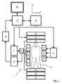
Fig. 1 shows a MR device according to the invention; -
Fig. 2 shows a diagram illustrating the scheme of saturation frequency offsets used for APT MR imaging according to the invention, -
Fig. 3 shows a diagram illustrating a first embodiment of the APT acquisition scheme according to the invention; -
Fig. 4 shows a diagram illustrating a second embodiment of the APT acquisition scheme according to the invention. - With reference to
Figure 1 , aMR device 1 is shown. The device comprises superconducting or resistive main magnet coils 2 such that a substantially uniform, temporally constant main magnetic field B0 is created along a z-axis through an examination volume. The device further comprises a set of (1st, 2nd, and - where applicable - 3rd order) shimming coils 2', wherein the current flow through the individual shimming coils of the set 2' is controllable for the purpose of minimizing B0 deviations within the examination volume. - A magnetic resonance generation and manipulation system applies a series of RF pulses and switched magnetic field gradients to invert or excite nuclear magnetic spins, induce magnetic resonance, refocus magnetic resonance, manipulate magnetic resonance, spatially and otherwise encode the magnetic resonance, saturate spins, and the like to perform MR imaging.
- More specifically, a
gradient pulse amplifier 3 applies current pulses to selected ones of whole-body gradient coils 4, 5 and 6 along x, y and z-axes of the examination volume. A digitalRF frequency transmitter 7 transmits RF pulses or pulse packets, via a send-/receiveswitch 8, to abody RF coil 9 to transmit RF pulses into the examination volume. A typical MR imaging sequence is composed of a packet of RF pulse segments which, together with any applied magnetic field gradients, achieve a selected manipulation of nuclear magnetic resonance. The RF pulses are used to saturate, excite resonance, invert magnetization, refocus resonance, or manipulate resonance and select a portion of abody 10 positioned in the examination volume. The MR signals are also picked up by thebody RF coil 9. - For generation of MR images of limited regions of the
body 10 by means of parallel imaging, a set of local array RF coils 11, 12, 13 are placed contiguous to the region selected for imaging. The array coils 11, 12, 13 can be used to receive MR signals induced by body-coil RF transmissions. - The resultant MR signals are picked up by the
body RF coil 9 and/or by the array RF coils 11, 12, 13 and demodulated by areceiver 14 preferably including a preamplifier (not shown). Thereceiver 14 is connected to the RF coils 9, 11, 12 and 13 via send-/receiveswitch 8. - A
host computer 15 controls the shimming coils 2' as well as thegradient pulse amplifier 3 and thetransmitter 7 to generate any of a plurality of MR imaging sequences, such as echo planar imaging (EPI), echo volume imaging, gradient and spin echo imaging, fast spin echo imaging, and the like. For the selected sequence, thereceiver 14 receives a single or a plurality of MR data lines in rapid succession following each RF excitation pulse. Adata acquisition system 16 performs analog-to-digital conversion of the received signals and converts each MR data line to a digital format suitable for further processing. In modern MR devices thedata acquisition system 16 is a separate computer which is specialized in the acquisition of raw image data. - Ultimately, the digital raw image data are reconstructed into an image representation by a
reconstruction processor 17 which applies a Fourier transform or other appropriate reconstruction algorithms, such as SENSE or GRAPPA. The MR image may represent a planar slice through the patient, an array of parallel planar slices, a three-dimensional volume, or the like. The image is then stored in an image memory where it may be accessed for converting slices, projections, or other portions of the image representation into appropriate format for visualization, for example via avideo monitor 18 which provides a man-readable display of the resultant MR image. - In accordance with the invention, the portion of the
body 10 is subjected to saturation RF pulses at different saturation frequency offsets prior to acquisition of MR signals by means of a spin echo sequence, which is preferably a fast spin echo (FSE) or turbo spin echo (TSE) sequence or a related pulse sequence like GRASE. The saturation RF pulses are irradiated via thebody RF coil 9 and/or via the array RF coils 11, 12, 13, wherein the saturation frequency offset relative to the MR frequency of water protons is set by appropriate control of thetransmitter 7 via thehost computer 15. As shown inFigure 2 , different saturation frequency offsets are applied around +/- 3.5 ppm around the MR frequency of water protons (0 ppm). The different saturation frequency offsets are indicated by black arrows inFigure 2 . A further reference acquisition may be performed "off-resonant", i.e. with a very large frequency offset which leaves the MR signal amplitude of water protons unaffected or with the RF saturation power switched off. This is indicated by the leftmost black arrow inFigure 2 . - According to the invention, MR signal acquisition steps are repeated several times, wherein the saturation frequency offset and the echo time shifts in the spin echo sequence are varied, such that a different combination of saturation frequency offset and echo time shift is applied in two or more of the repetitions. Finally, an APT MR image is reconstructed from the acquired MR signals. This means that the reconstruction of the MR image includes deriving the spatial distribution of amide protons within the portion of the
body 10 from an asymmetry analysis of the amplitude of the acquired MR signals as a function of the saturation frequency offset. This asymmetry analysis, which is conventionally applied in APT MR imaging, is very sensitive to any inhomogeneity of the main magnetic field B0. This is taken into account by the method of the invention by determination of the spatial variation of B0 from the acquired MR signals by means of a single-point or multi-point Dixon technique. The determined spatial variation of B0 is then used for a corresponding saturation frequency offset correction in the asymmetry analysis. - For a determination of the spatial variation of B0, two specific strategies may be applied in accordance with the invention. These strategies are illustrated in the diagrams of
Figures 3 and4 . - The saturation steps are indicated in
Figures 3 and4 by SAT-3, SAT-2, SAT-1, SAT0, SAT+1, SAT+2 and SAT+3. Therein, SAT-1, SAT-2 and SAT-3 correspond to negative saturation frequency offsets, while SAT+1, SAT+2 and SAT+3 correspond to positive saturation frequency offsets. SAT0 corresponds to a reference measurement, in which an off-resonant frequency offset is applied, as mentioned above. ACQ1, ACQ2, ACQ3 and ACQ4 indicate MR signal acquisition steps using different echo time shifts (echo times TE1, TE2, TE3, TE4), respectively. - In the embodiment shown in
Figure 3 , an acquisition with any saturation frequency offset SAT-3, SAT-2, SAT-1, SAT0, SAT+1, SAT+2 and SAT+3 is repeated three times, each with a different echo time shift, indicated by ACQ1, ACQ2, and ACQ3. This results in an overall number of 21 repetitions. B0 mapping is preferably performed separately for each saturation frequency offset. - In the further embodiments shown
Figure 4 , the acquisitions with different saturation frequency offsets SAT-3, SAT-2, SAT-1, SAT+1, SAT+2, SAT+3 are performed only once, but with different echo time shifts, indicated by ACQ1, ACQ2, ACQ3 and ACQ4 (echo times TE1, TE2, TE3, TE4). ACQ0 indicates an acquisition without echo time shift (echo time TE0). A Dixon technique is applied to derive the B0 map from these acquisitions combining the data from different saturation frequency offsets. InFig. 4a three different echo time shifts (indicated by ACQ1, ACQ2, ACQ3) are applied with the saturation frequency offsets SAT+1, SAT+2 and SAT+3. The B0 map is derived from these acquisitions. No echo time shift is applied in the acquisitions with SAT-3, SAT-2, SAT-1 and SAT0. The B0 map is applied for correction in these acquisitions. InFig. 4b the different echo time shifts are also applied with SAT-3, SAT-2, SAT-1. No echo time shift is applied for SAT0. InFig. 4c three different echo time shifts (that are well-suited for B0 mapping) are applied with saturation frequency offsets SAT+1, SAT+2, SAT+3, while a single echo time shift that is well-suited for water/fat separation (indicated by ACQ4) is applied with saturation frequency offsets SAT0, SAT-1, SAT-2 and SAT-3. InFig. 4d no echo time shift is applied for SAT-3, SAT-2, SAT-1 and SAT+1, SAT+2, SAT+3, while three different echo time shifts are applied with SAT-0 (for B0 mapping). - For positive saturation frequency offsets, the MR signal amplitude of water protons is expected to vary slightly between the individual acquisitions due to different extents of direct saturation of water protons and due to the relevant saturation transfer effects, as mentioned above. The resulting slight signal variation may be addressed in different ways for the purpose of B0 mapping. One option is to simply ignore this small signal variation. This option can be used in practice, but it may result in a somewhat reduced precision of the determined B0 map. Another option is to minimize the influence of the signal variations by choosing appropriate echo time shifts, where the Dixon-based B0 determination is most robust against signal variations. A further option is to apply an appropriate mathematical model of the acquired composite complex MR signals and to derive the B0 from the resulting model parameters. Different strategies for MR signal modeling in Dixon imaging exist which can be applied in accordance with the invention are per se known in the art.
- In an embodiment of the invention, the composite complex signal S acquired with SAT+1, SAT+2, SAT+3 may be modeled by:


or, by using a linear approximation, as:


wherein W denotes the water signal contribution, F denotes the fat signal contribution, P and ΔP denote phase errors, and c denotes coefficients that describe the amplitude and phase of a unit fat signal at the respective echo time shift. W, F, P, and ΔP are considered as unknowns, while S and c are considered as knowns. In the first case (without approximation), the number of knowns (real and imaginary components of S) and the number of unknowns (real W1-W3, real F, phase of P and ΔP) are both equal to six. In the second case (with approximation), the number of knowns exceeds the number of unknowns by one. The acquisition with saturation frequency offset SAT0 may be included as fourth equation, again with a different W and the same F. B0 can be derive on a voxel-by-voxel basis from the resulting model parameters. - The spatial variation of B0 can be assumed not to change between the individual MR signal acquisition steps. Accordingly, once the spatial variation of B0 has been determined in the afore-described manner, the obtained B0 map can be used for suppression of signal contributions from fat spins. A Dixon method can be applied to perform a water/fat separation after demodulation of B0-induced phase errors. The echo time values can be optimized to maximize the signal-to-noise ratio in the resulting water MR images, for instance by choosing echo time shifts at which signal contributions from water and fat spins are in quadrature, i.e. 90° out of phase. If other echo time values are preferred for B0 mapping than are favorable for Dixon water/fat separation, some acquisitions with appropriate saturation frequency offsets may be repeated with correspondingly chosen echo time values.
- For positive saturation frequency offsets, one of the schemes illustrated in
Figure 4 for obtaining the B0 map can also be employed to suppress signal contributions from fat spins. For the acquisitions with negative saturation frequency offsets near the chemical shift of fat protons, the extent of saturation of fat protons imposed by the saturation RF pulses can be modeled on the basis of an appropriate mathematical model, taking the RF pulse parameters (for example shape, bandwidth) and the spectrum of the fat protons (for example number of peaks, resonance frequencies, resonance areas, line widths) into account. - In an exemplary embodiment, the composite signal S acquired with SAT-1, SAT-2, SAT-3 may be modeled as:


or, using a linear approximation, as:


wherein d denotes coefficients that describe the relative extent of fat suppression. For the acquisitions with both, positive and negative saturation frequency offsets, F may be considered as unknown, or F may be considered as known from the water/fat separation in the acquisition with off-resonant saturation SAT0. - After water/fat separation, an APT/CEST MR image at the desired saturation offset frequency (e.g. +3.5 ppm for APT) can be reconstructed by means of the above-mentioned asymmetry analysis of the voxel-wise amplitude of the water MR images as a function of the saturation frequency offset. Therein, the asymmetry analysis involves a saturation frequency offset correction based on the determined spatial variation of B0., e.g. by means of a voxel-by-voxel Lagrange interpolation of the images taken at different saturation frequency offsets.
Claims (10)
- A method of MR imaging of at least a portion of a body (10) placed in a main magnetic field B0 within the examination volume of a MR device (1), the method comprising the following steps:a) subjecting the portion of the body (10) to a saturation RF pulse at a saturation frequency offset;b) subjecting the portion of the body (10) to an imaging sequence comprising at least one excitation RF pulse and switched magnetic field gradients, whereby MR signals are acquired from the portion of the body (10) as spin echo signals;c) repeating steps a) and b) two or more times, wherein the saturation frequency offset and/or a echo time shift in the imaging sequence are varied, such that a different combination of saturation frequency offset and echo time shift is applied in two or more of the repetitions;d) reconstructing a MR image from the acquired MR signals.
- Method of claim 1, wherein contributions from fat spins and water spins to the acquired MR signals are separated on the basis of a single-point or multi-point Dixon technique.
- Method of claim 1 or 2, wherein the spatial variation of B0 within the portion of the body (10) is determined from the acquired MR signals by means of a single-point or multi-point Dixon technique.
- Method of claim 3, wherein the reconstruction of the MR image includes deriving the spatial distribution of amide protons within the portion of the body (10) from an asymmetry analysis of the amplitude of the acquired MR signals as a function of the saturation frequency, which asymmetry analysis involves a saturation frequency offset correction based on the determined spatial variation of B0.
- Method of claim 3 or 4, wherein the reconstruction of the MR image includes deriving the spatial pH distribution within the portion of the body (10) from an asymmetry analysis of the amplitude of the acquired MR signals as a function of the saturation frequency, which asymmetry analysis involves a saturation frequency offset correction based on the determined spatial variation of B0.
- Method of any one of claims 1-5, wherein saturation RF pulses are applied in different repetitions of steps a) and b) at positive and negative saturation frequency offsets around the resonance frequency of water protons.
- Method of any one of claims 1-6, wherein steps a) and b) are repeated two or more times with the same saturation frequency offset and with a different echo time shift in two or more of the repetitions.
- Method of any one of claims 1-7, wherein steps a) and b) are repeated two or more times with a different saturation frequency offset and with a different echo time shift in two or more of the repetitions.
- MR device comprising:- at least one main magnet coil (2) for generating a uniform, steady magnetic field within an examination volume;- a number of gradient coils (4, 5, 6) for generating switched magnetic field gradients in different spatial directions within the examination volume;- at least one RF coil (9) for generating RF pulses within the examination volume and/or for receiving MR signals from a body (10) of a patient positioned in the examination volume;- a control unit (15) for controlling the temporal succession of RF pulses and switched magnetic field gradients; and- a reconstruction unit (17) for reconstructing a MR image from the received MR signals,wherein the MR device (1) is arranged to perform the following steps:a) subjecting the portion of the body (10) to a saturation RF pulse at a saturation frequency offset;b) subjecting the portion of the body (10) to an imaging sequence comprising at least one excitation RF pulse and switched magnetic field gradients, whereby MR signals are acquired from the portion of the body (10) as spin echo signals;c) repeating steps a) and b) two or more times, wherein the saturation frequency offset and/or a echo time shift in the imaging sequence are varied, such that a different combination of saturation frequency offset and echo time shift is applied in two or more of the repetitions;d) reconstructing a MR image from the acquired MR signals.
- Computer program to be run on a MR device, which computer program comprises instructions for:a) generating a saturation RF pulse at a saturation frequency offset;b) generating an imaging sequence comprising at least one excitation RF pulse and switched magnetic field gradients, whereby MR signals are acquired from the portion of the body (10) as spin echo signals;c) repeating steps a) and b) two or more times, wherein the saturation frequency offset and/or a echo time shift in the imaging sequence are varied, such that a different combination of saturation frequency offset and echo time shift is applied in two or more of the repetitions;d) reconstructing a MR image from the acquired MR signals.
Priority Applications (7)
| Application Number | Priority Date | Filing Date | Title |
|---|---|---|---|
| EP12162970.3A EP2648014A1 (en) | 2012-04-03 | 2012-04-03 | MR imaging using APT contrast enhancement and sampling at multiple echo times |
| RU2014144291/28A RU2605516C2 (en) | 2012-04-03 | 2013-03-21 | Magnetic resonance (mr) |
| PCT/IB2013/052244 WO2013150407A1 (en) | 2012-04-03 | 2013-03-21 | Mr imaging using apt contrast enhancement and sampling at multiple echo times |
| US14/387,421 US9766313B2 (en) | 2012-04-03 | 2013-03-21 | MR imaging using apt contrast enhancement and sampling at multiple echo times |
| JP2015503963A JP6255005B2 (en) | 2012-04-03 | 2013-03-21 | MR imaging using APT contrast enhancement and sampling at multiple echo times |
| EP13721089.4A EP2839308A1 (en) | 2012-04-03 | 2013-03-21 | Mr imaging using apt contrast enhancement and sampling at multiple echo times |
| CN201380018487.XA CN104204839B (en) | 2012-04-03 | 2013-03-21 | MR imaging using APT contrast enhancement and sampling at multiple echo times |
Applications Claiming Priority (1)
| Application Number | Priority Date | Filing Date | Title |
|---|---|---|---|
| EP12162970.3A EP2648014A1 (en) | 2012-04-03 | 2012-04-03 | MR imaging using APT contrast enhancement and sampling at multiple echo times |
Publications (1)
| Publication Number | Publication Date |
|---|---|
| EP2648014A1 true EP2648014A1 (en) | 2013-10-09 |
Family
ID=45939206
Family Applications (2)
| Application Number | Title | Priority Date | Filing Date |
|---|---|---|---|
| EP12162970.3A Withdrawn EP2648014A1 (en) | 2012-04-03 | 2012-04-03 | MR imaging using APT contrast enhancement and sampling at multiple echo times |
| EP13721089.4A Withdrawn EP2839308A1 (en) | 2012-04-03 | 2013-03-21 | Mr imaging using apt contrast enhancement and sampling at multiple echo times |
Family Applications After (1)
| Application Number | Title | Priority Date | Filing Date |
|---|---|---|---|
| EP13721089.4A Withdrawn EP2839308A1 (en) | 2012-04-03 | 2013-03-21 | Mr imaging using apt contrast enhancement and sampling at multiple echo times |
Country Status (6)
| Country | Link |
|---|---|
| US (1) | US9766313B2 (en) |
| EP (2) | EP2648014A1 (en) |
| JP (1) | JP6255005B2 (en) |
| CN (1) | CN104204839B (en) |
| RU (1) | RU2605516C2 (en) |
| WO (1) | WO2013150407A1 (en) |
Cited By (3)
| Publication number | Priority date | Publication date | Assignee | Title |
|---|---|---|---|---|
| EP3511728A1 (en) * | 2018-01-12 | 2019-07-17 | Koninklijke Philips N.V. | Single-point dixon method for fat-water separation in chemical exchange saturation transfer magnetic resonance imaging |
| CN111566497A (en) * | 2018-01-11 | 2020-08-21 | 皇家飞利浦有限公司 | Magnetization transfer based metrology for chemical exchange saturation transfer MRI |
| US20210333342A1 (en) * | 2020-01-07 | 2021-10-28 | Synaptive Medical Inc. | Dynamic b0 shimming for improved fat saturation in magnetic resonance imaging (mri) |
Families Citing this family (16)
| Publication number | Priority date | Publication date | Assignee | Title |
|---|---|---|---|---|
| EP2515138A1 (en) * | 2011-04-19 | 2012-10-24 | Koninklijke Philips Electronics N.V. | Motion triggered MR imaging using APT/CEST |
| EP3080634B1 (en) * | 2013-12-12 | 2021-04-21 | Koninklijke Philips N.V. | Zero echo time mr imaging with water/fat separation |
| EP2933651B1 (en) * | 2014-04-17 | 2020-03-18 | Albert-Ludwigs-Universität Freiburg | MRI Method of Hybrid Acquisition in 3D TSE |
| DE102015202062A1 (en) * | 2015-02-05 | 2016-08-11 | Siemens Healthcare Gmbh | Reconstruction of magnetic resonance image data for multiple chemical species in multi-echo imaging |
| CN104997511A (en) * | 2015-06-01 | 2015-10-28 | 中国科学院深圳先进技术研究院 | CESTR measuring method and system for magnetic resonance chemical exchange saturation transfer imaging |
| US10775462B2 (en) * | 2017-07-05 | 2020-09-15 | The General Hospital Corporation | System and method for direct saturation-corrected chemical exchange saturation transfer (DISC-CEST) |
| EP3511726A1 (en) * | 2018-01-12 | 2019-07-17 | Koninklijke Philips N.V. | Mri method for determining a magnetic field map from a b0 reference scan and a wassr scan |
| US10859656B2 (en) * | 2018-04-23 | 2020-12-08 | Cedars-Sinai Medical Center | Methods and systems for chemical exchange saturation transfer signal matching |
| EP3575814A1 (en) * | 2018-05-29 | 2019-12-04 | Koninklijke Philips N.V. | Motion detection in cest magnetic resonance imaging based on z-spectrum analysis |
| CN109521383B (en) | 2018-10-17 | 2019-08-30 | 浙江大学 | A kind of magnetic resonance CEST imaging sequence and device based on frequency stabilization module |
| CN109870663B (en) * | 2019-03-11 | 2021-02-26 | 深圳市信瑞达电力设备有限公司 | Driving method of magnetic circuit, magnetic measuring device and current detecting device |
| CN111722167B (en) * | 2019-03-19 | 2021-07-30 | 浙江大学 | Generation method, device and readable storage medium of chemical exchange saturation transfer-magnetic resonance imaging CEST-MRI sequence |
| US11439314B2 (en) | 2019-09-05 | 2022-09-13 | Canon Medical Systems Corporation | Image processing apparatus, magnetic resonance imaging apparatus, and image processing method |
| US11366189B2 (en) * | 2020-09-25 | 2022-06-21 | Uih America, Inc. | Systems and methods for magnetic resonance imaging |
| CN113171076B (en) * | 2021-04-29 | 2022-01-04 | 浙江大学 | CEST data fitting method, device and medium based on extrapolation magnetization transfer signal |
| CN113674248B (en) * | 2021-08-23 | 2022-08-12 | 广州市番禺区中心医院(广州市番禺区人民医院、广州市番禺区心血管疾病研究所) | Magnetic resonance amide proton transfer imaging magnetic susceptibility detection method and related equipment |
Citations (2)
| Publication number | Priority date | Publication date | Assignee | Title |
|---|---|---|---|---|
| US6962769B2 (en) | 2001-04-17 | 2005-11-08 | Brewer Science Inc. | Anti-reflective coating composition with improved spin bowl compatibility |
| US20120025823A1 (en) * | 2010-07-30 | 2012-02-02 | Vladimir Jellus | Method and device for magnetic resonance imaging |
Family Cites Families (5)
| Publication number | Priority date | Publication date | Assignee | Title |
|---|---|---|---|---|
| US8236572B2 (en) * | 2005-02-07 | 2012-08-07 | The Johns Hopkins University | Chemical exchange saturation transfer based MRI using reporter genes and MRI methods related thereto |
| RU2477146C2 (en) * | 2007-12-07 | 2013-03-10 | Кининклейке Филипс Электроникс Н.В. | Polymer carrier of drug preparations for visually-assissted delivery |
| US8278925B2 (en) * | 2008-03-26 | 2012-10-02 | The General Hospital Corporation | Method for relaxation-compensated fast multi-slice chemical exchange saturation transfer MRI |
| EP2199815A1 (en) * | 2008-12-22 | 2010-06-23 | Koninklijke Philips Electronics N.V. | MR imaging with CEST contrast enhancement |
| US8686727B2 (en) * | 2010-07-20 | 2014-04-01 | The Trustees Of The University Of Pennsylvania | CEST MRI methods for imaging of metabolites and the use of same as biomarkers |
-
2012
- 2012-04-03 EP EP12162970.3A patent/EP2648014A1/en not_active Withdrawn
-
2013
- 2013-03-21 RU RU2014144291/28A patent/RU2605516C2/en not_active IP Right Cessation
- 2013-03-21 WO PCT/IB2013/052244 patent/WO2013150407A1/en active Application Filing
- 2013-03-21 CN CN201380018487.XA patent/CN104204839B/en not_active Expired - Fee Related
- 2013-03-21 EP EP13721089.4A patent/EP2839308A1/en not_active Withdrawn
- 2013-03-21 JP JP2015503963A patent/JP6255005B2/en not_active Expired - Fee Related
- 2013-03-21 US US14/387,421 patent/US9766313B2/en active Active
Patent Citations (2)
| Publication number | Priority date | Publication date | Assignee | Title |
|---|---|---|---|---|
| US6962769B2 (en) | 2001-04-17 | 2005-11-08 | Brewer Science Inc. | Anti-reflective coating composition with improved spin bowl compatibility |
| US20120025823A1 (en) * | 2010-07-30 | 2012-02-02 | Vladimir Jellus | Method and device for magnetic resonance imaging |
Non-Patent Citations (6)
| Title |
|---|
| HE ZHU ET AL: "Fast 3D chemical exchange saturation transfer (CEST) imaging of the human brain", MAGNETIC RESONANCE IN MEDICINE, vol. 64, no. 3, 1 September 2010 (2010-09-01), pages 638 - 644, XP055027751, ISSN: 0740-3194, DOI: 10.1002/mrm.22546 * |
| J KEUPP ET AL: "CEST-Dixon MRI for Sensitive and Accurate Measurement of Amide Proton Transfer in Humans at 3T", PROCEEDINGS OF THE INTERNATIONAL SOCIETY FOR MAGNETIC RESONANCE IN MEDICINE, 18TH SCIENTIFIC MEETING AND EXHIBITION, STOCKHOLM, SWEDEN, 1-7 MAY 2010, 17 April 2010 (2010-04-17), pages 1520, XP055027571 * |
| PHILLIP ZHE SUN ET AL: "Suppression of lipid artifacts in amide proton transfer imaging", MAGNETIC RESONANCE IN MEDICINE, vol. 54, no. 1, 1 January 2005 (2005-01-01), pages 222 - 225, XP055027729, ISSN: 0740-3194, DOI: 10.1002/mrm.20530 * |
| W WEI ET AL: "Improving Amide Proton Transfer Imaging with Dual Echo B0 Mapping for Field Inhomogeneity Correction at 3T", PROCEEDINGS OF THE INTERNATIONAL SOCIETY FOR MAGNETIC RESONANCE IN MEDICINE, 18TH SCIENTIFIC MEETING AND EXHIBITION, STOCKHOLM, SWEDEN, 1-7 MAY 2010, 17 April 2010 (2010-04-17), pages 2986, XP055027758 * |
| ZHOU ET AL., MAGNETIC RESONANCE IN MEDICINE, vol. 60, 2008, pages 842 - 849 |
| ZHOU J ET AL: "Chemical exchange saturation transfer imaging and spectroscopy", PROGRESS IN NUCLEAR MAGNETIC RESONANCE SPECTROSCOPY, PERGAMON PRESS, OXFORD, GB, vol. 48, no. 2-3, 30 May 2006 (2006-05-30), pages 109 - 136, XP025078517, ISSN: 0079-6565, [retrieved on 20060530], DOI: 10.1016/J.PNMRS.2006.01.001 * |
Cited By (7)
| Publication number | Priority date | Publication date | Assignee | Title |
|---|---|---|---|---|
| CN111566497A (en) * | 2018-01-11 | 2020-08-21 | 皇家飞利浦有限公司 | Magnetization transfer based metrology for chemical exchange saturation transfer MRI |
| EP3511728A1 (en) * | 2018-01-12 | 2019-07-17 | Koninklijke Philips N.V. | Single-point dixon method for fat-water separation in chemical exchange saturation transfer magnetic resonance imaging |
| WO2019137858A1 (en) * | 2018-01-12 | 2019-07-18 | Koninklijke Philips N.V. | Single-point dixon method for fat-water separation in chemical exchange saturation transfer magnetic resonance imaging |
| CN111837047A (en) * | 2018-01-12 | 2020-10-27 | 皇家飞利浦有限公司 | Single point DIXON method for fat-water separation in chemical exchange saturation transfer magnetic resonance imaging |
| CN111837047B (en) * | 2018-01-12 | 2022-08-30 | 皇家飞利浦有限公司 | Single point DIXON method for fat-water separation in chemical exchange saturation transfer magnetic resonance imaging |
| US20210333342A1 (en) * | 2020-01-07 | 2021-10-28 | Synaptive Medical Inc. | Dynamic b0 shimming for improved fat saturation in magnetic resonance imaging (mri) |
| US11686795B2 (en) * | 2020-01-07 | 2023-06-27 | Synaptive Medical Inc. | Dynamic B0 shimming for improved fat saturation in magnetic resonance imaging (MRI) |
Also Published As
| Publication number | Publication date |
|---|---|
| CN104204839A (en) | 2014-12-10 |
| CN104204839B (en) | 2017-04-26 |
| RU2605516C2 (en) | 2016-12-20 |
| US9766313B2 (en) | 2017-09-19 |
| RU2014144291A (en) | 2016-05-27 |
| US20150051474A1 (en) | 2015-02-19 |
| WO2013150407A1 (en) | 2013-10-10 |
| JP6255005B2 (en) | 2017-12-27 |
| JP2015512317A (en) | 2015-04-27 |
| EP2839308A1 (en) | 2015-02-25 |
Similar Documents
| Publication | Publication Date | Title |
|---|---|---|
| US9766313B2 (en) | MR imaging using apt contrast enhancement and sampling at multiple echo times | |
| US9575154B2 (en) | MR imaging using a multi-point dixon technique | |
| EP2615470A1 (en) | MR imaging with B1 mapping | |
| US9983284B2 (en) | MRI with dixon-type water/fat separation and prior knowledge about inhomogeneity of the main magnetic field | |
| US20140070805A1 (en) | Mr imaging with b1 mapping | |
| CN105556326B (en) | MR imaging with DIXON-type water/fat separation | |
| US10359489B2 (en) | Phase sensitive inversion recovery MRI with water/fat separation | |
| EP3295194B1 (en) | Parallel mr imaging with rf coil sensitivity mapping | |
| EP3060116A1 (en) | Mr imaging with temperature mapping | |
| US10955506B2 (en) | Parallel MR imaging with spectral fat suppression | |
| US20140121492A1 (en) | Mri with separation of different chemical species using a spectral model | |
| US10859652B2 (en) | MR imaging with dixon-type water/fat separation | |
| EP2503348A1 (en) | MRI using a multi-point Dixon technique and a low resolution calibration scan | |
| EP3736593A1 (en) | Dual echo steady state mr imaging using bipolar diffusion gradients | |
| EP3702800A1 (en) | Epi mr imaging with distortion correction | |
| EP3531160A1 (en) | Eddy current correction in mr spectroscopy | |
| WO2016124397A1 (en) | Mr imaging with b1 mapping |
Legal Events
| Date | Code | Title | Description |
|---|---|---|---|
| PUAI | Public reference made under article 153(3) epc to a published international application that has entered the european phase |
Free format text: ORIGINAL CODE: 0009012 |
|
| AK | Designated contracting states |
Kind code of ref document: A1 Designated state(s): AL AT BE BG CH CY CZ DE DK EE ES FI FR GB GR HR HU IE IS IT LI LT LU LV MC MK MT NL NO PL PT RO RS SE SI SK SM TR |
|
| AX | Request for extension of the european patent |
Extension state: BA ME |
|
| STAA | Information on the status of an ep patent application or granted ep patent |
Free format text: STATUS: THE APPLICATION IS DEEMED TO BE WITHDRAWN |
|
| 18D | Application deemed to be withdrawn |
Effective date: 20140410 |