EP2647910A2 - Diffusion combustor fuel nozzle - Google Patents
Diffusion combustor fuel nozzle Download PDFInfo
- Publication number
- EP2647910A2 EP2647910A2 EP13161763.1A EP13161763A EP2647910A2 EP 2647910 A2 EP2647910 A2 EP 2647910A2 EP 13161763 A EP13161763 A EP 13161763A EP 2647910 A2 EP2647910 A2 EP 2647910A2
- Authority
- EP
- European Patent Office
- Prior art keywords
- fuel
- flow
- fuel nozzle
- air
- swirler
- Prior art date
- Legal status (The legal status is an assumption and is not a legal conclusion. Google has not performed a legal analysis and makes no representation as to the accuracy of the status listed.)
- Withdrawn
Links
Images



Classifications
-
- F—MECHANICAL ENGINEERING; LIGHTING; HEATING; WEAPONS; BLASTING
- F23—COMBUSTION APPARATUS; COMBUSTION PROCESSES
- F23R—GENERATING COMBUSTION PRODUCTS OF HIGH PRESSURE OR HIGH VELOCITY, e.g. GAS-TURBINE COMBUSTION CHAMBERS
- F23R3/00—Continuous combustion chambers using liquid or gaseous fuel
- F23R3/02—Continuous combustion chambers using liquid or gaseous fuel characterised by the air-flow or gas-flow configuration
- F23R3/04—Air inlet arrangements
- F23R3/10—Air inlet arrangements for primary air
- F23R3/12—Air inlet arrangements for primary air inducing a vortex
-
- F—MECHANICAL ENGINEERING; LIGHTING; HEATING; WEAPONS; BLASTING
- F23—COMBUSTION APPARATUS; COMBUSTION PROCESSES
- F23R—GENERATING COMBUSTION PRODUCTS OF HIGH PRESSURE OR HIGH VELOCITY, e.g. GAS-TURBINE COMBUSTION CHAMBERS
- F23R3/00—Continuous combustion chambers using liquid or gaseous fuel
- F23R3/28—Continuous combustion chambers using liquid or gaseous fuel characterised by the fuel supply
Definitions
- the present application and the resultant patent relate generally to gas turbine engines and more particularly relate to a diffusion combustor fuel nozzle using a flow of curtain air to reduce emissions such as nitrogen oxides and the like while maintaining efficient performance.
- Operational efficiency in a gas turbine engine generally increases as the temperature of the combustion stream increases. Higher combustion stream temperatures, however, may result in the production of high levels of nitrogen oxides (NO x ) and other types of undesirable emissions. Such emissions may be subject to both federal and state regulations in the United States and also may be subject to similar regulations abroad. A balancing act thus exist between operating the gas turbine engine within an efficient temperature range while also ensuring that the output of nitrogen oxides and other types of regulated emissions remain well below mandated levels. Many other types of operational parameters also may be varied in providing such an optimized balance.
- NO x nitrogen oxides
- Many other types of operational parameters also may be varied in providing such an optimized balance.
- a diffusion-type combustor i.e., non-premixed
- fuel is injected into the air swirler.
- the air also flows through the swirler so as to mix with the fuel for downstream combustion.
- the fuel and the resultant hot combustion gases may become entrained in a recirculation zone downstream of the swirler.
- the liner surrounding the fuel nozzles and the combustion chamber may experience relatively high-head end temperatures.
- the relatively high head-end temperatures may be increased even further when the combustor bums certain types of liquid fuels. Such high temperatures may have an impact on the integrity and the lifetime of the liner and other components.
- Such a fuel nozzle for a diffusion combustor may efficiently combust the fuel and the air streams therein with limited emissions while also limiting liner temperatures for increased component lifetime.
- the present invention provides a fuel nozzle for use with one or more flows of fuel and a flow of air in a combustor.
- the fuel nozzle may include one or more gas fuel passages for the one or more of flows of fuel, a swirler with one or more air chambers therein surrounding the gas fuel passages, and a collar with one or more curtain slots surrounding the swirler.
- the flow of air is divided between a swirler flow through the air chambers and a curtain flow through the curtain slots.
- the present invention further provides a method of operating a fuel nozzle in a combustor.
- the method may include the steps of providing one or more flows of fuel through the fuel nozzle, providing a flow of air about the fuel nozzle, and dividing the flow of air into a swirler flow through a swirler and a curtain flow through a collar such that the curtain flow surrounds a mixed fuel-air flow of the swirler flow and the one or more flows of fuel.
- the present invention further provides a fuel nozzle for use with one or more flows of fuel and a flow of air in a diffusion combustor.
- the fuel nozzle may include one or more gas fuel passages for the flows of fuel, a swirler surrounding the gas fuel passages, and a collar surrounding the swirler.
- the swirler may include a number of swirl vanes that define a number of air chambers therein.
- the collar may include a number of curtain slots. The flow of air may be divided between a swirler flow through the air chambers and a curtain flow through the curtain slots.
- Fig. 1 shows a schematic view of gas turbine engine 10 as may be used herein.
- the gas turbine engine 10 may include a compressor 15.
- the compressor 15 compresses an incoming flow of air 20.
- the compressor 15 delivers the compressed flow of air 20 to a combustor 25.
- the combustor 25 mixes the compressed flow of air 20 with a pressurized flow of fuel 30 and ignites the mixture to create a flow of combustion gases 35.
- the gas turbine engine 10 may include any number of combustors 25.
- the flow of combustion gases 35 is in turn delivered to a turbine 40.
- the flow of combustion gases 35 drives the turbine 40 so as to produce mechanical work.
- the mechanical work produced in the turbine 40 drives the compressor 15 via a shaft 45 and an external load 50 such as an electrical generator and the like.
- Other configurations and other components may be used herein.
- the gas turbine engine 10 may use natural gas, various types of syngas, and/or other types of fuels.
- the gas turbine engine 10 may be any one of a number of different gas turbine engines offered by General Electric Company of Schenectady, New York, including, but not limited to, those such as a 7 or a 9 series heavy duty gas turbine engine and the like.
- the gas turbine engine 10 may have different configurations and may use other types of components.
- Other types of gas turbine engines also may be used herein.
- Multiple gas turbine engines, other types of turbines, and other types of power generation equipment also may be used herein together.
- Fig. 2 shows an example of the combustor 25 that may be used with the gas turbine engine 10 and the like.
- the combustor 25 may include a number of fuel nozzles 55 therein. As described above, each of the fuel nozzles 55 may direct the flow of air 20, the flow of fuel 30, and optional flows of other fluids for combustion therein. Any number of the fuel nozzles 55 may be used in any configuration.
- the fuel nozzles 55 may be attached to an end cover 60 near a head-end 65 of the combustor 25. The flows of the air 20 and the fuel 30 may be directed through the end cover 60 and the head-end 65 into each of the fuel nozzles 55 so as to distribute a fuel-air mixture downstream thereof.
- the combustor 25 also may include a combustion chamber 70 therein.
- the combustion chamber 70 may be defined by a combustion casing 75, a combustion liner 80, a flow sleeve 85, and the like.
- the liner 80 and the flow sleeve 85 may be coaxially positioned with respect to one another so as to define an air pathway 90 for the flow of air 20 therethrough.
- the combustion chamber 70 may lead to a downstream transition piece 95.
- the flows of the air 20 and the fuel 30 may mix downstream of the fuel nozzles 55 for combustion within the combustion chamber 70.
- the flow of combustion gases 35 then may be directed via the transition piece 95 towards the turbine 40 so as to produce useful work therein.
- Other components and other configuration also may be used herein.
- Figs. 3 and 4 show an example of the fuel nozzle 55 that may be used with the combustor 25 and the like.
- the fuel nozzle 55 may be a diffusion fuel nozzle 100. More specifically, the fuel nozzle 55 may be a dual fuel nozzle 105.
- the flow of fuel 30 may include one or more flows of a gas fuel 110 such as natural gas and one or more flows of a liquid fuel 115 such as a syngas and the like. Other types of fuel flows and other types of combinations of fuel flows may be used herein.
- the fuel nozzle 55 may include an outer tube 120.
- the outer tube 120 may lead to a downstream face 125 with a fuel nozzle tip 130.
- the outer tube 120 may include a number of fuel, air, and water passages therein.
- a number of gas fuel passages 135 may extend therethrough and may be axially positioned about the downstream face 125.
- the gas fuel passages 135 may be in communication with the flow of gas fuel 110.
- a number of tip outlets 140 also may extend therethrough and may be positioned about the fuel nozzle tip 130.
- the tip outlets 140 may include a liquid fuel outlet 145 in communication with the flow of liquid fuel 115.
- the tip outlets 140 also may include an atomizing air outlet 150 in communication with a flow of atomizing air as well as a water outlet 155 in communication with a flow of water.
- Other components and other configurations may be used herein.
- a swirler 160 may be positioned about the downstream face 125 of the fuel nozzle 55.
- the swirler 160 may include a number of swirl vanes 165.
- the swirl vanes 165 may define a number of air chambers 170.
- the air chambers 170 may be in communication with the flow of air 20 from the end cover 60.
- a number of swirler passages 175 may extend from the gas fuel passages 135 to the air chambers 170 for at least a portion of the flow of gas fuel 110.
- the flow of air 20 and the flow of gas fuel 110 thus may begin to mix about the swirler 160 for combustion within the downstream combustion chamber 70.
- all of the flow of air 20 thus passes through the air chambers 170 of the swirler 160 as a swirler flow 180.
- a collar 185 may surround the swirler 160.
- a cone (not shown) may extend from the fuel nozzle 55 to the liner 80.
- Other types of fuel nozzles 55 and other types of combustors 25 may be used herein with differing types of fuel.
- other components and other configurations may be used herein.
- Fig. 5 and Fig. 6 show a fuel nozzle 200 as may be described herein.
- the fuel nozzle 200 may be a diffusion nozzle 210 with little to no upstream fuel-air premixing.
- the fuel nozzle 200 also may be a dual fuel nozzle 220 for use with both the flow of gas fuel 110 and the flow of the liquid fuel 115. Other types of flows may be used herein.
- the fuel nozzle 200 thus includes one or more gas fuel passages 230 extending therethrough.
- the gas fuel passages 230 may extend towards a downstream face 240.
- the fuel nozzle 200 also may include a number of tip outlets 250.
- the tip outlets 250 may be positioned about a fuel nozzle tip 260 about the downstream face 240.
- the tip outlets 250 may include one or more liquid fuel outlets 270 as well as outlets for atomizing air, water, and the like. Other components and other configurations also may be used herein.
- the fuel nozzle 200 also may include a swirler 280 positioned about the downstream face 240 thereof.
- the swirler 280 surrounds fuel nozzle tip 260.
- the swirler 280 may include a number of swirl vanes 290 that define a number of air chambers 300 extending therethrough.
- the swirl vanes 290 and the air chambers 300 may have any size, shape, or configuration. Any number of the swirl vanes 290 and the air chambers 300 may be used herein.
- a number of swirl vane gas fuel passages 310 may extend from one or more of the gas fuel passages 230 to the air chambers 300 for at least a portion of the flow of gas fuel 110 therethrough.
- An air inlet 320 may be defined on the upstream end of the swirler 280 in communication with the flow of air 20 from the end cover 60.
- the air inlet 320 may have any size, shape, or configuration. Other components and other configurations also may be used herein.
- the fuel nozzle 200 also may include a collar 330 surrounding the swirler 280.
- a cone 340 may extend from the collar 330 towards the liner 80.
- the collar 330 may include a number of curtain slots 350 extending therethrough.
- the curtain slots 350 may include an angled configuration 360.
- the curtain slots 350 may have any size, shape, or configuration. Any number of the curtain slots 350 may be used herein.
- the curtain slots 350 may extend from about the air inlet 320 to the downstream face 240.
- the flow of air 20 thus may be divided into a swirler flow 370 passing through the air chambers 300 of the swirler 280 and a curtain flow 380 extending through the curtain slots 350 of the collar 330.
- the respective proportions of the swirler flows 370 and the curtain flows 380 may vary. Other components and other configurations may be used herein.
- the flow of gas fuel 110 extends through the gas fuel passages 230, through the swirler vane gas fuel passages 310, and into the air chambers 300 of the swirler 280.
- the flow of liquid fuel 115, the atomizing airflow, and the water flow pass through the tip outlets 250.
- the flow of air 20 flows through the air inlet 320 and then may be split into the swirler flow 370 passing through the air chambers 300 and the curtain flow 380 passing through the curtain slots 350 of the collar 300.
- the flow of gas fuel 110 and the swirler flow 370 begin to mix within the air chambers 300 of the swirler 280 to create a mixed fuel-air flow 390 extending into the combustion chamber 70.
- the curtain flow 380 may be injected at an angle given the angled configuration 360 of the curtain slots 350. The curtain flow 380 thus serves to blanket this mixed fuel-air flow 390.
- Injecting the curtain flow 380 prevents the mixed fuel-air flow 390 and/or the flow of combustion gases 35 from being entrained in a recirculation zone about the fuel nozzle 200.
- the blanketing effect of the curtain flow 380 thus may provide a reduction in NO x emissions and the like.
- the flammable value of the fuel-air flow 390 may be reduced so as to improve emissions and also extend the useful lifetime of the liner 80 and other components in the hot gas path.
- the water to fuel ratio also may be reduced herein.
- the fuel nozzle 200 described herein thus provides low natural gas emissions with wide liquid fuel flexibility. As opposed to the current approach of increasing fuel-air premixing, the fuel nozzle 200 described herein actually lowers premixing so as to improve overall NO x emissions. This non-intuitive approach of lowering fuel-air premixing is distinct from such current fuel nozzle designs and operational theories. The use of the curtain flow 380 herein thus improves emissions and overall component lifetime.
Landscapes
- Engineering & Computer Science (AREA)
- Chemical & Material Sciences (AREA)
- Combustion & Propulsion (AREA)
- Mechanical Engineering (AREA)
- General Engineering & Computer Science (AREA)
- Spray-Type Burners (AREA)
Abstract
The present application thus provides a fuel nozzle (200) for use with one or more flows of fuel and a flow of air (20) in a combustor. The fuel nozzle (200) may include one or more gas fuel passages (310) for the one or more of flows of fuel (30), a swirler (280) with one or more air chambers (300) therein surrounding the gas fuel passages (310), and a collar (330) with one or more curtain slots (350) surrounding the swirler (280). The flow of air is (20) divided between a swirler flow (370) through the air chambers (300) and a curtain flow (380) through the curtain slots (350).
Description
- The present application and the resultant patent relate generally to gas turbine engines and more particularly relate to a diffusion combustor fuel nozzle using a flow of curtain air to reduce emissions such as nitrogen oxides and the like while maintaining efficient performance.
- Operational efficiency in a gas turbine engine generally increases as the temperature of the combustion stream increases. Higher combustion stream temperatures, however, may result in the production of high levels of nitrogen oxides (NOx) and other types of undesirable emissions. Such emissions may be subject to both federal and state regulations in the United States and also may be subject to similar regulations abroad. A balancing act thus exist between operating the gas turbine engine within an efficient temperature range while also ensuring that the output of nitrogen oxides and other types of regulated emissions remain well below mandated levels. Many other types of operational parameters also may be varied in providing such an optimized balance.
- In a gas turbine engine that includes a diffusion-type combustor, i.e., non-premixed, fuel is injected into the air swirler. The air also flows through the swirler so as to mix with the fuel for downstream combustion. The fuel and the resultant hot combustion gases, however, may become entrained in a recirculation zone downstream of the swirler. As a result, the liner surrounding the fuel nozzles and the combustion chamber may experience relatively high-head end temperatures. Moreover, the relatively high head-end temperatures may be increased even further when the combustor bums certain types of liquid fuels. Such high temperatures may have an impact on the integrity and the lifetime of the liner and other components.
- There is thus a desire for an improved fuel nozzle for use in a combustor, particularly a diffusion type combustor in a gas turbine engine. Such a fuel nozzle for a diffusion combustor may efficiently combust the fuel and the air streams therein with limited emissions while also limiting liner temperatures for increased component lifetime.
- The present invention provides a fuel nozzle for use with one or more flows of fuel and a flow of air in a combustor. The fuel nozzle may include one or more gas fuel passages for the one or more of flows of fuel, a swirler with one or more air chambers therein surrounding the gas fuel passages, and a collar with one or more curtain slots surrounding the swirler. The flow of air is divided between a swirler flow through the air chambers and a curtain flow through the curtain slots.
- The present invention further provides a method of operating a fuel nozzle in a combustor. The method may include the steps of providing one or more flows of fuel through the fuel nozzle, providing a flow of air about the fuel nozzle, and dividing the flow of air into a swirler flow through a swirler and a curtain flow through a collar such that the curtain flow surrounds a mixed fuel-air flow of the swirler flow and the one or more flows of fuel.
- The present invention further provides a fuel nozzle for use with one or more flows of fuel and a flow of air in a diffusion combustor. The fuel nozzle may include one or more gas fuel passages for the flows of fuel, a swirler surrounding the gas fuel passages, and a collar surrounding the swirler. The swirler may include a number of swirl vanes that define a number of air chambers therein. The collar may include a number of curtain slots. The flow of air may be divided between a swirler flow through the air chambers and a curtain flow through the curtain slots.
- These and other features and improvements of the present application and the resultant patent will become apparent to one of ordinary skill in the art upon review of the following detailed description when taken in conjunction with the several drawings and the appended claims.
-
Fig. 1 is a schematic diagram of a gas turbine engine showing a compressor, a combustor, and a turbine. -
Fig. 2 is a side view of an example of the combustor such as that shown inFig. 1 . -
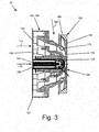
Fig. 3 is a side cross-sectional view of a fuel nozzle that may be used in the combustor ofFig. 2 . -
Fig. 4 is a front plan view of the fuel nozzle ofFig. 3 . -
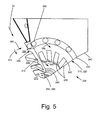
Fig. 5 is a partial perspective view of a fuel nozzle as may be described herein. -
Fig. 6 is a perspective view of a nozzle collar for use with the fuel nozzle ofFig. 5 . - Referring now to the drawings, in which like numerals refer to like elements throughout the several views,
Fig. 1 shows a schematic view ofgas turbine engine 10 as may be used herein. Thegas turbine engine 10 may include acompressor 15. Thecompressor 15 compresses an incoming flow ofair 20. Thecompressor 15 delivers the compressed flow ofair 20 to acombustor 25. Thecombustor 25 mixes the compressed flow ofair 20 with a pressurized flow offuel 30 and ignites the mixture to create a flow ofcombustion gases 35. Although only asingle combustor 25 is shown, thegas turbine engine 10 may include any number ofcombustors 25. The flow ofcombustion gases 35 is in turn delivered to aturbine 40. The flow ofcombustion gases 35 drives theturbine 40 so as to produce mechanical work. The mechanical work produced in theturbine 40 drives thecompressor 15 via ashaft 45 and anexternal load 50 such as an electrical generator and the like. Other configurations and other components may be used herein. - The
gas turbine engine 10 may use natural gas, various types of syngas, and/or other types of fuels. Thegas turbine engine 10 may be any one of a number of different gas turbine engines offered by General Electric Company of Schenectady, New York, including, but not limited to, those such as a 7 or a 9 series heavy duty gas turbine engine and the like. Thegas turbine engine 10 may have different configurations and may use other types of components. Other types of gas turbine engines also may be used herein. Multiple gas turbine engines, other types of turbines, and other types of power generation equipment also may be used herein together. -
Fig. 2 shows an example of thecombustor 25 that may be used with thegas turbine engine 10 and the like. Thecombustor 25 may include a number offuel nozzles 55 therein. As described above, each of thefuel nozzles 55 may direct the flow ofair 20, the flow offuel 30, and optional flows of other fluids for combustion therein. Any number of thefuel nozzles 55 may be used in any configuration. Thefuel nozzles 55 may be attached to anend cover 60 near a head-end 65 of thecombustor 25. The flows of theair 20 and thefuel 30 may be directed through theend cover 60 and the head-end 65 into each of thefuel nozzles 55 so as to distribute a fuel-air mixture downstream thereof. - The
combustor 25 also may include acombustion chamber 70 therein. Thecombustion chamber 70 may be defined by acombustion casing 75, acombustion liner 80, aflow sleeve 85, and the like. Theliner 80 and theflow sleeve 85 may be coaxially positioned with respect to one another so as to define anair pathway 90 for the flow ofair 20 therethrough. Thecombustion chamber 70 may lead to adownstream transition piece 95. The flows of theair 20 and thefuel 30 may mix downstream of thefuel nozzles 55 for combustion within thecombustion chamber 70. The flow ofcombustion gases 35 then may be directed via thetransition piece 95 towards theturbine 40 so as to produce useful work therein. Other components and other configuration also may be used herein. -
Figs. 3 and4 show an example of thefuel nozzle 55 that may be used with thecombustor 25 and the like. Thefuel nozzle 55 may be a diffusion fuel nozzle 100. More specifically, thefuel nozzle 55 may be a dual fuel nozzle 105. Given such, the flow offuel 30 may include one or more flows of agas fuel 110 such as natural gas and one or more flows of aliquid fuel 115 such as a syngas and the like. Other types of fuel flows and other types of combinations of fuel flows may be used herein. - The
fuel nozzle 55 may include anouter tube 120. Theouter tube 120 may lead to adownstream face 125 with afuel nozzle tip 130. Theouter tube 120 may include a number of fuel, air, and water passages therein. Specifically, a number ofgas fuel passages 135 may extend therethrough and may be axially positioned about thedownstream face 125. Thegas fuel passages 135 may be in communication with the flow ofgas fuel 110. A number oftip outlets 140 also may extend therethrough and may be positioned about thefuel nozzle tip 130. Thetip outlets 140 may include aliquid fuel outlet 145 in communication with the flow ofliquid fuel 115. Thetip outlets 140 also may include an atomizingair outlet 150 in communication with a flow of atomizing air as well as awater outlet 155 in communication with a flow of water. Other components and other configurations may be used herein. - A
swirler 160 may be positioned about thedownstream face 125 of thefuel nozzle 55. Theswirler 160 may include a number ofswirl vanes 165. The swirl vanes 165 may define a number ofair chambers 170. Theair chambers 170 may be in communication with the flow ofair 20 from theend cover 60. A number ofswirler passages 175 may extend from thegas fuel passages 135 to theair chambers 170 for at least a portion of the flow ofgas fuel 110. The flow ofair 20 and the flow ofgas fuel 110 thus may begin to mix about theswirler 160 for combustion within thedownstream combustion chamber 70. Generally described, all of the flow ofair 20 thus passes through theair chambers 170 of theswirler 160 as aswirler flow 180. Acollar 185 may surround theswirler 160. A cone (not shown) may extend from thefuel nozzle 55 to theliner 80. Other types offuel nozzles 55 and other types ofcombustors 25 may be used herein with differing types of fuel. Likewise, other components and other configurations may be used herein. -
Fig. 5 andFig. 6 show afuel nozzle 200 as may be described herein. Thefuel nozzle 200 may be a diffusion nozzle 210 with little to no upstream fuel-air premixing. Thefuel nozzle 200 also may be a dual fuel nozzle 220 for use with both the flow ofgas fuel 110 and the flow of theliquid fuel 115. Other types of flows may be used herein. In a manner similar to that described above, thefuel nozzle 200 thus includes one or moregas fuel passages 230 extending therethrough. Thegas fuel passages 230 may extend towards adownstream face 240. Thefuel nozzle 200 also may include a number of tip outlets 250. The tip outlets 250 may be positioned about a fuel nozzle tip 260 about thedownstream face 240. The tip outlets 250 may include one or moreliquid fuel outlets 270 as well as outlets for atomizing air, water, and the like. Other components and other configurations also may be used herein. - The
fuel nozzle 200 also may include aswirler 280 positioned about thedownstream face 240 thereof. Theswirler 280 surrounds fuel nozzle tip 260. Theswirler 280 may include a number ofswirl vanes 290 that define a number ofair chambers 300 extending therethrough. The swirl vanes 290 and theair chambers 300 may have any size, shape, or configuration. Any number of theswirl vanes 290 and theair chambers 300 may be used herein. A number of swirl vanegas fuel passages 310 may extend from one or more of thegas fuel passages 230 to theair chambers 300 for at least a portion of the flow ofgas fuel 110 therethrough. Anair inlet 320 may be defined on the upstream end of theswirler 280 in communication with the flow ofair 20 from theend cover 60. Theair inlet 320 may have any size, shape, or configuration. Other components and other configurations also may be used herein. - The
fuel nozzle 200 also may include acollar 330 surrounding theswirler 280. Acone 340 may extend from thecollar 330 towards theliner 80. Thecollar 330 may include a number ofcurtain slots 350 extending therethrough. Thecurtain slots 350 may include anangled configuration 360. Thecurtain slots 350 may have any size, shape, or configuration. Any number of thecurtain slots 350 may be used herein. Thecurtain slots 350 may extend from about theair inlet 320 to thedownstream face 240. The flow ofair 20 thus may be divided into aswirler flow 370 passing through theair chambers 300 of theswirler 280 and acurtain flow 380 extending through thecurtain slots 350 of thecollar 330. The respective proportions of the swirler flows 370 and the curtain flows 380 may vary. Other components and other configurations may be used herein. - In use, at least a portion of the flow of
gas fuel 110 extends through thegas fuel passages 230, through the swirler vanegas fuel passages 310, and into theair chambers 300 of theswirler 280. Likewise, the flow ofliquid fuel 115, the atomizing airflow, and the water flow pass through the tip outlets 250. The flow ofair 20 flows through theair inlet 320 and then may be split into theswirler flow 370 passing through theair chambers 300 and thecurtain flow 380 passing through thecurtain slots 350 of thecollar 300. The flow ofgas fuel 110 and theswirler flow 370 begin to mix within theair chambers 300 of theswirler 280 to create a mixed fuel-air flow 390 extending into thecombustion chamber 70. Thecurtain flow 380 may be injected at an angle given theangled configuration 360 of thecurtain slots 350. Thecurtain flow 380 thus serves to blanket this mixed fuel-air flow 390. - Injecting the
curtain flow 380 prevents the mixed fuel-air flow 390 and/or the flow ofcombustion gases 35 from being entrained in a recirculation zone about thefuel nozzle 200. The blanketing effect of thecurtain flow 380 thus may provide a reduction in NOx emissions and the like. Specifically, the flammable value of the fuel-air flow 390 may be reduced so as to improve emissions and also extend the useful lifetime of theliner 80 and other components in the hot gas path. The water to fuel ratio also may be reduced herein. - The
fuel nozzle 200 described herein thus provides low natural gas emissions with wide liquid fuel flexibility. As opposed to the current approach of increasing fuel-air premixing, thefuel nozzle 200 described herein actually lowers premixing so as to improve overall NOx emissions. This non-intuitive approach of lowering fuel-air premixing is distinct from such current fuel nozzle designs and operational theories. The use of thecurtain flow 380 herein thus improves emissions and overall component lifetime. - It should be apparent that the foregoing relates only to certain embodiments of the present application and the resultant patent. Numerous changes and modifications may be made herein by one of ordinary skill in the art without departing from the general spirit and scope of the invention as defined by the following claims and the equivalents thereof.
- Various aspects and embodiments of the present invention are defined by the following numbered clauses:
- 1. A fuel nozzle for use with one or more flows of fuel and a flow of air in a diffusion combustor, comprising:
- one or more gas fuel passages for the one or more of flows of fuel;
- a swirler surrounding the one or more gas fuel passages;
- the swirler comprising a plurality of swirl vanes defining a plurality of air chambers therein; and
- a collar surrounding the swirler;
- the collar comprising a plurality of curtain slots;
- wherein the flow of air is divided between a swirler flow through the plurality of air chambers and a curtain flow through the plurality of curtain slots.
- 2. The fuel nozzle of clause 1, wherein the plurality of swirl vanes comprises a plurality of gas fuel passages therethrough.
- 3. The fuel nozzle of any preceding clause, further comprising an air inlet in communication with the plurality of air chambers and the plurality of curtain slots.
- 4. The fuel nozzle of any preceding clause, wherein the collar comprises a cone extending therefrom.
- 5. The diffusion combustor of any preceding clause, wherein the one or more curtain slots comprise an angled configuration.
Claims (15)
- A fuel nozzle (100,200) for use with one or more flows of fuel (30) and a flow of air (20) in a combustor (25), comprising:one or more gas fuel passages (135,230) for the one or more of flows of fuel (30);a swirler (160) surrounding the one or more gas fuel passages (135,230), the swirler (160) comprising one or more air chambers (170) therein; anda collar (185) surrounding the swirler (160), the collar (185) comprising one or more curtain slots (350);wherein the flow of air (20) is divided between a swirler flow (180) through the one or more air chambers (170) and a curtain flow (380) through the one or more curtain slots (350).
- The fuel nozzle of claim 1, wherein the fuel nozzle (100,200) comprises a dual fuel nozzle (105,220) in a diffusion combustor (25).
- The fuel nozzle of claim 1 or 2, wherein the one or more flows of fuel (30) comprise a gas fuel (110) flowing through the one or more gas fuel passages (135,230).
- The fuel nozzle of claim 3, wherein the one or more gas fuel passages (230) extend towards a downstream face (240).
- The fuel nozzle of any of claims 1 to 4, wherein the one or more flows of fuel comprise a liquid fuel (115) flowing through a liquid fuel outlet (270).
- The fuel nozzle of claim 5, wherein the liquid fuel outlet (270) comprises a tip outlet (250) positioned about a fuel nozzle tip (260).
- The fuel nozzle of any preceding claim, wherein the swirler (160,280) comprises a plurality of swirl vanes (165,290) defining the one or more air chambers (170,300).
- The fuel nozzle of claim 7, wherein the plurality of swirl vanes (165,290) comprises a plurality of gas fuel passages (310) therethrough.
- The fuel nozzle of any preceding claim, further comprising an air inlet (320) in communication with the one or more air chambers (300) and the one or more curtain slots (350).
- The fuel nozzle of any preceding claim, wherein the collar (330) comprises a cone (340) extending therefrom.
- The fuel nozzle of any preceding claim, wherein the one or more curtain slots (350) comprise an angled configuration (360).
- The fuel nozzle of any preceding claim, wherein the curtain flow (380) surrounds the swirler flow (370).
- The fuel nozzle of any preceding claim, wherein the curtain flow (380) surrounds a fuel-air flow (390) of the swirler flow (370) and the one or more flows of fuel.
- The fuel nozzle of any preceding claim, wherein the curtain flow (380) extends along a liner (80).
- A method of operating a fuel nozzle (100,200) in a combustor (25), comprising:providing one or more flows of fuel (30) through the fuel nozzle (100,200);providing a flow of air (20) about the fuel nozzle (100,200); anddividing the flow of air into a swirler flow (370) through a swirler and a curtain flow (380) through a collar (330) such that the curtain flow (380) surrounds a fuel-air flow (390) of the swirler flow (370) and the one or more flows of fuel (30).
Applications Claiming Priority (1)
| Application Number | Priority Date | Filing Date | Title |
|---|---|---|---|
| US13/438,851 US20130263605A1 (en) | 2012-04-04 | 2012-04-04 | Diffusion Combustor Fuel Nozzle |
Publications (1)
| Publication Number | Publication Date |
|---|---|
| EP2647910A2 true EP2647910A2 (en) | 2013-10-09 |
Family
ID=48050472
Family Applications (1)
| Application Number | Title | Priority Date | Filing Date |
|---|---|---|---|
| EP13161763.1A Withdrawn EP2647910A2 (en) | 2012-04-04 | 2013-03-28 | Diffusion combustor fuel nozzle |
Country Status (5)
| Country | Link |
|---|---|
| US (1) | US20130263605A1 (en) |
| EP (1) | EP2647910A2 (en) |
| JP (1) | JP2013217635A (en) |
| CN (1) | CN103363524A (en) |
| RU (1) | RU2013114768A (en) |
Cited By (2)
| Publication number | Priority date | Publication date | Assignee | Title |
|---|---|---|---|---|
| RU2578785C1 (en) * | 2014-07-14 | 2016-03-27 | Публичное акционерное общество "МОТОР СИЧ" | Double fuel atomiser "gas plus fuel oil" |
| CN116293816A (en) * | 2023-04-18 | 2023-06-23 | 西安热工研究院有限公司 | Dual-fuel lean premixed multi-stage swirl nozzle |
Families Citing this family (6)
| Publication number | Priority date | Publication date | Assignee | Title |
|---|---|---|---|---|
| US10228137B2 (en) * | 2013-08-30 | 2019-03-12 | United Technologies Corporation | Dual fuel nozzle with swirling axial gas injection for a gas turbine engine |
| US10731861B2 (en) * | 2013-11-18 | 2020-08-04 | Raytheon Technologies Corporation | Dual fuel nozzle with concentric fuel passages for a gas turbine engine |
| CN114046539B (en) * | 2021-09-26 | 2023-04-07 | 中国航发湖南动力机械研究所 | Head structure of casing of back-flow combustion chamber |
| US12359813B2 (en) | 2021-12-29 | 2025-07-15 | General Electric Company | Engine fuel nozzle and swirler |
| US11774100B2 (en) * | 2022-01-14 | 2023-10-03 | General Electric Company | Combustor fuel nozzle assembly |
| CN119959450B (en) * | 2025-01-13 | 2025-12-16 | 华南理工大学 | Combustion experiment device for zero-carbon and carbon neutral fuel and working method thereof |
Family Cites Families (19)
| Publication number | Priority date | Publication date | Assignee | Title |
|---|---|---|---|---|
| JP3142924B2 (en) * | 1991-11-21 | 2001-03-07 | 株式会社日立製作所 | Gas turbine combustor nozzle |
| JP2839777B2 (en) * | 1991-12-24 | 1998-12-16 | 株式会社東芝 | Fuel injection nozzle for gas turbine combustor |
| JP2994856B2 (en) * | 1992-05-29 | 1999-12-27 | 三菱重工業株式会社 | Burner for gas turbine combustor |
| EP0700498B1 (en) * | 1993-06-01 | 1998-10-21 | Pratt & Whitney Canada, Inc. | Radially mounted air blast fuel injector |
| US5675971A (en) * | 1996-01-02 | 1997-10-14 | General Electric Company | Dual fuel mixer for gas turbine combustor |
| JP3498142B2 (en) * | 2001-08-01 | 2004-02-16 | 独立行政法人航空宇宙技術研究所 | Wall collision type liquid atomization nozzle |
| JP3956882B2 (en) * | 2002-08-22 | 2007-08-08 | 株式会社日立製作所 | Gas turbine combustor and gas turbine combustor remodeling method |
| US7143583B2 (en) * | 2002-08-22 | 2006-12-05 | Hitachi, Ltd. | Gas turbine combustor, combustion method of the gas turbine combustor, and method of remodeling a gas turbine combustor |
| JP4096056B2 (en) * | 2003-06-02 | 2008-06-04 | 独立行政法人 宇宙航空研究開発機構 | Fuel nozzle for gas turbine |
| JP2005016733A (en) * | 2003-06-23 | 2005-01-20 | Kawasaki Heavy Ind Ltd | Gas turbine combustor |
| US7000403B2 (en) * | 2004-03-12 | 2006-02-21 | Power Systems Mfg., Llc | Primary fuel nozzle having dual fuel capability |
| JP2007162998A (en) * | 2005-12-13 | 2007-06-28 | Kawasaki Heavy Ind Ltd | Fuel spray system for gas turbine engine |
| US7810333B2 (en) * | 2006-10-02 | 2010-10-12 | General Electric Company | Method and apparatus for operating a turbine engine |
| JP4364911B2 (en) * | 2007-02-15 | 2009-11-18 | 川崎重工業株式会社 | Gas turbine engine combustor |
| JP4421620B2 (en) * | 2007-02-15 | 2010-02-24 | 川崎重工業株式会社 | Gas turbine engine combustor |
| US7861528B2 (en) * | 2007-08-21 | 2011-01-04 | General Electric Company | Fuel nozzle and diffusion tip therefor |
| US8291688B2 (en) * | 2008-03-31 | 2012-10-23 | General Electric Company | Fuel nozzle to withstand a flameholding incident |
| US8281595B2 (en) * | 2008-05-28 | 2012-10-09 | General Electric Company | Fuse for flame holding abatement in premixer of combustion chamber of gas turbine and associated method |
| US8677760B2 (en) * | 2010-01-06 | 2014-03-25 | General Electric Company | Fuel nozzle with integrated passages and method of operation |
-
2012
- 2012-04-04 US US13/438,851 patent/US20130263605A1/en not_active Abandoned
-
2013
- 2013-03-28 EP EP13161763.1A patent/EP2647910A2/en not_active Withdrawn
- 2013-03-28 JP JP2013067726A patent/JP2013217635A/en active Pending
- 2013-04-03 RU RU2013114768/06A patent/RU2013114768A/en not_active Application Discontinuation
- 2013-04-08 CN CN2013101195727A patent/CN103363524A/en active Pending
Non-Patent Citations (1)
| Title |
|---|
| None |
Cited By (2)
| Publication number | Priority date | Publication date | Assignee | Title |
|---|---|---|---|---|
| RU2578785C1 (en) * | 2014-07-14 | 2016-03-27 | Публичное акционерное общество "МОТОР СИЧ" | Double fuel atomiser "gas plus fuel oil" |
| CN116293816A (en) * | 2023-04-18 | 2023-06-23 | 西安热工研究院有限公司 | Dual-fuel lean premixed multi-stage swirl nozzle |
Also Published As
| Publication number | Publication date |
|---|---|
| RU2013114768A (en) | 2014-10-10 |
| CN103363524A (en) | 2013-10-23 |
| US20130263605A1 (en) | 2013-10-10 |
| JP2013217635A (en) | 2013-10-24 |
Similar Documents
| Publication | Publication Date | Title |
|---|---|---|
| EP2647910A2 (en) | Diffusion combustor fuel nozzle | |
| CN102444911B (en) | There is the burner of poor pre-spraying nozzle fuel injection system | |
| US9115896B2 (en) | Fuel-air mixer for use with a combustor assembly | |
| US9416974B2 (en) | Combustor with fuel staggering for flame holding mitigation | |
| US8371101B2 (en) | Radial inlet guide vanes for a combustor | |
| US20110000215A1 (en) | Combustor Can Flow Conditioner | |
| EP2664854B1 (en) | Secondary combustion system | |
| EP2505921B1 (en) | Combustor crossfire tube having purge holes | |
| JP6220223B2 (en) | Micro mixer nozzle | |
| US20140260302A1 (en) | DIFFUSION COMBUSTOR FUEL NOZZLE FOR LIMITING NOx EMISSIONS | |
| US9068750B2 (en) | Combustor with a pre-nozzle mixing cap assembly | |
| EP2503243A1 (en) | Combustor with fuel nozzle liner having chevron ribs | |
| EP2618052A1 (en) | Fuel Nozzle | |
| CN102235668B (en) | For equipment and the method for burner | |
| US20160252018A1 (en) | Enhanced mixing tube elements |
Legal Events
| Date | Code | Title | Description |
|---|---|---|---|
| PUAI | Public reference made under article 153(3) epc to a published international application that has entered the european phase |
Free format text: ORIGINAL CODE: 0009012 |
|
| AK | Designated contracting states |
Kind code of ref document: A2 Designated state(s): AL AT BE BG CH CY CZ DE DK EE ES FI FR GB GR HR HU IE IS IT LI LT LU LV MC MK MT NL NO PL PT RO RS SE SI SK SM TR |
|
| AX | Request for extension of the european patent |
Extension state: BA ME |
|
| STAA | Information on the status of an ep patent application or granted ep patent |
Free format text: STATUS: THE APPLICATION IS DEEMED TO BE WITHDRAWN |
|
| 18D | Application deemed to be withdrawn |
Effective date: 20171003 |