EP2647829A1 - Recoil starter - Google Patents
Recoil starter Download PDFInfo
- Publication number
- EP2647829A1 EP2647829A1 EP11844680.6A EP11844680A EP2647829A1 EP 2647829 A1 EP2647829 A1 EP 2647829A1 EP 11844680 A EP11844680 A EP 11844680A EP 2647829 A1 EP2647829 A1 EP 2647829A1
- Authority
- EP
- European Patent Office
- Prior art keywords
- ratchet member
- drive pulley
- ratchet
- distal end
- rope reel
- Prior art date
- Legal status (The legal status is an assumption and is not a legal conclusion. Google has not performed a legal analysis and makes no representation as to the accuracy of the status listed.)
- Granted
Links
Images


Classifications
-
- F—MECHANICAL ENGINEERING; LIGHTING; HEATING; WEAPONS; BLASTING
- F02—COMBUSTION ENGINES; HOT-GAS OR COMBUSTION-PRODUCT ENGINE PLANTS
- F02N—STARTING OF COMBUSTION ENGINES; STARTING AIDS FOR SUCH ENGINES, NOT OTHERWISE PROVIDED FOR
- F02N3/00—Other muscle-operated starting apparatus
-
- F—MECHANICAL ENGINEERING; LIGHTING; HEATING; WEAPONS; BLASTING
- F02—COMBUSTION ENGINES; HOT-GAS OR COMBUSTION-PRODUCT ENGINE PLANTS
- F02N—STARTING OF COMBUSTION ENGINES; STARTING AIDS FOR SUCH ENGINES, NOT OTHERWISE PROVIDED FOR
- F02N15/00—Other power-operated starting apparatus; Component parts, details, or accessories, not provided for in, or of interest apart from groups F02N5/00 - F02N13/00
- F02N15/02—Gearing between starting-engines and started engines; Engagement or disengagement thereof
- F02N15/022—Gearing between starting-engines and started engines; Engagement or disengagement thereof the starter comprising an intermediate clutch
- F02N15/027—Gearing between starting-engines and started engines; Engagement or disengagement thereof the starter comprising an intermediate clutch of the pawl type
-
- F—MECHANICAL ENGINEERING; LIGHTING; HEATING; WEAPONS; BLASTING
- F02—COMBUSTION ENGINES; HOT-GAS OR COMBUSTION-PRODUCT ENGINE PLANTS
- F02N—STARTING OF COMBUSTION ENGINES; STARTING AIDS FOR SUCH ENGINES, NOT OTHERWISE PROVIDED FOR
- F02N3/00—Other muscle-operated starting apparatus
- F02N3/02—Other muscle-operated starting apparatus having pull-cords
Definitions
- the present invention relates to a recoil starter in which a recoil rope is pulled to rotate a rope reel so that the rotation of the rope reel is transmitted to a rotary member such as a drive pulley connected to a crankshaft of an engine through a ratchet mechanism so as to start the engine.
- a ratchet mechanism for transmitting the torque of the rope reel to the drive pulley.
- the ratchet mechanism is formed as follows. When the recoil rope is pulled to rotate the rope reel in an engine start direction, the ratchet mechanism engages with the drive pulley so as to transmit the torque to the drive pulley. However, once the engine starts, the ratchet mechanism is prevented from engaging with the drive pulley, so that the torque of the engine cannot be transmitted to the rope reel.
- Patent Literature 1 by the same applicant has given disclosure for a ratchet mechanism using a rod-like ratchet member consisting of an arm portion and a rotary shaft portion bent at one end of the arm portion substantially at a right angle therewith.
- the ratchet member is formed as follows. That is, the ratchet member protrudes in an outer diameter direction when the rope reel rotates in the engine start direction. Thus, the protruding ratchet member engages with the drive pulley so as to transmit the torque. On the other hand, once the engine starts, the protruding ratchet member returns to a reception position so as to be prevented from engaging with the drive pulley.
- an inclined surface is formed at a distal end of the ratchet member which may abut against an inner peripheral surface of the drive pulley. In this manner, the distal end surface of the ratchet member is prevented from engaging with the edge of an opening of the drive pulley and locking therein.
- the ratchet member having an inclined surface formed at the distal end thereof is used. Accordingly, not only processing for bending the ratchet member but also processing for forming the inclined surface are required. To this end, different processing steps are required to thereby result in the increase of the manufacturing cost correspondingly.
- an object of the invention is to provide a recoil starter in which the aforementioned ratchet mechanism described in Patent Literature 1 is further improved so that the manufacturing cost can be reduced without impairing the function and the performance.
- the invention has been accomplished in order to achieve the foregoing object.
- the invention is characterized as follows.
- a recoil starter includes a rope reel in which a ratchet attachment portion is provided at the center thereof, a drive pulley which is disposed to cover the ratchet attachment portion, a ratchet member which is attached to the ratchet attachment portion and disposed on an inner side of the drive pulley, and a control member which is attached coaxially with the rope reel so that the control member can rotate with friction resistance given thereto, and which has an engagement portion capable of engaging with the ratchet member; characterized in that: a shaft hole is formed in the ratchet attachment portion and in parallel with the rotation axis of the rope reel; the ratchet member is a wire-like member having a circular shape in section and rotatably attached to the shaft hole, and includes a rotary shaft portion which is inserted into the shaft hole, an arm portion which is extended from the rotary shaft portion and bent substantially at a right angle therewith, and a distal end portion which is extended from the arm portion and bent in
- the invention stated in Claim 2 is characterized in that: an opening is formed in the drive pulley so that the distal end portion of the ratchet member rotated to protrude in the outer diameter direction can penetrate the opening.
- the invention stated in Claim 3 is characterized in that: a recess portion for receiving the distal end portion of the ratchet member rotated to protrude in the outer diameter direction is formed in the drive pulley.
- the invention stated in Claim 4 is characterized in that: when the distal end portion of the ratchet member is rotated to protrude in the outer diameter direction to thereby engage with the drive pulley, the distal end portion is supported by a reception portion formed in the rope pulley.
- the invention stated in Claim 5 is characterized by further comprising: an urging unit for urging the ratchet member in a direction to prevent the distal end portion from protruding in the outer diameter direction.
- the ratchet member is a wire-like member having a circular shape in section and rotatably attached to the shaft hole formed in the ratchet attachment portion, and the ratchet member includes a rotary shaft portion which is inserted into the shaft hole, an arm portion which is extended from the rotary shaft portion and bent substantially at a right angle therewith, and a distal end portion which is extended from the arm portion and bent in parallel with the rotary shaft portion. Accordingly, it is not necessary to form an inclined surface at the distal end, so it is possible to manufacture the ratchet member only by a bending process and it is possible to reduce the manufacturing cost.
- the distal end portion of the ratchet member is a wire-like member having a circular shape in section and provided in parallel with the rotation axis. Since the curved surface in the axially side surface of the distal end surface abuts against an inner peripheral surface of the drive pulley, the sliding resistance when the ratchet member slides on the drive pulley can be formed to be small. That is, when the ratchet member is rotated to protrude in the outer diameter direction, the distal end portion can slide on the inner peripheral surface of the drive pulley smoothly. Thus, the ratchet member can be prevented from being locked on the drive pulley.
- an opening is formed in the drive pulley so that the distal end portion of the ratchet member rotated to protrude in the outer diameter direction can penetrate the opening. Accordingly, when the rope reel rotates in the engine start direction, the ratchet member which has one end supported in the shaft hole and the other end supported on the reception portion rotates together with the rope reel. At this time, the ratchet member penetrates the opening of the drive pulley, so that the torque of the rope pulley is transmitted to the drive pulley through the opening.
- a recess portion for receiving the distal end portion of the ratchet member rotated to protrude in the outer diameter direction is formed in the drive pulley. Accordingly, when the rope reel rotates in the engine start direction, the distal end portion of the ratchet member engages with the recess portion of the drive pulley. Thus, the torque of the rope reel is transmitted to the drive pulley through the recess portion.
- both the rotary shaft portion and the distal end portion of the ratchet member suffering a load are provided in parallel with the rotation axis. There is therefore no fear that the load is applied in a direction to tilt the ratchet member or in a direction to make the ratchet member drop out.
- the ratchet member can be prevented from dropping out, for example, as compared with the ratchet member described in Patent Literature 2 etc.
- the distal end portion supported on the reception portion is provided as a shaft parallel with the rotation axis. Accordingly, even if the distal end portion is formed to be not large in the radial direction, the distal end portion and the reception portion can be brought into engagement in a wide range. Thus, the load at the time of start of the engine can be dispersed to enhance the load-bearing property, and reduction of the size in the radial direction can be achieved.
- an urging unit for urging the ratchet member in a direction to prevent the distal end portion from protruding in the outer diameter direction is provided. Accordingly, when the recoil rope is returned, the ratchet is urged in a reception direction. Thus, the ratchet member can be surely retracted to a non-engagement position.
- a reel support shaft 11 is formed on an inner side surface of a starter case 10 formed to receive main constituents of the recoil starter and cover a side surface portion of an engine, so that the reel support shaft 11 can face a crankshaft of the engine.
- a rope reel 14 on which a recoil rope 12 is wound is rotatably attached to an outer periphery of the reel support shaft 11.
- the recoil rope 12 is wound around a reel portion 14d formed in an outer periphery of the rope reel 14, and has one end fixed to the rope reel 14 and the other end extracted to the outside of the starter case 10 from an opening (not shown) formed in the starter case 10.
- the rope reel 14 is formed so as to be driven and rotated around the reel support shaft 11 as a rotation axis when the extracted recoil rope 12 is pulled.
- a recoil spring 13 for rotating the rope reel 14 rotated by the pull of the recoil rope 12 in an opposite direction so as to rewind the extracted recoil rope 12 on the rope reel 14 is disposed between the rope reel 14 and the reel support shaft 11.
- the recoil spring 13 has one end fixed to the rope reel 14 and the other end fixed to the reel support shaft 11.
- the recoil spring 13 operates as follows. That is, when the recoil rope 12 is operated and pulled to rotate the rope reel 14, torque is accumulated in the recoil spring 13.
- a columnar ratchet attachment portion 14a is formed at the center of the rope reel 14 so as to protrude in a direction to leave the starter case 10.
- a substantially bottomed cylindrical drive pulley 15 is disposed to cover the ratchet attachment portion 14a.
- the drive pulley 15 is to transmit the torque of the rope reel 14 to the engine when the drive pulley 15 is attached to the crankshaft of the engine.
- four openings 15b are formed circumferentially at an equal interval in a peripheral wall of the drive pulley 15 so that the opening 15b can engage with ratchet members 16 which will be described later.
- two shaft holes 14b whose axes are parallel to the axis of the aforementioned reel support shaft 11 (the rotation axis of the rope reel 14) are formed in eccentric positions in the ratchet attachment portion 14a of the rope reel 14.
- the ratchet members 16 are rotatably supported in the two shaft holes 14b respectively.
- the ratchet members 16 are disposed on an inner side of the drive pulley 15.
- the ratchet members 16 are formed so that, when the ratchet members 16 engage with the drive pulley 15, the rotation of the rope reel 14 in an engine start direction can be transmitted to the drive pulley 15.
- each ratchet member 16 is a wire-like member having a circular shape in section and made of a raw material such as steel.
- the ratchet member 16 consists of a rotary shaft portion 16a which is inserted into the aforementioned shaft hole 14b, an arm portion 16b in which an open-end portion side of the rotary shaft portion 16a is bent substantially at a right angle, and a distal end portion 16c in which a distal end of the arm portion 16b is bent in parallel with the rotary shaft portion 16a.
- the ratchet member 16 is a substantially U-shaped member in which the distal end portion 16c is formed to be slightly shorter than the rotary shaft portion 16a.
- the ratchet member 16 can rotate in a predetermined range around the rotary shaft portion 16a as shown in Fig. 4 . To describe in detail, the ratchet member 16 can rotate between a reception position shown in Fig. 4(a) and an engagement position shown in Fig. 4(c) .
- the rotation of the ratchet member 16 is limited because the distal end portion 16c abuts against an inner side of a notch 14e provided in the ratchet attachment portion 14a (see Fig. 3 ).
- the rotation of the ratchet member 16 is limited because the distal end portion 16c abuts against a reception portion 14c provided farther in an outer diameter direction than the ratchet attachment portion 14a of the rope reel 14.
- a spring seat is formed near the shaft hole 14b.
- a torsion coil spring 20 retained in the spring seat acts on the ratchet member 16 so as to urge the ratchet member 16 in a direction to prevent the distal end portion 16c from protruding in the outer diameter direction of the rope reel 14.
- the ratchet member 16 is urged to the aforementioned reception position in the state where the rope reel 14 is not rotating in the engine start direction.
- a control member 18 is attached to an end surface of the aforementioned reel support shaft 11 by a set screw 17. By the control member 18, the rope reel 14 is prevented from dropping out from the reel support shaft 11.
- a screw hole 18b which is penetrated by the set screw 17 is formed in a cylindrical portion 18a at the center of the control member 18.
- a friction spring 19 is attached to the periphery of the cylindrical portion 18a. The friction spring 19 fastens the cylindrical portion 18a of the control member 18 from its outer periphery, so that a predetermined frictional force (at least a frictional force which can act against the urging force of the torsion coil spring 20) can be generated between the cylindrical portion 18a and the set screw 17.
- a predetermined frictional force at least a frictional force which can act against the urging force of the torsion coil spring 20
- An engagement portion 18c which can engage with the ratchet member 16 is formed to protrude in the surface of the control member 18 on the ratchet member 16 side, as shown in Fig. 1 , Fig. 3 and so on.
- the engagement portion 18c is to engage with the ratchet member 16 so as to rotate the ratchet member 16 in a direction (engagement position) to abut against the reception portion 14c when the ratchet member 16 is rotated in accordance with the rotation of the rope reel 14.
- the rotated ratchet member 16 penetrates the opening 15b of the drive pulley 15 to engage with the edge of the opening 15b, with the result that the torque of the rope reel 14 can be transmitted to the drive pulley 15.
- each ratchet member 16 is urged to the reception position by the action of the torsion coil spring 20, and the distal end portion 16c is disposed to leave the drive pulley 15, as shown in Fig. 3 .
- the drive pulley 15 rotates in concert with the rotation of the crankshaft so that the rope reel 14 rotates reversely relatively.
- the ratchet member 16 is pushed back to the edge of the opening 15b of the drive pulley 15, so that the ratchet member 16 rotates toward the reception position.
- the ratchet member 16 leaves the drive pulley 15. Accordingly, the ratchet member 16 is formed to prevent the rotation of the engine from being transmitted to the rope reel 14.
- the rope reel 14 can be rotated in the opposite direction so as to rewind the recoil rope 12 on the rope reel 14 due to the torque accumulated in the recoil spring 13 when the recoil rope 12 is loosened.
- the ratchet member 16 also rotates in the opposite direction together with the rope reel 14 so that the arm portion 16b of the ratchet member 16 can be pushed back by the engagement portion 18c of the control member 18.
- the ratchet member 16 further rotates to the reception position by the action of the torsion coil spring 20.
- each ratchet member 16 processing on the end surface of each ratchet member 16 and so on is not required. Therefore, the ratchet member 16 can be manufactured only by a bending process so that the ratchet member 16 can be manufactured at a low cost.
- the distal end portion 16c of the ratchet member 16 is a wire-like member having a circular shape in section and provided in parallel with the rotation axis of the rope reel 14 (the reel support shaft 11), the curved surface in the axially side surface of the distal end portion 16c abuts against the inner peripheral surface 15a of the drive pulley 15 so that the sliding resistance when the distal end portion 16c slides on the inner peripheral surface 15a of the drive pulley 15 can be formed to be small. That is, when the ratchet member 16 rotates to protrude in the outer diameter direction, the distal end portion 16c can slide on the inner peripheral surface 15a of the drive pulley 15 smoothly. Thus, the ratchet member 16 and the drive pulley 15 can be prevented from locking on each other.
- the opening 15b which can be penetrated by the distal end portion 16c of the ratchet member 16 rotated to protrude in the outer diameter direction is formed in the drive pulley 15, and the distal end portion 16c penetrating the opening 15b is supported on the reception portion 14c formed in the rope reel 14.
- the ratchet member 16 which has one end (the rotary shaft portion 16a) supported in the shaft hole 14b and the other end (the distal end portion 16c) supported on the reception portion 14c rotates together with the rope reel 14.
- the ratchet member 16 penetrates the opening 15b of the drive pulley 15, the torque of the rope reel 14 is transmitted to the drive pulley 15 through the opening 15b.
- the distal end portion 16c of the ratchet member 16 supported on the reception portion 14c is provided as a shaft parallel with the rotation axis of the rope reel 14 (the reel support shaft 11).
- the distal end portion 16c and the reception portion 14c can be brought into engagement in a wide range.
- the load at the time of start of the engine can be dispersed to enhance the load-bearing property, and reduction of the size in the radial direction can be achieved.
- the drive pulley 15 is formed into a different shape. That is, the drive pulley 15 allows the ratchet member 16 to engage with the opening 15b in the first embodiment whereas the drive pulley 15 allows the ratchet member 16 to engage with a recess portion 15c provided in an inner peripheral wall in the second embodiment.
- a reel support shaft 11 is formed on an inner side surface of a starter case 10 formed to receive main constituents of the recoil starter and cover a side surface portion of an engine, so that the reel support shaft 11 can face a crankshaft of the engine.
- a rope reel 14 on which a recoil rope 12 is wound is rotatably attached to an outer periphery of the reel support shaft 11.
- the recoil rope 12 is wound around a reel portion 14d formed in an outer periphery of the rope reel 14, and has one end fixed to the rope reel 14 and the other end extracted to the outside of the starter case 10 from an opening (not shown) formed in the starter case 10.
- the rope reel 14 is formed so as to be driven and rotated around the reel support shaft 11 as a rotation axis when the extracted recoil rope 12 is pulled.
- a recoil spring 13 for rotating the rope reel 14 rotated by the pull of the recoil rope 12 in an opposite direction so as to rewind the extracted recoil rope 12 on the rope reel 14 is disposed between the rope reel 14 and the reel support shaft 11.
- the recoil spring 13 has one end fixed to the rope reel 14 and the other end fixed to the reel support shaft 11.
- the recoil spring 13 operates as follows. That is, when the recoil rope 12 is operated and pulled to rotate the rope reel 14, torque is accumulated in the recoil spring 13.
- a columnar ratchet attachment portion 14a is formed at the center of the rope reel 14 so as to protrude in a direction to leave the starter case 10.
- a substantially bottomed cylindrical drive pulley 15 is disposed to cover the ratchet attachment portion 14a.
- the drive pulley 15 is to transmit the torque of the rope reel 14 to the engine when the drive pulley 15 is attached to the crankshaft of the engine.
- four recess portions 15c are formed circumferentially at an equal interval in the peripheral wall of the drive pulley 15.
- two shaft holes 14b whose axes are parallel to the axis of the aforementioned reel support shaft 11 (the rotation axis of the rope reel 14) are formed in eccentric positions on the ratchet attachment portion 14a of the rope reel 14.
- the ratchet members 16 are rotatably supported in the two shaft holes 14b respectively.
- the ratchet members 16 are disposed on an inner side of the drive pulley 15.
- the ratchet members 16 are formed so that, when the ratchet members 16 engage with the drive pulley 15, the rotation of the rope reel 14 in an engine start direction can be transmitted to the drive pulley 15.
- each ratchet member 16 is a wire-like member having a circular shape in section and made of a raw material such as steel.
- the ratchet member 16 consists of a rotary shaft portion 16a which is inserted into the aforementioned shaft hole 14b, an arm portion 16b in which an open-end portion side of the rotary shaft portion 16a is bent substantially at a right angle, and a distal end portion 16c in which a distal end of the arm portion 16b is bent in parallel with the rotary shaft portion 16a.
- the ratchet member 16 is a substantially U-shaped member in which the distal end portion 16c is formed to be slightly shorter than the rotary shaft portion 16a.
- the ratchet member 16 can rotate in a predetermined range around the rotary shaft portion 16a, as shown in Fig. 8 . To describe in detail, the ratchet member 16 can rotate between a reception position shown in Fig. 8(a) and an engagement position shown in Fig. 8(c) .
- a spring seat is formed near the shaft hole 14b.
- a torsion coil spring 20 retained in the spring seat acts on the ratchet member 16 so as to urge the ratchet member 16 in a direction to prevent the distal end portion 16c from protruding in the outer diameter direction of the rope reel 14.
- the ratchet member 16 is urged to the aforementioned reception position in the state where the rope reel 14 is not rotating in the engine start direction.
- a control member 18 is attached to an end surface of the aforementioned reel support shaft 11 by a set screw 17.
- the rope reel 14 can be prevented from dropping out from the reel support shaft 11.
- a screw hole 18b which is penetrated by the set screw 17 is formed in a cylindrical portion 18a at the center of the control member 18.
- a friction spring 19 is attached to the periphery of the cylindrical portion 18a. The friction spring 19 fastens the cylindrical portion 18a of the control member 18 from its outer periphery, so that a predetermined frictional force (at least a frictional force which can act against the urging force of the torsion coil spring 20) can be generated between the cylindrical portion 18a and the set screw 17.
- a predetermined frictional force at least a frictional force which can act against the urging force of the torsion coil spring 20
- An engagement portion 18c which can engage with the ratchet member 16 is formed to protrude in the surface of the control member 18 on the ratchet member 16 side, as shown in Fig. 6 , Fig. 7 and so on.
- the engagement portion 18c is to engage with the ratchet member 16 so as to rotate the ratchet member 16 in a direction (engagement position) to abut against the recess portion 15c of the drive pulley 15 when the ratchet member 16 is rotated in accordance with the rotation of the rope reel 14.
- the rotated ratchet member 16 engages with the recess portion 15c of the drive pulley 15, with the result that the torque of the rope reel 14 can be transmitted to the drive pulley 15.
- each ratchet member 16 is urged to the reception position by the action of the torsion coil spring 20, and the distal end portion 16c is disposed to leave the drive pulley 15, as shown in Fig. 7 .
- the drive pulley 15 rotates in concert with the rotation of the crankshaft so that the rope reel 14 rotates reversely relatively.
- the ratchet member 16 is pushed back to the edge of the recess portion 15c of the drive pulley 15, so that the ratchet member 16 rotates toward the reception position.
- the ratchet member 16 leaves the drive pulley 15. Accordingly, the ratchet member 16 is formed to prevent the rotation of the engine from being transmitted to the rope reel 14.
- the rope reel 14 is rotated in the opposite direction so as to rewind the recoil rope 12 on the rope reel 14 due to the torque accumulated in the recoil spring 13 when the recoil rope 12 is loosened.
- the ratchet member 16 also rotates in the opposite direction together with the rope reel 14 so that the arm portion 16b of the ratchet member 16 is pushed back by the engagement portion 18c of the control member 18 and the ratchet member 16 further rotates to the reception position by the action of the torsion coil spring 20.
- each ratchet member 16 processing on the end surface of each ratchet member 16 and so on is not required. Therefore, the ratchet member 16 can be manufactured only by a bending process so that the ratchet member 16 can be manufactured at a low cost.
- the distal end portion 16c of the ratchet member 16 is a wire-like member having a circular shape in section and provided in parallel with the rotation axis of the rope reel 14 (the reel support shaft 11), the curved surface in the axially side surface of the distal end portion 16c abuts against the inner peripheral surface 15a of the drive pulley 15 so that the sliding resistance when the distal end portion 16c slides on the inner peripheral surface 15a of the drive pulley 15 can be formed to be small.
- the distal end portion 16c can slide on the inner peripheral surface 15a of the drive pulley 15 smoothly so that the ratchet member 16 and the drive pulley 15 are prevented from locking on each other in any position except the recess portions 15c.
- each recess portion 15c for receiving the distal end portion 16c of the ratchet member 16 rotated to protrude in the outer diameter direction is formed in the drive pulley 15.
- both the rotary shaft portion 16a and the distal end portion 16c of each ratchet member 16 suffering a load are provided in parallel with the rotation axis of the rope reel 14 (the reel support shaft 11). There is therefore no fear that the load is applied in a direction to tilt the ratchet member 16 or in a direction to make the ratchet member 16 drop out. Thus, the ratchet member 16 can be prevented from dropping out.
- Ratchet members 16 in each of which an arm portion 16b is bent at an obtuse angle (e.g. 120 degrees) as shown in Fig. 10 may be used in place of the aforementioned ratchet members 16 according to the first embodiment and the second embodiment.
- each ratchet member 16 When such ratchet members 16 are used, each ratchet member 16 can be moved from the reception position to the engagement position with a small operating angle. Thus, the rotation angle of a backlash becomes small so that the rotation of the rope reel 14 can be transmitted to the drive pulley 15 efficiently.
- Ratchet members 16 and a rope reel 14 as shown in Fig. 11 may be used in place of the aforementioned ratchet members 16 and the rope reel 14 according to the second embodiment.
- the rope reel 14 according to this second modification is provided with reception portions 14c for receiving distal end portions 16c of the ratchet members 16.
- the distal end portions 16c are provided to be slightly long enough to be able to touch the reception portions 14c respectively.
- each ratchet member 16 is formed as follows. That is, when the distal end portion 16c of the ratchet member 16 rotates to protrude in the outer diameter direction and engages with the drive pulley 15, a part of the distal end portion 16c of the ratchet member 16 is supported on the reception portion 14c formed in the rope reel 14.
- the ratchet member 16 which has one end (the rotary shaft portion 16a) supported in the shaft hole 14b and the other end (the distal end portion 16c) supported on the reception portion 14c rotates together with the rope reel 14.
- the torque of the rope reel 14 is transmitted to the drive pulley 15 through the recess portion 15c because the distal end portion 16c of the ratchet member 16 engages with the recess portion 15c of the drive pulley 15.
- the arm portion 16b may be bent in an obtuse angle in the same manner as in the ratchet member 16 according to the first modification.
Landscapes
- Engineering & Computer Science (AREA)
- Chemical & Material Sciences (AREA)
- Combustion & Propulsion (AREA)
- Mechanical Engineering (AREA)
- General Engineering & Computer Science (AREA)
- Transmission Devices (AREA)
Abstract
Description
- The present invention relates to a recoil starter in which a recoil rope is pulled to rotate a rope reel so that the rotation of the rope reel is transmitted to a rotary member such as a drive pulley connected to a crankshaft of an engine through a ratchet mechanism so as to start the engine.
- In the background art, there has been known a recoil starter in which a recoil rope wound around a rope reel is pulled to rotate the rope reel so that the rotation of the rope reel is transmitted to a drive pulley or the like so as to rotate a crankshaft of an engine connected to the drive pulley to thereby start the engine.
- In such a recoil starter, a ratchet mechanism for transmitting the torque of the rope reel to the drive pulley is provided. The ratchet mechanism is formed as follows. When the recoil rope is pulled to rotate the rope reel in an engine start direction, the ratchet mechanism engages with the drive pulley so as to transmit the torque to the drive pulley. However, once the engine starts, the ratchet mechanism is prevented from engaging with the drive pulley, so that the torque of the engine cannot be transmitted to the rope reel.
- For example, Patent Literature 1 by the same applicant has given disclosure for a ratchet mechanism using a rod-like ratchet member consisting of an arm portion and a rotary shaft portion bent at one end of the arm portion substantially at a right angle therewith. In this ratchet mechanism, the ratchet member is formed as follows. That is, the ratchet member protrudes in an outer diameter direction when the rope reel rotates in the engine start direction. Thus, the protruding ratchet member engages with the drive pulley so as to transmit the torque. On the other hand, once the engine starts, the protruding ratchet member returns to a reception position so as to be prevented from engaging with the drive pulley.
- In the ratchet mechanism described in Patent Literature 1, an inclined surface is formed at a distal end of the ratchet member which may abut against an inner peripheral surface of the drive pulley. In this manner, the distal end surface of the ratchet member is prevented from engaging with the edge of an opening of the drive pulley and locking therein.
- In the aforementioned recoil starter described in Patent Literature 1, an opening window is provided in the drive pulley so that the ratchet member can engage with the opening window. In addition, another recoil starter of a type in which a ratchet member can engage with a recess portion provided in an inner peripheral wall of a drive pulley has been known, for example, as shown in Patent Literature 2.
-
- Patent Literature 1: Japanese Patent No.
3902528 - Patent Literature 2:
JP-U-61-125671 - However, in the aforementioned ratchet mechanism described in Patent Literature 1, the ratchet member having an inclined surface formed at the distal end thereof is used. Accordingly, not only processing for bending the ratchet member but also processing for forming the inclined surface are required. To this end, different processing steps are required to thereby result in the increase of the manufacturing cost correspondingly.
- Therefore, an object of the invention is to provide a recoil starter in which the aforementioned ratchet mechanism described in Patent Literature 1 is further improved so that the manufacturing cost can be reduced without impairing the function and the performance.
- The invention has been accomplished in order to achieve the foregoing object. The invention is characterized as follows.
- The invention stated in Claim 1 is characterized in the following point.
- That is, a recoil starter according to Claim 1 includes a rope reel in which a ratchet attachment portion is provided at the center thereof, a drive pulley which is disposed to cover the ratchet attachment portion, a ratchet member which is attached to the ratchet attachment portion and disposed on an inner side of the drive pulley, and a control member which is attached coaxially with the rope reel so that the control member can rotate with friction resistance given thereto, and which has an engagement portion capable of engaging with the ratchet member; characterized in that: a shaft hole is formed in the ratchet attachment portion and in parallel with the rotation axis of the rope reel; the ratchet member is a wire-like member having a circular shape in section and rotatably attached to the shaft hole, and includes a rotary shaft portion which is inserted into the shaft hole, an arm portion which is extended from the rotary shaft portion and bent substantially at a right angle therewith, and a distal end portion which is extended from the arm portion and bent in parallel with the rotary shaft portion; and the ratchet member is further arranged so that, when the rope reel rotates in an engine start direction, the arm portion is thrust against the engagement portion of the control member so that the distal end portion is rotated to protrude in an outer diameter direction and the rotated distal end portion engages with the drive pulley so as to transmit torque of the rope reel to the drive pulley.
- The invention stated in Claim 2 is characterized in the following point as well as the aforementioned characterized point of the invention stated in Claim 1.
- That is, the invention stated in Claim 2 is characterized in that: an opening is formed in the drive pulley so that the distal end portion of the ratchet member rotated to protrude in the outer diameter direction can penetrate the opening.
- The invention stated in Claim 3 is characterized in the following point as well as the aforementioned characterized point of the invention stated in Claim 1.
- That is, the invention stated in Claim 3 is characterized in that: a recess portion for receiving the distal end portion of the ratchet member rotated to protrude in the outer diameter direction is formed in the drive pulley.
- The invention stated in Claim 4 is characterized in the following point as well as the aforementioned characterized point of the invention stated in Claim 2 or 3.
- The invention stated in Claim 4 is characterized in that: when the distal end portion of the ratchet member is rotated to protrude in the outer diameter direction to thereby engage with the drive pulley, the distal end portion is supported by a reception portion formed in the rope pulley.
- The invention stated in Claim 5 is characterized in the following point as well as the aforementioned characterized point of the invention stated in any one of Claims 1 through 4.
- That is, the invention stated in Claim 5 is characterized by further comprising: an urging unit for urging the ratchet member in a direction to prevent the distal end portion from protruding in the outer diameter direction.
- In the invention stated in Claim 1, as described above, the ratchet member is a wire-like member having a circular shape in section and rotatably attached to the shaft hole formed in the ratchet attachment portion, and the ratchet member includes a rotary shaft portion which is inserted into the shaft hole, an arm portion which is extended from the rotary shaft portion and bent substantially at a right angle therewith, and a distal end portion which is extended from the arm portion and bent in parallel with the rotary shaft portion. Accordingly, it is not necessary to form an inclined surface at the distal end, so it is possible to manufacture the ratchet member only by a bending process and it is possible to reduce the manufacturing cost.
- In addition, the distal end portion of the ratchet member is a wire-like member having a circular shape in section and provided in parallel with the rotation axis. Since the curved surface in the axially side surface of the distal end surface abuts against an inner peripheral surface of the drive pulley, the sliding resistance when the ratchet member slides on the drive pulley can be formed to be small. That is, when the ratchet member is rotated to protrude in the outer diameter direction, the distal end portion can slide on the inner peripheral surface of the drive pulley smoothly. Thus, the ratchet member can be prevented from being locked on the drive pulley.
- In addition, in the invention stated in Claim 2, as described above, an opening is formed in the drive pulley so that the distal end portion of the ratchet member rotated to protrude in the outer diameter direction can penetrate the opening. Accordingly, when the rope reel rotates in the engine start direction, the ratchet member which has one end supported in the shaft hole and the other end supported on the reception portion rotates together with the rope reel. At this time, the ratchet member penetrates the opening of the drive pulley, so that the torque of the rope pulley is transmitted to the drive pulley through the opening.
- In addition, in the invention stated in Claim 3, as described above, a recess portion for receiving the distal end portion of the ratchet member rotated to protrude in the outer diameter direction is formed in the drive pulley. Accordingly, when the rope reel rotates in the engine start direction, the distal end portion of the ratchet member engages with the recess portion of the drive pulley. Thus, the torque of the rope reel is transmitted to the drive pulley through the recess portion.
- According to the invention stated in this claim, both the rotary shaft portion and the distal end portion of the ratchet member suffering a load are provided in parallel with the rotation axis. There is therefore no fear that the load is applied in a direction to tilt the ratchet member or in a direction to make the ratchet member drop out. Thus, the ratchet member can be prevented from dropping out, for example, as compared with the ratchet member described in Patent Literature 2 etc.
- In addition, in the invention stated in Claim 4, as described above, when the distal end portion of the ratchet member is rotated to protrude in the outer diameter direction so as to engage with the drive pulley, the distal end portion is supported on the reception portion formed in the rope reel. Accordingly, even if a load on the engine side is applied to the ratchet member when the ratchet member engages with the drive pulley so as to start the engine, the ratchet member can be effectively prevented from tilting because the opposite end portions of the ratchet member on the rotary shaft portion side and the distal end portion side are supported on the rope reel.
- In addition, the distal end portion supported on the reception portion is provided as a shaft parallel with the rotation axis. Accordingly, even if the distal end portion is formed to be not large in the radial direction, the distal end portion and the reception portion can be brought into engagement in a wide range. Thus, the load at the time of start of the engine can be dispersed to enhance the load-bearing property, and reduction of the size in the radial direction can be achieved.
- In addition, in the invention stated in Claim 5, as described above, an urging unit for urging the ratchet member in a direction to prevent the distal end portion from protruding in the outer diameter direction is provided. Accordingly, when the recoil rope is returned, the ratchet is urged in a reception direction. Thus, the ratchet member can be surely retracted to a non-engagement position.
-
- [
Fig. 1 ] A sectional view of a recoil starter according to a first embodiment. - [
Fig. 2 ] A side view (a) and a bottom view (b) of a ratchet member according to the first embodiment. - [
Fig. 3 ] A view showing the recoil starter according to the first embodiment so as to show a state where the ratchet member is in a reception position. The view is a sectional view of the recoil starter according to the first embodiment. - [
Fig. 4 ] A view showing a state where the ratchet member according to the first embodiment is pushed out from the reception position to an engagement position. - [
Fig. 5 ] A view showing the recoil starter according to the first embodiment so as to show a state where the ratchet member is in the engagement position. - [
Fig. 6 ] A sectional view of a recoil starter according to a second embodiment. - [
Fig. 7 ] A view showing the recoil starter according to the second embodiment so as to show a state where a ratchet member is in a reception position. The view is a sectional view of the recoil starter according to the first embodiment. - [
Fig. 8 ] A view showing a state where the ratchet member according to the second embodiment is pushed out from the reception position to an engagement position. - [
Fig. 9 ] A view showing the recoil starter according to the second embodiment so as to show a state where the ratchet member is in the engagement position. - [
Fig. 10 ] A side view (a)and a bottom view (b) of a ratchet member according to a first modification. - [
Fig. 11 ] A sectional view of a recoil starter according to a second modification. - A first embodiment of the invention will be described with reference to the drawings.
- In a recoil starter according to this embodiment, as shown in
Fig. 1 , areel support shaft 11 is formed on an inner side surface of astarter case 10 formed to receive main constituents of the recoil starter and cover a side surface portion of an engine, so that thereel support shaft 11 can face a crankshaft of the engine. Arope reel 14 on which arecoil rope 12 is wound is rotatably attached to an outer periphery of thereel support shaft 11. - As shown in
Fig. 1 andFig. 3 , therecoil rope 12 is wound around areel portion 14d formed in an outer periphery of therope reel 14, and has one end fixed to therope reel 14 and the other end extracted to the outside of thestarter case 10 from an opening (not shown) formed in thestarter case 10. Therope reel 14 is formed so as to be driven and rotated around thereel support shaft 11 as a rotation axis when the extractedrecoil rope 12 is pulled. - As shown in
Fig. 1 , arecoil spring 13 for rotating therope reel 14 rotated by the pull of therecoil rope 12 in an opposite direction so as to rewind the extractedrecoil rope 12 on therope reel 14 is disposed between therope reel 14 and thereel support shaft 11. Therecoil spring 13 has one end fixed to therope reel 14 and the other end fixed to thereel support shaft 11. Therecoil spring 13 operates as follows. That is, when therecoil rope 12 is operated and pulled to rotate therope reel 14, torque is accumulated in therecoil spring 13. As soon as therecoil rope 12 is released, therope reel 14 is rotated in the opposite direction due to the torque accumulated in therecoil spring 13 so that therecoil rope 12 extracted to the outside of thestarter case 10 is rewound on therope reel 14. - As shown in
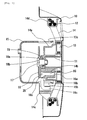
Fig. 1 , a columnarratchet attachment portion 14a is formed at the center of therope reel 14 so as to protrude in a direction to leave thestarter case 10. A substantially bottomedcylindrical drive pulley 15 is disposed to cover theratchet attachment portion 14a. Thedrive pulley 15 is to transmit the torque of therope reel 14 to the engine when thedrive pulley 15 is attached to the crankshaft of the engine. As shown inFig. 3 and so on, fouropenings 15b are formed circumferentially at an equal interval in a peripheral wall of thedrive pulley 15 so that theopening 15b can engage withratchet members 16 which will be described later. - In addition, two
shaft holes 14b whose axes are parallel to the axis of the aforementioned reel support shaft 11 (the rotation axis of the rope reel 14) are formed in eccentric positions in theratchet attachment portion 14a of therope reel 14. Theratchet members 16 are rotatably supported in the twoshaft holes 14b respectively. Thus, theratchet members 16 are disposed on an inner side of thedrive pulley 15. Theratchet members 16 are formed so that, when theratchet members 16 engage with thedrive pulley 15, the rotation of therope reel 14 in an engine start direction can be transmitted to the drivepulley 15. - As shown in
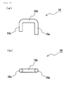
Fig. 2 , eachratchet member 16 is a wire-like member having a circular shape in section and made of a raw material such as steel. Theratchet member 16 consists of arotary shaft portion 16a which is inserted into theaforementioned shaft hole 14b, anarm portion 16b in which an open-end portion side of therotary shaft portion 16a is bent substantially at a right angle, and adistal end portion 16c in which a distal end of thearm portion 16b is bent in parallel with therotary shaft portion 16a. Theratchet member 16 is a substantially U-shaped member in which thedistal end portion 16c is formed to be slightly shorter than therotary shaft portion 16a. - The
ratchet member 16 can rotate in a predetermined range around therotary shaft portion 16a as shown inFig. 4 . To describe in detail, theratchet member 16 can rotate between a reception position shown inFig. 4(a) and an engagement position shown inFig. 4(c) . - In the reception position shown in
Fig. 4(a) , the rotation of theratchet member 16 is limited because thedistal end portion 16c abuts against an inner side of anotch 14e provided in theratchet attachment portion 14a (seeFig. 3 ). On the other hand, in the engagement position shown inFig. 4 (c) , the rotation of theratchet member 16 is limited because thedistal end portion 16c abuts against areception portion 14c provided farther in an outer diameter direction than theratchet attachment portion 14a of therope reel 14. - A spring seat is formed near the
shaft hole 14b. Atorsion coil spring 20 retained in the spring seat acts on theratchet member 16 so as to urge theratchet member 16 in a direction to prevent thedistal end portion 16c from protruding in the outer diameter direction of therope reel 14. Thus, theratchet member 16 is urged to the aforementioned reception position in the state where therope reel 14 is not rotating in the engine start direction. - In addition, as shown in
Fig. 1 , acontrol member 18 is attached to an end surface of the aforementionedreel support shaft 11 by aset screw 17. By thecontrol member 18, therope reel 14 is prevented from dropping out from thereel support shaft 11. In thecontrol member 18, ascrew hole 18b which is penetrated by theset screw 17 is formed in acylindrical portion 18a at the center of thecontrol member 18. Afriction spring 19 is attached to the periphery of thecylindrical portion 18a. Thefriction spring 19 fastens thecylindrical portion 18a of thecontrol member 18 from its outer periphery, so that a predetermined frictional force (at least a frictional force which can act against the urging force of the torsion coil spring 20) can be generated between thecylindrical portion 18a and theset screw 17. Thus, friction resistance is given to thecontrol member 18 against thereel support shaft 11 so that thecontrol member 18 can be rotatably attached to thereel support shaft 11. - An
engagement portion 18c which can engage with theratchet member 16 is formed to protrude in the surface of thecontrol member 18 on theratchet member 16 side, as shown inFig. 1 ,Fig. 3 and so on. Theengagement portion 18c is to engage with theratchet member 16 so as to rotate theratchet member 16 in a direction (engagement position) to abut against thereception portion 14c when theratchet member 16 is rotated in accordance with the rotation of therope reel 14. As will be described later, the rotatedratchet member 16 penetrates theopening 15b of thedrive pulley 15 to engage with the edge of theopening 15b, with the result that the torque of therope reel 14 can be transmitted to the drivepulley 15. - Next, description will be made on the operation of the recoil starter according to this embodiment.
- Before the operation of starting the engine, each
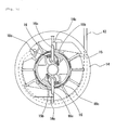
ratchet member 16 is urged to the reception position by the action of thetorsion coil spring 20, and thedistal end portion 16c is disposed to leave thedrive pulley 15, as shown inFig. 3 . - When the
recoil rope 12 is pulled in this state, therope reel 14 rotates so that eachratchet member 16 rotates together with therope reel 14, as shown inFig. 4 (a) . On this occasion, because thecontrol member 18 is attached to thereel support shaft 11 with a predetermined rotation resistance, thecontrol member 18 does not rotate, but thearm portion 16b of theratchet member 16 abuts against theengagement portion 18c of thecontrol member 18, as shown inFig. 4(b) . Then, theratchet member 16 further rotates together with therope reel 14. Thus, thearm portion 16b is thrust against theengagement portion 18c, and thedistal end portion 16c rotates to protrude in the outer diameter direction. When an innerperipheral surface 15a of thedrive pulley 15 is located on an outer peripheral side of theratchet member 16 at this time, thedistal end portion 16c of theratchet member 16 is rotated to reach theopening 15b of thedrive pulley 15 while sliding on the innerperipheral surface 15a of thedrive pulley 15. - When the
distal end portion 16c of theratchet member 16 rotates to reach theopening 15b of thedrive pulley 15, thedistal end portion 16c of theratchet member 16 penetrates theopening 15b of thedrive pulley 15, and thedistal end portion 16c abuts against thereception portion 14c formed in the outer diameter direction of therope reel 14, as shown inFig. 4(c) . Thus, the rotation of theratchet member 16 is stopped so that the engagement position shown inFig. 5 is kept. Then, theratchet member 16 also rotates together with therope reel 14 while keeping the engagement position. On this occasion, due to the engagement between the edge of theopening 15b of thedrive pulley 15 and thearm portion 16b of theratchet member 16, thedrive pulley 15 also rotates together with therope reel 14. Thus, the engine can be started. - When the
rope reel 14 rotates in the state shown inFig. 4 (c) , thecontrol member 18 is pressed onto theratchet member 16 through theengagement portion 18c. Thus, thecontrol member 18 is rotated in the engine start direction together with therope reel 14 against the rotation resistance generated by thefriction spring 19. - After the start of the engine, the
drive pulley 15 rotates in concert with the rotation of the crankshaft so that therope reel 14 rotates reversely relatively. Thus, theratchet member 16 is pushed back to the edge of theopening 15b of thedrive pulley 15, so that theratchet member 16 rotates toward the reception position. As a result, theratchet member 16 leaves thedrive pulley 15. Accordingly, theratchet member 16 is formed to prevent the rotation of the engine from being transmitted to therope reel 14. - Even if the engine is not started, the
rope reel 14 can be rotated in the opposite direction so as to rewind therecoil rope 12 on therope reel 14 due to the torque accumulated in therecoil spring 13 when therecoil rope 12 is loosened. On this occasion, theratchet member 16 also rotates in the opposite direction together with therope reel 14 so that thearm portion 16b of theratchet member 16 can be pushed back by theengagement portion 18c of thecontrol member 18. Thus, theratchet member 16 further rotates to the reception position by the action of thetorsion coil spring 20. - In this manner, according to this embodiment, processing on the end surface of each
ratchet member 16 and so on is not required. Therefore, theratchet member 16 can be manufactured only by a bending process so that theratchet member 16 can be manufactured at a low cost. - In addition, since the
distal end portion 16c of theratchet member 16 is a wire-like member having a circular shape in section and provided in parallel with the rotation axis of the rope reel 14 (the reel support shaft 11), the curved surface in the axially side surface of thedistal end portion 16c abuts against the innerperipheral surface 15a of thedrive pulley 15 so that the sliding resistance when thedistal end portion 16c slides on the innerperipheral surface 15a of thedrive pulley 15 can be formed to be small. That is, when theratchet member 16 rotates to protrude in the outer diameter direction, thedistal end portion 16c can slide on the innerperipheral surface 15a of thedrive pulley 15 smoothly. Thus, theratchet member 16 and thedrive pulley 15 can be prevented from locking on each other. - In addition, the
opening 15b which can be penetrated by thedistal end portion 16c of theratchet member 16 rotated to protrude in the outer diameter direction is formed in thedrive pulley 15, and thedistal end portion 16c penetrating theopening 15b is supported on thereception portion 14c formed in therope reel 14. Thus, when therope reel 14 rotates in the engine start direction, theratchet member 16 which has one end (therotary shaft portion 16a) supported in theshaft hole 14b and the other end (thedistal end portion 16c) supported on thereception portion 14c rotates together with therope reel 14. On this occasion, since theratchet member 16 penetrates theopening 15b of thedrive pulley 15, the torque of therope reel 14 is transmitted to the drivepulley 15 through theopening 15b. - According to this embodiment, the
distal end portion 16c of theratchet member 16 supported on thereception portion 14c is provided as a shaft parallel with the rotation axis of the rope reel 14 (the reel support shaft 11). Thus, even if thedistal end portion 16c is formed to be not large in the radial direction, thedistal end portion 16c and thereception portion 14c can be brought into engagement in a wide range. Thus, the load at the time of start of the engine can be dispersed to enhance the load-bearing property, and reduction of the size in the radial direction can be achieved. - Next, description will be made about a second embodiment of the invention. This embodiment is characterized in the point that the
drive pulley 15 is formed into a different shape. That is, thedrive pulley 15 allows theratchet member 16 to engage with theopening 15b in the first embodiment whereas thedrive pulley 15 allows theratchet member 16 to engage with arecess portion 15c provided in an inner peripheral wall in the second embodiment. - In the recoil starter according to this embodiment, as shown in
Fig. 6 , areel support shaft 11 is formed on an inner side surface of astarter case 10 formed to receive main constituents of the recoil starter and cover a side surface portion of an engine, so that thereel support shaft 11 can face a crankshaft of the engine. Arope reel 14 on which arecoil rope 12 is wound is rotatably attached to an outer periphery of thereel support shaft 11. - As shown in
Fig. 6 andFig. 7 , therecoil rope 12 is wound around areel portion 14d formed in an outer periphery of therope reel 14, and has one end fixed to therope reel 14 and the other end extracted to the outside of thestarter case 10 from an opening (not shown) formed in thestarter case 10. Therope reel 14 is formed so as to be driven and rotated around thereel support shaft 11 as a rotation axis when the extractedrecoil rope 12 is pulled. - As shown in
Fig. 6 , arecoil spring 13 for rotating therope reel 14 rotated by the pull of therecoil rope 12 in an opposite direction so as to rewind the extractedrecoil rope 12 on therope reel 14 is disposed between therope reel 14 and thereel support shaft 11. Therecoil spring 13 has one end fixed to therope reel 14 and the other end fixed to thereel support shaft 11. Therecoil spring 13 operates as follows. That is, when therecoil rope 12 is operated and pulled to rotate therope reel 14, torque is accumulated in therecoil spring 13. As soon as therecoil rope 12 is released, therope reel 14 is rotated in the opposite direction due to the torque accumulated in therecoil spring 13 so that therecoil rope 12 extracted to the outside of thestarter case 10 is rewound on therope reel 14. - As shown in
Fig. 6 , a columnarratchet attachment portion 14a is formed at the center of therope reel 14 so as to protrude in a direction to leave thestarter case 10. A substantially bottomedcylindrical drive pulley 15 is disposed to cover theratchet attachment portion 14a. Thedrive pulley 15 is to transmit the torque of therope reel 14 to the engine when thedrive pulley 15 is attached to the crankshaft of the engine. As shown inFig. 7 and so on, fourrecess portions 15c are formed circumferentially at an equal interval in the peripheral wall of thedrive pulley 15. When ratchetmembers 16 which will be described later rotate to protrude in the outer diameter direction, therecess portions 15c can receivedistal end portions 16c of theratchet members 16. - In addition, two
shaft holes 14b whose axes are parallel to the axis of the aforementioned reel support shaft 11 (the rotation axis of the rope reel 14) are formed in eccentric positions on theratchet attachment portion 14a of therope reel 14. Theratchet members 16 are rotatably supported in the twoshaft holes 14b respectively. Thus, theratchet members 16 are disposed on an inner side of thedrive pulley 15. Theratchet members 16 are formed so that, when theratchet members 16 engage with thedrive pulley 15, the rotation of therope reel 14 in an engine start direction can be transmitted to the drivepulley 15. - As shown in
Fig. 2 , eachratchet member 16 is a wire-like member having a circular shape in section and made of a raw material such as steel. Theratchet member 16 consists of arotary shaft portion 16a which is inserted into theaforementioned shaft hole 14b, anarm portion 16b in which an open-end portion side of therotary shaft portion 16a is bent substantially at a right angle, and adistal end portion 16c in which a distal end of thearm portion 16b is bent in parallel with therotary shaft portion 16a. Theratchet member 16 is a substantially U-shaped member in which thedistal end portion 16c is formed to be slightly shorter than therotary shaft portion 16a. - The
ratchet member 16 can rotate in a predetermined range around therotary shaft portion 16a, as shown inFig. 8 . To describe in detail, theratchet member 16 can rotate between a reception position shown inFig. 8(a) and an engagement position shown inFig. 8(c) . - In the reception position shown in
Fig. 8(a) , the rotation of theratchet member 16 is limited because thedistal end portion 16c abuts against an inner side of anotch 14e provided in theratchet attachment portion 14a (seeFig. 7 ). On the other hand, in the engagement position shown inFig. 8 (c) , the rotation of theratchet member 16 is limited because thedistal end portion 16c abuts against therecess portion 15c of thedrive pulley 15. - A spring seat is formed near the
shaft hole 14b. Atorsion coil spring 20 retained in the spring seat acts on theratchet member 16 so as to urge theratchet member 16 in a direction to prevent thedistal end portion 16c from protruding in the outer diameter direction of therope reel 14. Thus, theratchet member 16 is urged to the aforementioned reception position in the state where therope reel 14 is not rotating in the engine start direction. - In addition, as shown in
Fig. 6 , acontrol member 18 is attached to an end surface of the aforementionedreel support shaft 11 by aset screw 17. By thecontrol member 18, therope reel 14 can be prevented from dropping out from thereel support shaft 11. In thecontrol member 18, ascrew hole 18b which is penetrated by theset screw 17 is formed in acylindrical portion 18a at the center of thecontrol member 18. Afriction spring 19 is attached to the periphery of thecylindrical portion 18a. Thefriction spring 19 fastens thecylindrical portion 18a of thecontrol member 18 from its outer periphery, so that a predetermined frictional force (at least a frictional force which can act against the urging force of the torsion coil spring 20) can be generated between thecylindrical portion 18a and theset screw 17. Thus, friction resistance is given to thecontrol member 18 against thereel support shaft 11 so that thecontrol member 18 can be rotatably attached to thereel support shaft 11. - An
engagement portion 18c which can engage with theratchet member 16 is formed to protrude in the surface of thecontrol member 18 on theratchet member 16 side, as shown inFig. 6 ,Fig. 7 and so on. Theengagement portion 18c is to engage with theratchet member 16 so as to rotate theratchet member 16 in a direction (engagement position) to abut against therecess portion 15c of thedrive pulley 15 when theratchet member 16 is rotated in accordance with the rotation of therope reel 14. As will be described later, the rotatedratchet member 16 engages with therecess portion 15c of thedrive pulley 15, with the result that the torque of therope reel 14 can be transmitted to the drivepulley 15. - Next, description will be made on the operation of the recoil starter according to this embodiment.
- Before the operation of starting the engine, each
ratchet member 16 is urged to the reception position by the action of thetorsion coil spring 20, and thedistal end portion 16c is disposed to leave thedrive pulley 15, as shown inFig. 7 . - When the
recoil rope 12 is pulled in this state, therope reel 14 rotates and eachratchet member 16 rotates together with therope reel 14, as shown inFig. 8 (a) . On this occasion, since thecontrol member 18 is attached to thereel support shaft 11 with a predetermined rotation resistance, thecontrol member 18 does not rotate, but thearm portion 16b of theratchet member 16 abuts against theengagement portion 18c of thecontrol member 18, as shown inFig. 8(b) . Then, theratchet member 16 further rotates together with therope reel 14. Thus, thearm portion 16b is thrust against theengagement portion 18c, and thedistal end portion 16c rotates to protrude in the outer diameter direction. When the innerperipheral surface 15a of thedrive pulley 15 other than therecess portions 15c is located on an outer peripheral side of theratchet member 16 at this time, thedistal end portion 16c of theratchet member 16 is rotated to reach therecess portion 15c of thedrive pulley 15 while sliding on the innerperipheral surface 15a of thedrive pulley 15. - When the
distal end portion 16c of theratchet member 16 rotates to reach therecess portion 15c of thedrive pulley 15, thedistal end portion 16c of theratchet member 16 engages with therecess portion 15c of thedrive pulley 15, as shown inFig. 8 (c) . As a result, the rotation of theratchet member 16 is stopped so that the engagement position shown inFig. 9 is kept. Then, theratchet member 16 and thedrive pulley 15 rotate together with therope reel 14 while the engagement position is kept. Thus, the engine can be started. - When the
rope reel 14 rotates in the state shown inFig. 8 (c) , thecontrol member 18 is pressed onto theratchet member 16 through theengagement portion 18c. Thus, thecontrol member 18 is rotated in the engine start direction together with therope reel 14 against the rotation resistance generated by thefriction spring 19. - After the start of the engine, the
drive pulley 15 rotates in concert with the rotation of the crankshaft so that therope reel 14 rotates reversely relatively. Thus, theratchet member 16 is pushed back to the edge of therecess portion 15c of thedrive pulley 15, so that theratchet member 16 rotates toward the reception position. As a result, theratchet member 16 leaves thedrive pulley 15. Accordingly, theratchet member 16 is formed to prevent the rotation of the engine from being transmitted to therope reel 14. - Even if the engine is not started, the
rope reel 14 is rotated in the opposite direction so as to rewind therecoil rope 12 on therope reel 14 due to the torque accumulated in therecoil spring 13 when therecoil rope 12 is loosened. On this occasion, theratchet member 16 also rotates in the opposite direction together with therope reel 14 so that thearm portion 16b of theratchet member 16 is pushed back by theengagement portion 18c of thecontrol member 18 and theratchet member 16 further rotates to the reception position by the action of thetorsion coil spring 20. - In this manner, according to this embodiment, processing on the end surface of each
ratchet member 16 and so on is not required. Therefore, theratchet member 16 can be manufactured only by a bending process so that theratchet member 16 can be manufactured at a low cost. - In addition, since the
distal end portion 16c of theratchet member 16 is a wire-like member having a circular shape in section and provided in parallel with the rotation axis of the rope reel 14 (the reel support shaft 11), the curved surface in the axially side surface of thedistal end portion 16c abuts against the innerperipheral surface 15a of thedrive pulley 15 so that the sliding resistance when thedistal end portion 16c slides on the innerperipheral surface 15a of thedrive pulley 15 can be formed to be small. That is, when theratchet member 16 rotates to protrude in the outer diameter direction, thedistal end portion 16c can slide on the innerperipheral surface 15a of thedrive pulley 15 smoothly so that theratchet member 16 and thedrive pulley 15 are prevented from locking on each other in any position except therecess portions 15c. - In addition, each
recess portion 15c for receiving thedistal end portion 16c of theratchet member 16 rotated to protrude in the outer diameter direction is formed in thedrive pulley 15. Thus, when therope reel 14 rotates in the engine start direction, thedistal end portion 16c of theratchet member 16 engages with therecess portion 15c of thedrive pulley 15 so that the torque of therope reel 14 is transmitted to the drivepulley 15 through therecess portion 15c. - According to this embodiment, both the
rotary shaft portion 16a and thedistal end portion 16c of eachratchet member 16 suffering a load are provided in parallel with the rotation axis of the rope reel 14 (the reel support shaft 11). There is therefore no fear that the load is applied in a direction to tilt theratchet member 16 or in a direction to make theratchet member 16 drop out. Thus, theratchet member 16 can be prevented from dropping out. -
Ratchet members 16 in each of which anarm portion 16b is bent at an obtuse angle (e.g. 120 degrees) as shown inFig. 10 may be used in place of theaforementioned ratchet members 16 according to the first embodiment and the second embodiment. - When
such ratchet members 16 are used, eachratchet member 16 can be moved from the reception position to the engagement position with a small operating angle. Thus, the rotation angle of a backlash becomes small so that the rotation of therope reel 14 can be transmitted to the drivepulley 15 efficiently. -
Ratchet members 16 and arope reel 14 as shown inFig. 11 may be used in place of theaforementioned ratchet members 16 and therope reel 14 according to the second embodiment. - The
rope reel 14 according to this second modification is provided withreception portions 14c for receivingdistal end portions 16c of theratchet members 16. In addition, in theratchet members 16 according to the second modification, thedistal end portions 16c are provided to be slightly long enough to be able to touch thereception portions 14c respectively. - Accordingly, as shown in
Fig. 11 , eachratchet member 16 is formed as follows. That is, when thedistal end portion 16c of theratchet member 16 rotates to protrude in the outer diameter direction and engages with thedrive pulley 15, a part of thedistal end portion 16c of theratchet member 16 is supported on thereception portion 14c formed in therope reel 14. Thus, when therope reel 14 rotates in the engine start direction, theratchet member 16 which has one end (therotary shaft portion 16a) supported in theshaft hole 14b and the other end (thedistal end portion 16c) supported on thereception portion 14c rotates together with therope reel 14. On this occasion, the torque of therope reel 14 is transmitted to the drivepulley 15 through therecess portion 15c because thedistal end portion 16c of theratchet member 16 engages with therecess portion 15c of thedrive pulley 15. - As long as
such ratchet members 16 andsuch rope reel 14 are used, even if a load on the engine side is applied to eachratchet member 16 when theratchet member 16 engages with thedrive pulley 15 so as to start the engine, theratchet member 16 can be effectively prevented from tilting because the opposite end portions (therotary shaft portion 16a and thedistal end portion 16c) of theratchet member 16 are supported on therope reel 14. - In the
ratchet member 16 according to the second modification, thearm portion 16b may be bent in an obtuse angle in the same manner as in theratchet member 16 according to the first modification. -
- 10
- starter case
- 11
- reel support shaft
- 12
- recoil rope
- 13
- recoil spring
- 14
- rope reel
- 14a
- ratchet attachment portion
- 14b
- shaft hole
- 14c
- reception portion
- 14d
- reel portion
- 14e
- notch
- 15
- drive pulley
- 15a
- inner peripheral surface
- 15b
- opening
- 15c
- recess portion
- 16
- ratchet member
- 16a
- rotary shaft portion
- 16b
- arm portion
- 16c
- distal end portion
- 17
- set screw
- 18
- control member
- 18a
- cylindrical portion
- 18b
- screw hole
- 18c
- engagement portion
- 19
- friction spring
- 20
- torsion coil spring (urging unit)
Claims (5)
- A recoil starter comprising:a rope reel in which a ratchet attachment portion is provided at the center thereof;a drive pulley which is disposed to cover the ratchet attachment portion;a ratchet member which is attached to the ratchet attachment portion and disposed on an inner side of the drive pulley; anda control member which is attached coaxially with the rope reel so that the control member can rotate with friction resistance given thereto, and which has an engagement portion capable of engaging with the ratchet member; characterized in that:a shaft hole is formed in the ratchet attachment portion and in parallel with a rotation axis of the rope reel;the ratchet member is a wire-like member having a circular shape in section and rotatably attached to the shaft hole, and includes a rotary shaft portion which is inserted into the shaft hole, an arm portion which is extended from the rotary shaft portion and bent substantially at a right angle therewith, and a distal end portion which is extended from the arm portion and bent in parallel with the rotary shaft portion; andthe ratchet member is further arranged so that, when the rope reel rotates in an engine start direction, the arm portion is thrust against the engagement portion of the control member so that the distal end portion is rotated to protrude in an outer diameter direction and the rotated distal end portion engages with the drive pulley so as to transmit torque of the rope reel to the drive pulley.
- A recoil starter according to Claim 1, characterized in that: an opening is formed in the drive pulley so that the distal end portion of the ratchet member rotated to protrude in the outer diameter direction can penetrate the opening.
- A recoil starter according to Claim 1, characterized in that: a recess portion for receiving the distal end portion of the ratchet member rotated to protrude in the outer diameter direction is formed in the drive pulley.
- A recoil starter according to Claim 2 or 3, characterized in that: when the distal end portion of the ratchet member is rotated to protrude in the outer diameter direction to thereby engage with the drive pulley, the distal end portion is supported by a reception portion formed in the rope pulley.
- A recoil starter according to any one of Claims 1 through 4, characterized by further comprising:an urging unit for urging the ratchet member in a direction to prevent the distal end portion from protruding in the outer diameter direction.
Applications Claiming Priority (3)
| Application Number | Priority Date | Filing Date | Title |
|---|---|---|---|
| JP2010268157 | 2010-12-01 | ||
| JP2011194790A JP5836713B2 (en) | 2010-12-01 | 2011-09-07 | Recoil starter |
| PCT/JP2011/006431 WO2012073445A1 (en) | 2010-12-01 | 2011-11-18 | Recoil starter |
Publications (3)
| Publication Number | Publication Date |
|---|---|
| EP2647829A1 true EP2647829A1 (en) | 2013-10-09 |
| EP2647829A4 EP2647829A4 (en) | 2017-09-06 |
| EP2647829B1 EP2647829B1 (en) | 2019-04-03 |
Family
ID=46171419
Family Applications (1)
| Application Number | Title | Priority Date | Filing Date |
|---|---|---|---|
| EP11844680.6A Active EP2647829B1 (en) | 2010-12-01 | 2011-11-18 | Recoil starter |
Country Status (6)
| Country | Link |
|---|---|
| US (1) | US20130247860A1 (en) |
| EP (1) | EP2647829B1 (en) |
| JP (1) | JP5836713B2 (en) |
| KR (1) | KR101877749B1 (en) |
| CN (1) | CN103237983B (en) |
| WO (1) | WO2012073445A1 (en) |
Cited By (1)
| Publication number | Priority date | Publication date | Assignee | Title |
|---|---|---|---|---|
| US11319915B2 (en) | 2020-06-11 | 2022-05-03 | Kohler Co. | Engine system, and method of starting the engine |
Families Citing this family (8)
| Publication number | Priority date | Publication date | Assignee | Title |
|---|---|---|---|---|
| JP6029473B2 (en) * | 2013-01-07 | 2016-11-24 | スターテング工業株式会社 | Recoil starter |
| JP6509530B2 (en) | 2014-11-19 | 2019-05-08 | スターテング工業株式会社 | Recoil starter |
| KR101674204B1 (en) | 2015-05-06 | 2016-11-08 | 공주대학교 산학협력단 | Automatic starting apparatus using flywheel for small engin |
| KR101693036B1 (en) | 2015-05-21 | 2017-01-04 | 공주대학교 산학협력단 | Automatic starting apparatus for small engin |
| US10134306B2 (en) * | 2016-02-26 | 2018-11-20 | Cae Healthcare Canada Inc. | Apparatus for simulating insertion of an elongated instrument into a structure and medical insertion simulator |
| JP7391357B2 (en) * | 2019-09-19 | 2023-12-05 | スターテング工業株式会社 | recoil starter |
| JP7561377B2 (en) * | 2021-03-19 | 2024-10-04 | 本田技研工業株式会社 | Recoil Starter |
| JP7580767B2 (en) | 2021-05-27 | 2024-11-12 | スターテング工業株式会社 | Recoil Starter |
Family Cites Families (10)
| Publication number | Priority date | Publication date | Assignee | Title |
|---|---|---|---|---|
| JPS61125671U (en) | 1985-01-24 | 1986-08-07 | ||
| SE503356C2 (en) * | 1994-09-02 | 1996-05-28 | Electrolux Ab | Incinerator starter |
| JP2002327666A (en) * | 2001-03-01 | 2002-11-15 | Starting Ind Co Ltd | Starter device |
| US6959680B2 (en) * | 2002-07-24 | 2005-11-01 | Starting Industrial Co., Ltd. | Recoil starter |
| JP3892772B2 (en) * | 2002-07-24 | 2007-03-14 | スターテング工業株式会社 | Recoil starter |
| JP3680052B2 (en) * | 2002-09-26 | 2005-08-10 | 株式会社クボタ | Engine recoil starter |
| JP3902528B2 (en) * | 2002-10-02 | 2007-04-11 | スターテング工業株式会社 | Recoil starter |
| DE102004036109B4 (en) * | 2004-07-08 | 2006-08-03 | BLüCHER GMBH | Rotary tube for activated carbon production and its use |
| JP4376193B2 (en) * | 2005-02-08 | 2009-12-02 | ハスクバーナ・ゼノア株式会社 | Power transmission mechanism between engine starter and engine |
| DE102007020680B4 (en) * | 2007-05-03 | 2016-07-21 | Andreas Stihl Ag & Co. Kg | Internal combustion engine with a starting device |
-
2011
- 2011-09-07 JP JP2011194790A patent/JP5836713B2/en active Active
- 2011-11-18 US US13/989,915 patent/US20130247860A1/en not_active Abandoned
- 2011-11-18 KR KR1020137012537A patent/KR101877749B1/en active Active
- 2011-11-18 EP EP11844680.6A patent/EP2647829B1/en active Active
- 2011-11-18 WO PCT/JP2011/006431 patent/WO2012073445A1/en not_active Ceased
- 2011-11-18 CN CN201180057920.1A patent/CN103237983B/en active Active
Non-Patent Citations (1)
| Title |
|---|
| See references of WO2012073445A1 * |
Cited By (1)
| Publication number | Priority date | Publication date | Assignee | Title |
|---|---|---|---|---|
| US11319915B2 (en) | 2020-06-11 | 2022-05-03 | Kohler Co. | Engine system, and method of starting the engine |
Also Published As
| Publication number | Publication date |
|---|---|
| JP2012132430A (en) | 2012-07-12 |
| CN103237983B (en) | 2015-12-16 |
| CN103237983A (en) | 2013-08-07 |
| EP2647829B1 (en) | 2019-04-03 |
| EP2647829A4 (en) | 2017-09-06 |
| WO2012073445A1 (en) | 2012-06-07 |
| KR20140009187A (en) | 2014-01-22 |
| JP5836713B2 (en) | 2015-12-24 |
| US20130247860A1 (en) | 2013-09-26 |
| KR101877749B1 (en) | 2018-07-13 |
Similar Documents
| Publication | Publication Date | Title |
|---|---|---|
| EP2647829B1 (en) | Recoil starter | |
| EP1413746B1 (en) | Recoil starter | |
| CN110402903B (en) | Torque limiting device for fishing reel and spinning reel | |
| US8166947B2 (en) | Recoil starter | |
| US20180215343A1 (en) | Webbing take-up device | |
| EP3084205B1 (en) | Starting device for an internal combustion engine | |
| JP2016203846A (en) | Webbing rewinding device | |
| EP2299103B1 (en) | Recoil starter | |
| EP2218907A2 (en) | Recoil starter | |
| EP3023629B1 (en) | Recoil starter | |
| JP2008074137A (en) | Webbing winding device | |
| JPH08267367A (en) | Screw tightening device and clutch mechanism | |
| US7571659B2 (en) | Starting apparatus of small-sized engine | |
| CN103161635A (en) | Recoil starter mechanism | |
| US11754029B2 (en) | Recoil starter | |
| EP4234281A1 (en) | Tire chain tightening device | |
| JPH0210296Y2 (en) | ||
| JP2016101793A (en) | Webbing winding device | |
| JP2003250404A (en) | One-way reducer | |
| WO2010119665A1 (en) | Small engine starting device |
Legal Events
| Date | Code | Title | Description |
|---|---|---|---|
| PUAI | Public reference made under article 153(3) epc to a published international application that has entered the european phase |
Free format text: ORIGINAL CODE: 0009012 |
|
| 17P | Request for examination filed |
Effective date: 20130523 |
|
| AK | Designated contracting states |
Kind code of ref document: A1 Designated state(s): AL AT BE BG CH CY CZ DE DK EE ES FI FR GB GR HR HU IE IS IT LI LT LU LV MC MK MT NL NO PL PT RO RS SE SI SK SM TR |
|
| DAX | Request for extension of the european patent (deleted) | ||
| RA4 | Supplementary search report drawn up and despatched (corrected) |
Effective date: 20170809 |
|
| RIC1 | Information provided on ipc code assigned before grant |
Ipc: F02N 3/02 20060101AFI20170803BHEP |
|
| REG | Reference to a national code |
Ref country code: DE Ref legal event code: R079 Ref document number: 602011057834 Country of ref document: DE Free format text: PREVIOUS MAIN CLASS: F02N0003020000 Ipc: F02N0015020000 |
|
| GRAP | Despatch of communication of intention to grant a patent |
Free format text: ORIGINAL CODE: EPIDOSNIGR1 |
|
| STAA | Information on the status of an ep patent application or granted ep patent |
Free format text: STATUS: GRANT OF PATENT IS INTENDED |
|
| RIC1 | Information provided on ipc code assigned before grant |
Ipc: F02N 3/02 20060101ALI20181030BHEP Ipc: F02N 15/02 20060101AFI20181030BHEP |
|
| INTG | Intention to grant announced |
Effective date: 20181123 |
|
| GRAS | Grant fee paid |
Free format text: ORIGINAL CODE: EPIDOSNIGR3 |
|
| GRAA | (expected) grant |
Free format text: ORIGINAL CODE: 0009210 |
|
| STAA | Information on the status of an ep patent application or granted ep patent |
Free format text: STATUS: THE PATENT HAS BEEN GRANTED |
|
| AK | Designated contracting states |
Kind code of ref document: B1 Designated state(s): AL AT BE BG CH CY CZ DE DK EE ES FI FR GB GR HR HU IE IS IT LI LT LU LV MC MK MT NL NO PL PT RO RS SE SI SK SM TR |
|
| REG | Reference to a national code |
Ref country code: GB Ref legal event code: FG4D |
|
| REG | Reference to a national code |
Ref country code: CH Ref legal event code: EP Ref country code: AT Ref legal event code: REF Ref document number: 1116060 Country of ref document: AT Kind code of ref document: T Effective date: 20190415 |
|
| REG | Reference to a national code |
Ref country code: DE Ref legal event code: R096 Ref document number: 602011057834 Country of ref document: DE |
|
| REG | Reference to a national code |
Ref country code: IE Ref legal event code: FG4D |
|
| REG | Reference to a national code |
Ref country code: SE Ref legal event code: TRGR |
|
| REG | Reference to a national code |
Ref country code: NL Ref legal event code: MP Effective date: 20190403 |
|
| REG | Reference to a national code |
Ref country code: LT Ref legal event code: MG4D |
|
| REG | Reference to a national code |
Ref country code: AT Ref legal event code: MK05 Ref document number: 1116060 Country of ref document: AT Kind code of ref document: T Effective date: 20190403 |
|
| PG25 | Lapsed in a contracting state [announced via postgrant information from national office to epo] |
Ref country code: NL Free format text: LAPSE BECAUSE OF FAILURE TO SUBMIT A TRANSLATION OF THE DESCRIPTION OR TO PAY THE FEE WITHIN THE PRESCRIBED TIME-LIMIT Effective date: 20190403 |
|
| PG25 | Lapsed in a contracting state [announced via postgrant information from national office to epo] |
Ref country code: CZ Free format text: LAPSE BECAUSE OF FAILURE TO SUBMIT A TRANSLATION OF THE DESCRIPTION OR TO PAY THE FEE WITHIN THE PRESCRIBED TIME-LIMIT Effective date: 20190403 Ref country code: NO Free format text: LAPSE BECAUSE OF FAILURE TO SUBMIT A TRANSLATION OF THE DESCRIPTION OR TO PAY THE FEE WITHIN THE PRESCRIBED TIME-LIMIT Effective date: 20190703 Ref country code: ES Free format text: LAPSE BECAUSE OF FAILURE TO SUBMIT A TRANSLATION OF THE DESCRIPTION OR TO PAY THE FEE WITHIN THE PRESCRIBED TIME-LIMIT Effective date: 20190403 Ref country code: LT Free format text: LAPSE BECAUSE OF FAILURE TO SUBMIT A TRANSLATION OF THE DESCRIPTION OR TO PAY THE FEE WITHIN THE PRESCRIBED TIME-LIMIT Effective date: 20190403 Ref country code: HR Free format text: LAPSE BECAUSE OF FAILURE TO SUBMIT A TRANSLATION OF THE DESCRIPTION OR TO PAY THE FEE WITHIN THE PRESCRIBED TIME-LIMIT Effective date: 20190403 Ref country code: PT Free format text: LAPSE BECAUSE OF FAILURE TO SUBMIT A TRANSLATION OF THE DESCRIPTION OR TO PAY THE FEE WITHIN THE PRESCRIBED TIME-LIMIT Effective date: 20190803 Ref country code: AL Free format text: LAPSE BECAUSE OF FAILURE TO SUBMIT A TRANSLATION OF THE DESCRIPTION OR TO PAY THE FEE WITHIN THE PRESCRIBED TIME-LIMIT Effective date: 20190403 Ref country code: FI Free format text: LAPSE BECAUSE OF FAILURE TO SUBMIT A TRANSLATION OF THE DESCRIPTION OR TO PAY THE FEE WITHIN THE PRESCRIBED TIME-LIMIT Effective date: 20190403 |
|
| PG25 | Lapsed in a contracting state [announced via postgrant information from national office to epo] |
Ref country code: RS Free format text: LAPSE BECAUSE OF FAILURE TO SUBMIT A TRANSLATION OF THE DESCRIPTION OR TO PAY THE FEE WITHIN THE PRESCRIBED TIME-LIMIT Effective date: 20190403 Ref country code: LV Free format text: LAPSE BECAUSE OF FAILURE TO SUBMIT A TRANSLATION OF THE DESCRIPTION OR TO PAY THE FEE WITHIN THE PRESCRIBED TIME-LIMIT Effective date: 20190403 Ref country code: GR Free format text: LAPSE BECAUSE OF FAILURE TO SUBMIT A TRANSLATION OF THE DESCRIPTION OR TO PAY THE FEE WITHIN THE PRESCRIBED TIME-LIMIT Effective date: 20190704 Ref country code: BG Free format text: LAPSE BECAUSE OF FAILURE TO SUBMIT A TRANSLATION OF THE DESCRIPTION OR TO PAY THE FEE WITHIN THE PRESCRIBED TIME-LIMIT Effective date: 20190703 Ref country code: PL Free format text: LAPSE BECAUSE OF FAILURE TO SUBMIT A TRANSLATION OF THE DESCRIPTION OR TO PAY THE FEE WITHIN THE PRESCRIBED TIME-LIMIT Effective date: 20190403 |
|
| PG25 | Lapsed in a contracting state [announced via postgrant information from national office to epo] |
Ref country code: IS Free format text: LAPSE BECAUSE OF FAILURE TO SUBMIT A TRANSLATION OF THE DESCRIPTION OR TO PAY THE FEE WITHIN THE PRESCRIBED TIME-LIMIT Effective date: 20190803 Ref country code: AT Free format text: LAPSE BECAUSE OF FAILURE TO SUBMIT A TRANSLATION OF THE DESCRIPTION OR TO PAY THE FEE WITHIN THE PRESCRIBED TIME-LIMIT Effective date: 20190403 |
|
| REG | Reference to a national code |
Ref country code: DE Ref legal event code: R097 Ref document number: 602011057834 Country of ref document: DE |
|
| PG25 | Lapsed in a contracting state [announced via postgrant information from national office to epo] |
Ref country code: SK Free format text: LAPSE BECAUSE OF FAILURE TO SUBMIT A TRANSLATION OF THE DESCRIPTION OR TO PAY THE FEE WITHIN THE PRESCRIBED TIME-LIMIT Effective date: 20190403 Ref country code: EE Free format text: LAPSE BECAUSE OF FAILURE TO SUBMIT A TRANSLATION OF THE DESCRIPTION OR TO PAY THE FEE WITHIN THE PRESCRIBED TIME-LIMIT Effective date: 20190403 Ref country code: DK Free format text: LAPSE BECAUSE OF FAILURE TO SUBMIT A TRANSLATION OF THE DESCRIPTION OR TO PAY THE FEE WITHIN THE PRESCRIBED TIME-LIMIT Effective date: 20190403 Ref country code: RO Free format text: LAPSE BECAUSE OF FAILURE TO SUBMIT A TRANSLATION OF THE DESCRIPTION OR TO PAY THE FEE WITHIN THE PRESCRIBED TIME-LIMIT Effective date: 20190403 |
|
| PLBE | No opposition filed within time limit |
Free format text: ORIGINAL CODE: 0009261 |
|
| STAA | Information on the status of an ep patent application or granted ep patent |
Free format text: STATUS: NO OPPOSITION FILED WITHIN TIME LIMIT |
|
| PG25 | Lapsed in a contracting state [announced via postgrant information from national office to epo] |
Ref country code: SM Free format text: LAPSE BECAUSE OF FAILURE TO SUBMIT A TRANSLATION OF THE DESCRIPTION OR TO PAY THE FEE WITHIN THE PRESCRIBED TIME-LIMIT Effective date: 20190403 |
|
| 26N | No opposition filed |
Effective date: 20200106 |
|
| PG25 | Lapsed in a contracting state [announced via postgrant information from national office to epo] |
Ref country code: TR Free format text: LAPSE BECAUSE OF FAILURE TO SUBMIT A TRANSLATION OF THE DESCRIPTION OR TO PAY THE FEE WITHIN THE PRESCRIBED TIME-LIMIT Effective date: 20190403 |
|
| PG25 | Lapsed in a contracting state [announced via postgrant information from national office to epo] |
Ref country code: SI Free format text: LAPSE BECAUSE OF FAILURE TO SUBMIT A TRANSLATION OF THE DESCRIPTION OR TO PAY THE FEE WITHIN THE PRESCRIBED TIME-LIMIT Effective date: 20190403 |
|
| REG | Reference to a national code |
Ref country code: CH Ref legal event code: PL |
|
| PG25 | Lapsed in a contracting state [announced via postgrant information from national office to epo] |
Ref country code: LI Free format text: LAPSE BECAUSE OF NON-PAYMENT OF DUE FEES Effective date: 20191130 Ref country code: MC Free format text: LAPSE BECAUSE OF FAILURE TO SUBMIT A TRANSLATION OF THE DESCRIPTION OR TO PAY THE FEE WITHIN THE PRESCRIBED TIME-LIMIT Effective date: 20190403 Ref country code: LU Free format text: LAPSE BECAUSE OF NON-PAYMENT OF DUE FEES Effective date: 20191118 Ref country code: CH Free format text: LAPSE BECAUSE OF NON-PAYMENT OF DUE FEES Effective date: 20191130 |
|
| REG | Reference to a national code |
Ref country code: BE Ref legal event code: MM Effective date: 20191130 |
|
| GBPC | Gb: european patent ceased through non-payment of renewal fee |
Effective date: 20191118 |
|
| PG25 | Lapsed in a contracting state [announced via postgrant information from national office to epo] |
Ref country code: GB Free format text: LAPSE BECAUSE OF NON-PAYMENT OF DUE FEES Effective date: 20191118 Ref country code: IE Free format text: LAPSE BECAUSE OF NON-PAYMENT OF DUE FEES Effective date: 20191118 Ref country code: FR Free format text: LAPSE BECAUSE OF NON-PAYMENT OF DUE FEES Effective date: 20191130 |
|
| PG25 | Lapsed in a contracting state [announced via postgrant information from national office to epo] |
Ref country code: BE Free format text: LAPSE BECAUSE OF NON-PAYMENT OF DUE FEES Effective date: 20191130 |
|
| PG25 | Lapsed in a contracting state [announced via postgrant information from national office to epo] |
Ref country code: CY Free format text: LAPSE BECAUSE OF FAILURE TO SUBMIT A TRANSLATION OF THE DESCRIPTION OR TO PAY THE FEE WITHIN THE PRESCRIBED TIME-LIMIT Effective date: 20190403 |
|
| PG25 | Lapsed in a contracting state [announced via postgrant information from national office to epo] |
Ref country code: HU Free format text: LAPSE BECAUSE OF FAILURE TO SUBMIT A TRANSLATION OF THE DESCRIPTION OR TO PAY THE FEE WITHIN THE PRESCRIBED TIME-LIMIT; INVALID AB INITIO Effective date: 20111118 Ref country code: MT Free format text: LAPSE BECAUSE OF FAILURE TO SUBMIT A TRANSLATION OF THE DESCRIPTION OR TO PAY THE FEE WITHIN THE PRESCRIBED TIME-LIMIT Effective date: 20190403 |
|
| PG25 | Lapsed in a contracting state [announced via postgrant information from national office to epo] |
Ref country code: MK Free format text: LAPSE BECAUSE OF FAILURE TO SUBMIT A TRANSLATION OF THE DESCRIPTION OR TO PAY THE FEE WITHIN THE PRESCRIBED TIME-LIMIT Effective date: 20190403 |
|
| PGFP | Annual fee paid to national office [announced via postgrant information from national office to epo] |
Ref country code: DE Payment date: 20251119 Year of fee payment: 15 |
|
| PGFP | Annual fee paid to national office [announced via postgrant information from national office to epo] |
Ref country code: IT Payment date: 20251125 Year of fee payment: 15 |
|
| PGFP | Annual fee paid to national office [announced via postgrant information from national office to epo] |
Ref country code: SE Payment date: 20251119 Year of fee payment: 15 |