EP2647820A1 - Rationality diagnostic device for alcohol concentration sensors - Google Patents
Rationality diagnostic device for alcohol concentration sensors Download PDFInfo
- Publication number
- EP2647820A1 EP2647820A1 EP10857098.7A EP10857098A EP2647820A1 EP 2647820 A1 EP2647820 A1 EP 2647820A1 EP 10857098 A EP10857098 A EP 10857098A EP 2647820 A1 EP2647820 A1 EP 2647820A1
- Authority
- EP
- European Patent Office
- Prior art keywords
- sensor
- output value
- remaining fuel
- fuel amount
- rationality
- Prior art date
- Legal status (The legal status is an assumption and is not a legal conclusion. Google has not performed a legal analysis and makes no representation as to the accuracy of the status listed.)
- Granted
Links
Images


Classifications
-
- G—PHYSICS
- G01—MEASURING; TESTING
- G01M—TESTING STATIC OR DYNAMIC BALANCE OF MACHINES OR STRUCTURES; TESTING OF STRUCTURES OR APPARATUS, NOT OTHERWISE PROVIDED FOR
- G01M15/00—Testing of engines
- G01M15/04—Testing internal-combustion engines
-
- F—MECHANICAL ENGINEERING; LIGHTING; HEATING; WEAPONS; BLASTING
- F02—COMBUSTION ENGINES; HOT-GAS OR COMBUSTION-PRODUCT ENGINE PLANTS
- F02D—CONTROLLING COMBUSTION ENGINES
- F02D19/00—Controlling engines characterised by their use of non-liquid fuels, pluralities of fuels, or non-fuel substances added to the combustible mixtures
- F02D19/06—Controlling engines characterised by their use of non-liquid fuels, pluralities of fuels, or non-fuel substances added to the combustible mixtures peculiar to engines working with pluralities of fuels, e.g. alternatively with light and heavy fuel oil, other than engines indifferent to the fuel consumed
- F02D19/0626—Measuring or estimating parameters related to the fuel supply system
- F02D19/0628—Determining the fuel pressure, temperature or flow, the fuel tank fill level or a valve position
-
- F—MECHANICAL ENGINEERING; LIGHTING; HEATING; WEAPONS; BLASTING
- F02—COMBUSTION ENGINES; HOT-GAS OR COMBUSTION-PRODUCT ENGINE PLANTS
- F02D—CONTROLLING COMBUSTION ENGINES
- F02D19/00—Controlling engines characterised by their use of non-liquid fuels, pluralities of fuels, or non-fuel substances added to the combustible mixtures
- F02D19/06—Controlling engines characterised by their use of non-liquid fuels, pluralities of fuels, or non-fuel substances added to the combustible mixtures peculiar to engines working with pluralities of fuels, e.g. alternatively with light and heavy fuel oil, other than engines indifferent to the fuel consumed
- F02D19/0623—Failure diagnosis or prevention; Safety measures; Testing
-
- F—MECHANICAL ENGINEERING; LIGHTING; HEATING; WEAPONS; BLASTING
- F02—COMBUSTION ENGINES; HOT-GAS OR COMBUSTION-PRODUCT ENGINE PLANTS
- F02D—CONTROLLING COMBUSTION ENGINES
- F02D19/00—Controlling engines characterised by their use of non-liquid fuels, pluralities of fuels, or non-fuel substances added to the combustible mixtures
- F02D19/06—Controlling engines characterised by their use of non-liquid fuels, pluralities of fuels, or non-fuel substances added to the combustible mixtures peculiar to engines working with pluralities of fuels, e.g. alternatively with light and heavy fuel oil, other than engines indifferent to the fuel consumed
- F02D19/0626—Measuring or estimating parameters related to the fuel supply system
- F02D19/0634—Determining a density, viscosity, composition or concentration
-
- F—MECHANICAL ENGINEERING; LIGHTING; HEATING; WEAPONS; BLASTING
- F02—COMBUSTION ENGINES; HOT-GAS OR COMBUSTION-PRODUCT ENGINE PLANTS
- F02D—CONTROLLING COMBUSTION ENGINES
- F02D19/00—Controlling engines characterised by their use of non-liquid fuels, pluralities of fuels, or non-fuel substances added to the combustible mixtures
- F02D19/06—Controlling engines characterised by their use of non-liquid fuels, pluralities of fuels, or non-fuel substances added to the combustible mixtures peculiar to engines working with pluralities of fuels, e.g. alternatively with light and heavy fuel oil, other than engines indifferent to the fuel consumed
- F02D19/0663—Details on the fuel supply system, e.g. tanks, valves, pipes, pumps, rails, injectors or mixers
- F02D19/0665—Tanks, e.g. multiple tanks
-
- F—MECHANICAL ENGINEERING; LIGHTING; HEATING; WEAPONS; BLASTING
- F02—COMBUSTION ENGINES; HOT-GAS OR COMBUSTION-PRODUCT ENGINE PLANTS
- F02D—CONTROLLING COMBUSTION ENGINES
- F02D19/00—Controlling engines characterised by their use of non-liquid fuels, pluralities of fuels, or non-fuel substances added to the combustible mixtures
- F02D19/06—Controlling engines characterised by their use of non-liquid fuels, pluralities of fuels, or non-fuel substances added to the combustible mixtures peculiar to engines working with pluralities of fuels, e.g. alternatively with light and heavy fuel oil, other than engines indifferent to the fuel consumed
- F02D19/08—Controlling engines characterised by their use of non-liquid fuels, pluralities of fuels, or non-fuel substances added to the combustible mixtures peculiar to engines working with pluralities of fuels, e.g. alternatively with light and heavy fuel oil, other than engines indifferent to the fuel consumed simultaneously using pluralities of fuels
- F02D19/082—Premixed fuels, i.e. emulsions or blends
- F02D19/084—Blends of gasoline and alcohols, e.g. E85
-
- F—MECHANICAL ENGINEERING; LIGHTING; HEATING; WEAPONS; BLASTING
- F02—COMBUSTION ENGINES; HOT-GAS OR COMBUSTION-PRODUCT ENGINE PLANTS
- F02D—CONTROLLING COMBUSTION ENGINES
- F02D41/00—Electrical control of supply of combustible mixture or its constituents
- F02D41/22—Safety or indicating devices for abnormal conditions
- F02D41/222—Safety or indicating devices for abnormal conditions relating to the failure of sensors or parameter detection devices
-
- G—PHYSICS
- G01—MEASURING; TESTING
- G01F—MEASURING VOLUME, VOLUME FLOW, MASS FLOW OR LIQUID LEVEL; METERING BY VOLUME
- G01F23/00—Indicating or measuring liquid level or level of fluent solid material, e.g. indicating in terms of volume or indicating by means of an alarm
- G01F23/22—Indicating or measuring liquid level or level of fluent solid material, e.g. indicating in terms of volume or indicating by means of an alarm by measuring physical variables, other than linear dimensions, pressure or weight, dependent on the level to be measured, e.g. by difference of heat transfer of steam or water
- G01F23/26—Indicating or measuring liquid level or level of fluent solid material, e.g. indicating in terms of volume or indicating by means of an alarm by measuring physical variables, other than linear dimensions, pressure or weight, dependent on the level to be measured, e.g. by difference of heat transfer of steam or water by measuring variations of capacity or inductance of capacitors or inductors arising from the presence of liquid or fluent solid material in the electric or electromagnetic fields
- G01F23/263—Indicating or measuring liquid level or level of fluent solid material, e.g. indicating in terms of volume or indicating by means of an alarm by measuring physical variables, other than linear dimensions, pressure or weight, dependent on the level to be measured, e.g. by difference of heat transfer of steam or water by measuring variations of capacity or inductance of capacitors or inductors arising from the presence of liquid or fluent solid material in the electric or electromagnetic fields by measuring variations in capacitance of capacitors
-
- F—MECHANICAL ENGINEERING; LIGHTING; HEATING; WEAPONS; BLASTING
- F02—COMBUSTION ENGINES; HOT-GAS OR COMBUSTION-PRODUCT ENGINE PLANTS
- F02D—CONTROLLING COMBUSTION ENGINES
- F02D2200/00—Input parameters for engine control
- F02D2200/02—Input parameters for engine control the parameters being related to the engine
- F02D2200/06—Fuel or fuel supply system parameters
- F02D2200/0611—Fuel type, fuel composition or fuel quality
-
- Y—GENERAL TAGGING OF NEW TECHNOLOGICAL DEVELOPMENTS; GENERAL TAGGING OF CROSS-SECTIONAL TECHNOLOGIES SPANNING OVER SEVERAL SECTIONS OF THE IPC; TECHNICAL SUBJECTS COVERED BY FORMER USPC CROSS-REFERENCE ART COLLECTIONS [XRACs] AND DIGESTS
- Y02—TECHNOLOGIES OR APPLICATIONS FOR MITIGATION OR ADAPTATION AGAINST CLIMATE CHANGE
- Y02T—CLIMATE CHANGE MITIGATION TECHNOLOGIES RELATED TO TRANSPORTATION
- Y02T10/00—Road transport of goods or passengers
- Y02T10/10—Internal combustion engine [ICE] based vehicles
- Y02T10/30—Use of alternative fuels, e.g. biofuels
-
- Y—GENERAL TAGGING OF NEW TECHNOLOGICAL DEVELOPMENTS; GENERAL TAGGING OF CROSS-SECTIONAL TECHNOLOGIES SPANNING OVER SEVERAL SECTIONS OF THE IPC; TECHNICAL SUBJECTS COVERED BY FORMER USPC CROSS-REFERENCE ART COLLECTIONS [XRACs] AND DIGESTS
- Y02—TECHNOLOGIES OR APPLICATIONS FOR MITIGATION OR ADAPTATION AGAINST CLIMATE CHANGE
- Y02T—CLIMATE CHANGE MITIGATION TECHNOLOGIES RELATED TO TRANSPORTATION
- Y02T10/00—Road transport of goods or passengers
- Y02T10/10—Internal combustion engine [ICE] based vehicles
- Y02T10/40—Engine management systems
Definitions
- the present invention relates to a rationality diagnostic device that diagnoses the rationality of an alcohol concentration sensor that measures the alcohol concentration of fuel used in an internal combustion engine.
- an FFV flexible fuel vehicle
- An internal combustion engine for the FFV includes an alcohol concentration sensor that determines the alcohol concentration of an employed fuel.
- An output value of the alcohol concentration sensor is used as a parameter for air-fuel ratio control of the internal combustion engine. This not only acquires desired torque but also ensures satisfactory emissions performance without regard to the ethanol concentration of the employed fuel.
- the alcohol concentration sensor for the FFV internal combustion engine plays an important role to ensure the performance of the internal combustion engine.
- the other sensors there is no assurance that the alcohol concentration sensor properly functions at all times. Wire breakage, short-circuiting, sensor element deterioration, or other abnormality may occur in the alcohol concentration sensor. If, in the event of such abnormality, the output value of the alcohol concentration sensor is used to control the internal combustion engine, then an operation appropriate for the alcohol concentration of the employed fuel cannot be performed. This causes the deterioration of internal combustion engine performance such as emissions performance and fuel efficiency.
- Japanese Patent No. 4477644 determines the difference between a target air-fuel ratio and an actual air-fuel ratio obtained when a fuel injection amount is adjusted in accordance with the target air-fuel ratio, and diagnoses, in accordance with the determined difference, whether or not the alcohol concentration sensor is abnormal.
- the output value of the alcohol concentration sensor is highly reliable, the actual air-fuel ratio should be in agreement with or close to the target air-fuel ratio. Therefore, if the actual air-fuel ratio significantly differs from the target air-fuel ratio, it is probable that the reliability of the output value of the alcohol concentration sensor is low.
- An alternative method for diagnosing the rationality of the alcohol concentration sensor would be to prepare two alcohol concentration sensors that generate the same output when no abnormality exists, and compare the output values of the alcohol concentration sensors. If the alcohol concentration sensors generate different output values or the difference between their output values is greater than a threshold value when the alcohol concentration of the employed fuel is changed, this method makes it possible to conclude that the alcohol concentration sensors are no longer rational.
- the alcohol concentration of the fuel employed for the FFV internal combustion engine changes only when it is fueled. Therefore, even if an alcohol concentration sensor abnormality occurs in such a manner as to decrease the reliability of the sensor output value, such an abnormality cannot be detected until a refueling is performed later. Further, if the fuel added at the time of refueling has the same alcohol concentration as the fuel remaining in a fuel tank, the output values of the alcohol concentration sensors remain unchanged. Therefore, the alcohol concentration sensor abnormality still cannot be detected.
- the conventionally proposed technology for diagnosing the rationality of the alcohol concentration sensor is not adequately capable of diagnosing the rationality of the alcohol concentration sensor properly and easily.
- An object of the present invention is to properly and easily diagnose the rationality of an alcohol concentration sensor that measures the alcohol concentration of fuel used in an internal combustion engine. To achieve the above object, the present invention provides a below-described rationality diagnostic device for an alcohol concentration sensor.
- the rationality diagnostic device for an alcohol concentration sensor which is provided by the present invention, includes a capacitance-type remaining fuel amount sensor as the remaining fuel amount sensor to be disposed in a fuel tank.
- the output characteristics of the capacitance-type remaining fuel amount sensor are such that its output value is determined in accordance with the amount of fuel remaining in the fuel tank and the alcohol concentration of the fuel.
- the rationality diagnostic device corrects the output value of the remaining fuel amount sensor in accordance with the output value of the alcohol concentration sensor. If the rationality of the alcohol concentration sensor is maintained, the corrected output value of the remaining fuel amount sensor should properly represent the amount of fuel remaining in the fuel tank.
- the rationality diagnostic device verifies the accuracy of the corrected output value of the remaining fuel amount sensor to judge whether the rationality of the alcohol concentration sensor is maintained.
- Verifying the accuracy of the corrected output value of the remaining fuel amount sensor is extremely easier than verifying the accuracy of the output value of the alcohol concentration sensor. The reason is that it is not difficult to prepare a standard for verification as the corrected output value of the remaining fuel amount sensor is associated with a remaining fuel amount that can be measured by various well-known means. Therefore, the rationality diagnostic device can easily diagnose the rationality of the alcohol concentration sensor. In addition, the rationality diagnostic device can make a diagnosis when the output value of the remaining fuel amount sensor and the output value of the alcohol concentration sensor are available. Consequently, the rationality diagnostic device can quickly diagnose the rationality of the alcohol concentration sensor.
- the rationality of the alcohol concentration sensor could be judged to be lost no matter whether the alcohol concentration sensor is normal.
- an abnormality in the alcohol concentration sensor should be found without fail in order to ensure the emissions performance of the internal combustion engine.
- the rationality diagnostic device makes it possible to surely prevent an erroneous judgment from being formulated to conclude that the rationality is maintained in a situation where the rationality of the alcohol concentration sensor is lost due to its abnormality or fault.
- the following methods may be employed to verify the accuracy of the corrected output value of the remaining fuel amount sensor.
- a first method calculates the remaining fuel amount from the corrected output value of the remaining fuel amount sensor when the fuel tank is in a particular known state concerning the remaining fuel amount. The first method then compares the calculated remaining fuel amount against a known remaining fuel amount in the particular state, and verifies the accuracy of the output value of the remaining fuel amount sensor in accordance with the result of comparison. If the calculated remaining fuel amount agrees with the known remaining fuel amount or the difference between them is not greater than a threshold value, the first method makes it possible to conclude that the accuracy of the corrected output value of the remaining fuel amount sensor is acceptable. In such an instance, a diagnosis is made that the rationality of the alcohol concentration sensor is maintained.
- a second method not only calculates the remaining fuel amount from the corrected output value of a first remaining fuel amount sensor, but also measures the remaining fuel amount with a second remaining fuel amount sensor whose output value is not dependent on alcohol concentration. The second method then compares the calculated remaining fuel amount against the value measured by the second remaining fuel amount sensor, and verifies the accuracy of the corrected output value of the first remaining fuel sensor in accordance with the result of comparison. If the calculated remaining fuel amount agrees with the value measured by the second remaining fuel amount sensor or the difference between them is not greater than a threshold value, the second method makes it possible to conclude that the accuracy of the corrected output value of the first remaining fuel amount sensor is acceptable.
- a third method not only calculates the change in the remaining fuel amount during a predetermined period in accordance with the corrected output value of the remaining fuel amount sensor, but also calculates the amount of fuel consumption during the predetermined period in accordance with the amount of fuel injected from an injector.
- the third method compares the calculated change in the remaining fuel amount against the calculated amount of fuel consumption, and verifies the accuracy of the corrected output value of the remaining fuel amount sensor in accordance with the result of comparison. If the calculated change in the remaining fuel amount agrees with the calculated amount of fuel consumption or the difference between them is not greater than a threshold value, the third method makes it possible to conclude that the accuracy of the corrected output value of the remaining fuel amount sensor is acceptable.
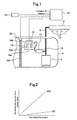
- FIG. 1 is a schematic diagram illustrating the configuration of a fuel supply system for an internal combustion engine that includes the ethanol concentration sensor rationality diagnostic device according to the present embodiment.
- the fuel supply system shown in FIG. 1 includes the ethanol concentration sensor 16, which is disposed in a fuel tank 2. It should be noted, however, that the ethanol concentration sensor 16 is not directly immersed in the fuel stored in the fuel tank 2, but is placed in a fuel container 18 provided in the fuel tank 2. The top of the fuel container 18 is open. The bottom of the fuel container 18 is provided with a fuel outlet 18a that discharges the fuel trapped inside the fuel container 18.
- the ethanol concentration sensor 16 according to the present embodiment is a capacitance-type sensor whose electrode section 16a is completely housed in the fuel container 18.
- the fuel container 18 is connected to the leading end of a return flow path 12.
- the return flow path 12 branches off from a main flow path 6 that connects a fuel pump 4, which draws and pressurizes the fuel in the fuel tank 2, to a delivery pipe 8, which distributes the fuel to an injector 10 of each cylinder.
- a pressure regulator 14 is installed in the middle of the return flow path 12. The pressure regulator 14 is a valve that adjusts the pressure applied to the fuel in the main flow path 6. When the pressure regulator 14 opens, part of the pressurized fuel returns to the fuel tank 2 through the return flow path 12. In this instance, the fuel discharged from the return flow path 12 is introduced into the fuel container 18.
- the electrode section 16a of the ethanol concentration sensor 16 is then immersed in the fuel so that the ethanol concentration sensor 16 can measure the concentration of ethanol.
- the hole diameter of the fuel outlet 18a is designed so that the flow rate of the fuel discharged from the fuel outlet 18a does not exceed the flow rate of the fuel introduced from the return flow path 12.
- a remaining fuel amount sensor 22 is disposed in the fuel tank 2.
- the remaining fuel amount sensor 22 is a capacitance-type sensor whose electrode section 22a is extended from the ceiling of the fuel tank 2 to its bottom.
- the remaining fuel amount sensor 22, which is a capacitance-type sensor has such output characteristics that its output value is determined by the amount of fuel remaining in the fuel tank 2 and the ethanol concentration of the fuel as shown in FIG. 2.
- FIG. 2 is a graph illustrating the relationship between a remaining fuel amount and a sensor output value. More specifically, line E0 indicates the relationship between the remaining fuel amount and sensor output value when the ethanol concentration of fuel is 0%, whereas line E85 indicates the relationship between the remaining fuel amount and sensor output value when the ethanol concentration of fuel is 85%.
- the term "remaining fuel amount” represents not the mass of fuel but the volume of fuel.
- the output values of the ethanol concentration sensor 16 and the remaining fuel amount sensor 22 are both loaded into an ECU 20, which is a control device for the internal combustion engine.
- the ECU 20 determines the ethanol concentration of an employed fuel from the output value of the ethanol concentration sensor 16.
- the determined ethanol concentration is used as a parameter that determines a fuel injection amount for air-fuel ratio control.
- the determined ethanol concentration is also used during a process that determines the remaining fuel amount from the output value of the remaining fuel amount sensor 22.
- the output value of the remaining fuel amount sensor 22 is affected by both the remaining fuel amount and the ethanol concentration. Therefore, when measuring the remaining fuel amount by using the output value of the remaining fuel amount sensor 22, it is necessary to eliminate an ethanol-concentration-dependent component from the sensor output value.
- the ECU 20 corrects the output value of the remaining fuel amount sensor 22 in accordance with the output value of the ethanol concentration sensor 16, and calculates the remaining fuel amount from the corrected output value of the remaining fuel amount sensor 22.
- the present embodiment includes a liquid level detection switch 24 that is one of the various sensors, placed at a predetermined height in the fuel tank 2, and used to detect the liquid level of fuel stored in the fuel tank 2.
- the liquid level detection switch 24 outputs an ON signal when the liquid level of the fuel in the fuel tank 2 is higher than the switch 24, and outputs an OFF signal when the liquid level is lower than the switch 24.
- the output values of these various sensors inform the ECU 20 of the operating status and operating conditions of the internal combustion engine. In accordance with such information, the ECU 20 controls various actuators concerning the operation of the internal combustion engine.
- the rationality diagnostic device is implemented when the ECU 20 functions as an arithmetic processing unit for the rationality diagnostic device in the above-described fuel supply system configuration.
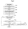
- the ECU 20 executes a rationality judgment routine shown in the flowchart of FIG. 3 .
- the routine is executed at fixed intervals during the operation of the internal combustion engine.
- the output value of the ethanol concentration sensor 16 is acquired in step S102, which is the first step.
- step S104 the output value of the remaining fuel amount sensor 22 is acquired.
- step S106 the output value of the remaining fuel amount sensor 22 is corrected in accordance with the output value of the ethanol concentration sensor 16. For example, a correction coefficient is determined in accordance with the output value of the ethanol concentration sensor 16, and the output value of the remaining fuel amount sensor 22 is multiplied by the correction coefficient.
- the amount of fuel remaining in the fuel tank 2 is calculated from the corrected output value of the remaining fuel amount sensor 22.
- step S110 it is judged whether the signal of the liquid level detection switch 24 has changed from ON to OFF or from OFF to ON.
- the signal changes from ON to OFF when the liquid level drops due to fuel consumption.
- the signal changes from OFF to ON when the liquid level rises due to fueling.
- the liquid level coincides with the height at which the liquid level detection switch 24 is installed.
- the remaining fuel amount at the height of the liquid level detection switch 24 is known and stored in the ECU 20 as the known information for verification.
- the routine does not formulate a rationality judgment until the signal of the liquid level detection switch 24 changes.
- the routine proceeds to step S112 and it is judged whether the ethanol concentration sensor 16 is rational.
- a rationality judgment is formulated by verifying the accuracy of the remaining fuel amount calculated in step S108. In step S112, therefore, the remaining fuel amount calculated in step S108 is compared against the remaining fuel amount that is stored in the ECU 20 for verification purposes.
- step S112 If the comparison result obtained in step S112 indicates that the difference between the calculated remaining fuel amount and the remaining fuel amount for verification is not greater than a predetermined threshold value, the routine concludes that the calculated remaining fuel amount is correct. If the calculated remaining fuel amount is correct, it can be concluded that the output value of the ethanol concentration sensor 16, which is used for the calculation, is reliable. In this instance, the routine proceeds to step S114 and it is concluded that the rationality of the ethanol concentration sensor 16 is maintained.
- the calculated remaining fuel amount is not correct. If the calculated remaining fuel amount is incorrect, it is due to an abnormality in either the ethanol concentration sensor 16 or the remaining fuel amount sensor 22. However, it does not matter which of these sensors 16, 22 is abnormal. To ensure the emissions performance of the internal combustion engine, it is essential that an abnormality in the ethanol concentration sensor 16 be detected without fail. In this case, therefore, no problem occurs even if the ethanol concentration sensor 16 is suspected of abnormality. In either case, there is a certain abnormality in the system. Therefore, even if the ethanol concentration sensor 16 is normal, it is necessary to perform an inspection procedure and a parts replacement procedure. Hence, if the comparison result obtained in step S112 indicates that the calculated remaining fuel amount is incorrect, the routine proceeds to step S116 and it is concluded that the rationality of the ethanol concentration sensor 16 is lost.
- the routine formulates a rationality judgment as described above, it is possible to surely prevent an erroneous judgment from being formulated to conclude that the rationality is maintained in a situation where the rationality of the ethanol concentration sensor 16 is lost due to its abnormality or fault. If a diagnosis is made that the rationality of the ethanol concentration sensor 16 is lost, the ECU 20 uses a malfunction indicator lamp (MIL) or other indicator to notify a driver of the occurrence of abnormality.
- MIL malfunction indicator lamp
- the rationality diagnostic device according to the second embodiment is applied to an ethanol concentration sensor for an internal combustion engine having the fuel supply system shown in FIG. 1 .
- the element identified by the reference numeral 24 in FIG. 1 is a float-type remaining fuel amount sensor in the second embodiment although it is a liquid level detection switch in the first embodiment.
- the second embodiment differs from the first embodiment in the method of judging whether the ethanol concentration sensor 16 is rational.
- the routine shown in the flowchart of FIG. 4 is executed by the ECU 20 in the second embodiment to judge whether the ethanol concentration sensor 16 is rational. Steps performed by the routine will be described below.
- step S202 the output value of the ethanol concentration sensor 16 is acquired in step S202, which is the first step.
- step S204 the output value of the remaining fuel amount sensor 22 is acquired.
- step S206 the output value of the remaining fuel amount sensor 22 is corrected in accordance with the output value of the ethanol concentration sensor 16.
- step S208 the amount of fuel remaining in the fuel tank 2 is calculated from the corrected output value of the remaining fuel amount sensor 22. The steps performed so far are the same as those in the first embodiment.
- step S210 the output value of the float-type remaining fuel amount sensor is loaded into the ECU 20.
- the output value of the float-type remaining fuel amount sensor remains unaffected by ethanol concentration unlike the output value of a capacitance-type sensor.
- the ECU 20 calculates the amount of fuel remaining in the fuel tank 2 from the output value of the float-type remaining fuel amount sensor.
- the remaining fuel amount measured in step S210 is used as the information for verifying the accuracy of the remaining fuel amount calculated in step S208.
- step S212 a judgment is formulated by comparing the remaining fuel amount calculated in step S208 against the remaining fuel amount measured by the float-type remaining fuel amount sensor. Unlike the judgment formulated in step S112 of the routine shown in FIG. 3 , the judgment in step S212 can be formulated each time the routine is executed. In other words, the rationality judgment method employed in the second embodiment provides more judgment opportunities than the rationality judgment method employed in the first embodiment.
- step S212 If the comparison result obtained in step S212 indicates that the difference between the calculated remaining fuel amount and the remaining fuel amount measured by the float-type remaining fuel amount sensor is not greater than a predetermined threshold value, it is concluded that the calculated remaining fuel amount is correct. If the calculated remaining fuel amount is correct, it can be concluded that the output value of the ethanol concentration sensor 16 is reliable. In this instance, the routine proceeds to step S214 and it is concluded that the rationality of the ethanol concentration sensor 16 is maintained.
- the routine proceeds to step S216 and it is concluded that the rationality of the ethanol concentration sensor 16 is lost.
- the rationality diagnostic device according to the third embodiment is applied to an ethanol concentration sensor for an internal combustion engine having the fuel supply system shown in FIG. 1 .
- the sensor identified by the reference numeral 24 in FIG. 1 may be of any type.
- the third embodiment is characterized by its method of judging whether the ethanol concentration sensor 16 is rational.
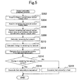
- the routine shown in the flowchart of FIG. 5 is executed by the ECU 20 in the third embodiment to judge whether the ethanol concentration sensor 16 is rational. Steps performed by the routine will be described below.
- step S302 the output value of the ethanol concentration sensor 16 is acquired in step S302, which is the first step.
- step S304 the output value of the remaining fuel amount sensor 22 is acquired.
- step S306 the output value of the remaining fuel amount sensor 22 is corrected in accordance with the output value of the ethanol concentration sensor 16.
- step S308 the amount of fuel remaining in the fuel tank 2 is calculated from the corrected output value of the remaining fuel amount sensor 22.
- the steps performed so far are the same as those in the first and second embodiments.
- the routine proceeds to step S310 and the change in the amount of remaining fuel during a predetermined period is calculated.
- the length of the predetermined period is not specifically limited. However, it is preferred that the predetermined period be long enough to encounter a definite change in the calculated remaining fuel amount.
- step S312 the amount of fuel consumed in the fuel tank 2 during the predetermined period is calculated from the amount of fuel injected from the injector 10 during the predetermined period.
- the amount of fuel injected from the injector 10 is determined by the pressure applied to the fuel and the time during which the injector 10 is driven, ethanol concentration does not influence the amount of fuel consumption calculated in step S312.
- the fuel consumption amount calculated in step S312 can be used as the information for verifying the accuracy of the change in the remaining fuel amount, which is calculated in step S310.
- step S314 it is judged whether the ethanol concentration sensor 16 is rational. More specifically, the change in the remaining fuel amount, which is calculated in step S310, is compared against the fuel consumption amount calculated in step S312. The judgment in step S314 can be formulated each time the predetermined period elapses.
- step S314 If the comparison result obtained in step S314 indicates that the difference between the calculated change in the remaining fuel amount and the calculated fuel consumption amount is not greater than a predetermined threshold value, the routine concludes that the calculated change in the remaining fuel amount is correct. If the calculated change in the remaining fuel amount is correct, it can be concluded that the output value of the ethanol concentration sensor 16, which is used for the calculation, is reliable. In this instance, the routine proceeds to step S316 and it is concluded that the rationality of the ethanol concentration sensor 16 is maintained.
- the routine proceeds to step S316 and it is concluded that the rationality of the ethanol concentration sensor 16 is lost.
- an ethanol concentration sensor 26 may be installed in the middle of the main flow path as indicated in FIG. 6 . Further, although the ethanol concentration sensor 26 is disposed outside the fuel tank 2 shown in FIG. 6 , the ethanol concentration sensor 26 may be disposed inside the fuel tank 2.
- the alcohol concentration sensor to be subjected to a rationality diagnosis is not limited to a capacitance-type alcohol concentration sensor.
- the alcohol concentration sensor generates an output value indicative of alcohol concentration
- the alcohol concentration sensor to be subjected to a rationality diagnosis may use any sensing method.
- a sensor that measures the alcohol concentration in accordance, for instance, with a refractive index, transmittance, specific gravity, or density may be employed.
Landscapes
- Engineering & Computer Science (AREA)
- Chemical & Material Sciences (AREA)
- Combustion & Propulsion (AREA)
- Mechanical Engineering (AREA)
- General Engineering & Computer Science (AREA)
- Oil, Petroleum & Natural Gas (AREA)
- Physics & Mathematics (AREA)
- Power Engineering (AREA)
- General Physics & Mathematics (AREA)
- Electromagnetism (AREA)
- Thermal Sciences (AREA)
- Fluid Mechanics (AREA)
- Health & Medical Sciences (AREA)
- Biomedical Technology (AREA)
- Combined Controls Of Internal Combustion Engines (AREA)
- Output Control And Ontrol Of Special Type Engine (AREA)
Abstract
Description
- The present invention relates to a rationality diagnostic device that diagnoses the rationality of an alcohol concentration sensor that measures the alcohol concentration of fuel used in an internal combustion engine.
- It is known that an FFV (flexible fuel vehicle) can use alcohol or alcohol-blended gasoline as fuel. An internal combustion engine for the FFV includes an alcohol concentration sensor that determines the alcohol concentration of an employed fuel. An output value of the alcohol concentration sensor is used as a parameter for air-fuel ratio control of the internal combustion engine. This not only acquires desired torque but also ensures satisfactory emissions performance without regard to the ethanol concentration of the employed fuel.
- As described above, the alcohol concentration sensor for the FFV internal combustion engine plays an important role to ensure the performance of the internal combustion engine. However, as is the case with the other sensors, there is no assurance that the alcohol concentration sensor properly functions at all times. Wire breakage, short-circuiting, sensor element deterioration, or other abnormality may occur in the alcohol concentration sensor. If, in the event of such abnormality, the output value of the alcohol concentration sensor is used to control the internal combustion engine, then an operation appropriate for the alcohol concentration of the employed fuel cannot be performed. This causes the deterioration of internal combustion engine performance such as emissions performance and fuel efficiency.
- As such being the case, it is demanded that the rationality of the alcohol concentration sensor for the FFV internal combustion engine be diagnosed to verify the reliability of the output value of the alcohol concentration sensor. However, it is difficult to directly verify the accuracy of the output value of the alcohol concentration sensor. The reason is that it is not easy to accurately measure the alcohol concentration by using means other than the alcohol concentration sensor. It is quite difficult to prepare a necessary standard at the time of verification.
- Under such circumstances, a technology disclosed in Japanese Patent No.
4477644 - However, air-fuel ratio changes are brought about by various multiple factors in addition to fuel injection amount changes. Hence, even when the actual air-fuel ratio is closed to the target air-fuel ratio, it cannot always be said that the rationality of the alcohol concentration sensor is maintained. The technology described in Japanese Patent No.
4477644 - An alternative method for diagnosing the rationality of the alcohol concentration sensor would be to prepare two alcohol concentration sensors that generate the same output when no abnormality exists, and compare the output values of the alcohol concentration sensors. If the alcohol concentration sensors generate different output values or the difference between their output values is greater than a threshold value when the alcohol concentration of the employed fuel is changed, this method makes it possible to conclude that the alcohol concentration sensors are no longer rational.
- In reality, however, the alcohol concentration of the fuel employed for the FFV internal combustion engine changes only when it is fueled. Therefore, even if an alcohol concentration sensor abnormality occurs in such a manner as to decrease the reliability of the sensor output value, such an abnormality cannot be detected until a refueling is performed later. Further, if the fuel added at the time of refueling has the same alcohol concentration as the fuel remaining in a fuel tank, the output values of the alcohol concentration sensors remain unchanged. Therefore, the alcohol concentration sensor abnormality still cannot be detected.
- As explained above, the conventionally proposed technology for diagnosing the rationality of the alcohol concentration sensor is not adequately capable of diagnosing the rationality of the alcohol concentration sensor properly and easily.
-
- Patent Document 1: Japanese Patent No.
4477644 - Patent Document 2:
JP-A-2010-071081 - Patent Document 3:
JP-A-1994-027063 - Patent Document 4:
JP-A-1993-010943 - Patent Document 5:
JP-A-1998-184479 - Patent Document 6:
JP-A-2006-114487 - Patent Document 7:
JP-A-2005-127724 - An object of the present invention is to properly and easily diagnose the rationality of an alcohol concentration sensor that measures the alcohol concentration of fuel used in an internal combustion engine. To achieve the above object, the present invention provides a below-described rationality diagnostic device for an alcohol concentration sensor.
- The rationality diagnostic device for an alcohol concentration sensor, which is provided by the present invention, includes a capacitance-type remaining fuel amount sensor as the remaining fuel amount sensor to be disposed in a fuel tank. The output characteristics of the capacitance-type remaining fuel amount sensor are such that its output value is determined in accordance with the amount of fuel remaining in the fuel tank and the alcohol concentration of the fuel. To eliminate an alcohol-concentration-dependent component from the output value of the remaining fuel amount sensor, the rationality diagnostic device corrects the output value of the remaining fuel amount sensor in accordance with the output value of the alcohol concentration sensor. If the rationality of the alcohol concentration sensor is maintained, the corrected output value of the remaining fuel amount sensor should properly represent the amount of fuel remaining in the fuel tank. The rationality diagnostic device verifies the accuracy of the corrected output value of the remaining fuel amount sensor to judge whether the rationality of the alcohol concentration sensor is maintained.
- Verifying the accuracy of the corrected output value of the remaining fuel amount sensor is extremely easier than verifying the accuracy of the output value of the alcohol concentration sensor. The reason is that it is not difficult to prepare a standard for verification as the corrected output value of the remaining fuel amount sensor is associated with a remaining fuel amount that can be measured by various well-known means. Therefore, the rationality diagnostic device can easily diagnose the rationality of the alcohol concentration sensor. In addition, the rationality diagnostic device can make a diagnosis when the output value of the remaining fuel amount sensor and the output value of the alcohol concentration sensor are available. Consequently, the rationality diagnostic device can quickly diagnose the rationality of the alcohol concentration sensor.
- If the remaining fuel amount sensor is abnormal, the accuracy of the output value of the remaining fuel amount sensor decreases even when the alcohol concentration sensor is normal. Therefore, the rationality of the alcohol concentration sensor could be judged to be lost no matter whether the alcohol concentration sensor is normal. However, an abnormality in the alcohol concentration sensor should be found without fail in order to ensure the emissions performance of the internal combustion engine. Hence, the aforementioned judgment does not constitute any problem. The reason is that a certain abnormality exists in a system and needs to be corrected by performing, for instance, an inspection procedure and a parts replacement procedure. The rationality diagnostic device makes it possible to surely prevent an erroneous judgment from being formulated to conclude that the rationality is maintained in a situation where the rationality of the alcohol concentration sensor is lost due to its abnormality or fault.
- Specifically, the following methods may be employed to verify the accuracy of the corrected output value of the remaining fuel amount sensor.
- A first method calculates the remaining fuel amount from the corrected output value of the remaining fuel amount sensor when the fuel tank is in a particular known state concerning the remaining fuel amount. The first method then compares the calculated remaining fuel amount against a known remaining fuel amount in the particular state, and verifies the accuracy of the output value of the remaining fuel amount sensor in accordance with the result of comparison. If the calculated remaining fuel amount agrees with the known remaining fuel amount or the difference between them is not greater than a threshold value, the first method makes it possible to conclude that the accuracy of the corrected output value of the remaining fuel amount sensor is acceptable. In such an instance, a diagnosis is made that the rationality of the alcohol concentration sensor is maintained.
- A second method not only calculates the remaining fuel amount from the corrected output value of a first remaining fuel amount sensor, but also measures the remaining fuel amount with a second remaining fuel amount sensor whose output value is not dependent on alcohol concentration. The second method then compares the calculated remaining fuel amount against the value measured by the second remaining fuel amount sensor, and verifies the accuracy of the corrected output value of the first remaining fuel sensor in accordance with the result of comparison. If the calculated remaining fuel amount agrees with the value measured by the second remaining fuel amount sensor or the difference between them is not greater than a threshold value, the second method makes it possible to conclude that the accuracy of the corrected output value of the first remaining fuel amount sensor is acceptable.
- A third method not only calculates the change in the remaining fuel amount during a predetermined period in accordance with the corrected output value of the remaining fuel amount sensor, but also calculates the amount of fuel consumption during the predetermined period in accordance with the amount of fuel injected from an injector. The third method then compares the calculated change in the remaining fuel amount against the calculated amount of fuel consumption, and verifies the accuracy of the corrected output value of the remaining fuel amount sensor in accordance with the result of comparison. If the calculated change in the remaining fuel amount agrees with the calculated amount of fuel consumption or the difference between them is not greater than a threshold value, the third method makes it possible to conclude that the accuracy of the corrected output value of the remaining fuel amount sensor is acceptable.
-
-
FIG. 1 is a schematic diagram illustrating the configuration of a fuel supply system for an internal combustion engine to which an ethanol concentration sensor rationality diagnostic device according to a first embodiment of the present invention is applied. -
FIG. 2 is a graph illustrating the output characteristics of a capacitance-type remaining fuel amount sensor. -
FIG. 3 is a flowchart illustrating an ethanol concentration sensor rationality judgment routine that is executed in the first embodiment of the present invention. -
FIG. 4 is a flowchart illustrating an ethanol concentration sensor rationality judgment routine that is executed in a second embodiment of the present invention. -
FIG. 5 is a flowchart illustrating an ethanol concentration sensor rationality judgment routine that is executed in a third embodiment of the present invention. -
FIG. 6 is a schematic diagram illustrating a modified example of a position at which an ethanol concentration sensor is disposed in the fuel supply system. - A first embodiment of the present invention will now be described with reference to the accompanying drawings.
- A rationality diagnostic device according to the first embodiment is applied to an alcohol concentration sensor (hereinafter referred to as the ethanol concentration sensor) for an FFV internal combustion engine that can use ethanol, gasoline, or ethanol-blended gasoline as fuel.
FIG. 1 is a schematic diagram illustrating the configuration of a fuel supply system for an internal combustion engine that includes the ethanol concentration sensor rationality diagnostic device according to the present embodiment. - The fuel supply system shown in
FIG. 1 includes theethanol concentration sensor 16, which is disposed in afuel tank 2. It should be noted, however, that theethanol concentration sensor 16 is not directly immersed in the fuel stored in thefuel tank 2, but is placed in afuel container 18 provided in thefuel tank 2. The top of thefuel container 18 is open. The bottom of thefuel container 18 is provided with afuel outlet 18a that discharges the fuel trapped inside thefuel container 18. Theethanol concentration sensor 16 according to the present embodiment is a capacitance-type sensor whoseelectrode section 16a is completely housed in thefuel container 18. - The
fuel container 18 is connected to the leading end of areturn flow path 12. Thereturn flow path 12 branches off from amain flow path 6 that connects afuel pump 4, which draws and pressurizes the fuel in thefuel tank 2, to adelivery pipe 8, which distributes the fuel to aninjector 10 of each cylinder. Apressure regulator 14 is installed in the middle of thereturn flow path 12. Thepressure regulator 14 is a valve that adjusts the pressure applied to the fuel in themain flow path 6. When thepressure regulator 14 opens, part of the pressurized fuel returns to thefuel tank 2 through thereturn flow path 12. In this instance, the fuel discharged from thereturn flow path 12 is introduced into thefuel container 18. Theelectrode section 16a of theethanol concentration sensor 16 is then immersed in the fuel so that theethanol concentration sensor 16 can measure the concentration of ethanol. To permit the fuel to be stored in thefuel container 18, the hole diameter of thefuel outlet 18a is designed so that the flow rate of the fuel discharged from thefuel outlet 18a does not exceed the flow rate of the fuel introduced from thereturn flow path 12. - A remaining
fuel amount sensor 22 is disposed in thefuel tank 2. The remainingfuel amount sensor 22 is a capacitance-type sensor whoseelectrode section 22a is extended from the ceiling of thefuel tank 2 to its bottom. The remainingfuel amount sensor 22, which is a capacitance-type sensor, has such output characteristics that its output value is determined by the amount of fuel remaining in thefuel tank 2 and the ethanol concentration of the fuel as shown inFIG. 2. FIG. 2 is a graph illustrating the relationship between a remaining fuel amount and a sensor output value. More specifically, line E0 indicates the relationship between the remaining fuel amount and sensor output value when the ethanol concentration of fuel is 0%, whereas line E85 indicates the relationship between the remaining fuel amount and sensor output value when the ethanol concentration of fuel is 85%. In this document, the term "remaining fuel amount" represents not the mass of fuel but the volume of fuel. - The output values of the
ethanol concentration sensor 16 and the remainingfuel amount sensor 22 are both loaded into anECU 20, which is a control device for the internal combustion engine. TheECU 20 determines the ethanol concentration of an employed fuel from the output value of theethanol concentration sensor 16. The determined ethanol concentration is used as a parameter that determines a fuel injection amount for air-fuel ratio control. The determined ethanol concentration is also used during a process that determines the remaining fuel amount from the output value of the remainingfuel amount sensor 22. As mentioned earlier, the output value of the remainingfuel amount sensor 22 is affected by both the remaining fuel amount and the ethanol concentration. Therefore, when measuring the remaining fuel amount by using the output value of the remainingfuel amount sensor 22, it is necessary to eliminate an ethanol-concentration-dependent component from the sensor output value. TheECU 20 corrects the output value of the remainingfuel amount sensor 22 in accordance with the output value of theethanol concentration sensor 16, and calculates the remaining fuel amount from the corrected output value of the remainingfuel amount sensor 22. - Further, the output values of various sensors other than the
ethanol concentration sensor 16 and the remainingfuel amount sensor 22 are also loaded into theECU 20. The present embodiment includes a liquidlevel detection switch 24 that is one of the various sensors, placed at a predetermined height in thefuel tank 2, and used to detect the liquid level of fuel stored in thefuel tank 2. The liquidlevel detection switch 24 outputs an ON signal when the liquid level of the fuel in thefuel tank 2 is higher than theswitch 24, and outputs an OFF signal when the liquid level is lower than theswitch 24. The output values of these various sensors inform theECU 20 of the operating status and operating conditions of the internal combustion engine. In accordance with such information, theECU 20 controls various actuators concerning the operation of the internal combustion engine. - The rationality diagnostic device according to the present embodiment is implemented when the
ECU 20 functions as an arithmetic processing unit for the rationality diagnostic device in the above-described fuel supply system configuration. When theECU 20 functions as the above-mentioned arithmetic processing unit, theECU 20 executes a rationality judgment routine shown in the flowchart ofFIG. 3 . The routine is executed at fixed intervals during the operation of the internal combustion engine. - According to the routine shown in
FIG. 3 , the output value of theethanol concentration sensor 16 is acquired in step S102, which is the first step. In step S104, the output value of the remainingfuel amount sensor 22 is acquired. In step S106, the output value of the remainingfuel amount sensor 22 is corrected in accordance with the output value of theethanol concentration sensor 16. For example, a correction coefficient is determined in accordance with the output value of theethanol concentration sensor 16, and the output value of the remainingfuel amount sensor 22 is multiplied by the correction coefficient. In step S108, the amount of fuel remaining in thefuel tank 2 is calculated from the corrected output value of the remainingfuel amount sensor 22. - In step S110, it is judged whether the signal of the liquid
level detection switch 24 has changed from ON to OFF or from OFF to ON. The signal changes from ON to OFF when the liquid level drops due to fuel consumption. The signal changes from OFF to ON when the liquid level rises due to fueling. When the signal of the liquidlevel detection switch 24 changes, the liquid level coincides with the height at which the liquidlevel detection switch 24 is installed. The remaining fuel amount at the height of the liquidlevel detection switch 24 is known and stored in theECU 20 as the known information for verification. - The routine does not formulate a rationality judgment until the signal of the liquid
level detection switch 24 changes. When the signal of the liquidlevel detection switch 24 changes, the routine proceeds to step S112 and it is judged whether theethanol concentration sensor 16 is rational. In the present embodiment, a rationality judgment is formulated by verifying the accuracy of the remaining fuel amount calculated in step S108. In step S112, therefore, the remaining fuel amount calculated in step S108 is compared against the remaining fuel amount that is stored in theECU 20 for verification purposes. - If the comparison result obtained in step S112 indicates that the difference between the calculated remaining fuel amount and the remaining fuel amount for verification is not greater than a predetermined threshold value, the routine concludes that the calculated remaining fuel amount is correct. If the calculated remaining fuel amount is correct, it can be concluded that the output value of the
ethanol concentration sensor 16, which is used for the calculation, is reliable. In this instance, the routine proceeds to step S114 and it is concluded that the rationality of theethanol concentration sensor 16 is maintained. - If, on the other hand, the difference between the calculated remaining fuel amount and the remaining fuel amount for verification is greater than the predetermined threshold value, the calculated remaining fuel amount is not correct. If the calculated remaining fuel amount is incorrect, it is due to an abnormality in either the
ethanol concentration sensor 16 or the remainingfuel amount sensor 22. However, it does not matter which of thesesensors ethanol concentration sensor 16 be detected without fail. In this case, therefore, no problem occurs even if theethanol concentration sensor 16 is suspected of abnormality. In either case, there is a certain abnormality in the system. Therefore, even if theethanol concentration sensor 16 is normal, it is necessary to perform an inspection procedure and a parts replacement procedure. Hence, if the comparison result obtained in step S112 indicates that the calculated remaining fuel amount is incorrect, the routine proceeds to step S116 and it is concluded that the rationality of theethanol concentration sensor 16 is lost. - When the routine formulates a rationality judgment as described above, it is possible to surely prevent an erroneous judgment from being formulated to conclude that the rationality is maintained in a situation where the rationality of the
ethanol concentration sensor 16 is lost due to its abnormality or fault. If a diagnosis is made that the rationality of theethanol concentration sensor 16 is lost, theECU 20 uses a malfunction indicator lamp (MIL) or other indicator to notify a driver of the occurrence of abnormality. - A second embodiment of the present invention will now be described with reference to the accompanying drawings.
- As is the case with the rationality diagnostic device according to the first embodiment, the rationality diagnostic device according to the second embodiment is applied to an ethanol concentration sensor for an internal combustion engine having the fuel supply system shown in
FIG. 1 . However, the element identified by thereference numeral 24 inFIG. 1 is a float-type remaining fuel amount sensor in the second embodiment although it is a liquid level detection switch in the first embodiment. - The second embodiment differs from the first embodiment in the method of judging whether the
ethanol concentration sensor 16 is rational. The routine shown in the flowchart ofFIG. 4 is executed by theECU 20 in the second embodiment to judge whether theethanol concentration sensor 16 is rational. Steps performed by the routine will be described below. - According to the routine shown in
FIG. 4 , the output value of theethanol concentration sensor 16 is acquired in step S202, which is the first step. In step S204, the output value of the remainingfuel amount sensor 22 is acquired. In step S206, the output value of the remainingfuel amount sensor 22 is corrected in accordance with the output value of theethanol concentration sensor 16. In step S208, the amount of fuel remaining in thefuel tank 2 is calculated from the corrected output value of the remainingfuel amount sensor 22. The steps performed so far are the same as those in the first embodiment. - Next, the routine proceeds to step S210, in which the output value of the float-type remaining fuel amount sensor is loaded into the
ECU 20. The output value of the float-type remaining fuel amount sensor remains unaffected by ethanol concentration unlike the output value of a capacitance-type sensor. TheECU 20 calculates the amount of fuel remaining in thefuel tank 2 from the output value of the float-type remaining fuel amount sensor. The remaining fuel amount measured in step S210 is used as the information for verifying the accuracy of the remaining fuel amount calculated in step S208. - In step S212, a judgment is formulated by comparing the remaining fuel amount calculated in step S208 against the remaining fuel amount measured by the float-type remaining fuel amount sensor. Unlike the judgment formulated in step S112 of the routine shown in
FIG. 3 , the judgment in step S212 can be formulated each time the routine is executed. In other words, the rationality judgment method employed in the second embodiment provides more judgment opportunities than the rationality judgment method employed in the first embodiment. - If the comparison result obtained in step S212 indicates that the difference between the calculated remaining fuel amount and the remaining fuel amount measured by the float-type remaining fuel amount sensor is not greater than a predetermined threshold value, it is concluded that the calculated remaining fuel amount is correct. If the calculated remaining fuel amount is correct, it can be concluded that the output value of the
ethanol concentration sensor 16 is reliable. In this instance, the routine proceeds to step S214 and it is concluded that the rationality of theethanol concentration sensor 16 is maintained. - If, on the other hand, the difference between the calculated remaining fuel amount and the remaining fuel amount measured by the float-type remaining fuel amount sensor is greater than the predetermined threshold value, the calculated remaining fuel amount is not correct. If the calculated remaining fuel amount is incorrect, it is conceivable that the output value of the
ethanol concentration sensor 16 may be unreliable. Hence, the routine proceeds to step S216 and it is concluded that the rationality of theethanol concentration sensor 16 is lost. - A third embodiment of the present invention will now be described with reference to the accompanying drawings.
- As is the case with the rationality diagnostic device according to the first embodiment, the rationality diagnostic device according to the third embodiment is applied to an ethanol concentration sensor for an internal combustion engine having the fuel supply system shown in
FIG. 1 . In the third embodiment, the sensor identified by thereference numeral 24 inFIG. 1 may be of any type. - The third embodiment is characterized by its method of judging whether the
ethanol concentration sensor 16 is rational. The routine shown in the flowchart ofFIG. 5 is executed by theECU 20 in the third embodiment to judge whether theethanol concentration sensor 16 is rational. Steps performed by the routine will be described below. - According to the routine shown in
FIG. 5 , the output value of theethanol concentration sensor 16 is acquired in step S302, which is the first step. In step S304, the output value of the remainingfuel amount sensor 22 is acquired. In step S306, the output value of the remainingfuel amount sensor 22 is corrected in accordance with the output value of theethanol concentration sensor 16. In step S308, the amount of fuel remaining in thefuel tank 2 is calculated from the corrected output value of the remainingfuel amount sensor 22. The steps performed so far are the same as those in the first and second embodiments. - Next, the routine proceeds to step S310 and the change in the amount of remaining fuel during a predetermined period is calculated. The length of the predetermined period is not specifically limited. However, it is preferred that the predetermined period be long enough to encounter a definite change in the calculated remaining fuel amount.
- Next, in step S312, the amount of fuel consumed in the
fuel tank 2 during the predetermined period is calculated from the amount of fuel injected from theinjector 10 during the predetermined period. As the amount of fuel injected from theinjector 10 is determined by the pressure applied to the fuel and the time during which theinjector 10 is driven, ethanol concentration does not influence the amount of fuel consumption calculated in step S312. Hence, the fuel consumption amount calculated in step S312 can be used as the information for verifying the accuracy of the change in the remaining fuel amount, which is calculated in step S310. - In step S314, it is judged whether the
ethanol concentration sensor 16 is rational. More specifically, the change in the remaining fuel amount, which is calculated in step S310, is compared against the fuel consumption amount calculated in step S312. The judgment in step S314 can be formulated each time the predetermined period elapses. - If the comparison result obtained in step S314 indicates that the difference between the calculated change in the remaining fuel amount and the calculated fuel consumption amount is not greater than a predetermined threshold value, the routine concludes that the calculated change in the remaining fuel amount is correct. If the calculated change in the remaining fuel amount is correct, it can be concluded that the output value of the
ethanol concentration sensor 16, which is used for the calculation, is reliable. In this instance, the routine proceeds to step S316 and it is concluded that the rationality of theethanol concentration sensor 16 is maintained. - If, on the other hand, the difference between the calculated change in the remaining fuel amount and the calculated fuel consumption amount is greater than the predetermined threshold value, the calculated change in the remaining fuel amount is not correct. In such an instance, it is conceivable that the output value of the
ethanol concentration sensor 16 may be unreliable. Hence, the routine proceeds to step S316 and it is concluded that the rationality of theethanol concentration sensor 16 is lost. - While the present invention has been described in connection with the foregoing embodiments, it should be understood that the present invention is not limited to the foregoing embodiments. The present invention extends to various modifications that nevertheless fall within the scope and spirit of the present invention. For example, an
ethanol concentration sensor 26 may be installed in the middle of the main flow path as indicated inFIG. 6 . Further, although theethanol concentration sensor 26 is disposed outside thefuel tank 2 shown inFIG. 6 , theethanol concentration sensor 26 may be disposed inside thefuel tank 2. - When the present invention is to be implemented, the alcohol concentration sensor to be subjected to a rationality diagnosis is not limited to a capacitance-type alcohol concentration sensor. As far as the alcohol concentration sensor generates an output value indicative of alcohol concentration, the alcohol concentration sensor to be subjected to a rationality diagnosis may use any sensing method. For example, a sensor that measures the alcohol concentration in accordance, for instance, with a refractive index, transmittance, specific gravity, or density may be employed.
-
- 2
- Fuel tank
- 4
- Fuel pump
- 6
- Main flow path
- 8
- Delivery pipe
- 10
- Injector
- 12
- Return flow path
- 14
- Pressure regulator
- 16
- Ethanol concentration sensor
- 18
- Fuel container
- 20
- ECU
- 22
- Remaining fuel amount sensor
Claims (4)
- A rationality diagnostic device for diagnosing the rationality of an alcohol concentration sensor that measures the alcohol concentration of fuel used in an internal combustion engine, the rationality diagnostic device comprising:a capacitance-type remaining fuel amount sensor whose output value is determined in accordance with the amount of fuel remaining in a fuel tank and the alcohol concentration of the fuel;sensor output correction means for correcting the output value of the remaining fuel amount sensor in accordance with the output value of the alcohol concentration sensor; andrationality judgment means for verifying the accuracy of the corrected output value of the remaining fuel amount sensor to judge whether the rationality of the alcohol concentration sensor is maintained.
- The rationality diagnostic device according to claim 1, wherein, when the fuel tank is in a particular known state concerning the amount of remaining fuel, the rationality judgment means verifies the accuracy of the corrected output value of the remaining fuel amount sensor by comparing the remaining fuel amount calculated in accordance with the corrected output value of the remaining fuel amount sensor against the known remaining fuel amount in the particular state.
- The rationality diagnostic device according to claim 1, wherein the rationality judgment means verifies the accuracy of the corrected output value of the remaining fuel amount sensor by comparing the remaining fuel amount calculated in accordance with the corrected output value of the remaining fuel amount sensor against a remaining fuel amount measured by another remaining fuel amount sensor whose output value is not dependent on alcohol concentration.
- The rationality diagnostic device according to claim 1, wherein the rationality judgment means verifies the accuracy of the corrected output value of the remaining fuel amount sensor by comparing the change in the remaining fuel amount during a predetermined period, which is calculated in accordance with the corrected output value of the remaining fuel amount sensor, against the amount of fuel consumption during the predetermined period, which is calculated from the amount of fuel injected from an injector.
Applications Claiming Priority (1)
| Application Number | Priority Date | Filing Date | Title |
|---|---|---|---|
| PCT/JP2010/073762 WO2012090317A1 (en) | 2010-12-28 | 2010-12-28 | Rationality diagnostic device for alcohol concentration sensors |
Publications (3)
| Publication Number | Publication Date |
|---|---|
| EP2647820A1 true EP2647820A1 (en) | 2013-10-09 |
| EP2647820A4 EP2647820A4 (en) | 2014-07-16 |
| EP2647820B1 EP2647820B1 (en) | 2015-12-02 |
Family
ID=46382466
Family Applications (1)
| Application Number | Title | Priority Date | Filing Date |
|---|---|---|---|
| EP10857098.7A Not-in-force EP2647820B1 (en) | 2010-12-28 | 2010-12-28 | Rationality diagnostic device for alcohol concentration sensors |
Country Status (5)
| Country | Link |
|---|---|
| US (1) | US8656773B2 (en) |
| EP (1) | EP2647820B1 (en) |
| JP (1) | JP5240415B2 (en) |
| CN (1) | CN103270281B (en) |
| WO (1) | WO2012090317A1 (en) |
Families Citing this family (2)
| Publication number | Priority date | Publication date | Assignee | Title |
|---|---|---|---|---|
| JP5984705B2 (en) | 2012-03-29 | 2016-09-06 | 愛三工業株式会社 | Fuel characteristic measuring device |
| DE102023205973A1 (en) | 2023-06-26 | 2024-06-06 | Vitesco Technologies GmbH | Method and arrangement for determining the quality and fill level of a liquid |
Family Cites Families (26)
| Publication number | Priority date | Publication date | Assignee | Title |
|---|---|---|---|---|
| JPS57168169A (en) * | 1981-04-10 | 1982-10-16 | Nissan Motor Co Ltd | Electrostatic capacitance detector |
| JPS5835421A (en) * | 1981-08-27 | 1983-03-02 | Nissan Motor Co Ltd | Fuel sensor |
| JPH0359423A (en) * | 1989-07-27 | 1991-03-14 | Fuji Heavy Ind Ltd | Fuel display system |
| JPH03285119A (en) * | 1990-03-31 | 1991-12-16 | Mazda Motor Corp | Alarming apparatus of remaining fuel in fuel tank |
| JPH04279741A (en) * | 1991-03-08 | 1992-10-05 | Fuji Heavy Ind Ltd | Control method of engine for ffv |
| US5255656A (en) * | 1991-06-27 | 1993-10-26 | Borg-Warner Automotive, Inc. | Alcohol concentration sensor for automotive fuels |
| JPH0510943A (en) * | 1991-07-02 | 1993-01-19 | Japan Electron Control Syst Co Ltd | Alarming device on residual quantity of fuel of vehicle |
| JPH0627063A (en) | 1992-07-07 | 1994-02-04 | Mazda Motor Corp | Residual fuel detector |
| US6892572B2 (en) * | 1994-05-09 | 2005-05-17 | Automotive Technologies International, Inc. | Method and apparatus for measuring the quantity of a liquid in a vehicle container |
| JPH10184479A (en) * | 1996-12-27 | 1998-07-14 | Hitachi Ltd | Failure diagnosis device for fuel level detection means |
| JP3903943B2 (en) * | 2003-04-07 | 2007-04-11 | 日産自動車株式会社 | Fuel property estimation device for internal combustion engine |
| JP4104527B2 (en) | 2003-10-21 | 2008-06-18 | 株式会社テルモ工業 | Level sensor |
| JP2006114487A (en) | 2004-09-16 | 2006-04-27 | Matsushita Electric Ind Co Ltd | Direct methanol fuel cell, fuel liquid level detection method, and methanol concentration detection method |
| US8200412B2 (en) * | 2006-04-04 | 2012-06-12 | Toyota Jidosha Kabushiki Kaisha | Controller for internal combustion engine |
| JP2008144723A (en) * | 2006-12-13 | 2008-06-26 | Toyota Motor Corp | Control device for internal combustion engine |
| JP4477644B2 (en) | 2007-01-23 | 2010-06-09 | トヨタ自動車株式会社 | Control device for internal combustion engine |
| JP4341709B2 (en) * | 2007-08-13 | 2009-10-07 | トヨタ自動車株式会社 | Control device for internal combustion engine |
| US20090090179A1 (en) * | 2007-10-05 | 2009-04-09 | Jesus Carmona | Sensor with polymer substrate for use in corrosive liquids |
| JP4883321B2 (en) * | 2008-02-25 | 2012-02-22 | 三菱自動車工業株式会社 | Control device for internal combustion engine |
| DE102008020928B4 (en) * | 2008-04-25 | 2014-04-17 | Continental Automotive Gmbh | A method for controlling an air-fuel ratio and method for detecting a fuel quality |
| JP4561906B2 (en) * | 2008-08-21 | 2010-10-13 | トヨタ自動車株式会社 | Fuel supply device for flexible fuel internal combustion engine |
| JP2010071081A (en) * | 2008-09-16 | 2010-04-02 | Denso Corp | Device for diagnosing abnormality of fuel level detector |
| JP2010190075A (en) * | 2009-02-17 | 2010-09-02 | Denso Corp | Malfunction diagnosing apparatus for internal combustion engine |
| JP5195604B2 (en) * | 2009-04-16 | 2013-05-08 | 株式会社デンソー | Liquid concentration detector |
| JP2010275910A (en) * | 2009-05-27 | 2010-12-09 | Denso Corp | Control device for internal combustion engine |
| JP2011099349A (en) * | 2009-11-04 | 2011-05-19 | Denso Corp | Abnormality diagnosing device for alcohol sensor |
-
2010
- 2010-12-28 WO PCT/JP2010/073762 patent/WO2012090317A1/en not_active Ceased
- 2010-12-28 JP JP2012527938A patent/JP5240415B2/en not_active Expired - Fee Related
- 2010-12-28 US US13/516,888 patent/US8656773B2/en not_active Expired - Fee Related
- 2010-12-28 CN CN201080070985.5A patent/CN103270281B/en not_active Expired - Fee Related
- 2010-12-28 EP EP10857098.7A patent/EP2647820B1/en not_active Not-in-force
Also Published As
| Publication number | Publication date |
|---|---|
| US8656773B2 (en) | 2014-02-25 |
| CN103270281A (en) | 2013-08-28 |
| JPWO2012090317A1 (en) | 2014-06-05 |
| JP5240415B2 (en) | 2013-07-17 |
| CN103270281B (en) | 2014-10-08 |
| WO2012090317A1 (en) | 2012-07-05 |
| EP2647820B1 (en) | 2015-12-02 |
| US20130340496A1 (en) | 2013-12-26 |
| EP2647820A4 (en) | 2014-07-16 |
Similar Documents
| Publication | Publication Date | Title |
|---|---|---|
| EP2660448B1 (en) | Error detection device for internal combustion engine | |
| US8733167B2 (en) | Method and device for detecting a tank level | |
| JP4831015B2 (en) | Abnormality diagnosis device for internal combustion engine | |
| JP2010521625A (en) | Diagnosis method of shut-off valve | |
| SE532523C2 (en) | Method and system for diagnosing gas leakage in a gas-powered vehicle | |
| EP2177741A1 (en) | Method for diagnosing a gaseous fuel feeding system for an internal combustion engine | |
| US7966864B2 (en) | Method for ascertaining an ethanol content of a fuel | |
| CN102918244B (en) | Abnormality detection device for internal combustion engines | |
| US20110215813A1 (en) | Fuel property sensor abnormality determining device | |
| EP2647820B1 (en) | Rationality diagnostic device for alcohol concentration sensors | |
| CN102695865B (en) | Device for controlling bi-fuel engine | |
| US8862316B2 (en) | Method and device for diagnosing the operational state of a fuel supply system of an automobile internal combustion engine | |
| US10378473B2 (en) | Vehicle control device | |
| JP2010071081A (en) | Device for diagnosing abnormality of fuel level detector | |
| JP2012140879A (en) | Rationality diagnosis apparatus of fuel remaining amount sensor | |
| JP5482719B2 (en) | Failure detection device for internal combustion engine | |
| CN101655040B (en) | Diagnostic systems and methods for the high pressure side of fuel systems in common fuel piping engines | |
| JP2010084675A (en) | Abnormality detection device for internal combustion engine | |
| JP2016176400A (en) | Pressure sensor failure diagnosis method and common rail-type fuel injection control device | |
| KR100569078B1 (en) | Intake temperature sensor failure determination device and method | |
| CN110779984A (en) | Method for checking the plausibility of a sensor signal of a concentration sensor arranged in an SCR catalyst system | |
| JP2011094580A (en) | Responsiveness deterioration diagnosis device for alcohol concentration sensor |
Legal Events
| Date | Code | Title | Description |
|---|---|---|---|
| PUAI | Public reference made under article 153(3) epc to a published international application that has entered the european phase |
Free format text: ORIGINAL CODE: 0009012 |
|
| 17P | Request for examination filed |
Effective date: 20120322 |
|
| AK | Designated contracting states |
Kind code of ref document: A1 Designated state(s): AL AT BE BG CH CY CZ DE DK EE ES FI FR GB GR HR HU IE IS IT LI LT LU LV MC MK MT NL NO PL PT RO RS SE SI SK SM TR |
|
| DAX | Request for extension of the european patent (deleted) | ||
| A4 | Supplementary search report drawn up and despatched |
Effective date: 20140613 |
|
| RIC1 | Information provided on ipc code assigned before grant |
Ipc: F02D 45/00 20060101AFI20140606BHEP Ipc: F02D 41/22 20060101ALI20140606BHEP Ipc: F02D 19/06 20060101ALI20140606BHEP Ipc: G01F 23/26 20060101ALI20140606BHEP Ipc: F02D 19/08 20060101ALI20140606BHEP |
|
| GRAP | Despatch of communication of intention to grant a patent |
Free format text: ORIGINAL CODE: EPIDOSNIGR1 |
|
| GRAJ | Information related to disapproval of communication of intention to grant by the applicant or resumption of examination proceedings by the epo deleted |
Free format text: ORIGINAL CODE: EPIDOSDIGR1 |
|
| GRAP | Despatch of communication of intention to grant a patent |
Free format text: ORIGINAL CODE: EPIDOSNIGR1 |
|
| INTG | Intention to grant announced |
Effective date: 20150702 |
|
| INTG | Intention to grant announced |
Effective date: 20150710 |
|
| GRAS | Grant fee paid |
Free format text: ORIGINAL CODE: EPIDOSNIGR3 |
|
| GRAA | (expected) grant |
Free format text: ORIGINAL CODE: 0009210 |
|
| AK | Designated contracting states |
Kind code of ref document: B1 Designated state(s): AL AT BE BG CH CY CZ DE DK EE ES FI FR GB GR HR HU IE IS IT LI LT LU LV MC MK MT NL NO PL PT RO RS SE SI SK SM TR |
|
| REG | Reference to a national code |
Ref country code: GB Ref legal event code: FG4D |
|
| REG | Reference to a national code |
Ref country code: AT Ref legal event code: REF Ref document number: 763743 Country of ref document: AT Kind code of ref document: T Effective date: 20151215 Ref country code: CH Ref legal event code: EP |
|
| REG | Reference to a national code |
Ref country code: FR Ref legal event code: PLFP Year of fee payment: 6 |
|
| REG | Reference to a national code |
Ref country code: IE Ref legal event code: FG4D |
|
| REG | Reference to a national code |
Ref country code: DE Ref legal event code: R096 Ref document number: 602010029430 Country of ref document: DE |
|
| REG | Reference to a national code |
Ref country code: NL Ref legal event code: MP Effective date: 20160302 |
|
| REG | Reference to a national code |
Ref country code: LT Ref legal event code: MG4D |
|
| REG | Reference to a national code |
Ref country code: AT Ref legal event code: MK05 Ref document number: 763743 Country of ref document: AT Kind code of ref document: T Effective date: 20151202 |
|
| PG25 | Lapsed in a contracting state [announced via postgrant information from national office to epo] |
Ref country code: ES Free format text: LAPSE BECAUSE OF FAILURE TO SUBMIT A TRANSLATION OF THE DESCRIPTION OR TO PAY THE FEE WITHIN THE PRESCRIBED TIME-LIMIT Effective date: 20151202 Ref country code: NO Free format text: LAPSE BECAUSE OF FAILURE TO SUBMIT A TRANSLATION OF THE DESCRIPTION OR TO PAY THE FEE WITHIN THE PRESCRIBED TIME-LIMIT Effective date: 20160302 Ref country code: LT Free format text: LAPSE BECAUSE OF FAILURE TO SUBMIT A TRANSLATION OF THE DESCRIPTION OR TO PAY THE FEE WITHIN THE PRESCRIBED TIME-LIMIT Effective date: 20151202 |
|
| PG25 | Lapsed in a contracting state [announced via postgrant information from national office to epo] |
Ref country code: LV Free format text: LAPSE BECAUSE OF FAILURE TO SUBMIT A TRANSLATION OF THE DESCRIPTION OR TO PAY THE FEE WITHIN THE PRESCRIBED TIME-LIMIT Effective date: 20151202 Ref country code: SE Free format text: LAPSE BECAUSE OF FAILURE TO SUBMIT A TRANSLATION OF THE DESCRIPTION OR TO PAY THE FEE WITHIN THE PRESCRIBED TIME-LIMIT Effective date: 20151202 Ref country code: FI Free format text: LAPSE BECAUSE OF FAILURE TO SUBMIT A TRANSLATION OF THE DESCRIPTION OR TO PAY THE FEE WITHIN THE PRESCRIBED TIME-LIMIT Effective date: 20151202 Ref country code: RS Free format text: LAPSE BECAUSE OF FAILURE TO SUBMIT A TRANSLATION OF THE DESCRIPTION OR TO PAY THE FEE WITHIN THE PRESCRIBED TIME-LIMIT Effective date: 20151202 Ref country code: BE Free format text: LAPSE BECAUSE OF NON-PAYMENT OF DUE FEES Effective date: 20151231 Ref country code: NL Free format text: LAPSE BECAUSE OF FAILURE TO SUBMIT A TRANSLATION OF THE DESCRIPTION OR TO PAY THE FEE WITHIN THE PRESCRIBED TIME-LIMIT Effective date: 20151202 Ref country code: GR Free format text: LAPSE BECAUSE OF FAILURE TO SUBMIT A TRANSLATION OF THE DESCRIPTION OR TO PAY THE FEE WITHIN THE PRESCRIBED TIME-LIMIT Effective date: 20160303 Ref country code: PL Free format text: LAPSE BECAUSE OF FAILURE TO SUBMIT A TRANSLATION OF THE DESCRIPTION OR TO PAY THE FEE WITHIN THE PRESCRIBED TIME-LIMIT Effective date: 20151202 Ref country code: AT Free format text: LAPSE BECAUSE OF FAILURE TO SUBMIT A TRANSLATION OF THE DESCRIPTION OR TO PAY THE FEE WITHIN THE PRESCRIBED TIME-LIMIT Effective date: 20151202 |
|
| PG25 | Lapsed in a contracting state [announced via postgrant information from national office to epo] |
Ref country code: IS Free format text: LAPSE BECAUSE OF FAILURE TO SUBMIT A TRANSLATION OF THE DESCRIPTION OR TO PAY THE FEE WITHIN THE PRESCRIBED TIME-LIMIT Effective date: 20151202 |
|
| PG25 | Lapsed in a contracting state [announced via postgrant information from national office to epo] |
Ref country code: CZ Free format text: LAPSE BECAUSE OF FAILURE TO SUBMIT A TRANSLATION OF THE DESCRIPTION OR TO PAY THE FEE WITHIN THE PRESCRIBED TIME-LIMIT Effective date: 20151202 Ref country code: IT Free format text: LAPSE BECAUSE OF FAILURE TO SUBMIT A TRANSLATION OF THE DESCRIPTION OR TO PAY THE FEE WITHIN THE PRESCRIBED TIME-LIMIT Effective date: 20151202 |
|
| REG | Reference to a national code |
Ref country code: CH Ref legal event code: PL |
|
| PG25 | Lapsed in a contracting state [announced via postgrant information from national office to epo] |
Ref country code: EE Free format text: LAPSE BECAUSE OF FAILURE TO SUBMIT A TRANSLATION OF THE DESCRIPTION OR TO PAY THE FEE WITHIN THE PRESCRIBED TIME-LIMIT Effective date: 20151202 Ref country code: SK Free format text: LAPSE BECAUSE OF FAILURE TO SUBMIT A TRANSLATION OF THE DESCRIPTION OR TO PAY THE FEE WITHIN THE PRESCRIBED TIME-LIMIT Effective date: 20151202 Ref country code: RO Free format text: LAPSE BECAUSE OF FAILURE TO SUBMIT A TRANSLATION OF THE DESCRIPTION OR TO PAY THE FEE WITHIN THE PRESCRIBED TIME-LIMIT Effective date: 20151202 Ref country code: SM Free format text: LAPSE BECAUSE OF FAILURE TO SUBMIT A TRANSLATION OF THE DESCRIPTION OR TO PAY THE FEE WITHIN THE PRESCRIBED TIME-LIMIT Effective date: 20151202 Ref country code: PT Free format text: LAPSE BECAUSE OF FAILURE TO SUBMIT A TRANSLATION OF THE DESCRIPTION OR TO PAY THE FEE WITHIN THE PRESCRIBED TIME-LIMIT Effective date: 20160404 Ref country code: IS Free format text: LAPSE BECAUSE OF FAILURE TO SUBMIT A TRANSLATION OF THE DESCRIPTION OR TO PAY THE FEE WITHIN THE PRESCRIBED TIME-LIMIT Effective date: 20160402 |
|
| REG | Reference to a national code |
Ref country code: DE Ref legal event code: R097 Ref document number: 602010029430 Country of ref document: DE |
|
| REG | Reference to a national code |
Ref country code: IE Ref legal event code: MM4A |
|
| REG | Reference to a national code |
Ref country code: DE Ref legal event code: R084 Ref document number: 602010029430 Country of ref document: DE |
|
| PG25 | Lapsed in a contracting state [announced via postgrant information from national office to epo] |
Ref country code: MC Free format text: LAPSE BECAUSE OF FAILURE TO SUBMIT A TRANSLATION OF THE DESCRIPTION OR TO PAY THE FEE WITHIN THE PRESCRIBED TIME-LIMIT Effective date: 20151202 |
|
| PLBE | No opposition filed within time limit |
Free format text: ORIGINAL CODE: 0009261 |
|
| STAA | Information on the status of an ep patent application or granted ep patent |
Free format text: STATUS: NO OPPOSITION FILED WITHIN TIME LIMIT |
|
| PG25 | Lapsed in a contracting state [announced via postgrant information from national office to epo] |
Ref country code: IE Free format text: LAPSE BECAUSE OF NON-PAYMENT OF DUE FEES Effective date: 20151228 Ref country code: CH Free format text: LAPSE BECAUSE OF NON-PAYMENT OF DUE FEES Effective date: 20151231 Ref country code: DK Free format text: LAPSE BECAUSE OF FAILURE TO SUBMIT A TRANSLATION OF THE DESCRIPTION OR TO PAY THE FEE WITHIN THE PRESCRIBED TIME-LIMIT Effective date: 20151202 Ref country code: LI Free format text: LAPSE BECAUSE OF NON-PAYMENT OF DUE FEES Effective date: 20151231 |
|
| 26N | No opposition filed |
Effective date: 20160905 |
|
| REG | Reference to a national code |
Ref country code: FR Ref legal event code: PLFP Year of fee payment: 7 |
|
| GBPC | Gb: european patent ceased through non-payment of renewal fee |
Effective date: 20160302 |
|
| PG25 | Lapsed in a contracting state [announced via postgrant information from national office to epo] |
Ref country code: SI Free format text: LAPSE BECAUSE OF FAILURE TO SUBMIT A TRANSLATION OF THE DESCRIPTION OR TO PAY THE FEE WITHIN THE PRESCRIBED TIME-LIMIT Effective date: 20151202 |
|
| PG25 | Lapsed in a contracting state [announced via postgrant information from national office to epo] |
Ref country code: BE Free format text: LAPSE BECAUSE OF FAILURE TO SUBMIT A TRANSLATION OF THE DESCRIPTION OR TO PAY THE FEE WITHIN THE PRESCRIBED TIME-LIMIT Effective date: 20151202 |
|
| PG25 | Lapsed in a contracting state [announced via postgrant information from national office to epo] |
Ref country code: GB Free format text: LAPSE BECAUSE OF NON-PAYMENT OF DUE FEES Effective date: 20160302 |
|
| PG25 | Lapsed in a contracting state [announced via postgrant information from national office to epo] |
Ref country code: HU Free format text: LAPSE BECAUSE OF FAILURE TO SUBMIT A TRANSLATION OF THE DESCRIPTION OR TO PAY THE FEE WITHIN THE PRESCRIBED TIME-LIMIT; INVALID AB INITIO Effective date: 20101228 Ref country code: BG Free format text: LAPSE BECAUSE OF FAILURE TO SUBMIT A TRANSLATION OF THE DESCRIPTION OR TO PAY THE FEE WITHIN THE PRESCRIBED TIME-LIMIT Effective date: 20151202 |
|
| PG25 | Lapsed in a contracting state [announced via postgrant information from national office to epo] |
Ref country code: CY Free format text: LAPSE BECAUSE OF FAILURE TO SUBMIT A TRANSLATION OF THE DESCRIPTION OR TO PAY THE FEE WITHIN THE PRESCRIBED TIME-LIMIT Effective date: 20151202 |
|
| PG25 | Lapsed in a contracting state [announced via postgrant information from national office to epo] |
Ref country code: HR Free format text: LAPSE BECAUSE OF FAILURE TO SUBMIT A TRANSLATION OF THE DESCRIPTION OR TO PAY THE FEE WITHIN THE PRESCRIBED TIME-LIMIT Effective date: 20151202 |
|
| PG25 | Lapsed in a contracting state [announced via postgrant information from national office to epo] |
Ref country code: MT Free format text: LAPSE BECAUSE OF FAILURE TO SUBMIT A TRANSLATION OF THE DESCRIPTION OR TO PAY THE FEE WITHIN THE PRESCRIBED TIME-LIMIT Effective date: 20151202 |
|
| REG | Reference to a national code |
Ref country code: FR Ref legal event code: PLFP Year of fee payment: 8 |
|
| PG25 | Lapsed in a contracting state [announced via postgrant information from national office to epo] |
Ref country code: LU Free format text: LAPSE BECAUSE OF NON-PAYMENT OF DUE FEES Effective date: 20151228 |
|
| PG25 | Lapsed in a contracting state [announced via postgrant information from national office to epo] |
Ref country code: MK Free format text: LAPSE BECAUSE OF FAILURE TO SUBMIT A TRANSLATION OF THE DESCRIPTION OR TO PAY THE FEE WITHIN THE PRESCRIBED TIME-LIMIT Effective date: 20151202 Ref country code: TR Free format text: LAPSE BECAUSE OF FAILURE TO SUBMIT A TRANSLATION OF THE DESCRIPTION OR TO PAY THE FEE WITHIN THE PRESCRIBED TIME-LIMIT Effective date: 20151202 |
|
| PG25 | Lapsed in a contracting state [announced via postgrant information from national office to epo] |
Ref country code: AL Free format text: LAPSE BECAUSE OF FAILURE TO SUBMIT A TRANSLATION OF THE DESCRIPTION OR TO PAY THE FEE WITHIN THE PRESCRIBED TIME-LIMIT Effective date: 20151202 |
|
| PGFP | Annual fee paid to national office [announced via postgrant information from national office to epo] |
Ref country code: FR Payment date: 20211115 Year of fee payment: 12 Ref country code: DE Payment date: 20211102 Year of fee payment: 12 |
|
| REG | Reference to a national code |
Ref country code: DE Ref legal event code: R119 Ref document number: 602010029430 Country of ref document: DE |
|
| PG25 | Lapsed in a contracting state [announced via postgrant information from national office to epo] |
Ref country code: DE Free format text: LAPSE BECAUSE OF NON-PAYMENT OF DUE FEES Effective date: 20230701 |
|
| PG25 | Lapsed in a contracting state [announced via postgrant information from national office to epo] |
Ref country code: FR Free format text: LAPSE BECAUSE OF NON-PAYMENT OF DUE FEES Effective date: 20221231 |