EP2647809B1 - Wärmetauschersystem und verfahren zu dessen betrieb - Google Patents
Wärmetauschersystem und verfahren zu dessen betrieb Download PDFInfo
- Publication number
- EP2647809B1 EP2647809B1 EP13162219.3A EP13162219A EP2647809B1 EP 2647809 B1 EP2647809 B1 EP 2647809B1 EP 13162219 A EP13162219 A EP 13162219A EP 2647809 B1 EP2647809 B1 EP 2647809B1
- Authority
- EP
- European Patent Office
- Prior art keywords
- fuel
- heat exchanger
- attaching
- conditioner
- deoxygenator
- Prior art date
- Legal status (The legal status is an assumption and is not a legal conclusion. Google has not performed a legal analysis and makes no representation as to the accuracy of the status listed.)
- Active
Links
Images

Classifications
-
- F—MECHANICAL ENGINEERING; LIGHTING; HEATING; WEAPONS; BLASTING
- F02—COMBUSTION ENGINES; HOT-GAS OR COMBUSTION-PRODUCT ENGINE PLANTS
- F02C—GAS-TURBINE PLANTS; AIR INTAKES FOR JET-PROPULSION PLANTS; CONTROLLING FUEL SUPPLY IN AIR-BREATHING JET-PROPULSION PLANTS
- F02C3/00—Gas-turbine plants characterised by the use of combustion products as the working fluid
- F02C3/20—Gas-turbine plants characterised by the use of combustion products as the working fluid using a special fuel, oxidant, or dilution fluid to generate the combustion products
-
- F—MECHANICAL ENGINEERING; LIGHTING; HEATING; WEAPONS; BLASTING
- F02—COMBUSTION ENGINES; HOT-GAS OR COMBUSTION-PRODUCT ENGINE PLANTS
- F02C—GAS-TURBINE PLANTS; AIR INTAKES FOR JET-PROPULSION PLANTS; CONTROLLING FUEL SUPPLY IN AIR-BREATHING JET-PROPULSION PLANTS
- F02C7/00—Features, components parts, details or accessories, not provided for in, or of interest apart form groups F02C1/00 - F02C6/00; Air intakes for jet-propulsion plants
- F02C7/22—Fuel supply systems
Definitions
- the present invention relates to stabilizing fuel by deoxygenation, and more particularly to a heat exchanger fuel stabilization unit.
- Fuel is often utilized in aircraft as a coolant for various aircraft systems.
- the presence of dissolved oxygen in hydrocarbon jet fuels may be objectionable because the oxygen supports oxidation reactions that yield undesirable by-products. Dissolution of air in jet fuel results in an approximately 70 ppm oxygen concentration.
- aerated fuel is heated between 350 degrees F (or 177 degrees C) and 850 degrees F (or 454 degrees C)
- the oxygen initiates free radical reactions of the fuel resulting in deposits commonly referred to as "coke”or “coking”.
- Coke may be detrimental to the fuel lines and may inhibit combustion. The formation of such deposits may impair the normal functioning of a fuel system, either with respect to an intended heat exchange function or the efficient injection of fuel.
- FSU Fuel Stabilization Unit
- the FSU includes a plurality of fuel plates sandwiched between permeable membranes and porous substrate plates disposed within a housing. Each fuel plate defines a portion of the fuel passage and the porous plate backed permeable membranes define the remaining portions of the fuel passages.
- the permeable membrane includes Teflon® (PTFE) or other type of amorphous glassy polymer coating in contact with fuel within the fuel passages for preventing the bulk of liquid fuel from migrating through the permeable membrane and the porous plate.
- PTFE Teflon®
- the use of a plurality of similarly configured flat plates increases manufacturing efficiency and reduces overall cost. Further, the size and weight of the FSU is substantially reduced while increasing the capacity for removing dissolved oxygen from fuel. Moreover, the planar design is easily scalable compared to previous tubular designs.
- a conditioner for conditioning fuel passing therethrough having the features of the preamble of claim 1 is disclosed in US 2008/0098894 A1 .
- Other fuel conditioners are disclosed in US 2007/095206 A1 , US 2006/263277 A1 and US 2004/194627 A1 .
- a conditioner for conditioning fuel passing therethrough as set forth in claim 1.
- the invention provides a method for conditioning fuel in a fuel system, as set forth in claim 10.
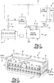
- FIG. 1 illustrates a general schematic view of a prior art fuel system 10 for an energy conversion device (ECD) 12.
- a plate-type deoxygenator system 14 receives liquid fuel F from a reservoir 16 such as a fuel tank.
- the fuel F is typically a hydrocarbon such as jet fuel.
- the ECD 12 may exist in a variety of forms in which the fuel, at some point prior to eventual use for processing, for combustion or for some form of energy release, acquires sufficient heat to support autoxidation reactions and coking if dissolved oxygen is present to any significant extent in the fuel.
- ECD 12 is a gas turbine engine, and particularly such engines in high performance aircraft.
- the fuel also serves as a coolant for one or more sub-systems in the aircraft and becomes heated as it is delivered to fuel injectors immediately prior to combustion.
- a heat exchange section 18 represents a system through which the fuel passes in a heat exchange relationship. It should be understood that the heat exchange section 18 may be directly associated with the ECD 12 and/or distributed elsewhere in the larger system 10.
- the heat exchange system 18 may alternatively or additionally include a multiple of heat exchangers distributed throughout the system. For instance a heat exchange unit 19 may be distributed upstream of the deoxygenator system 14.
- fuel F stored in the reservoir 16 normally contains an unacceptable level of dissolved oxygen therein, possibly at a saturation level as high as 70 ppm.
- a fuel pump 20 draws the fuel F from the reservoir 16.
- the fuel pump 20 communicates with the reservoir 16 via a fuel reservoir conduit 22 and a valve 24 to a fuel inlet 26 of the deoxygenator system 14.
- the pressure applied by the fuel pump 20 assists in circulating the fuel F through the deoxygenator system 14 and to other portions of the fuel system 10 including the upstream heat exchanger 19.
- oxygen is selectively removed into a sweep gas/vacuum system 28.
- the deoxygenated fuel Fd flows from a fuel outlet 30 of the deoxygenation system 14 via a deoxygenated fuel conduit 32, to the heat exchange system 18 and to the ECD 12 such as the fuel injectors of a gas turbine engine (not shown).
- a portion of the deoxygenated fuel may be recirculated, as represented by recirculation conduit 33 to either the deoxygenation system 14 and/or the reservoir 16.
- the prior art deoxygenator system 14 can include a multiple of gas/fuel micro-channel assemblies 34 which may include an oxygen permeable membrane (not shown) between a fuel channel (not shown) and an oxygen receiving channel including either a vacuum or a sweep gas (not shown).
- the channels may be of various shapes and arrangements to provide a pressure differential, which maintains an oxygen concentration differential across the membrane to deoxygenate the fuel.
- the deoxygenator system 14 includes a top plate 45 and a bottom plate 50 that are connected via bolts or other connectors 55 to the gas/fuel micro-channel assemblies 34 to maintain the rigidity of the gas/fuel micro-channel assemblies 34.
- the top plate 45 includes a conduit 57 that connects to the sweep gas/vacuum system 28.
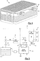
- the novel deoxygenator/heat exchanger 65 includes a heat exchanger 70 having a generally rectangular-shaped body that includes a plurality of fins 75 extending outwardly therefrom disposed atop the gas/fuel micro-channel assemblies 34 after the top plate 45 of the deoxygenator system 14 is removed.
- the heat exchanger 70 body conforms to a shape of the gas/fuel micro-channel assemblies 34.
- the fuel flows along a fuel path, which may be sinuous or have another shape, within the heat exchanger 70 under the fins 75 before entering a manifold and conduits 90 that feed the gas/fuel micro-channel assemblies 34 where oxygen is removed.
- the fuel path may be bored into the heat exchanger 70 be within an open space and finned, or be distributed across the heat exchanger 70 in every other of a series of multiple plates (see FIG. 4 ) etc.
- Fuel flowing from the fuel pump 20 flows into the fuel inlet 26 and along the sinuous path and absorbs heat collected by the heat exchanger surface 65 to raise the temperature of the fuel, in one example, to about 180°F (82°C). This temperature assists in the removal of oxygen via the gas/fuel micro-channel assemblies 34 without significantly raising a probability of created coke.
- the fuel is then sent to the upstream heat exchanger 18 and/or the ECD.
- This deoxygenator/heat exchanger 65 is designed to extract heat from ambient.
- the heat exchanger surface 70 may be placed on any portion of the deoxygenator system 14 where fuel flows before entering the gas/fuel micro-channel assemblies 34.
- top plate 45 is replaced with a heat exchanger body 100 that has an additional heat source, such as oil or heated air, input 105 and an output 110 through paths 115 that interact with fuel path(s) in plates 120 that carry fuel to transfer heat to the fuel in the plates 120.
- the air or oil may be distributed into input 105 that attaches to multiple paths through multiple plates 120 or otherwise interact with the fuel path to efficiently transfer heat to the fuel.
- FIG. 5 an embodiment of a fuel system 10 is shown.
- Many commercial airliners operate their fuel systems at about 250 degrees F or 121 degrees C to minimize coking.
- the heat exchangers 65/95 or the like By attaching the heat exchangers 65/95 or the like to the deoxygenator system 14, several advantages accrue: the fuel F captures low grade heat from ambient via fins 75 to improve the efficiency of the deoxygenator system 65/95; the heat exchanger and the deoxygenator system 65/95 are one unit and space is recovered and the amount of connections are minimized, rigidity necessary to retain the gas/fuel micro-channel assemblies 34 is maintained; installation is simplified; and the size of the downstream heat exchanger 18 may be minimized or eliminated, particularly if the heat exchanger body 100 is utilized in the deoxygenator system 65/95.
- the heat exchangers 65/95 may be placed near heat sources 120 such as an auxiliary power unit or the like to take advantage of waste heat emanating from the auxiliary power unit.
- the heat exchangers 65/95 may be required to add much more heat to the fuel (e.g. up to 400 degrees F or 204 degrees C more heat) in conjunction with or instead of the heat exchangers 18 and 19.
Landscapes
- Engineering & Computer Science (AREA)
- Chemical & Material Sciences (AREA)
- Combustion & Propulsion (AREA)
- Mechanical Engineering (AREA)
- General Engineering & Computer Science (AREA)
- Production Of Liquid Hydrocarbon Mixture For Refining Petroleum (AREA)
- Hydrogen, Water And Hydrids (AREA)
- Separation Using Semi-Permeable Membranes (AREA)
Claims (12)
- Konditionierer (65;95) zum Konditionieren von Brennstoff, der durch diesen strömt, wobei der Konditionierer (65;95) Folgendes umfasst:einen Entgaser, der einen Körper aufweist, in dem Sauerstoff aus dem Brennstoff entfernt wird, wobei der Körper eine Fläche aufweist; und,einen Wärmetauscher (70;100), der direkt an dem Körper befestigt ist und der Fläche zum Absenken einer Temperatur des Brennstoffs angepasst ist; dadurch gekennzeichnet, dass:
der Wärmetauscher (70;100) eine Vielzahl von Rippen (75) aufweist, die sich nach außen von diesem in eine Richtung weg von der Fläche erstrecken. - Konditionierer nach Anspruch 1, wobei der Wärmetauscher (70; 100) dem Körper Struktursteifigkeit bereitstellt.
- Konditionierer nach Anspruch 1 oder 2, wobei der Körper einen sinusförmigen Weg aufweist, in welchem der Brennstoff durch diesen strömt.
- Konditionierer nach einem der vorhergehenden Ansprüche, wobei der Entgaser eine Vielzahl von Gas/Brennstoff-Anordnungen (34) zum Entfernen von Sauerstoff aus diesem aufweist.
- Konditionierer nach Anspruch 4, wobei die Gas/Brennstoff-Anordnungen (34) Mikrokanäle beinhalten.
- Konditionierer nach einem der vorhergehenden Ansprüche, wobei der Wärmetauscher (70;95) aus einer Reihe von Platten besteht.
- Konditionierer nach einem der vorhergehenden Ansprüche, ferner umfassend eine Wärmequelle, die nahe dem Wärmetauscher (70;95), der an dem Körper befestigt ist, angeordnet ist.
- Konditionierer nach einem der vorhergehenden Ansprüche, wobei der Wärmetauscher (70;95) Wärme zum Brennstoff hinzugibt.
- Brennstoffsystem (10) für eine Energieumwandlungsvorrichtung (12), umfassend:einen Konditionierer (65;95) nach einem der vorhergehenden Ansprüche;keinen stromaufwärtigen Wärmetauscher, der an dem Wärmetauscher (70; 100), der direkt an dem Körper befestigt ist, befestigt ist; und,keinen stromabwärtigen Wärmetauscher, der direkt an dem Wärmetauscher (70; 100), der direkt an dem Körper befestigt ist, befestigt ist.
- Verfahren zum Konditionieren von Brennstoff in einem Brennstoffsystem:Bereitstellen eines Entgasers, der einen Körper aufweist, in welchem Sauerstoff aus dem Brennstoff entfernt wird, und eine Fläche aufweist;Befestigen eines Wärmetauschers (70;100) direkt an dem Körper und Anpassen an die Fläche zum Bereitstellen einer ersten Temperatur des Brennstoffs, wobei der Wärmetauscher (70;100) eine Vielzahl von Rippen (75) aufweist, die sich nach außen von diesem in eine Richtung weg von der Fläche erstrecken;kein Befestigen eines stromaufwärtigen Wärmetauschers an dem Wärmetauscher (70;100), der direkt an dem Körper befestigt ist; und,kein Befestigen eines stromabwärtigen Wärmetauschers an dem Wärmetauscher (70; 100), der direkt an dem Körper befestigt ist.
- Verfahren nach Anspruch 10, ferner umfassend:
Befestigen eines des stromaufwärtigen oder des stromabwärtigen Wärmetauschers an den Wärmetauscher (70; 100), der direkt an dem Körper befestigt ist, wenn eine zweite höhere Temperatur des Brennstoffs gewünscht ist. - Verfahren nach Anspruch 11, ferner umfassend:
Befestigen sowohl des stromaufwärtigen als auch des stromabwärtigen Wärmetauschers an dem Wärmetauscher (70;100), der direkt an dem Körper befestigt ist, wenn eine dritte höhere Temperatur des Brennstoffs gewünscht ist.
Applications Claiming Priority (1)
| Application Number | Priority Date | Filing Date | Title |
|---|---|---|---|
| US13/438,219 US8876946B2 (en) | 2012-04-03 | 2012-04-03 | Combined fuel stabilization unit and heat exchanger |
Publications (3)
| Publication Number | Publication Date |
|---|---|
| EP2647809A2 EP2647809A2 (de) | 2013-10-09 |
| EP2647809A3 EP2647809A3 (de) | 2016-10-12 |
| EP2647809B1 true EP2647809B1 (de) | 2020-09-23 |
Family
ID=48095577
Family Applications (1)
| Application Number | Title | Priority Date | Filing Date |
|---|---|---|---|
| EP13162219.3A Active EP2647809B1 (de) | 2012-04-03 | 2013-04-03 | Wärmetauschersystem und verfahren zu dessen betrieb |
Country Status (2)
| Country | Link |
|---|---|
| US (1) | US8876946B2 (de) |
| EP (1) | EP2647809B1 (de) |
Families Citing this family (3)
| Publication number | Priority date | Publication date | Assignee | Title |
|---|---|---|---|---|
| US9863322B2 (en) * | 2014-01-23 | 2018-01-09 | United Technologies Corporation | Selectively deoxygenated stored fuel system |
| EP3148828A1 (de) * | 2014-05-28 | 2017-04-05 | RBC Green Energy II, LLC | Luftgekühltes wärmeaustauschsystem |
| US10215097B2 (en) | 2015-12-08 | 2019-02-26 | General Electric Company | Thermal management system |
Family Cites Families (16)
| Publication number | Priority date | Publication date | Assignee | Title |
|---|---|---|---|---|
| US5162101A (en) * | 1989-01-13 | 1992-11-10 | Minntech Corporation | Oxygenator wedge configuration |
| US5124127A (en) * | 1989-01-26 | 1992-06-23 | Shiley, Incorporated | Hollow fiber blood oxygenator |
| US6939392B2 (en) * | 2003-04-04 | 2005-09-06 | United Technologies Corporation | System and method for thermal management |
| US7153343B2 (en) | 2004-03-24 | 2006-12-26 | United Technologies Corporation | Fuel deoxygenation system |
| US7431818B2 (en) | 2004-03-26 | 2008-10-07 | United Technologies Corporation | Electrochemical fuel deoxygenation system |
| US7435283B2 (en) * | 2005-05-18 | 2008-10-14 | United Technologies Corporation | Modular fuel stabilization system |
| US7465336B2 (en) | 2005-06-09 | 2008-12-16 | United Technologies Corporation | Fuel deoxygenation system with non-planar plate members |
| US7377112B2 (en) | 2005-06-22 | 2008-05-27 | United Technologies Corporation | Fuel deoxygenation for improved combustion performance |
| US7615104B2 (en) * | 2005-11-03 | 2009-11-10 | United Technologies Corporation | Fuel deoxygenation system with multi-layer oxygen permeable membrane |
| US7384452B2 (en) * | 2005-12-09 | 2008-06-10 | Praxair Technology, Inc. | Fluid heating method |
| US7571596B2 (en) | 2005-12-14 | 2009-08-11 | Hamilton Sundstrand Corporation | Vacuum system for membrane fuel stabilization unit |
| US7582137B2 (en) | 2006-01-18 | 2009-09-01 | United Technologies Corporation | Fuel deoxygenator with non-planar fuel channel and oxygen permeable membrane |
| US7824470B2 (en) | 2006-01-18 | 2010-11-02 | United Technologies Corporation | Method for enhancing mass transport in fuel deoxygenation systems |
| US20080098894A1 (en) * | 2006-11-01 | 2008-05-01 | Sabatino Daniel R | Acoustic degassing heat exchanger |
| US8234870B2 (en) | 2009-04-17 | 2012-08-07 | Hamilton Sundstrand Corporation | Additive injection system for improving thermal stability of jet fuel |
| US8177884B2 (en) | 2009-05-20 | 2012-05-15 | United Technologies Corporation | Fuel deoxygenator with porous support plate |
-
2012
- 2012-04-03 US US13/438,219 patent/US8876946B2/en active Active
-
2013
- 2013-04-03 EP EP13162219.3A patent/EP2647809B1/de active Active
Non-Patent Citations (1)
| Title |
|---|
| None * |
Also Published As
| Publication number | Publication date |
|---|---|
| US20130255489A1 (en) | 2013-10-03 |
| EP2647809A3 (de) | 2016-10-12 |
| EP2647809A2 (de) | 2013-10-09 |
| US8876946B2 (en) | 2014-11-04 |
Similar Documents
| Publication | Publication Date | Title |
|---|---|---|
| EP1731209B1 (de) | Vorrichtung zur Entfernung von Brennstoff-Sauerstoff mit Hilfe von nicht-flachen Platten | |
| EP1810737A1 (de) | Verfahren zur Verbesserung des Massentransportes bei Brennstoffentgasungssystemen | |
| US8079407B2 (en) | Integrated heat exchangers for ECS and OBIGGS applications | |
| EP2105601B1 (de) | Motorsystem | |
| EP2647809B1 (de) | Wärmetauschersystem und verfahren zu dessen betrieb | |
| US10658685B2 (en) | Integrated heat pump and fuel cell power plant | |
| CN114954965A (zh) | 具有基于二氢的冷却系统和发动机的飞行器 | |
| JP6125235B2 (ja) | 燃料電池の熱電併給システム | |
| US9927189B2 (en) | Aircraft precooler heat exchanger | |
| RU2428770C2 (ru) | Система топливных элементов и содержащая ее система водоснабжения для летательного аппарата | |
| JP2005505892A (ja) | 一体化されたカソード排気凝縮器及びスタック冷却器を組み込んだ燃料電池システム | |
| EP1782879B1 (de) | System zum Entfernen von Sauerstoff aus Treibstoff mittels einer mehrschichtigen sauerstoffpermeablen Membran | |
| US7435283B2 (en) | Modular fuel stabilization system | |
| KR20140110743A (ko) | 조수 장치 및 조수 방법 | |
| CN116265332A (zh) | 改进的预冷器 | |
| CN208655799U (zh) | 一种多电堆燃料电池热管理系统 | |
| EP3842344A1 (de) | Kraftstofftankinertisierungssystem unter verwendung von kabinenabluft | |
| AU2017222353B2 (en) | Fuel cell power plant cooling network integrated with a thermal hydraulic engine | |
| EP4454931A2 (de) | Systeme zur kühlung von notantriebsaggregaten | |
| US20060196174A1 (en) | Catalytic fuel deoxygenation system | |
| US8961891B2 (en) | Catalytic alcohol dehydrogenation heat sink for mobile application | |
| US20250382932A1 (en) | Method and apparatus for heating a flow of hydrogen | |
| US10895194B2 (en) | Cooling system, and internal combustion engine comprising a cooling system of said type | |
| EP4525105A1 (de) | Brennstoffzellensystem mit einem zwei-phasen-kühlsystem mit bypass-leitung | |
| US12448145B2 (en) | Aircraft fuel system |
Legal Events
| Date | Code | Title | Description |
|---|---|---|---|
| PUAI | Public reference made under article 153(3) epc to a published international application that has entered the european phase |
Free format text: ORIGINAL CODE: 0009012 |
|
| AK | Designated contracting states |
Kind code of ref document: A2 Designated state(s): AL AT BE BG CH CY CZ DE DK EE ES FI FR GB GR HR HU IE IS IT LI LT LU LV MC MK MT NL NO PL PT RO RS SE SI SK SM TR |
|
| AX | Request for extension of the european patent |
Extension state: BA ME |
|
| PUAL | Search report despatched |
Free format text: ORIGINAL CODE: 0009013 |
|
| AK | Designated contracting states |
Kind code of ref document: A3 Designated state(s): AL AT BE BG CH CY CZ DE DK EE ES FI FR GB GR HR HU IE IS IT LI LT LU LV MC MK MT NL NO PL PT RO RS SE SI SK SM TR |
|
| AX | Request for extension of the european patent |
Extension state: BA ME |
|
| RIC1 | Information provided on ipc code assigned before grant |
Ipc: F02C 7/22 20060101ALI20160905BHEP Ipc: F02C 3/20 20060101AFI20160905BHEP |
|
| STAA | Information on the status of an ep patent application or granted ep patent |
Free format text: STATUS: REQUEST FOR EXAMINATION WAS MADE |
|
| 17P | Request for examination filed |
Effective date: 20170412 |
|
| RBV | Designated contracting states (corrected) |
Designated state(s): AL AT BE BG CH CY CZ DE DK EE ES FI FR GB GR HR HU IE IS IT LI LT LU LV MC MK MT NL NO PL PT RO RS SE SI SK SM TR |
|
| GRAP | Despatch of communication of intention to grant a patent |
Free format text: ORIGINAL CODE: EPIDOSNIGR1 |
|
| STAA | Information on the status of an ep patent application or granted ep patent |
Free format text: STATUS: GRANT OF PATENT IS INTENDED |
|
| INTG | Intention to grant announced |
Effective date: 20200401 |
|
| GRAS | Grant fee paid |
Free format text: ORIGINAL CODE: EPIDOSNIGR3 |
|
| GRAA | (expected) grant |
Free format text: ORIGINAL CODE: 0009210 |
|
| STAA | Information on the status of an ep patent application or granted ep patent |
Free format text: STATUS: THE PATENT HAS BEEN GRANTED |
|
| AK | Designated contracting states |
Kind code of ref document: B1 Designated state(s): AL AT BE BG CH CY CZ DE DK EE ES FI FR GB GR HR HU IE IS IT LI LT LU LV MC MK MT NL NO PL PT RO RS SE SI SK SM TR |
|
| REG | Reference to a national code |
Ref country code: GB Ref legal event code: FG4D |
|
| REG | Reference to a national code |
Ref country code: CH Ref legal event code: EP |
|
| REG | Reference to a national code |
Ref country code: DE Ref legal event code: R096 Ref document number: 602013072706 Country of ref document: DE |
|
| REG | Reference to a national code |
Ref country code: IE Ref legal event code: FG4D |
|
| REG | Reference to a national code |
Ref country code: AT Ref legal event code: REF Ref document number: 1316587 Country of ref document: AT Kind code of ref document: T Effective date: 20201015 |
|
| PG25 | Lapsed in a contracting state [announced via postgrant information from national office to epo] |
Ref country code: HR Free format text: LAPSE BECAUSE OF FAILURE TO SUBMIT A TRANSLATION OF THE DESCRIPTION OR TO PAY THE FEE WITHIN THE PRESCRIBED TIME-LIMIT Effective date: 20200923 Ref country code: BG Free format text: LAPSE BECAUSE OF FAILURE TO SUBMIT A TRANSLATION OF THE DESCRIPTION OR TO PAY THE FEE WITHIN THE PRESCRIBED TIME-LIMIT Effective date: 20201223 Ref country code: SE Free format text: LAPSE BECAUSE OF FAILURE TO SUBMIT A TRANSLATION OF THE DESCRIPTION OR TO PAY THE FEE WITHIN THE PRESCRIBED TIME-LIMIT Effective date: 20200923 Ref country code: FI Free format text: LAPSE BECAUSE OF FAILURE TO SUBMIT A TRANSLATION OF THE DESCRIPTION OR TO PAY THE FEE WITHIN THE PRESCRIBED TIME-LIMIT Effective date: 20200923 Ref country code: NO Free format text: LAPSE BECAUSE OF FAILURE TO SUBMIT A TRANSLATION OF THE DESCRIPTION OR TO PAY THE FEE WITHIN THE PRESCRIBED TIME-LIMIT Effective date: 20201223 Ref country code: GR Free format text: LAPSE BECAUSE OF FAILURE TO SUBMIT A TRANSLATION OF THE DESCRIPTION OR TO PAY THE FEE WITHIN THE PRESCRIBED TIME-LIMIT Effective date: 20201224 |
|
| REG | Reference to a national code |
Ref country code: AT Ref legal event code: MK05 Ref document number: 1316587 Country of ref document: AT Kind code of ref document: T Effective date: 20200923 |
|
| PG25 | Lapsed in a contracting state [announced via postgrant information from national office to epo] |
Ref country code: LV Free format text: LAPSE BECAUSE OF FAILURE TO SUBMIT A TRANSLATION OF THE DESCRIPTION OR TO PAY THE FEE WITHIN THE PRESCRIBED TIME-LIMIT Effective date: 20200923 Ref country code: RS Free format text: LAPSE BECAUSE OF FAILURE TO SUBMIT A TRANSLATION OF THE DESCRIPTION OR TO PAY THE FEE WITHIN THE PRESCRIBED TIME-LIMIT Effective date: 20200923 |
|
| REG | Reference to a national code |
Ref country code: NL Ref legal event code: MP Effective date: 20200923 |
|
| REG | Reference to a national code |
Ref country code: LT Ref legal event code: MG4D |
|
| PG25 | Lapsed in a contracting state [announced via postgrant information from national office to epo] |
Ref country code: EE Free format text: LAPSE BECAUSE OF FAILURE TO SUBMIT A TRANSLATION OF THE DESCRIPTION OR TO PAY THE FEE WITHIN THE PRESCRIBED TIME-LIMIT Effective date: 20200923 Ref country code: CZ Free format text: LAPSE BECAUSE OF FAILURE TO SUBMIT A TRANSLATION OF THE DESCRIPTION OR TO PAY THE FEE WITHIN THE PRESCRIBED TIME-LIMIT Effective date: 20200923 Ref country code: LT Free format text: LAPSE BECAUSE OF FAILURE TO SUBMIT A TRANSLATION OF THE DESCRIPTION OR TO PAY THE FEE WITHIN THE PRESCRIBED TIME-LIMIT Effective date: 20200923 Ref country code: PT Free format text: LAPSE BECAUSE OF FAILURE TO SUBMIT A TRANSLATION OF THE DESCRIPTION OR TO PAY THE FEE WITHIN THE PRESCRIBED TIME-LIMIT Effective date: 20210125 Ref country code: NL Free format text: LAPSE BECAUSE OF FAILURE TO SUBMIT A TRANSLATION OF THE DESCRIPTION OR TO PAY THE FEE WITHIN THE PRESCRIBED TIME-LIMIT Effective date: 20200923 Ref country code: SM Free format text: LAPSE BECAUSE OF FAILURE TO SUBMIT A TRANSLATION OF THE DESCRIPTION OR TO PAY THE FEE WITHIN THE PRESCRIBED TIME-LIMIT Effective date: 20200923 Ref country code: RO Free format text: LAPSE BECAUSE OF FAILURE TO SUBMIT A TRANSLATION OF THE DESCRIPTION OR TO PAY THE FEE WITHIN THE PRESCRIBED TIME-LIMIT Effective date: 20200923 |
|
| PG25 | Lapsed in a contracting state [announced via postgrant information from national office to epo] |
Ref country code: IS Free format text: LAPSE BECAUSE OF FAILURE TO SUBMIT A TRANSLATION OF THE DESCRIPTION OR TO PAY THE FEE WITHIN THE PRESCRIBED TIME-LIMIT Effective date: 20210123 Ref country code: PL Free format text: LAPSE BECAUSE OF FAILURE TO SUBMIT A TRANSLATION OF THE DESCRIPTION OR TO PAY THE FEE WITHIN THE PRESCRIBED TIME-LIMIT Effective date: 20200923 Ref country code: ES Free format text: LAPSE BECAUSE OF FAILURE TO SUBMIT A TRANSLATION OF THE DESCRIPTION OR TO PAY THE FEE WITHIN THE PRESCRIBED TIME-LIMIT Effective date: 20200923 Ref country code: AL Free format text: LAPSE BECAUSE OF FAILURE TO SUBMIT A TRANSLATION OF THE DESCRIPTION OR TO PAY THE FEE WITHIN THE PRESCRIBED TIME-LIMIT Effective date: 20200923 Ref country code: AT Free format text: LAPSE BECAUSE OF FAILURE TO SUBMIT A TRANSLATION OF THE DESCRIPTION OR TO PAY THE FEE WITHIN THE PRESCRIBED TIME-LIMIT Effective date: 20200923 |
|
| REG | Reference to a national code |
Ref country code: DE Ref legal event code: R097 Ref document number: 602013072706 Country of ref document: DE |
|
| PG25 | Lapsed in a contracting state [announced via postgrant information from national office to epo] |
Ref country code: SK Free format text: LAPSE BECAUSE OF FAILURE TO SUBMIT A TRANSLATION OF THE DESCRIPTION OR TO PAY THE FEE WITHIN THE PRESCRIBED TIME-LIMIT Effective date: 20200923 |
|
| PLBE | No opposition filed within time limit |
Free format text: ORIGINAL CODE: 0009261 |
|
| STAA | Information on the status of an ep patent application or granted ep patent |
Free format text: STATUS: NO OPPOSITION FILED WITHIN TIME LIMIT |
|
| PG25 | Lapsed in a contracting state [announced via postgrant information from national office to epo] |
Ref country code: SI Free format text: LAPSE BECAUSE OF FAILURE TO SUBMIT A TRANSLATION OF THE DESCRIPTION OR TO PAY THE FEE WITHIN THE PRESCRIBED TIME-LIMIT Effective date: 20200923 Ref country code: DK Free format text: LAPSE BECAUSE OF FAILURE TO SUBMIT A TRANSLATION OF THE DESCRIPTION OR TO PAY THE FEE WITHIN THE PRESCRIBED TIME-LIMIT Effective date: 20200923 |
|
| 26N | No opposition filed |
Effective date: 20210624 |
|
| PG25 | Lapsed in a contracting state [announced via postgrant information from national office to epo] |
Ref country code: MC Free format text: LAPSE BECAUSE OF FAILURE TO SUBMIT A TRANSLATION OF THE DESCRIPTION OR TO PAY THE FEE WITHIN THE PRESCRIBED TIME-LIMIT Effective date: 20200923 |
|
| PG25 | Lapsed in a contracting state [announced via postgrant information from national office to epo] |
Ref country code: LU Free format text: LAPSE BECAUSE OF NON-PAYMENT OF DUE FEES Effective date: 20210403 |
|
| REG | Reference to a national code |
Ref country code: BE Ref legal event code: MM Effective date: 20210430 |
|
| PG25 | Lapsed in a contracting state [announced via postgrant information from national office to epo] |
Ref country code: LI Free format text: LAPSE BECAUSE OF NON-PAYMENT OF DUE FEES Effective date: 20210430 Ref country code: CH Free format text: LAPSE BECAUSE OF NON-PAYMENT OF DUE FEES Effective date: 20210430 |
|
| PG25 | Lapsed in a contracting state [announced via postgrant information from national office to epo] |
Ref country code: IE Free format text: LAPSE BECAUSE OF NON-PAYMENT OF DUE FEES Effective date: 20210403 |
|
| PG25 | Lapsed in a contracting state [announced via postgrant information from national office to epo] |
Ref country code: IS Free format text: LAPSE BECAUSE OF FAILURE TO SUBMIT A TRANSLATION OF THE DESCRIPTION OR TO PAY THE FEE WITHIN THE PRESCRIBED TIME-LIMIT Effective date: 20210123 |
|
| PG25 | Lapsed in a contracting state [announced via postgrant information from national office to epo] |
Ref country code: BE Free format text: LAPSE BECAUSE OF NON-PAYMENT OF DUE FEES Effective date: 20210430 |
|
| PG25 | Lapsed in a contracting state [announced via postgrant information from national office to epo] |
Ref country code: HU Free format text: LAPSE BECAUSE OF FAILURE TO SUBMIT A TRANSLATION OF THE DESCRIPTION OR TO PAY THE FEE WITHIN THE PRESCRIBED TIME-LIMIT; INVALID AB INITIO Effective date: 20130403 |
|
| P01 | Opt-out of the competence of the unified patent court (upc) registered |
Effective date: 20230522 |
|
| PG25 | Lapsed in a contracting state [announced via postgrant information from national office to epo] |
Ref country code: CY Free format text: LAPSE BECAUSE OF FAILURE TO SUBMIT A TRANSLATION OF THE DESCRIPTION OR TO PAY THE FEE WITHIN THE PRESCRIBED TIME-LIMIT Effective date: 20200923 |
|
| PG25 | Lapsed in a contracting state [announced via postgrant information from national office to epo] |
Ref country code: MK Free format text: LAPSE BECAUSE OF FAILURE TO SUBMIT A TRANSLATION OF THE DESCRIPTION OR TO PAY THE FEE WITHIN THE PRESCRIBED TIME-LIMIT Effective date: 20200923 |
|
| PG25 | Lapsed in a contracting state [announced via postgrant information from national office to epo] |
Ref country code: TR Free format text: LAPSE BECAUSE OF FAILURE TO SUBMIT A TRANSLATION OF THE DESCRIPTION OR TO PAY THE FEE WITHIN THE PRESCRIBED TIME-LIMIT Effective date: 20200923 |
|
| PG25 | Lapsed in a contracting state [announced via postgrant information from national office to epo] |
Ref country code: MT Free format text: LAPSE BECAUSE OF FAILURE TO SUBMIT A TRANSLATION OF THE DESCRIPTION OR TO PAY THE FEE WITHIN THE PRESCRIBED TIME-LIMIT Effective date: 20200923 |
|
| PGFP | Annual fee paid to national office [announced via postgrant information from national office to epo] |
Ref country code: FR Payment date: 20250319 Year of fee payment: 13 |
|
| PGFP | Annual fee paid to national office [announced via postgrant information from national office to epo] |
Ref country code: IT Payment date: 20250319 Year of fee payment: 13 Ref country code: GB Payment date: 20250319 Year of fee payment: 13 |
|
| PGFP | Annual fee paid to national office [announced via postgrant information from national office to epo] |
Ref country code: DE Payment date: 20250319 Year of fee payment: 13 |