EP2647794A1 - CMC blade with pressurized internal cavity for erosion control and corresponding method - Google Patents
CMC blade with pressurized internal cavity for erosion control and corresponding method Download PDFInfo
- Publication number
- EP2647794A1 EP2647794A1 EP13153323.4A EP13153323A EP2647794A1 EP 2647794 A1 EP2647794 A1 EP 2647794A1 EP 13153323 A EP13153323 A EP 13153323A EP 2647794 A1 EP2647794 A1 EP 2647794A1
- Authority
- EP
- European Patent Office
- Prior art keywords
- airfoil
- blade
- cavities
- fluid
- interior
- Prior art date
- Legal status (The legal status is an assumption and is not a legal conclusion. Google has not performed a legal analysis and makes no representation as to the accuracy of the status listed.)
- Granted
Links
Images




Classifications
-
- F—MECHANICAL ENGINEERING; LIGHTING; HEATING; WEAPONS; BLASTING
- F01—MACHINES OR ENGINES IN GENERAL; ENGINE PLANTS IN GENERAL; STEAM ENGINES
- F01D—NON-POSITIVE DISPLACEMENT MACHINES OR ENGINES, e.g. STEAM TURBINES
- F01D5/00—Blades; Blade-carrying members; Heating, heat-insulating, cooling or antivibration means on the blades or the members
- F01D5/12—Blades
- F01D5/14—Form or construction
- F01D5/18—Hollow blades, i.e. blades with cooling or heating channels or cavities; Heating, heat-insulating or cooling means on blades
- F01D5/181—Blades having a closed internal cavity containing a cooling medium, e.g. sodium
-
- F—MECHANICAL ENGINEERING; LIGHTING; HEATING; WEAPONS; BLASTING
- F01—MACHINES OR ENGINES IN GENERAL; ENGINE PLANTS IN GENERAL; STEAM ENGINES
- F01D—NON-POSITIVE DISPLACEMENT MACHINES OR ENGINES, e.g. STEAM TURBINES
- F01D21/00—Shutting-down of machines or engines, e.g. in emergency; Regulating, controlling, or safety means not otherwise provided for
- F01D21/003—Arrangements for testing or measuring
-
- F—MECHANICAL ENGINEERING; LIGHTING; HEATING; WEAPONS; BLASTING
- F01—MACHINES OR ENGINES IN GENERAL; ENGINE PLANTS IN GENERAL; STEAM ENGINES
- F01D—NON-POSITIVE DISPLACEMENT MACHINES OR ENGINES, e.g. STEAM TURBINES
- F01D5/00—Blades; Blade-carrying members; Heating, heat-insulating, cooling or antivibration means on the blades or the members
- F01D5/12—Blades
- F01D5/14—Form or construction
- F01D5/147—Construction, i.e. structural features, e.g. of weight-saving hollow blades
-
- F—MECHANICAL ENGINEERING; LIGHTING; HEATING; WEAPONS; BLASTING
- F01—MACHINES OR ENGINES IN GENERAL; ENGINE PLANTS IN GENERAL; STEAM ENGINES
- F01D—NON-POSITIVE DISPLACEMENT MACHINES OR ENGINES, e.g. STEAM TURBINES
- F01D5/00—Blades; Blade-carrying members; Heating, heat-insulating, cooling or antivibration means on the blades or the members
- F01D5/12—Blades
- F01D5/14—Form or construction
- F01D5/18—Hollow blades, i.e. blades with cooling or heating channels or cavities; Heating, heat-insulating or cooling means on blades
-
- F—MECHANICAL ENGINEERING; LIGHTING; HEATING; WEAPONS; BLASTING
- F01—MACHINES OR ENGINES IN GENERAL; ENGINE PLANTS IN GENERAL; STEAM ENGINES
- F01D—NON-POSITIVE DISPLACEMENT MACHINES OR ENGINES, e.g. STEAM TURBINES
- F01D5/00—Blades; Blade-carrying members; Heating, heat-insulating, cooling or antivibration means on the blades or the members
- F01D5/12—Blades
- F01D5/14—Form or construction
- F01D5/18—Hollow blades, i.e. blades with cooling or heating channels or cavities; Heating, heat-insulating or cooling means on blades
- F01D5/187—Convection cooling
-
- F—MECHANICAL ENGINEERING; LIGHTING; HEATING; WEAPONS; BLASTING
- F05—INDEXING SCHEMES RELATING TO ENGINES OR PUMPS IN VARIOUS SUBCLASSES OF CLASSES F01-F04
- F05D—INDEXING SCHEME FOR ASPECTS RELATING TO NON-POSITIVE-DISPLACEMENT MACHINES OR ENGINES, GAS-TURBINES OR JET-PROPULSION PLANTS
- F05D2300/00—Materials; Properties thereof
- F05D2300/60—Properties or characteristics given to material by treatment or manufacturing
- F05D2300/603—Composites; e.g. fibre-reinforced
- F05D2300/6033—Ceramic matrix composites [CMC]
-
- Y—GENERAL TAGGING OF NEW TECHNOLOGICAL DEVELOPMENTS; GENERAL TAGGING OF CROSS-SECTIONAL TECHNOLOGIES SPANNING OVER SEVERAL SECTIONS OF THE IPC; TECHNICAL SUBJECTS COVERED BY FORMER USPC CROSS-REFERENCE ART COLLECTIONS [XRACs] AND DIGESTS
- Y02—TECHNOLOGIES OR APPLICATIONS FOR MITIGATION OR ADAPTATION AGAINST CLIMATE CHANGE
- Y02T—CLIMATE CHANGE MITIGATION TECHNOLOGIES RELATED TO TRANSPORTATION
- Y02T50/00—Aeronautics or air transport
- Y02T50/60—Efficient propulsion technologies, e.g. for aircraft
-
- Y—GENERAL TAGGING OF NEW TECHNOLOGICAL DEVELOPMENTS; GENERAL TAGGING OF CROSS-SECTIONAL TECHNOLOGIES SPANNING OVER SEVERAL SECTIONS OF THE IPC; TECHNICAL SUBJECTS COVERED BY FORMER USPC CROSS-REFERENCE ART COLLECTIONS [XRACs] AND DIGESTS
- Y10—TECHNICAL SUBJECTS COVERED BY FORMER USPC
- Y10T—TECHNICAL SUBJECTS COVERED BY FORMER US CLASSIFICATION
- Y10T29/00—Metal working
- Y10T29/49—Method of mechanical manufacture
- Y10T29/49316—Impeller making
- Y10T29/49336—Blade making
- Y10T29/49337—Composite blade
Definitions
- the present invention relates to ceramic matrix composite ("CMC") blades for gas turbine engines used in the power generation and aircraft industries and, in particular, to a new form of CMC blade maintained under a fixed pressure to prevent the blade cavities from being compromised (which otherwise could lead to a catastrophic failure of the engine) due to foreign object damage occurring to the blades during extended periods of use.
- CMC ceramic matrix composite
- CMCs ceramic matrix composites
- PIP polymer infiltration and pyrolysis
- MI slurry cast melt infiltration
- edge protection strips allow the energy of impact (due, for example, to a bird strike) to be transmitted down to the trailing edge of the blade.
- the dissipation of the impact energy can cause the blade to locally oscillate and/or be displaced to a different amplitude, and ultimately fail.
- Any oscillations or large rapid displacements of the trailing edge also induce strains to the blade matrix which can exceed material system limits and create internal delamination and/or blade surface fracture. Objects impacting a blade can even lead to the loss of edge material and rotor imbalance which in turn limits engine speed and power.
- CMC materials are highly resistant to hot temperatures (much more than metals), water vapor in exhaust streams can cause rapid degradation of the matrix, and thus the materials must normally be coated with an environmental barrier coating ("EBC") in order to protect the underlying matrix from water vapor present in the combustion stream.
- EBC environmental barrier coating
- thermal coatings on CMC components cannot prevent breaches to the turbine blade itself due to objects impacting against the blades during operation, particularly along the leading edge.
- any penetration of the EBC occurs due to foreign object damage, or by other means such as thermo mechanical shock, the underlying CMC material faces accelerated degradation due to an increased exposure to any water in the hot gas path.
- the present invention includes a new type of airfoil and CMC blade for use in a gas turbine engine having a design that ensures greater longevity, particularly in the event of damage to an airfoil caused by a foreign object impacting the blade.
- the invention provides a unique method of secondary blade protection by using dry, cool air to protect the structural integrity of the blade even after an initial penetration of the CMC matrix.
- cool to describe the air used to pressurize and preserve the internal cavities of rotor blades means a supply of air at temperatures well below the normal temperature of the gas turbine exhaust and typically well below 900°F.
- blade includes the airfoil portion, a blade shank, dovetail connection and blade platform.
- the exemplary CMC blades described herein include a curved airfoil (sometimes referred to as a gas turbine “bucket") having leading and trailing edges and pressure and suction side surfaces, a blade shank secured to the lower end of the airfoil, one or more interior fluid cavities disposed within the airfoil such that each interior fluid cavity is sealed, an inlet fluid passage at the lower end in fluid communication with the blade shank, one or more fluid passageways formed in the blade shank corresponding to each one of the interior fluid cavities, and a fluid pump and/or compressor for continuously providing a source of pressurized fluid (nominally cool, dry air) to each one of the interior fluid cavities in each airfoil.
- a source of pressurized fluid nominally cool, dry air
- the source of cool, dry air is sufficient in pressure and volume to maintain a minimum continuous air flow to each of the interior fluid cavities as described above in the event of a breach of one or more cavities due to foreign object impact or other damage.
- the method according to the invention serves to extend the life of critical engine components, particularly the rotor blades, that may suffer from damage during operation that otherwise could result in a catastrophic engine failure.
- the CMC blades according to the invention can be manufactured using a CMC matrix composite fabrication process known as a "hollow fashion.”
- the blades are formed with at least one, and preferably multiple, integral interior sealed cavities, with each cavity having an opening at the lower end in the blade shank.
- the interior cavities extend substantially the entire length of the composite blade to form one or more integral blade chambers.
- Each blade also has an air entry passage that feeds directly into each of the respective blade cavities.
- the blade cavity is not compromised by the ingression of hot and moist combustion air originating from the turbine flow path.
- the air nominally is ported directly into the blade using an adapter piece and fluid openings in the blade shank.
- the system is also designed to accommodate and continuously control any leakage due to object impact in order to prevent further blade deterioration and/or a catastrophic failure of the blade or possibly the entire engine.
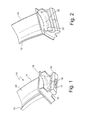
- FIG. 1 depicts an exemplary embodiment of a CMC composite turbine blade having an integral interior blade cavity pressurization means according to the invention, referred to herein as "bottom feed blade pressurization.”
- the curved blade (as used in many gas turbine engines) is depicted generally at 10 and includes a leading edge 11 and trailing edge 12.
- the "blade” includes the entire article comprising an airfoil portion 23 (which receives hot exhaust gas from the gas turbine engine), the blade shank 15, dovetail connection 14 and blade platform 16.
- the curved configuration of the blade provides for pressure and suction side surfaces of the airfoil extending between the leading and trailing edges.
- Exemplary airfoils can be produced by various CMC fabrication techniques which involve forming a preform of ceramic fiber (such as silicon carbide) in the desired shape by weaving or other known fabrication methods, and then infiltrating the preform with a matrix material.
- the preform can be coated for bonding with the matrix, e.g., using chemical vapor infiltration, slurry infiltration-sintering, slurry casting or melt infiltration.
- blade 10 can be configured for use in other blade assemblies such as a compressor or any other suitable fan blade application.
- the assembly includes one or more blades 10 formed from a ceramic matrix composite material, such as silicon carbide fibers embedded in a silicon carbide matrix ("SiC/SiC").
- Blade 10 includes airfoil 12 against which the flow of hot exhaust gas is directed with the airfoil being mounted to a turbine wheel disk (not shown) by dovetail 14 extending downwardly from airfoil 12 and engaging a slot in a corresponding geometry of the gas turbine wheel disk. Dovetail 14 and the surfaces of airfoil 12 thereby form a concave intersection as shown.
- blade 10 may include a geometry corresponding to other turbine applications.
- the plurality of turbine blades 10 are secured to a turbine rotor wheel disk (not shown) by means of dovetail 14. See also FIG. 9 .
- the blade airfoils or buckets extend a full 360 degrees about the turbine wheel forming an entire row of buckets.
- Each dovetail joint includes a shaped slot formed in the dovetail portion designed for mating and sliding engagement with a complementary dovetail shape formed on the rim of the rotor wheel.
- the buckets are designed to be added to the rotor wheel via a radial filling slot formed in the wheel rim, i.e., by moving a bucket radially into the slot and then sliding the bucket tangentially along the dovetail tang. This process is repeated until an entire row of buckets are mounted on the wheel.
- the entire CMC blade includes integral platform 16 extending across the pressure side and the suction side of dovetail 14.
- FIG. 1 also illustrates exemplary means for pressurizing the integral interior blade cavities in a first embodiment of the invention via fluid openings 17 and 18.
- This type of bottom feed pressurization can be achieved by introducing a continuous air stream (ultimately creating a steady state internal pressure condition) into each blade cavity through blade openings 17 and 18 (see also FIGS. 3 and 4 ).
- the two air feeds extend from the bottom edge of the blade dovetail up through blade shank 15 into the CMC cavities.
- pressurized air nominally is provided by an external pressure system ( see FIG. 8 ).
- FIG. 2 is a perspective view of a CMC composite turbine blade having an alternative integral interior blade cavity pressurization system in a second embodiment as compared to FIG.1 .
- This shank-fed blade pressurization system provides a continuous air stream using separate internal feed passageways beginning in the blade shank and proceeding into the separate blade cavities as shown. Again, the air feed ultimately forms a steady state internal pressure condition in each blade cavity. However, in this embodiment the flow occurs via smaller blade air passageways 35 and 37.
- the separate air feed lines extend from the bottom edge of the blade dovetail up through the blade shank into the separate CMC cavities.
- the pressurized air is again provided by an external air pressure system.
- the embodiment of FIG. 2 utilizes the same basic curved blade design with generally congruent interior cavities as in FIG. 1 , with leading edge 11 and trailing edge 12.
- FIG. 3 is a front elevation view of the composite CMC turbine blade 10 depicted in FIG. 1 further illustrating the fluid passageways for achieving interior blade cavity pressurization according to the invention.
- This embodiment includes blade airfoil 23 and two interior blade cavities 13 and 24, with cavity 13 defined by interior side walls 19 and 20 and cavity 24 formed by side walls 21 and 22.
- Inlet fluid passages 17 and 18 feed pressurized air directly into the cavities via openings as shown.
- FIG. 3 also includes dovetail connection 14 and blade shank 15 described above in connection with FIG. 1 .
- cavities 13 and 24 do not allow for the continuous flow of air into or through the cavities, and thus the blade remains at a relatively constant, steady-state pressure even if a minor breach occurs to the blade exterior due to impact with an external object.
- FIG. 4 depicts a front elevation view of the CMC composite turbine blade in FIG. 2 , further illustrating the fluid passageways for achieving interior blade cavity pressurization according to the invention.
- Fluid passageways 34 and 36 receive pressured cool air from an external source (not shown) via fluid entry points 35 and 37, which in turn feed directly into interior blade cavities 32 and 33. Again, the air flow results in a steady-state, pressurized environment inside the airfoil 30 to protect against the adverse effect of breaches to the CMC composite blade caused by high velocity exterior object impact.
- Interior blade cavities 32 and 33 can extend substantially the entire length of the airfoil or, alternatively, to a portion of the airfoil, thereby defining a localized blade cavity corresponding to a predicted area of potential damage to the airfoil.
- FIG. 5 is a perspective view of an exemplary CMC composite turbine blade having the integral interior blade cavity pressurization system according to the invention depicting the separate, integral interior cavities and pressurization flow channels of the embodiment in FIG. 2 .
- the same reference numbers have been assigned to comparable blade components in FIG. 5 , i.e., depicting interior fluid passageways 34 and 36 with air entry feed points 35 and 37 and with the fluid passageways feeding directly into the interior blade cavities 32 and 33.
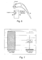
- FIG. 6 is a graphical representation of the predicted progression of hot gas path damage degradation to an uncoated CMC blade as compared to the predicted degradation using an exemplary cavity pressurization system of the invention.
- the impact on the leading edge (“LE") from an exterior object results in damage to the CMC composite blade material as shown. Nominally, even assuming that a breach occurs to the interior of one of the blade cavities, the pressurized system will ensure the continued structural integrity of the blade by maintaining a substantially constant air pressure inside the cavities following an impact. In addition, the pressurization prevents any influx of water vapor into the blade interior which otherwise would accelerate blade degradation.
- a plurality of impact sensors can also be positioned at strategic positions on the surface of the blade leading edge, together with feedback control means to indicate the relative size and location of a breach immediately after it occurs.
- FIG. 7 depicts the cross section of an exemplary gas turbine airfoil indicating the nature and location of exemplary impact damage to be contained and controlled using the pressurization systems described above.
- FIG. 7 compares the amount of blade degradation in the form of a breach to the CMC composite blade interior in inches to the corresponding predicted amount of hot gas path degradation, ranging from a degradation amount that is only a fraction of the maximum possible degradation of an opening along the leading edge of the CMC blade, i.e., the area of potential damage without the benefit of an interior fluid cavity pressurization system according to the invention.
- FIG. 7 thus shows the general orders of magnitude of increased recession of the CMC material as the hot gas path degradation continues over time.
- the unprotected CMC recession could be up to 20 times greater than a recession protected by the new fluid cavity pressurization described above.
- FIG. 7 also provides a direct comparison to the compressed air leakage degradation that can be anticipated over time following an impact, and thus illustrates how the invention protects against otherwise inevitable increases in blade degradation and ensures that the gas turbine engine can continue to operate until a normal maintenance shutdown occurs.
- FIG. 8 is a simplified process flow diagram for achieving the desired level of pressurization of CMC composite blades in a gas turbine engine. Cooling air supplied by an external air compressor system feeds directly into the individual blade cavities 43 and 53 in CMC composite blades 40, 50 and 60 in the manner described above, in this case using interior flow passages 44 and 54 from the compressor system through air feed lines 45 and 55, respectively. FIG. 8 also shows the general direction of hot gas flow into the leading edges of blade cavities 43 and 53. As noted above, in the absence of a breach to the integrity of the blade, the air being used to pressurize blade cavity will not flow into the turbine exhaust during normal operation.
- FIG. 9 is a cross-sectional view of a gas turbine rotor assembly depicting the flow profile using an exemplary pressure system according to the invention as described above in connection with FIGs. 3-5 and 8 .
- FIG. 9 also depicts the location of pressure transducers used to detect the location of a breach in the structural integrity of an airfoil.
- FIG. 9 includes a plurality of circumferentially-spaced hollow CMC matrix blades (shown by way of example as rotor airfoils 74 and 77), each of which includes one or more interior cavities capable of being protected as described above, i.e., with pressurized interior rotor airfoil cavities 70 and 73 depicted below stator blades 75 and 79.
- Each of the rotor airfoils connects directly to a corresponding shank, with the lower blade section coupled to plenum 78.
- a typical rotor assembly such as that shown in FIG. 9 also includes first, second and third stage wheel disks as shown, by way of example, as wheel disks 100, 102 and 103, with spacers between disks and the rotor blades fitted to the outer peripheries of a corresponding wheel disk.
- the wheel disks and rotor blades define a series of fluid passages 106, 107, 108 and 109 sufficient in size to accommodate pressurized, cool air being fed to the individual blades as described above in connection with FIGS. 3-5 .
- the pressurized air passes through the fluid passages into and through air channels 104 and 105 formed between the fluid passages and inner walls of the blade interior cavities.
- FIG. 9 also shows the locations of exemplary pressure transducers positioned at various locations within the rotor assembly for purposes of determining the existence and extent of any breach to the integrity of one or more airfoil interiors.
- the pressure transducers are installed at rotor assembly positions 80, 81, 83 and 85 through 91 as shown (generally at or near the pressurization circuit itself), as well as stator pressure transducer positions 76, 92 and 93. Together, the transducers provide continuous feedback data regarding a breach of one or more individual airfoils at the locations indicated.
- the static (non-flowing) air pressure inside the airfoils e.g., rotor blade cavities 70 and 73
- the pressure signals at the transducers will change accordingly.
- a significant failure due to an object impact on the airfoil if left undetected, creates a significant risk of collateral damage to the entire engine.
- cooling fluid will flow out of the airfoil through the breach, decreasing the static pressure.
- An exemplary system for detecting a failure of an airfoil thus includes one or more sensors that provide signals responsive to a condition of flow of cooling fluid out of an airfoil cavity as compared to a static, steady-state pressure.
- sensors may be used and include devices capable of measuring flow, fluid velocity, dynamic pressure, static pressure, temperature or other parameters responsive to a condition of fluid flowing out of an airfoil cavity.
- Pressure transducers useful in practicing the invention include those available from Sensonetics, such as the SEN-400 "Melt Pressure Transducer" manufactured using silicon-on-Sapphire technology having a frequency response of about 4,000 HZ, normally with an infinite resolution, sapphire wetted material and adaptable for use in variable pressure ranges.
- Other examples of acceptable transducers include, but are not limited to, Pitot tubes, static tubes, 5-hole probes, hot wire anemometers, static pressure sensors and dynamic pressure sensors.
- the system depicted in FIG. 9 will also normally include a data storage device such as a hard drive or solid-state memory for storing executable instructions in the form of a computer code capable of correlating any detected change in pressure transducer signals and report a condition of failure of a specific airfoil cavity.
- a central processing unit operative with the computer code correlates the change in signals resulting from a breach due to object impact.
- the computer code may initiate further process steps to identify the exact breach location, such as at the leading edge or other locations with external pressure loads on the airfoil.
- An output device responsive to the output signals provides an indication of the condition of failure, such as a warning light, an acoustic warning signal or a warning message in a data recorder.
- FIG. 10 is a graphical representation of a typical plot of an interior cavity pressure signal plotted over time as the gas turbine engine continues to operate and illustrates a potential failure mode for a given airfoil. Normally, several pressure transducers are located within the same circuit. FIG. 10 also illustrates that when a particular pressure differential is detected (labeled "Event"), an alarm signal will be generated due to increased cooling flow through the circuit as noted above.
- Event a particular pressure differential is detected
Landscapes
- Engineering & Computer Science (AREA)
- Mechanical Engineering (AREA)
- General Engineering & Computer Science (AREA)
- Architecture (AREA)
- Turbine Rotor Nozzle Sealing (AREA)
- Structures Of Non-Positive Displacement Pumps (AREA)
Abstract
Description
- The present invention relates to ceramic matrix composite ("CMC") blades for gas turbine engines used in the power generation and aircraft industries and, in particular, to a new form of CMC blade maintained under a fixed pressure to prevent the blade cavities from being compromised (which otherwise could lead to a catastrophic failure of the engine) due to foreign object damage occurring to the blades during extended periods of use.
- Over the years, the performance criteria of gas turbine engines has steadily increased with corresponding improvements in engine efficiency, better thrust-to-weight ratios, lower emissions and improved fuel consumption. However, gas turbine engine temperatures often reach or exceed the limits of the materials of construction, thereby comprising the structural integrity of components in the hot sections of the engine, particularly the gas turbine engine blades. Thus, as gas turbine operating temperatures have increased, various methods have been developed to help protect blades in both the rotor and turbine sections using, for example, high temperature alloys for the combustors and turbine blades. Initially, ceramic thermal barrier coatings ("TBCs") were applied to the surfaces of components exposed to the hot effluent combustion gases in order to reduce the heat transfer rate and provide thermal protection to the underlying metal and allow components. Such improvements helped to reduce the peak temperatures and thermal gradients of the base metal.
- In more recent times, ceramic matrix composites ("CMCs") were developed as substitutes for many of the high temperature alloys used in conventional turbine engines. CMCs offered improved temperature capability and density advantages over metal blades, often making them the material of choice at the higher anticipated operating temperatures of newer generation turbine engines. A number of new manufacturing techniques have also been developed to produce better quality engine components, particularly the turbine blades, using CMC construction materials. For example, silicon carbide CMCs are now formed from fibrous material infiltrated with molten silicon, such as products made by the "Silcomp" process. Other techniques for forming CMC components include polymer infiltration and pyrolysis ("PIP") and the slurry cast melt infiltration ("MI") process. All such processes focus on improving the structural integrity of gas engine components without sacrificing engine performance.
- The efforts to develop improved composite rotor blades, stator vanes and airfoils having high strength with elongated filaments composited in a light weight matrix continues to this day. One problem that has discouraged the introduction of new light weight composite gas turbine engine blades is their relative vulnerability to foreign object damage. Many types and sizes of foreign objects can become entrained in the inlet of a gas turbine engine, particularly aircraft engines, ranging from birds to hailstones, sand and dust particles. Turbine damage from foreign objects typically takes two forms. Smaller objects can erode the CMC blade material and eventually reduce the efficiency and degrade the performance of the engine. Any impact by larger objects can rupture or pierce the blades, and portions of an impacted blade can even be torn loose and cause extensive secondary damage to adjacent and downstream blades or other vital engine components. The consequences of foreign object damage appear to be greatest in the low pressure compressors of high bypass gas turbine engines.
- Various design improvements have been attempted in an effort to prevent composite blade failures due to foreign objects, such as the inclusion of a protective leading edge blade strip which helps prevent a catastrophic blade failure while providing some erosion protection to the blade, particularly along the leading edge. The edge protection strips allow the energy of impact (due, for example, to a bird strike) to be transmitted down to the trailing edge of the blade. However, even the dissipation of the impact energy can cause the blade to locally oscillate and/or be displaced to a different amplitude, and ultimately fail. Any oscillations or large rapid displacements of the trailing edge also induce strains to the blade matrix which can exceed material system limits and create internal delamination and/or blade surface fracture. Objects impacting a blade can even lead to the loss of edge material and rotor imbalance which in turn limits engine speed and power.
- Even though CMC materials are highly resistant to hot temperatures (much more than metals), water vapor in exhaust streams can cause rapid degradation of the matrix, and thus the materials must normally be coated with an environmental barrier coating ("EBC") in order to protect the underlying matrix from water vapor present in the combustion stream. Unfortunately, the use of thermal coatings on CMC components cannot prevent breaches to the turbine blade itself due to objects impacting against the blades during operation, particularly along the leading edge. Thus, if any penetration of the EBC occurs due to foreign object damage, or by other means such as thermo mechanical shock, the underlying CMC material faces accelerated degradation due to an increased exposure to any water in the hot gas path.
- A significant design problem therefore remains in the gas turbine engine field with respect to the use of ceramic matrix composites in the hot gas path. Although adding a barrier coating (EBC) helps to seal the matrix and protect it from hot gas attack, the problem of foreign object damage remains, particularly impacts that penetrate the coating. As detailed below, a new form of ceramic matrix composite blade has been developed as a significant step change in improving the long-term reliability of both blade and engine performance.
- The present invention includes a new type of airfoil and CMC blade for use in a gas turbine engine having a design that ensures greater longevity, particularly in the event of damage to an airfoil caused by a foreign object impacting the blade. The invention provides a unique method of secondary blade protection by using dry, cool air to protect the structural integrity of the blade even after an initial penetration of the CMC matrix. As used herein, the term "cool" to describe the air used to pressurize and preserve the internal cavities of rotor blades means a supply of air at temperatures well below the normal temperature of the gas turbine exhaust and typically well below 900°F. As used herein, the term "blade" includes the airfoil portion, a blade shank, dovetail connection and blade platform.
- The exemplary CMC blades described herein include a curved airfoil (sometimes referred to as a gas turbine "bucket") having leading and trailing edges and pressure and suction side surfaces, a blade shank secured to the lower end of the airfoil, one or more interior fluid cavities disposed within the airfoil such that each interior fluid cavity is sealed, an inlet fluid passage at the lower end in fluid communication with the blade shank, one or more fluid passageways formed in the blade shank corresponding to each one of the interior fluid cavities, and a fluid pump and/or compressor for continuously providing a source of pressurized fluid (nominally cool, dry air) to each one of the interior fluid cavities in each airfoil.
- Significantly, the source of cool, dry air is sufficient in pressure and volume to maintain a minimum continuous air flow to each of the interior fluid cavities as described above in the event of a breach of one or more cavities due to foreign object impact or other damage. As such, the method according to the invention serves to extend the life of critical engine components, particularly the rotor blades, that may suffer from damage during operation that otherwise could result in a catastrophic engine failure.
- The CMC blades according to the invention can be manufactured using a CMC matrix composite fabrication process known as a "hollow fashion." The blades are formed with at least one, and preferably multiple, integral interior sealed cavities, with each cavity having an opening at the lower end in the blade shank. The interior cavities extend substantially the entire length of the composite blade to form one or more integral blade chambers. Each blade also has an air entry passage that feeds directly into each of the respective blade cavities.
- Unlike known prior art CMC matrix blade and metal designs, no exit air passage is provided from the blades, and thus the cavities do not allow for the flow of air into or through the cavities in the absence of foreign object damage. Instead, the blade becomes pressurized by a source of cool, dry air and remains pressurized and stable even after an initial breach. The pressure differential between the inner and outer sections of the blade will still be sufficient to ensure a continuous (and detectable) flow of air from a pressurized source into the blade cavities if any portion of the blade (particularly along the leading edge) becomes compromised due to penetration into one or more of the internal cavities due to an impact event on the blade. By having the cool air and dry air from the rotor cavity continuously discharged, the blade cavity is not compromised by the ingression of hot and moist combustion air originating from the turbine flow path. The air nominally is ported directly into the blade using an adapter piece and fluid openings in the blade shank. The system is also designed to accommodate and continuously control any leakage due to object impact in order to prevent further blade deterioration and/or a catastrophic failure of the blade or possibly the entire engine.
- Embodiments of the present invention will now be described, by way of example only, with reference to the accompanying drawings in which:
-
FIG. 1 is a perspective view of a CMC composite turbine blade having an exemplary integral interior blade cavity pressurization system according to a first embodiment of the invention (referred to herein as "bottom feed blade pressurization"); -
FIG. 2 is a perspective view of a CMC composite turbine blade having an alternative integral interior blade cavity pressurization system (referred to herein as "shank fed blade pressurization"); -
FIG. 3 is a front elevation view of the composite CMC turbine blade depicted inFIG. 1 further illustrating exemplary fluid passageways for achieving interior blade cavity pressurization according to the invention; -
FIG. 4 is a front elevation view of the composite CMC turbine blade depicted inFIG. 2 further illustrating the alternative fluid passageways for achieving interior blade cavity pressurization; -
FIG. 5 is a perspective view of an exemplary CMC composite turbine blade having an integral interior blade cavity pressurization system and depicting the separate interior cavities and pressurization flow channels of theFIG 2 embodiment. -
FIG. 6 depicts the cross section of a gas turbine airfoil indicating the nature and location of possible impact damage that can be contained and controlled using the pressurization system described herein; -
FIG. 7 is a graphical representation of the predicted progression of hot gas path damage degradation to a CMC blade as compared to the predicted degradation using the cavity pressurization system according to the invention; -
FIG. 8 is a simplified process flow diagram for achieving the desired level of pressurization of CMC composite blades in a gas turbine engine according to the invention; -
FIG. 9 is a cross-sectional view of an exemplary gas turbine rotor assembly depicting a nominal flow profile for use with the internal cavity pressure system described in connection with other figures, particularlyFIGS. 3-5 and8 , and illustrating the use of exemplary pressure transducers positioned at different locations within a rotor assembly; and -
FIG. 10 is a graphical representation of an interior cavity pressure signal recorded over time as the gas turbine engine continues to operate and illustrating a potential failure mode for a given turbine blade after a breach occurs due to object impact. - Referring to the figures,
FIG. 1 depicts an exemplary embodiment of a CMC composite turbine blade having an integral interior blade cavity pressurization means according to the invention, referred to herein as "bottom feed blade pressurization." The curved blade (as used in many gas turbine engines) is depicted generally at 10 and includes a leadingedge 11 andtrailing edge 12. The "blade" includes the entire article comprising an airfoil portion 23 (which receives hot exhaust gas from the gas turbine engine), theblade shank 15,dovetail connection 14 andblade platform 16. The curved configuration of the blade provides for pressure and suction side surfaces of the airfoil extending between the leading and trailing edges. Exemplary airfoils can be produced by various CMC fabrication techniques which involve forming a preform of ceramic fiber (such as silicon carbide) in the desired shape by weaving or other known fabrication methods, and then infiltrating the preform with a matrix material. The preform can be coated for bonding with the matrix, e.g., using chemical vapor infiltration, slurry infiltration-sintering, slurry casting or melt infiltration. - Although the exemplary blade depicted in
FIG. 1 could be used in a gas turbine engine,blade 10 can be configured for use in other blade assemblies such as a compressor or any other suitable fan blade application. The assembly includes one ormore blades 10 formed from a ceramic matrix composite material, such as silicon carbide fibers embedded in a silicon carbide matrix ("SiC/SiC").Blade 10 includesairfoil 12 against which the flow of hot exhaust gas is directed with the airfoil being mounted to a turbine wheel disk (not shown) bydovetail 14 extending downwardly fromairfoil 12 and engaging a slot in a corresponding geometry of the gas turbine wheel disk.Dovetail 14 and the surfaces ofairfoil 12 thereby form a concave intersection as shown. In other embodiments,blade 10 may include a geometry corresponding to other turbine applications. - In the embodiment of
FIG. 1 , the plurality ofturbine blades 10 are secured to a turbine rotor wheel disk (not shown) by means ofdovetail 14. See alsoFIG. 9 . Typically, the blade airfoils or buckets extend a full 360 degrees about the turbine wheel forming an entire row of buckets. Each dovetail joint includes a shaped slot formed in the dovetail portion designed for mating and sliding engagement with a complementary dovetail shape formed on the rim of the rotor wheel. The buckets are designed to be added to the rotor wheel via a radial filling slot formed in the wheel rim, i.e., by moving a bucket radially into the slot and then sliding the bucket tangentially along the dovetail tang. This process is repeated until an entire row of buckets are mounted on the wheel. In the embodiment ofblade 10 inFIG. 1 , the entire CMC blade includesintegral platform 16 extending across the pressure side and the suction side ofdovetail 14. -
FIG. 1 also illustrates exemplary means for pressurizing the integral interior blade cavities in a first embodiment of the invention viafluid openings blade openings 17 and 18 (see alsoFIGS. 3 and 4 ). The two air feeds extend from the bottom edge of the blade dovetail up throughblade shank 15 into the CMC cavities. As noted above, pressurized air nominally is provided by an external pressure system (seeFIG. 8 ). -
FIG. 2 is a perspective view of a CMC composite turbine blade having an alternative integral interior blade cavity pressurization system in a second embodiment as compared toFIG.1 . This shank-fed blade pressurization system provides a continuous air stream using separate internal feed passageways beginning in the blade shank and proceeding into the separate blade cavities as shown. Again, the air feed ultimately forms a steady state internal pressure condition in each blade cavity. However, in this embodiment the flow occurs via smallerblade air passageways FIG. 1 , the separate air feed lines extend from the bottom edge of the blade dovetail up through the blade shank into the separate CMC cavities. The pressurized air is again provided by an external air pressure system. The embodiment ofFIG. 2 utilizes the same basic curved blade design with generally congruent interior cavities as inFIG. 1 , with leadingedge 11 and trailingedge 12. -
FIG. 3 is a front elevation view of the compositeCMC turbine blade 10 depicted inFIG. 1 further illustrating the fluid passageways for achieving interior blade cavity pressurization according to the invention. This embodiment includesblade airfoil 23 and twointerior blade cavities cavity 13 defined byinterior side walls cavity 24 formed byside walls Inlet fluid passages FIG. 3 also includesdovetail connection 14 andblade shank 15 described above in connection withFIG. 1 . The embodiment ofFIG. 3 does not include any exit air passage and thus, once pressurized,cavities -
FIG. 4 depicts a front elevation view of the CMC composite turbine blade inFIG. 2 , further illustrating the fluid passageways for achieving interior blade cavity pressurization according to the invention.Fluid passageways interior blade cavities airfoil 30 to protect against the adverse effect of breaches to the CMC composite blade caused by high velocity exterior object impact.Interior blade cavities -
FIG. 5 is a perspective view of an exemplary CMC composite turbine blade having the integral interior blade cavity pressurization system according to the invention depicting the separate, integral interior cavities and pressurization flow channels of the embodiment inFIG. 2 . For ease of reference and clarity, the same reference numbers have been assigned to comparable blade components inFIG. 5 , i.e., depictinginterior fluid passageways interior blade cavities -
FIG. 6 is a graphical representation of the predicted progression of hot gas path damage degradation to an uncoated CMC blade as compared to the predicted degradation using an exemplary cavity pressurization system of the invention. As the figure illustrates, the impact on the leading edge ("LE") from an exterior object results in damage to the CMC composite blade material as shown. Nominally, even assuming that a breach occurs to the interior of one of the blade cavities, the pressurized system will ensure the continued structural integrity of the blade by maintaining a substantially constant air pressure inside the cavities following an impact. In addition, the pressurization prevents any influx of water vapor into the blade interior which otherwise would accelerate blade degradation. A plurality of impact sensors can also be positioned at strategic positions on the surface of the blade leading edge, together with feedback control means to indicate the relative size and location of a breach immediately after it occurs. -
FIG. 7 depicts the cross section of an exemplary gas turbine airfoil indicating the nature and location of exemplary impact damage to be contained and controlled using the pressurization systems described above.FIG. 7 compares the amount of blade degradation in the form of a breach to the CMC composite blade interior in inches to the corresponding predicted amount of hot gas path degradation, ranging from a degradation amount that is only a fraction of the maximum possible degradation of an opening along the leading edge of the CMC blade, i.e., the area of potential damage without the benefit of an interior fluid cavity pressurization system according to the invention.FIG. 7 thus shows the general orders of magnitude of increased recession of the CMC material as the hot gas path degradation continues over time. The amount of CMC degradation steadily increases as the unit continues to operate until the opening becomes so large as to create the potential for catastrophic blade failure. AsFIG. 7 illustrates, the unprotected CMC recession could be up to 20 times greater than a recession protected by the new fluid cavity pressurization described above. -
FIG. 7 also provides a direct comparison to the compressed air leakage degradation that can be anticipated over time following an impact, and thus illustrates how the invention protects against otherwise inevitable increases in blade degradation and ensures that the gas turbine engine can continue to operate until a normal maintenance shutdown occurs. -
FIG. 8 is a simplified process flow diagram for achieving the desired level of pressurization of CMC composite blades in a gas turbine engine. Cooling air supplied by an external air compressor system feeds directly into theindividual blade cavities composite blades interior flow passages air feed lines FIG. 8 also shows the general direction of hot gas flow into the leading edges ofblade cavities -
FIG. 9 is a cross-sectional view of a gas turbine rotor assembly depicting the flow profile using an exemplary pressure system according to the invention as described above in connection withFIGs. 3-5 and8 .FIG. 9 also depicts the location of pressure transducers used to detect the location of a breach in the structural integrity of an airfoil. - The embodiment of
FIG. 9 includes a plurality of circumferentially-spaced hollow CMC matrix blades (shown by way of example asrotor airfoils 74 and 77), each of which includes one or more interior cavities capable of being protected as described above, i.e., with pressurized interiorrotor airfoil cavities stator blades plenum 78. - A typical rotor assembly such as that shown in
FIG. 9 also includes first, second and third stage wheel disks as shown, by way of example, aswheel disks fluid passages FIGS. 3-5 . The pressurized air passes through the fluid passages into and throughair channels -
FIG. 9 also shows the locations of exemplary pressure transducers positioned at various locations within the rotor assembly for purposes of determining the existence and extent of any breach to the integrity of one or more airfoil interiors. The pressure transducers are installed at rotor assembly positions 80, 81, 83 and 85 through 91 as shown (generally at or near the pressurization circuit itself), as well as stator pressure transducer positions 76, 92 and 93. Together, the transducers provide continuous feedback data regarding a breach of one or more individual airfoils at the locations indicated. - In operation, the static (non-flowing) air pressure inside the airfoils, e.g.,
rotor blade cavities - An exemplary system for detecting a failure of an airfoil thus includes one or more sensors that provide signals responsive to a condition of flow of cooling fluid out of an airfoil cavity as compared to a static, steady-state pressure. A combination of sensors may be used and include devices capable of measuring flow, fluid velocity, dynamic pressure, static pressure, temperature or other parameters responsive to a condition of fluid flowing out of an airfoil cavity. Pressure transducers useful in practicing the invention include those available from Sensonetics, such as the SEN-400 "Melt Pressure Transducer" manufactured using silicon-on-Sapphire technology having a frequency response of about 4,000 HZ, normally with an infinite resolution, sapphire wetted material and adaptable for use in variable pressure ranges. Other examples of acceptable transducers include, but are not limited to, Pitot tubes, static tubes, 5-hole probes, hot wire anemometers, static pressure sensors and dynamic pressure sensors.
- The system depicted in
FIG. 9 will also normally include a data storage device such as a hard drive or solid-state memory for storing executable instructions in the form of a computer code capable of correlating any detected change in pressure transducer signals and report a condition of failure of a specific airfoil cavity. A central processing unit operative with the computer code correlates the change in signals resulting from a breach due to object impact. The computer code may initiate further process steps to identify the exact breach location, such as at the leading edge or other locations with external pressure loads on the airfoil. An output device responsive to the output signals provides an indication of the condition of failure, such as a warning light, an acoustic warning signal or a warning message in a data recorder. - Finally,
FIG. 10 is a graphical representation of a typical plot of an interior cavity pressure signal plotted over time as the gas turbine engine continues to operate and illustrates a potential failure mode for a given airfoil. Normally, several pressure transducers are located within the same circuit.FIG. 10 also illustrates that when a particular pressure differential is detected (labeled "Event"), an alarm signal will be generated due to increased cooling flow through the circuit as noted above. - While the invention has been described in connection with what is presently considered to be the most practical and preferred embodiment, it is to be understood that the invention is not to be limited to the disclosed embodiment, but on the contrary, is intended to cover various modifications and equivalent arrangements included within the spirit and scope of the appended claims.
- Various aspects and embodiments of the present invention are defined by the following numbered clauses:
- 1. An apparatus for detecting a failure of a gas turbine engine airfoil, the airfoil comprising an outer surface, an inner cooling chamber and fluid passages for directing a cooling fluid into said inner cooling chamber to maintain a substantially constant pressure, the apparatus comprising:
- one or more pressure transducers providing signals responsive to a change in the static pressure inside said airfoil;
- a storage device storing a computer code capable of correlating changes in said signals to indicate a change in pressure inside said airfoil;
- a central processing unit operative with the computer code to correlate said changes in signals with the condition of said airfoil; and
- an output device providing an indication of said change in pressure inside said airfoil.
- 2. An apparatus according to
clause 1, wherein said pressure transducers provide data indicating the extent of said change in pressure inside said airfoil. - 3. An apparatus according to
clause
Claims (15)
- A turbine blade (30) for use in a gas turbine engine, comprising:an airfoil (23) comprised of a ceramic matrix composite material, said airfoil (23) including a leading edge (11) and trailing edge (12) and having pressure and suction side surfaces;a blade shank (15) secured to the lower end of said airfoil (23);one or more interior fluid cavities (13,24) disposed within said airfoil (23), each of said interior fluid cavities (13,24) being sealed and having an inlet passage (17,18) in fluid communication with said blade shank (15);one or more fluid passageways (34,36) formed in the lower end of said blade shank (15) corresponding to each one of said interior fluid cavities (13,24); anda fluid pump for continuously providing a source of pressurized fluid to each one of said interior fluid cavities (13,24) in said airfoil (23).
- A turbine blade according to claim 1, wherein said interior fluid cavities (32,33) extend from the base of said airfoil (23) toward the airfoil tip.
- A turbine blade according to claim 1, wherein said interior fluid cavities (32,33) extend a portion of the entire length of said airfoil (23) to define a localized cavity corresponding to a predicted area of airfoil damage.
- A turbine blade according to any of claims 1 to 3, wherein each of said interior fluid cavities (32,33) is pressurized by air at a temperature below the temperature of the gas turbine external flow path.
- A turbine blade according to claim 4, wherein each of said interior fluid cavities (32,33) is pressurized by air with a water content that is less than said external flowpath.
- A turbine blade according to any preceding claim, wherein said blade shank (15) includes a dovetail connection (14) for assembly onto a turbine rotor wheel with other blades to form a circumferential array.
- A turbine blade according to any preceding claim, wherein each of said interior fluid cavities (32,33) is maintained at a prescribed air pressure and temperature.
- A turbine blade according to any preceding claim, wherein said source of pressurized fluid is sufficient in pressure and volume to maintain a minimum fluid flow to each of said interior fluid cavities (32,33) in the event of a breach of one or more of said cavities (32,33) due to foreign object damage.
- A turbine blade according to any preceding claim, wherein said airfoil comprises a preform of a ceramic fiber.
- A turbine blade according to any preceding claim, wherein said fluid passageways (34,36) formed in the lower end of said blade shank (15) extend from the bottom edge of a dovetail (14) up through said blade shank (15) and into said interior fluid cavities (32,33).
- A method of manufacturing a turbine blade (30) for use in a gas turbine engine, comprising the steps of:a. forming an airfoil (23) comprised of a ceramic composite material;b. forming one or more interior fluid cavities (32,33) within said airfoil; andc. providing a source of pressurized fluid to each one of said interior fluid cavities (32,33) in said airfoil (23).
- A method according to claim 11, wherein said step of forming an airfoil (23) further includes preparing a preform using a silicon carbide ceramic fiber and weaving said fiber into the desired airfoil shape.
- A method according to claim 12, wherein said step of preparing a preform further includes the step of infiltrating said preform with a matrix material.
- A method according to claim 13, wherein said preform is coated for bonding with said matrix material using chemical vapor infiltration, slurry infiltration-sintering, slurry casting or melt infiltration.
- A method according to any of claims 11 to 14, wherein said step of providing a pressurized fluid is sufficient in to maintain a minimum fluid flow to each of said interior fluid cavities (32,33) in the event of a breach of one or more of said cavities (32,33) due to foreign object damage.
Applications Claiming Priority (1)
| Application Number | Priority Date | Filing Date | Title |
|---|---|---|---|
| US13/439,892 US9249669B2 (en) | 2012-04-05 | 2012-04-05 | CMC blade with pressurized internal cavity for erosion control |
Publications (2)
| Publication Number | Publication Date |
|---|---|
| EP2647794A1 true EP2647794A1 (en) | 2013-10-09 |
| EP2647794B1 EP2647794B1 (en) | 2017-07-26 |
Family
ID=47631349
Family Applications (1)
| Application Number | Title | Priority Date | Filing Date |
|---|---|---|---|
| EP13153323.4A Active EP2647794B1 (en) | 2012-04-05 | 2013-01-30 | CMC blade with pressurized internal cavity for erosion control and corresponding method |
Country Status (5)
| Country | Link |
|---|---|
| US (1) | US9249669B2 (en) |
| EP (1) | EP2647794B1 (en) |
| JP (1) | JP6283167B2 (en) |
| CN (1) | CN103362559B (en) |
| RU (1) | RU2013104505A (en) |
Cited By (1)
| Publication number | Priority date | Publication date | Assignee | Title |
|---|---|---|---|---|
| CN116309252A (en) * | 2022-09-08 | 2023-06-23 | 上海泰能特航空技术服务有限公司 | An Intelligent Analysis Method of Aeroengine Rotor Hole Exploration Video |
Families Citing this family (14)
| Publication number | Priority date | Publication date | Assignee | Title |
|---|---|---|---|---|
| US9353629B2 (en) * | 2012-11-30 | 2016-05-31 | Solar Turbines Incorporated | Turbine blade apparatus |
| EP2981679B1 (en) * | 2013-04-01 | 2020-08-26 | United Technologies Corporation | Rotor for gas turbine engine |
| US9896945B2 (en) * | 2013-11-25 | 2018-02-20 | General Electric Company | Process of producing a ceramic matrix composite turbine bucket, insert for a ceramic matrix composite turbine bucket and ceramic matrix composite turbine bucket |
| US9718735B2 (en) * | 2015-02-03 | 2017-08-01 | General Electric Company | CMC turbine components and methods of forming CMC turbine components |
| WO2016163975A1 (en) * | 2015-04-06 | 2016-10-13 | Siemens Energy, Inc. | Two pressure cooling of turbine airfoils |
| US10247015B2 (en) * | 2017-01-13 | 2019-04-02 | Rolls-Royce Corporation | Cooled blisk with dual wall blades for gas turbine engine |
| US10934865B2 (en) * | 2017-01-13 | 2021-03-02 | Rolls-Royce Corporation | Cooled single walled blisk for gas turbine engine |
| US10717116B2 (en) | 2017-05-01 | 2020-07-21 | Rolls-Royce High Temperature Composites Inc. | Method of slurry infiltration and cleaning to fabricate a ceramic matrix composite (CMC) component with an internal cavity or bore |
| KR102176954B1 (en) | 2017-09-14 | 2020-11-10 | 두산중공업 주식회사 | Compressor rotor disk for gas turbine |
| JP7064076B2 (en) * | 2018-03-27 | 2022-05-10 | 三菱重工業株式会社 | How to tune turbine blades, turbines, and natural frequencies of turbine blades |
| RU2700222C1 (en) * | 2018-08-15 | 2019-09-13 | Публичное акционерное общество "ОДК - Уфимское моторостроительное производственное объединение" (ПАО "ОДК-УМПО") | Method of element hardening in the form of turbo machine rotor rotation body with metal matrix composite |
| JP7213103B2 (en) * | 2019-02-26 | 2023-01-26 | 三菱重工業株式会社 | wings and machines equipped with them |
| CN111745342A (en) * | 2020-07-08 | 2020-10-09 | 中国人民解放军第五七一九工厂 | Clamping device and clamping method for energy storage spot welding repair of rotor blade boss |
| WO2023211485A2 (en) * | 2021-10-22 | 2023-11-02 | Raytheon Technologies Corporation | Gas turbine engine article with cooling holes for mitigating recession |
Citations (2)
| Publication number | Priority date | Publication date | Assignee | Title |
|---|---|---|---|---|
| US20060263216A1 (en) * | 2005-05-23 | 2006-11-23 | Siemens Westinghouse Power Corporation | Detection of gas turbine airfoil failure |
| WO2007081347A2 (en) * | 2005-01-18 | 2007-07-19 | Siemens Power Generation, Inc. | Ceramic matrix composite vane with chordwise stiffener |
Family Cites Families (44)
| Publication number | Priority date | Publication date | Assignee | Title |
|---|---|---|---|---|
| NL88170C (en) * | 1952-10-31 | 1900-01-01 | ||
| GB904546A (en) * | 1958-03-17 | 1962-08-29 | Rolls Royce | Improvements in or relating to rotor blades of turbines and compressors |
| US4136516A (en) * | 1977-06-03 | 1979-01-30 | General Electric Company | Gas turbine with secondary cooling means |
| US4710102A (en) | 1984-11-05 | 1987-12-01 | Ortolano Ralph J | Connected turbine shrouding |
| DE3528640A1 (en) | 1985-06-28 | 1987-01-08 | Bbc Brown Boveri & Cie | Blade lock for rim-straddling blades of turboengines |
| FR2612249B1 (en) | 1987-03-12 | 1992-02-07 | Alsthom | MOBILE BLADES FOR STEAM TURBINES |
| US4983034A (en) | 1987-12-10 | 1991-01-08 | Simmonds Precision Products, Inc. | Composite integrity monitoring |
| US4916715A (en) | 1988-04-13 | 1990-04-10 | General Electric Company | Method and apparatus for measuring the distribution of heat flux and heat transfer coefficients on the surface of a cooled component used in a high temperature environment |
| US5100292A (en) | 1990-03-19 | 1992-03-31 | General Electric Company | Gas turbine engine blade |
| DE4132332A1 (en) | 1990-12-14 | 1992-06-25 | Ottomar Gradl | ARRANGEMENT FOR FASTENING BLADES ON THE DISC OF A ROTOR |
| GB2251034B (en) | 1990-12-20 | 1995-05-17 | Rolls Royce Plc | Shrouded aerofoils |
| US5813835A (en) * | 1991-08-19 | 1998-09-29 | The United States Of America As Represented By The Secretary Of The Air Force | Air-cooled turbine blade |
| US5299915A (en) | 1992-07-15 | 1994-04-05 | General Electric Corporation | Bucket for the last stage of a steam turbine |
| GB2270310B (en) * | 1992-09-02 | 1995-11-08 | Rolls Royce Plc | A method of manufacturing a hollow silicon carbide fibre reinforced silicon carbide matrix component |
| US5320483A (en) | 1992-12-30 | 1994-06-14 | General Electric Company | Steam and air cooling for stator stage of a turbine |
| US5267834A (en) | 1992-12-30 | 1993-12-07 | General Electric Company | Bucket for the last stage of a steam turbine |
| AU5662296A (en) | 1995-03-24 | 1996-10-16 | Ultimate Power Engineering Group, Inc. | High vanadium content fuel combustor and system |
| US5772397A (en) | 1996-05-08 | 1998-06-30 | Alliedsignal Inc. | Gas turbine airfoil with aft internal cooling |
| JP3457831B2 (en) * | 1997-03-17 | 2003-10-20 | 三菱重工業株式会社 | Gas turbine blade cooling platform |
| US6062811A (en) | 1998-08-06 | 2000-05-16 | Siemens Westinghouse Power Corporation | On-line monitor for detecting excessive temperatures of critical components of a turbine |
| US6179556B1 (en) | 1999-06-01 | 2001-01-30 | General Electric Company | Turbine blade tip with offset squealer |
| JP3518447B2 (en) * | 1999-11-05 | 2004-04-12 | 株式会社日立製作所 | Gas turbine, gas turbine device, and refrigerant recovery method for gas turbine rotor blade |
| US6283708B1 (en) | 1999-12-03 | 2001-09-04 | United Technologies Corporation | Coolable vane or blade for a turbomachine |
| US6299412B1 (en) | 1999-12-06 | 2001-10-09 | General Electric Company | Bowed compressor airfoil |
| US6520020B1 (en) | 2000-01-06 | 2003-02-18 | Rosemount Inc. | Method and apparatus for a direct bonded isolated pressure sensor |
| US6514046B1 (en) | 2000-09-29 | 2003-02-04 | Siemens Westinghouse Power Corporation | Ceramic composite vane with metallic substructure |
| US6390775B1 (en) | 2000-12-27 | 2002-05-21 | General Electric Company | Gas turbine blade with platform undercut |
| US6428273B1 (en) | 2001-01-05 | 2002-08-06 | General Electric Company | Truncated rib turbine nozzle |
| US6382913B1 (en) | 2001-02-09 | 2002-05-07 | General Electric Company | Method and apparatus for reducing turbine blade tip region temperatures |
| US6464456B2 (en) | 2001-03-07 | 2002-10-15 | General Electric Company | Turbine vane assembly including a low ductility vane |
| US6508620B2 (en) | 2001-05-17 | 2003-01-21 | Pratt & Whitney Canada Corp. | Inner platform impingement cooling by supply air from outside |
| US6786696B2 (en) * | 2002-05-06 | 2004-09-07 | General Electric Company | Root notched turbine blade |
| US6709230B2 (en) | 2002-05-31 | 2004-03-23 | Siemens Westinghouse Power Corporation | Ceramic matrix composite gas turbine vane |
| US6648597B1 (en) | 2002-05-31 | 2003-11-18 | Siemens Westinghouse Power Corporation | Ceramic matrix composite turbine vane |
| US6838157B2 (en) | 2002-09-23 | 2005-01-04 | Siemens Westinghouse Power Corporation | Method and apparatus for instrumenting a gas turbine component having a barrier coating |
| US6805533B2 (en) | 2002-09-27 | 2004-10-19 | Siemens Westinghouse Power Corporation | Tolerant internally-cooled fluid guide component |
| US6984112B2 (en) | 2003-10-31 | 2006-01-10 | General Electric Company | Methods and apparatus for cooling gas turbine rotor blades |
| FR2878458B1 (en) * | 2004-11-26 | 2008-07-11 | Snecma Moteurs Sa | METHOD FOR MANUFACTURING CERAMIC FOUNDRY CORES FOR TURBOMACHINE BLADES, TOOL FOR IMPLEMENTING THE METHOD |
| US7513738B2 (en) * | 2006-02-15 | 2009-04-07 | General Electric Company | Methods and apparatus for cooling gas turbine rotor blades |
| US7966804B2 (en) | 2006-07-12 | 2011-06-28 | General Electric Company | Method and apparatus for testing gas turbine engines |
| US20090165924A1 (en) * | 2006-11-28 | 2009-07-02 | General Electric Company | Method of manufacturing cmc articles having small complex features |
| US8210822B2 (en) | 2008-09-08 | 2012-07-03 | General Electric Company | Dovetail for steam turbine rotating blade and rotor wheel |
| US8714932B2 (en) | 2008-12-31 | 2014-05-06 | General Electric Company | Ceramic matrix composite blade having integral platform structures and methods of fabrication |
| US8452189B2 (en) | 2011-01-19 | 2013-05-28 | Avago Technologies General Ip (Singapore) Pte. Ltd. | Source-multiplexed pulse amplitude modulation (PAM) optical data communication system and method |
-
2012
- 2012-04-05 US US13/439,892 patent/US9249669B2/en active Active
-
2013
- 2013-01-30 EP EP13153323.4A patent/EP2647794B1/en active Active
- 2013-01-31 JP JP2013016275A patent/JP6283167B2/en active Active
- 2013-02-04 RU RU2013104505/06A patent/RU2013104505A/en not_active Application Discontinuation
- 2013-02-05 CN CN201310045730.9A patent/CN103362559B/en active Active
Patent Citations (2)
| Publication number | Priority date | Publication date | Assignee | Title |
|---|---|---|---|---|
| WO2007081347A2 (en) * | 2005-01-18 | 2007-07-19 | Siemens Power Generation, Inc. | Ceramic matrix composite vane with chordwise stiffener |
| US20060263216A1 (en) * | 2005-05-23 | 2006-11-23 | Siemens Westinghouse Power Corporation | Detection of gas turbine airfoil failure |
Cited By (1)
| Publication number | Priority date | Publication date | Assignee | Title |
|---|---|---|---|---|
| CN116309252A (en) * | 2022-09-08 | 2023-06-23 | 上海泰能特航空技术服务有限公司 | An Intelligent Analysis Method of Aeroengine Rotor Hole Exploration Video |
Also Published As
| Publication number | Publication date |
|---|---|
| RU2013104505A (en) | 2014-08-10 |
| CN103362559B (en) | 2016-12-07 |
| EP2647794B1 (en) | 2017-07-26 |
| JP2013217366A (en) | 2013-10-24 |
| US9249669B2 (en) | 2016-02-02 |
| CN103362559A (en) | 2013-10-23 |
| JP6283167B2 (en) | 2018-02-21 |
| US20130330189A1 (en) | 2013-12-12 |
Similar Documents
| Publication | Publication Date | Title |
|---|---|---|
| EP2647794B1 (en) | CMC blade with pressurized internal cavity for erosion control and corresponding method | |
| US8753073B2 (en) | Turbine shroud sealing apparatus | |
| CN103291387B (en) | Shield segment used for fuel gas turbine engine and shield equipment including same | |
| US9726043B2 (en) | Mounting apparatus for low-ductility turbine shroud | |
| US11459908B2 (en) | CMC component including directionally controllable CMC insert and method of fabrication | |
| US9546562B2 (en) | Seal segment | |
| US7412320B2 (en) | Detection of gas turbine airfoil failure | |
| US20140127457A1 (en) | Ceramic matrix composite component forming method | |
| CA2366842A1 (en) | Turbine blade and method for producing a turbine blade | |
| EP3176375A1 (en) | Thermal management of coated cmc articles having film cooling holes | |
| US10018067B2 (en) | Suction-based active clearance control system | |
| US20150152743A1 (en) | Method for minimizing the gap between a rotor and a housing | |
| JP2017082794A (en) | Component for gas turbine engine | |
| WO2000077348A1 (en) | Apparatus for reducing combustor exit duct cooling | |
| US20100068069A1 (en) | Turbine Blade | |
| KR101839656B1 (en) | Blade for turbine | |
| EP3150802A1 (en) | Film cooled gas turbine engine component made of cmc | |
| JP2012141123A (en) | Methods, systems and apparatus for detecting material defects in combustors of combustion turbine engines | |
| JP2012140938A (en) | Method, system and apparatus for detecting material defect in combustor of combustion turbine engine | |
| EP4119772A1 (en) | Airfoil assembly with fiber-reinforced composite rings and toothed exit slot | |
| US6942450B2 (en) | Differential pressure sensing system for airfoils usable in turbine engines | |
| US12474052B1 (en) | Dovetail features on panel rails or impingement sheet to hold panels | |
| Wallace et al. | Silicon Nitride Turbine Blade Development |
Legal Events
| Date | Code | Title | Description |
|---|---|---|---|
| PUAI | Public reference made under article 153(3) epc to a published international application that has entered the european phase |
Free format text: ORIGINAL CODE: 0009012 |
|
| AK | Designated contracting states |
Kind code of ref document: A1 Designated state(s): AL AT BE BG CH CY CZ DE DK EE ES FI FR GB GR HR HU IE IS IT LI LT LU LV MC MK MT NL NO PL PT RO RS SE SI SK SM TR |
|
| AX | Request for extension of the european patent |
Extension state: BA ME |
|
| 17P | Request for examination filed |
Effective date: 20140409 |
|
| RBV | Designated contracting states (corrected) |
Designated state(s): AL AT BE BG CH CY CZ DE DK EE ES FI FR GB GR HR HU IE IS IT LI LT LU LV MC MK MT NL NO PL PT RO RS SE SI SK SM TR |
|
| GRAP | Despatch of communication of intention to grant a patent |
Free format text: ORIGINAL CODE: EPIDOSNIGR1 |
|
| INTG | Intention to grant announced |
Effective date: 20170405 |
|
| GRAS | Grant fee paid |
Free format text: ORIGINAL CODE: EPIDOSNIGR3 |
|
| GRAA | (expected) grant |
Free format text: ORIGINAL CODE: 0009210 |
|
| AK | Designated contracting states |
Kind code of ref document: B1 Designated state(s): AL AT BE BG CH CY CZ DE DK EE ES FI FR GB GR HR HU IE IS IT LI LT LU LV MC MK MT NL NO PL PT RO RS SE SI SK SM TR |
|
| REG | Reference to a national code |
Ref country code: GB Ref legal event code: FG4D |
|
| REG | Reference to a national code |
Ref country code: CH Ref legal event code: EP |
|
| REG | Reference to a national code |
Ref country code: AT Ref legal event code: REF Ref document number: 912574 Country of ref document: AT Kind code of ref document: T Effective date: 20170815 |
|
| REG | Reference to a national code |
Ref country code: IE Ref legal event code: FG4D |
|
| REG | Reference to a national code |
Ref country code: DE Ref legal event code: R096 Ref document number: 602013023936 Country of ref document: DE |
|
| REG | Reference to a national code |
Ref country code: NL Ref legal event code: MP Effective date: 20170726 |
|
| REG | Reference to a national code |
Ref country code: LT Ref legal event code: MG4D |
|
| REG | Reference to a national code |
Ref country code: AT Ref legal event code: MK05 Ref document number: 912574 Country of ref document: AT Kind code of ref document: T Effective date: 20170726 |
|
| PG25 | Lapsed in a contracting state [announced via postgrant information from national office to epo] |
Ref country code: NL Free format text: LAPSE BECAUSE OF FAILURE TO SUBMIT A TRANSLATION OF THE DESCRIPTION OR TO PAY THE FEE WITHIN THE PRESCRIBED TIME-LIMIT Effective date: 20170726 Ref country code: AT Free format text: LAPSE BECAUSE OF FAILURE TO SUBMIT A TRANSLATION OF THE DESCRIPTION OR TO PAY THE FEE WITHIN THE PRESCRIBED TIME-LIMIT Effective date: 20170726 Ref country code: SE Free format text: LAPSE BECAUSE OF FAILURE TO SUBMIT A TRANSLATION OF THE DESCRIPTION OR TO PAY THE FEE WITHIN THE PRESCRIBED TIME-LIMIT Effective date: 20170726 Ref country code: LT Free format text: LAPSE BECAUSE OF FAILURE TO SUBMIT A TRANSLATION OF THE DESCRIPTION OR TO PAY THE FEE WITHIN THE PRESCRIBED TIME-LIMIT Effective date: 20170726 Ref country code: HR Free format text: LAPSE BECAUSE OF FAILURE TO SUBMIT A TRANSLATION OF THE DESCRIPTION OR TO PAY THE FEE WITHIN THE PRESCRIBED TIME-LIMIT Effective date: 20170726 Ref country code: NO Free format text: LAPSE BECAUSE OF FAILURE TO SUBMIT A TRANSLATION OF THE DESCRIPTION OR TO PAY THE FEE WITHIN THE PRESCRIBED TIME-LIMIT Effective date: 20171026 Ref country code: FI Free format text: LAPSE BECAUSE OF FAILURE TO SUBMIT A TRANSLATION OF THE DESCRIPTION OR TO PAY THE FEE WITHIN THE PRESCRIBED TIME-LIMIT Effective date: 20170726 |
|
| PG25 | Lapsed in a contracting state [announced via postgrant information from national office to epo] |
Ref country code: ES Free format text: LAPSE BECAUSE OF FAILURE TO SUBMIT A TRANSLATION OF THE DESCRIPTION OR TO PAY THE FEE WITHIN THE PRESCRIBED TIME-LIMIT Effective date: 20170726 Ref country code: LV Free format text: LAPSE BECAUSE OF FAILURE TO SUBMIT A TRANSLATION OF THE DESCRIPTION OR TO PAY THE FEE WITHIN THE PRESCRIBED TIME-LIMIT Effective date: 20170726 Ref country code: BG Free format text: LAPSE BECAUSE OF FAILURE TO SUBMIT A TRANSLATION OF THE DESCRIPTION OR TO PAY THE FEE WITHIN THE PRESCRIBED TIME-LIMIT Effective date: 20171026 Ref country code: PL Free format text: LAPSE BECAUSE OF FAILURE TO SUBMIT A TRANSLATION OF THE DESCRIPTION OR TO PAY THE FEE WITHIN THE PRESCRIBED TIME-LIMIT Effective date: 20170726 Ref country code: GR Free format text: LAPSE BECAUSE OF FAILURE TO SUBMIT A TRANSLATION OF THE DESCRIPTION OR TO PAY THE FEE WITHIN THE PRESCRIBED TIME-LIMIT Effective date: 20171027 Ref country code: IS Free format text: LAPSE BECAUSE OF FAILURE TO SUBMIT A TRANSLATION OF THE DESCRIPTION OR TO PAY THE FEE WITHIN THE PRESCRIBED TIME-LIMIT Effective date: 20171126 Ref country code: RS Free format text: LAPSE BECAUSE OF FAILURE TO SUBMIT A TRANSLATION OF THE DESCRIPTION OR TO PAY THE FEE WITHIN THE PRESCRIBED TIME-LIMIT Effective date: 20170726 |
|
| PG25 | Lapsed in a contracting state [announced via postgrant information from national office to epo] |
Ref country code: DK Free format text: LAPSE BECAUSE OF FAILURE TO SUBMIT A TRANSLATION OF THE DESCRIPTION OR TO PAY THE FEE WITHIN THE PRESCRIBED TIME-LIMIT Effective date: 20170726 Ref country code: CZ Free format text: LAPSE BECAUSE OF FAILURE TO SUBMIT A TRANSLATION OF THE DESCRIPTION OR TO PAY THE FEE WITHIN THE PRESCRIBED TIME-LIMIT Effective date: 20170726 Ref country code: RO Free format text: LAPSE BECAUSE OF FAILURE TO SUBMIT A TRANSLATION OF THE DESCRIPTION OR TO PAY THE FEE WITHIN THE PRESCRIBED TIME-LIMIT Effective date: 20170726 |
|
| REG | Reference to a national code |
Ref country code: DE Ref legal event code: R097 Ref document number: 602013023936 Country of ref document: DE |
|
| PG25 | Lapsed in a contracting state [announced via postgrant information from national office to epo] |
Ref country code: SK Free format text: LAPSE BECAUSE OF FAILURE TO SUBMIT A TRANSLATION OF THE DESCRIPTION OR TO PAY THE FEE WITHIN THE PRESCRIBED TIME-LIMIT Effective date: 20170726 Ref country code: IT Free format text: LAPSE BECAUSE OF FAILURE TO SUBMIT A TRANSLATION OF THE DESCRIPTION OR TO PAY THE FEE WITHIN THE PRESCRIBED TIME-LIMIT Effective date: 20170726 Ref country code: EE Free format text: LAPSE BECAUSE OF FAILURE TO SUBMIT A TRANSLATION OF THE DESCRIPTION OR TO PAY THE FEE WITHIN THE PRESCRIBED TIME-LIMIT Effective date: 20170726 Ref country code: SM Free format text: LAPSE BECAUSE OF FAILURE TO SUBMIT A TRANSLATION OF THE DESCRIPTION OR TO PAY THE FEE WITHIN THE PRESCRIBED TIME-LIMIT Effective date: 20170726 |
|
| PLBE | No opposition filed within time limit |
Free format text: ORIGINAL CODE: 0009261 |
|
| STAA | Information on the status of an ep patent application or granted ep patent |
Free format text: STATUS: NO OPPOSITION FILED WITHIN TIME LIMIT |
|
| 26N | No opposition filed |
Effective date: 20180430 |
|
| PG25 | Lapsed in a contracting state [announced via postgrant information from national office to epo] |
Ref country code: SI Free format text: LAPSE BECAUSE OF FAILURE TO SUBMIT A TRANSLATION OF THE DESCRIPTION OR TO PAY THE FEE WITHIN THE PRESCRIBED TIME-LIMIT Effective date: 20170726 |
|
| REG | Reference to a national code |
Ref country code: CH Ref legal event code: PL |
|
| GBPC | Gb: european patent ceased through non-payment of renewal fee |
Effective date: 20180130 |
|
| PG25 | Lapsed in a contracting state [announced via postgrant information from national office to epo] |
Ref country code: FR Free format text: LAPSE BECAUSE OF NON-PAYMENT OF DUE FEES Effective date: 20180131 Ref country code: LU Free format text: LAPSE BECAUSE OF NON-PAYMENT OF DUE FEES Effective date: 20180130 |
|
| REG | Reference to a national code |
Ref country code: IE Ref legal event code: MM4A |
|
| REG | Reference to a national code |
Ref country code: FR Ref legal event code: ST Effective date: 20180928 |
|
| REG | Reference to a national code |
Ref country code: BE Ref legal event code: MM Effective date: 20180131 |
|
| PG25 | Lapsed in a contracting state [announced via postgrant information from national office to epo] |
Ref country code: BE Free format text: LAPSE BECAUSE OF NON-PAYMENT OF DUE FEES Effective date: 20180131 Ref country code: LI Free format text: LAPSE BECAUSE OF NON-PAYMENT OF DUE FEES Effective date: 20180131 Ref country code: GB Free format text: LAPSE BECAUSE OF NON-PAYMENT OF DUE FEES Effective date: 20180130 Ref country code: CH Free format text: LAPSE BECAUSE OF NON-PAYMENT OF DUE FEES Effective date: 20180131 |
|
| PG25 | Lapsed in a contracting state [announced via postgrant information from national office to epo] |
Ref country code: IE Free format text: LAPSE BECAUSE OF NON-PAYMENT OF DUE FEES Effective date: 20180130 |
|
| PG25 | Lapsed in a contracting state [announced via postgrant information from national office to epo] |
Ref country code: MC Free format text: LAPSE BECAUSE OF FAILURE TO SUBMIT A TRANSLATION OF THE DESCRIPTION OR TO PAY THE FEE WITHIN THE PRESCRIBED TIME-LIMIT Effective date: 20170726 |
|
| PG25 | Lapsed in a contracting state [announced via postgrant information from national office to epo] |
Ref country code: MT Free format text: LAPSE BECAUSE OF NON-PAYMENT OF DUE FEES Effective date: 20180130 |
|
| PG25 | Lapsed in a contracting state [announced via postgrant information from national office to epo] |
Ref country code: TR Free format text: LAPSE BECAUSE OF FAILURE TO SUBMIT A TRANSLATION OF THE DESCRIPTION OR TO PAY THE FEE WITHIN THE PRESCRIBED TIME-LIMIT Effective date: 20170726 |
|
| PG25 | Lapsed in a contracting state [announced via postgrant information from national office to epo] |
Ref country code: HU Free format text: LAPSE BECAUSE OF FAILURE TO SUBMIT A TRANSLATION OF THE DESCRIPTION OR TO PAY THE FEE WITHIN THE PRESCRIBED TIME-LIMIT; INVALID AB INITIO Effective date: 20130130 Ref country code: PT Free format text: LAPSE BECAUSE OF FAILURE TO SUBMIT A TRANSLATION OF THE DESCRIPTION OR TO PAY THE FEE WITHIN THE PRESCRIBED TIME-LIMIT Effective date: 20170726 |
|
| PG25 | Lapsed in a contracting state [announced via postgrant information from national office to epo] |
Ref country code: MK Free format text: LAPSE BECAUSE OF NON-PAYMENT OF DUE FEES Effective date: 20170726 Ref country code: CY Free format text: LAPSE BECAUSE OF FAILURE TO SUBMIT A TRANSLATION OF THE DESCRIPTION OR TO PAY THE FEE WITHIN THE PRESCRIBED TIME-LIMIT Effective date: 20170726 |
|
| PG25 | Lapsed in a contracting state [announced via postgrant information from national office to epo] |
Ref country code: AL Free format text: LAPSE BECAUSE OF FAILURE TO SUBMIT A TRANSLATION OF THE DESCRIPTION OR TO PAY THE FEE WITHIN THE PRESCRIBED TIME-LIMIT Effective date: 20170726 |
|
| REG | Reference to a national code |
Ref country code: DE Ref legal event code: R081 Ref document number: 602013023936 Country of ref document: DE Owner name: GENERAL ELECTRIC TECHNOLOGY GMBH, CH Free format text: FORMER OWNER: GENERAL ELECTRIC COMPANY, SCHENECTADY, NY, US |
|
| PGFP | Annual fee paid to national office [announced via postgrant information from national office to epo] |
Ref country code: DE Payment date: 20251217 Year of fee payment: 14 |