EP2647570A1 - Environment control system - Google Patents
Environment control system Download PDFInfo
- Publication number
- EP2647570A1 EP2647570A1 EP12163449.7A EP12163449A EP2647570A1 EP 2647570 A1 EP2647570 A1 EP 2647570A1 EP 12163449 A EP12163449 A EP 12163449A EP 2647570 A1 EP2647570 A1 EP 2647570A1
- Authority
- EP
- European Patent Office
- Prior art keywords
- control unit
- environmental device
- user interface
- environmental
- interface devices
- Prior art date
- Legal status (The legal status is an assumption and is not a legal conclusion. Google has not performed a legal analysis and makes no representation as to the accuracy of the status listed.)
- Granted
Links
Images




Classifications
-
- B—PERFORMING OPERATIONS; TRANSPORTING
- B64—AIRCRAFT; AVIATION; COSMONAUTICS
- B64D—EQUIPMENT FOR FITTING IN OR TO AIRCRAFT; FLIGHT SUITS; PARACHUTES; ARRANGEMENT OR MOUNTING OF POWER PLANTS OR PROPULSION TRANSMISSIONS IN AIRCRAFT
- B64D11/00—Passenger or crew accommodation; Flight-deck installations not otherwise provided for
- B64D11/0015—Arrangements for entertainment or communications, e.g. radio, television
- B64D11/00155—Individual entertainment or communication system remote controls therefor, located in or connected to seat components, e.g. to seat back or arm rest
-
- B—PERFORMING OPERATIONS; TRANSPORTING
- B64—AIRCRAFT; AVIATION; COSMONAUTICS
- B64D—EQUIPMENT FOR FITTING IN OR TO AIRCRAFT; FLIGHT SUITS; PARACHUTES; ARRANGEMENT OR MOUNTING OF POWER PLANTS OR PROPULSION TRANSMISSIONS IN AIRCRAFT
- B64D11/00—Passenger or crew accommodation; Flight-deck installations not otherwise provided for
-
- B—PERFORMING OPERATIONS; TRANSPORTING
- B64—AIRCRAFT; AVIATION; COSMONAUTICS
- B64D—EQUIPMENT FOR FITTING IN OR TO AIRCRAFT; FLIGHT SUITS; PARACHUTES; ARRANGEMENT OR MOUNTING OF POWER PLANTS OR PROPULSION TRANSMISSIONS IN AIRCRAFT
- B64D11/00—Passenger or crew accommodation; Flight-deck installations not otherwise provided for
- B64D11/0015—Arrangements for entertainment or communications, e.g. radio, television
-
- B—PERFORMING OPERATIONS; TRANSPORTING
- B64—AIRCRAFT; AVIATION; COSMONAUTICS
- B64D—EQUIPMENT FOR FITTING IN OR TO AIRCRAFT; FLIGHT SUITS; PARACHUTES; ARRANGEMENT OR MOUNTING OF POWER PLANTS OR PROPULSION TRANSMISSIONS IN AIRCRAFT
- B64D11/00—Passenger or crew accommodation; Flight-deck installations not otherwise provided for
- B64D2011/0038—Illumination systems for cabins as a whole
-
- B—PERFORMING OPERATIONS; TRANSPORTING
- B64—AIRCRAFT; AVIATION; COSMONAUTICS
- B64D—EQUIPMENT FOR FITTING IN OR TO AIRCRAFT; FLIGHT SUITS; PARACHUTES; ARRANGEMENT OR MOUNTING OF POWER PLANTS OR PROPULSION TRANSMISSIONS IN AIRCRAFT
- B64D13/00—Arrangements or adaptations of air-treatment apparatus for aircraft crew or passengers, or freight space
- B64D13/06—Arrangements or adaptations of air-treatment apparatus for aircraft crew or passengers, or freight space the air being conditioned
- B64D2013/0603—Environmental Control Systems
- B64D2013/0625—Environmental Control Systems comprising means for distribution effusion of conditioned air in the cabin
-
- B—PERFORMING OPERATIONS; TRANSPORTING
- B64—AIRCRAFT; AVIATION; COSMONAUTICS
- B64D—EQUIPMENT FOR FITTING IN OR TO AIRCRAFT; FLIGHT SUITS; PARACHUTES; ARRANGEMENT OR MOUNTING OF POWER PLANTS OR PROPULSION TRANSMISSIONS IN AIRCRAFT
- B64D13/00—Arrangements or adaptations of air-treatment apparatus for aircraft crew or passengers, or freight space
- B64D13/06—Arrangements or adaptations of air-treatment apparatus for aircraft crew or passengers, or freight space the air being conditioned
- B64D2013/0603—Environmental Control Systems
- B64D2013/0655—Environmental Control Systems with zone or personal climate controls
Definitions
- the present invention relates to an environmental control system for controlling environmental devices integrated onto a vehicle, for example, an air conditioning system, a window shading system, or a mood lighting system and the like or any combination of such systems.
- the environmental control system is particularly suitable for use in commercial aircraft.
- an environmental control system integrated into a vehicle, comprising at least one environmental device and a plurality of user interface devices linked to a control unit, characterised in that the control unit operates the at least one environmental device depending on majority of inputs received from the plurality of user interface devices, in such a way that, in-use, the collaborative wishes of users controls the device.
- a method of operating an environment control system comprising the steps of:
- an aircraft comprising a fuselage having a cabin divided into at least a passenger section, a plurality of user interface devices arranged in the passenger section connected to an environment control system according to the first aspect of the invention.
- an aircraft fuselage (10) comprising a longitudinal (X) and a transversal (Y) axis, having a cockpit (11) and a cabin (12), which is divided into a passenger section (13) and a cabin-crew section (14).
- the cockpit (11) is separated from the cabin by a partition (15).
- the cabin comprises a divider (16) for separating the cabin-crew section (14) from the passenger section (13).
- Seats (17), having a seat back (18) and a seat base (19) are arranged in rows in the passenger section (13). Each row comprises six seats (17) in line transversally (Y) with each other.
- IFE In-Flight Entertainment
- the user interface device (20) is preferably a touch screen panel comprising the input unit, processor unit, and electronic display unit hence forming a single device.
- the user interface device (21) comprises an input unit for sending electronic signals to a processor unit.
- the processor unit is connected to an electronic display unit.
- the IFE panels (21) are located in front of each seat (17) integrated into the seat back (18) of the seat in front or embedded into the divider (16) in front of the seat.
- a plurality of windows are installed in the fuselage (10).
- An environmental device (22) having the form of a motorised blind is arranged onto each window.
- Each blind is connected to an actuator (23) for operating the blind between a retracted, or "open", position and a position covering the window, or "closed” position.
- a control unit (24) is linked to the IFE panels (20) and the FAP (21) respectively, an input device (25), and the actuators (23) altogether forming an environment control system (ECS) (26)
- the control unit (24) allows electronic signals to be sent to and received from, the IFE panels (20) and the FAP (21).
- the control unit (24) is capable of sending electronic signals to each motor for controlling the power output settings.
- the input device (25) is preferably a CD ROM drive but may also be a USB port, an electronic tape reader or the like.
- the control unit (24) comprises a processor, a memory unit, and a clock capable of running a plurality of timers in parallel.
- a zone (27) is created for each blind, as shown in figure 2 , and saved to a zoning database created in the memory unit of the control unit (24).
- a matrix structure database is created within the memory of the control unit (24). With reference to figure 4 , for each zone, a matrix structure (28) is created within the matrix structure database.
- Each matrix structure comprises a plurality of elements (29). In this example the matrix is made of an arrangement of 6x3 elements corresponding to the IFE panels (21) of the corresponding zone (27)
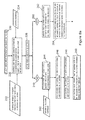
- a description of the operation of the ECS (26) according to the present invention will be done in relation to show the flow chart (30) in figures 5a to 5c .
- All blinds (22) are in their "open" position 32.
- a passenger from the aircraft requests a decrease in external light 34 via the IFE panel (21) in front of their seat (17).
- the IFE panel (21) sends a signal to the control unit (24) to indicate the request and the IFE panel (21) which made the request.
- the control unit (24) searches the zoning database at step 36 and determines which zones (27) contain the IFE panel which sent the request at step 38.
- the control unit (24) considers whether each zone (27) containing the IFE panel which sent the original request is already selected from the zoning database at step 40.
- the control unit (24) selects the corresponding matrix structures at step 44, from the matrix structure database at step 46.
- the control unit (24) duplicates the matrix structures (28) and creates an A matrix at step 46.
- the control unit updates the element (29) in the matrix structures (29), where the initial starting value for each element is zero, corresponding to the location of the IFE panel making the request, to a one at step 48.
- the control unit (24) the duplicates the matrix structures (28) again and creates a Z matrix at step 50.
- the Z matrix is a weighting matrix.
- the control unit (24) updates the values of the elements within the Z matrix, where elements corresponding to IFE panels located close to the blind are assigned higher values, for instance six, than elements corresponding to IFE panels (21) located further away from the blind, for instance zero.
- the control unit (24) then starts a timer on the clock at step 52 so that the control unit (24) can monitor the A and Z matrices for, a predetermined period of time, in this example ten minutes, at step 54.
- control unit (24) If after the first request was received by the control unit (24), no other requests were received from an IFE panel (21) within the same zone within the predetermined period of time (ten minutes), the control unit (24) sends a signal to the FAP (20) with details of the IFE panel (21) sending the original request so that the flight crew can address the needs of that passenger at step 56.
- the A and Z matrices are then erased 58 at step.
- the control unit (24) searches the zoning database at step 36 to determine which zones (27) contain the IFE panel (21) sending the request 38 at step. If the zone (27) is currently selected at step 60, then the control unit (24) finds the corresponding A matrix and updates the element within the A matrix, corresponding to location of the IFE panel (21), with a one at step 62. The control unit (24) then instructs the control unit (24) to send a signal to all IFE panels (21) within the zone at step 64 to display a message on the display unit asking whether the passenger would like to decrease the external light at step 66.
- the control unit (24) triggers a timer for a predetermined period of time for instance ten minutes at step 68. Passengers input “YES” or “NO” via the input device on their IFE panels (21) at step 70.
- the processor converts this input to a signal to be sent to the control unit (24).
- the processor processes any signals received in response to the poll.
- the control unit (24) calculates the survey answer ratio, ⁇ , at step 76 by dividing A' matrix by the number of elements (29) within A' Matrix. Matrix A' is then divided by the number of elements within the A' matrix to give the answer ratio, ⁇ , at step 76.
- the control unit (24) searches a look up table, within the memory unit, to find the threshold value ⁇ , for example 0.3, for the selected zone at step 78. ⁇ is then compared to ⁇ at step 80.
- control unit (24) sends a signal to the IFE panels (21) in the zone (27) to display a message on the display unit advising that the status of the blind will not be closed due to a majority decision 84 at step.
- the A and Z matrices are then erased and a timer is started 86 at step for a predetermined period of time, in this example twenty minutes, then the zone and the matrix structure are deselected 88.
- control unit sends a signal to operate the actuator (23) of the corresponding blind to move it from an "open" position to a "closed” position at step 92.
- the A and Z matrices are then erased and a timer is started 86 at step for a predetermined period of time, in this example twenty minutes, then the zone and the matrix structure are deselected 88.
- control unit (24) allows a zone of passengers to collaboratively control a blind.
- the weighting "Z" matrix also provides priority for the passengers whose seats (17) are closest to the blind within a zone (27).
- the function of the Z matrix is to assign a weighting to each IFE panel according to their localities to the environmental device (22).
- control unit (24) which can be modified to allow passengers to "open” the blind rather than just “close” the blind.
- an override function is added to the ECS (26).
- the override function is in the form of a switch located in the proximity of each window.
- a signal is sent to the control unit (24) which searches the zoning database for the zone (27) containing the blind closest to where the switch is located.
- the zone (27) in the memory unit is then locked by the control unit (24).
- a timer is started and for (20) minutes, for instance, the control unit cannot select the zone (27) from the zoning database.
- This variant provides for priority passengers closest to the blind, cabin, or flight crew, to have full control over the position of the blind regardless of the wishes of the other passengers within the zone (27). This can help during landing for example when all blinds (22) should be in the "open" position.
- the ECS (24) can determine the position of a blind by sending an interrogation signal to the actuator (23) which sends a response signal back to the control unit (24) detailing its current position.
- the control unit (24) assesses if the request for a change of position in the blind, requested by the IFE panel, is possible. If it is possible to change the position of the blind, the control unit (24) continues with the aforementioned method of operation. If a change of position of the blind is not possible, the control unit (24) sends a signal to the IFE panel to display a message to the passenger on the electronic display unit that the change of external light request is not possible.
- the windows are replaced by conventional electrochromic windows which form environmental devices (122).
- the electrochromic windows are each linked to a power supply (123).
- the method of operating the ECS 27, as shown in figure 5c is similar to the one described above with the difference that the control unit (24) sends a signal to the power supply (123).
- the power supply (123) After receiving the signal from the control unit (24), the power supply (123) applies a voltage across the electrochromic window to change its opacity from transparent "open” to opaque "closed".
- the power supply (123) removes the voltage applied to the electrochromic window and the opacity of the electrochromic window remains opaque "closed” as it is well known. It is possible then to modify the method of operating the ECS (26) so that the electrochromic window changes from opaque "closed” to transparent “open”. In order to achieve this change, the voltage applied to the power supply (123) is reversed.
- the environmental system (222) is an air conditioning system.
- the air conditioning system comprises an air supplying device (223), air supply ducts (224) and inlets (225).
- the air supplying device which is not shown in detail in the figures, is linked to the control unit (24).
- the air supplying device comprises a compressor, which is fed with high temperature bleed air from an aircraft engine, and a mixer.
- the mixer is also fed by a duct supplying ram air at the temperature and pressure outside the fuselage of the aircraft (10), and re-circulated air from within the passenger section (13) of the cabin.
- Valves and temperature sensors are located at the mixer's interface with the compressor, re-circulated air, ram air, and air supply ducts (224) located downstream of the mixer to regulate the temperature and pressure at the outlet of the mixer.
- the air supply duct (224) enters the passenger section (13) and expels air at the requested temperature via inlets (225).
- the cabin crew input a temperature range to the control unit (24) via the FAP at step 230.
- a passenger inputs a change of temperature request via their IFE panel at step 232.
- the control unit (24) searches the zoning database at step 234 and selects the zones which contain the IFE panel which made the request 236.
- the control unit (24) determines if a zone is already selected at step 238. If a zone (27) isn't already selected 240, the control unit (24) searches the matrix structure database at step 242 and selects the matrix structure (28) corresponding to that zone at step 244.
- the control unit then duplicates the matrix structure and creates an A 246 and a B matrix at step 248.
- the control unit updates the element corresponding to the IFE panel making the request, with a one at step 240.
- a timer is started at step 242. If no temperature change requests received by the ECS (26) within ten minutes at step 244 the control unit (24) sends a message to the FAP so that the flight crew can attend to the needs of the passenger who made the temperature change request at step 246.
- the A matrix is then delete and the zone deselected at step 248.
- control unit (24) searches the zoning database at step 234 and selects the zones containing the IFE panel making the request at step 236.
- the control unit compares the zone to those already selected at step 238. If a zone is already selected at step 260 updates the element in the A matrix corresponding to the location of the IFE panel making the request with a one at step 262.
- the control unit (24) then sends a signal to the IFE panels within the zone to display a poll on the electronic display asking if the passengers want to change the temperature within the zone at step 264.
- the control unit starts a timer at step 266.
- the control unit updates the elements of the B matrix with a one for an increase in temperature, a decrease in temperature, and already satisfied responses at step 270.
- the control unit (24) updates the elements of the B matrix with a one for an increase in temperature request and a minus one for a decrease in temperature request, whereas the already satisfied responses remain as zero at step 272.
- the control unit searches a look up table within the memory unit at step 276 and compares a threshold value ⁇ from the look up table to the survey answer ratio, ⁇ , at step 278.
- control unit sends a signal to the IFE panels within the zone to display a message on the electronic display explaining to the passengers that temperature is not seen as a problem at step 282.
- the control unit then erases matrices A and B for that zone Ind starts a timer at step 284.
- the control unit (24) then deselects the zone (27)and cannot reselect it for twenty minutes.
- the control unit (24) searches a look up table within the memory unit which contains a set of temperature values for a range of ⁇ values at step 290.
- the control unit selects a temperature value corresponding to the ⁇ that has been calculated at step 292.
- the control unit compares the temperature value against the temperature limits at step 294. If the temperature change is allowed at step 296, the control unit sends a signal with a temperature setting to the air supplying device at step 298.
- the air supplying device configures the valves interfacing between the mixer and the compressor, the ram air duct, the re-circulating air duct and the air supply duct (223) to deliver the correct air temperature to the passenger section (13) via the inlets (224) in the affected zone (27).
- the control unit then erases matrices A and B for that zone and starts a timer at step 284.
- the control unit (24) deselects the zone (27) and cannot reselect it for twenty minutes at step 286.
- the control unit sends a signal to the FAP to display a message on the electronic display advising the cabin-crew that a zone of passengers is requesting a temperature outside of the temperature limits at step 302 so the cabin crew can deal with the situation by either resetting the temperature range or treating the passengers in the zone.
- the control unit then erases matrices A and B for that zone and starts a timer at step 284.
- the control unit (24) then deselects the zone (27) and cannot reselect it for twenty minutes at step 286.
- the environmental device is a mood lighting system.
- the mood lighting system is used in conjunction with the air supplying devices.
- the mood lighting system comprises at least three LEDs; one yellow, one blue, and one red, and a diffuser.
- the control unit sends a signal to configure the diffuser to allow a higher percentage of red light through.
- the control unit sends a signal to configure the diffuser to allow a higher percentage of blue light through.
- the increase in blue or red light passing through the diffuser is known as a change in colour temperature. A change in colour temperature is gives the passengers in the zone the artificial feeling that the physical temperature has changed.
- the ECS (26) is by no means limited to the aforementioned variants. It will be well appreciated by one skilled in the art that a similar method of operating the ECS (26) can be applied for other environmental devices such as volume control for a speaker system. It will be appreciated that the user interface panels (20) can be personal devices such as laptops, tablet computers, smart phones, or the like. Also, the ECS can be transferred to vehicles other than an aircraft, such as a coach.
Landscapes
- Engineering & Computer Science (AREA)
- Aviation & Aerospace Engineering (AREA)
- Air-Conditioning For Vehicles (AREA)
Abstract
Description
- The present invention relates to an environmental control system for controlling environmental devices integrated onto a vehicle, for example, an air conditioning system, a window shading system, or a mood lighting system and the like or any combination of such systems. The environmental control system is particularly suitable for use in commercial aircraft.
- According to the first aspect of the invention there is provided an environmental control system (ECS) integrated into a vehicle, comprising at least one environmental device and a plurality of user interface devices linked to a control unit, characterised in that the control unit operates the at least one environmental device depending on majority of inputs received from the plurality of user interface devices, in such a way that, in-use, the collaborative wishes of users controls the device.
- According to a second aspect of the invention there is provided a method of operating an environment control system, the environment control system operating at least one environmental device, comprising the steps of:
- a. monitoring change requests sent by a plurality of user interface devices
- b. Triggering a poll survey amongst a plurality of user interface devices and monitoring responses to the poll for a predetermined time period
- c. Receiving responses to the poll sent by inputs on the user interface devices
- d. Synthesizing the responses to the poll into a single entity
- e. Depending on the single entity, sending a signal to operate the environmental device.
- According to a further aspect of the invention there is provided an aircraft comprising a fuselage having a cabin divided into at least a passenger section, a plurality of user interface devices arranged in the passenger section connected to an environment control system according to the first aspect of the invention.
- The invention will now be described by way of example with reference to the accompanying drawings, of which:-
-
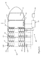
Figure 1 shows a schematic view of a longitudinal section of a forward portion of a cabin of an aircraft fuselage including an Environment Control System (ECS) according to the present invention; -
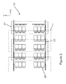
Figure 2 is a similar view asfigure 1 showing the forward portion of the cabin divided into a plurality of zones by the ECS; -
Figure 3 shows zone I fromfigure 2 comprising one environment device and an arrangement of user interface devices; -
Figure 4 shows a matrix structure arranged to represent the arrangement of user interface devices as shown inFigure 3 ; -
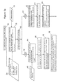
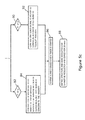
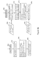
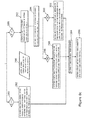
Figures 5a to 5c show a flow chart detailing a method of operating the ECS according to the present invention; -
Figure 6 is a similar view asfigure 1 showing the ECS according to a variant of the present invention linked to a plurality of electrochromic windows; -
Figure 7 is a similar view asfigure 1 showing the ECS according to another variant of the present invention linked to a plurality of air supply devices; and -
Figures 8a to 8c show flow charts detailing a method of operating the ECS as shown infigure 7 . - With reference to
figure 1 , there is shown an aircraft fuselage (10), comprising a longitudinal (X) and a transversal (Y) axis, having a cockpit (11) and a cabin (12), which is divided into a passenger section (13) and a cabin-crew section (14). The cockpit (11) is separated from the cabin by a partition (15). The cabin comprises a divider (16) for separating the cabin-crew section (14) from the passenger section (13). Seats (17), having a seat back (18) and a seat base (19), are arranged in rows in the passenger section (13). Each row comprises six seats (17) in line transversally (Y) with each other. In the passenger section (13), there is a plurality of user interface devices (20) called In-Flight Entertainment (IFE) panels. The user interface device (20) is preferably a touch screen panel comprising the input unit, processor unit, and electronic display unit hence forming a single device. There is another user interface device (21) in the cabin crew section called Flight Attendant Panel (FAP). The user interface device (21) comprises an input unit for sending electronic signals to a processor unit. The processor unit is connected to an electronic display unit. The IFE panels (21) are located in front of each seat (17) integrated into the seat back (18) of the seat in front or embedded into the divider (16) in front of the seat. In a conventional manner, a plurality of windows are installed in the fuselage (10). An environmental device (22) having the form of a motorised blind is arranged onto each window. Each blind is connected to an actuator (23) for operating the blind between a retracted, or "open", position and a position covering the window, or "closed" position. - A control unit (24) is linked to the IFE panels (20) and the FAP (21) respectively, an input device (25), and the actuators (23) altogether forming an environment control system (ECS) (26) The control unit (24) allows electronic signals to be sent to and received from, the IFE panels (20) and the FAP (21). The control unit (24) is capable of sending electronic signals to each motor for controlling the power output settings. The input device (25) is preferably a CD ROM drive but may also be a USB port, an electronic tape reader or the like.
- The control unit (24) comprises a processor, a memory unit, and a clock capable of running a plurality of timers in parallel. A zone (27) is created for each blind, as shown in
figure 2 , and saved to a zoning database created in the memory unit of the control unit (24). A matrix structure database is created within the memory of the control unit (24). With reference tofigure 4 , for each zone, a matrix structure (28) is created within the matrix structure database. Each matrix structure comprises a plurality of elements (29). In this example the matrix is made of an arrangement of 6x3 elements corresponding to the IFE panels (21) of the corresponding zone (27) - A description of the operation of the ECS (26) according to the present invention will be done in relation to show the flow chart (30) in
figures 5a to 5c . All blinds (22) are in their "open"position 32. A passenger from the aircraft requests a decrease inexternal light 34 via the IFE panel (21) in front of their seat (17). The IFE panel (21) sends a signal to the control unit (24) to indicate the request and the IFE panel (21) which made the request. The control unit (24) searches the zoning database at step 36 and determines which zones (27) contain the IFE panel which sent the request atstep 38. The control unit (24) considers whether each zone (27) containing the IFE panel which sent the original request is already selected from the zoning database atstep 40. If any of the zones (27) have not already been selected at step 42, the control unit (24) selects the corresponding matrix structures atstep 44, from the matrix structure database atstep 46. The control unit (24) duplicates the matrix structures (28) and creates an A matrix atstep 46. The control unit updates the element (29) in the matrix structures (29), where the initial starting value for each element is zero, corresponding to the location of the IFE panel making the request, to a one atstep 48. The control unit (24) the duplicates the matrix structures (28) again and creates a Z matrix atstep 50. The Z matrix is a weighting matrix. The control unit (24) updates the values of the elements within the Z matrix, where elements corresponding to IFE panels located close to the blind are assigned higher values, for instance six, than elements corresponding to IFE panels (21) located further away from the blind, for instance zero. The control unit (24) then starts a timer on the clock atstep 52 so that the control unit (24) can monitor the A and Z matrices for, a predetermined period of time, in this example ten minutes, atstep 54. - If after the first request was received by the control unit (24), no other requests were received from an IFE panel (21) within the same zone within the predetermined period of time (ten minutes), the control unit (24) sends a signal to the FAP (20) with details of the IFE panel (21) sending the original request so that the flight crew can address the needs of that passenger at
step 56. The A and Z matrices are then erased 58 at step. - If another request is made by a passenger via their IFE panel (21) for a reduction in
external light 34, the control unit (24) searches the zoning database at step 36 to determine which zones (27) contain the IFE panel (21) sending therequest 38 at step. If the zone (27) is currently selected atstep 60, then the control unit (24) finds the corresponding A matrix and updates the element within the A matrix, corresponding to location of the IFE panel (21), with a one atstep 62. The control unit (24) then instructs the control unit (24) to send a signal to all IFE panels (21) within the zone atstep 64 to display a message on the display unit asking whether the passenger would like to decrease the external light atstep 66. The control unit (24) triggers a timer for a predetermined period of time for instance ten minutes atstep 68. Passengers input "YES" or "NO" via the input device on their IFE panels (21) atstep 70. The processor converts this input to a signal to be sent to the control unit (24). The processor processes any signals received in response to the poll. The elements (29) in the A matrix, corresponding to the location of IFE panels sending the signals, are updated with a value = 1 for "YES" and value = 0 for "NO" atstep 72. When the timer reaches the predetermined period, i.e. ten minutes, the control unit (24) calculates an A' matrix where A' = A*Z 74. Note that the A' matrix will have the same size, e.g. 6 x 3 matrix, as the A and Z matrices. Then the control unit (24) calculates the survey answer ratio, η, atstep 76 by dividing A' matrix by the number of elements (29) within A' Matrix. Matrix A' is then divided by the number of elements within the A' matrix to give the answer ratio, η, atstep 76. The control unit (24) then searches a look up table, within the memory unit, to find the threshold value µ, for example 0.3, for the selected zone atstep 78. η is then compared to µ atstep 80. - If η is less than
µ 82, the control unit (24) sends a signal to the IFE panels (21) in the zone (27) to display a message on the display unit advising that the status of the blind will not be closed due to amajority decision 84 at step. The A and Z matrices are then erased and a timer is started 86 at step for a predetermined period of time, in this example twenty minutes, then the zone and the matrix structure are deselected 88. - If η is greater than
µ 90, the control unit sends a signal to operate the actuator (23) of the corresponding blind to move it from an "open" position to a "closed" position atstep 92. The A and Z matrices are then erased and a timer is started 86 at step for a predetermined period of time, in this example twenty minutes, then the zone and the matrix structure are deselected 88. - One of the advantages associated with this
ECS 27, according to the invention, is that the control unit (24) allows a zone of passengers to collaboratively control a blind. The weighting "Z" matrix also provides priority for the passengers whose seats (17) are closest to the blind within a zone (27). - It will be appreciated that the numerical values within the Z matrices can cover a large range. The function of the Z matrix is to assign a weighting to each IFE panel according to their localities to the environmental device (22).
- In a variant of the invention not shown, the control unit (24) which can be modified to allow passengers to "open" the blind rather than just "close" the blind.
- In a further variant not shown, an override function is added to the ECS (26). The override function is in the form of a switch located in the proximity of each window. When the switch is pressed, a signal is sent to the control unit (24) which searches the zoning database for the zone (27) containing the blind closest to where the switch is located. The zone (27) in the memory unit is then locked by the control unit (24). A timer is started and for (20) minutes, for instance, the control unit cannot select the zone (27) from the zoning database. This variant provides for priority passengers closest to the blind, cabin, or flight crew, to have full control over the position of the blind regardless of the wishes of the other passengers within the zone (27). This can help during landing for example when all blinds (22) should be in the "open" position.
- In a further variant, the ECS (24) can determine the position of a blind by sending an interrogation signal to the actuator (23) which sends a response signal back to the control unit (24) detailing its current position. When the control unit (24) receives the response signal from the actuator (23), the control unit (24) assesses if the request for a change of position in the blind, requested by the IFE panel, is possible. If it is possible to change the position of the blind, the control unit (24) continues with the aforementioned method of operation. If a change of position of the blind is not possible, the control unit (24) sends a signal to the IFE panel to display a message to the passenger on the electronic display unit that the change of external light request is not possible.
- In another variant, as shown in
figure 6 , the windows are replaced by conventional electrochromic windows which form environmental devices (122). In this embodiment, the electrochromic windows are each linked to a power supply (123). The power supplies (123) linked to the control unit (24). - The method of operating the
ECS 27, as shown infigure 5c , is similar to the one described above with the difference that the control unit (24) sends a signal to the power supply (123). After receiving the signal from the control unit (24), the power supply (123) applies a voltage across the electrochromic window to change its opacity from transparent "open" to opaque "closed". When the opacity has changed, the power supply (123) removes the voltage applied to the electrochromic window and the opacity of the electrochromic window remains opaque "closed" as it is well known. It is possible then to modify the method of operating the ECS (26) so that the electrochromic window changes from opaque "closed" to transparent "open". In order to achieve this change, the voltage applied to the power supply (123) is reversed. - With reference to
figure 7 , in a further embodiment, the environmental system (222) is an air conditioning system. The air conditioning system comprises an air supplying device (223), air supply ducts (224) and inlets (225). The air supplying device, which is not shown in detail in the figures, is linked to the control unit (24). The air supplying device comprises a compressor, which is fed with high temperature bleed air from an aircraft engine, and a mixer. The mixer is also fed by a duct supplying ram air at the temperature and pressure outside the fuselage of the aircraft (10), and re-circulated air from within the passenger section (13) of the cabin. Valves and temperature sensors (also not shown in the figures) are located at the mixer's interface with the compressor, re-circulated air, ram air, and air supply ducts (224) located downstream of the mixer to regulate the temperature and pressure at the outlet of the mixer. The air supply duct (224) enters the passenger section (13) and expels air at the requested temperature via inlets (225). - The method of operating the ECS (26) for this variant is described now with reference to
figures 8a to 8c . The cabin crew input a temperature range to the control unit (24) via the FAP atstep 230. A passenger inputs a change of temperature request via their IFE panel atstep 232. The control unit (24) searches the zoning database atstep 234 and selects the zones which contain the IFE panel which made therequest 236. The control unit (24) determines if a zone is already selected atstep 238. If a zone (27) isn't already selected 240, the control unit (24) searches the matrix structure database atstep 242 and selects the matrix structure (28) corresponding to that zone atstep 244. The control unit then duplicates the matrix structure and creates anA 246 and a B matrix atstep 248. The control unit updates the element corresponding to the IFE panel making the request, with a one atstep 240. A timer is started atstep 242. If no temperature change requests received by the ECS (26) within ten minutes atstep 244 the control unit (24) sends a message to the FAP so that the flight crew can attend to the needs of the passenger who made the temperature change request atstep 246. The A matrix is then delete and the zone deselected atstep 248. - If another request is made for a change in temperature at
step 232 the control unit (24) searches the zoning database atstep 234 and selects the zones containing the IFE panel making the request atstep 236. The control unit compares the zone to those already selected atstep 238. If a zone is already selected atstep 260 updates the element in the A matrix corresponding to the location of the IFE panel making the request with a one atstep 262. The control unit (24) then sends a signal to the IFE panels within the zone to display a poll on the electronic display asking if the passengers want to change the temperature within the zone atstep 264. The control unit starts a timer atstep 266. Passengers input if they would like an increase in temperature, a decrease in temperature, or whether they are satisfied via their IFE panel atstep 268. The control unit updates the elements of the B matrix with a one for an increase in temperature, a decrease in temperature, and already satisfied responses atstep 270. The control unit (24) updates the elements of the B matrix with a one for an increase in temperature request and a minus one for a decrease in temperature request, whereas the already satisfied responses remain as zero atstep 272. At a time of ten minutes, the control unit calculates a survey answer ratio η=sum(B)/n where n is the number of elements within the B matrix and the sum operation adds up the numerical values of the elements within the B matrix. The control unit also calculates a temperature input θ=sum(A)/sum(B). The control unit searches a look up table within the memory unit atstep 276 and compares a threshold value µ from the look up table to the survey answer ratio, η, atstep 278. - If η is less than
µ 280 the control unit sends a signal to the IFE panels within the zone to display a message on the electronic display explaining to the passengers that temperature is not seen as a problem atstep 282. The control unit then erases matrices A and B for that zone Ind starts a timer atstep 284. The control unit (24) then deselects the zone (27)and cannot reselect it for twenty minutes. - If η is greater than
µ 288, the control unit (24) searches a look up table within the memory unit which contains a set of temperature values for a range of θ values atstep 290. The control unit selects a temperature value corresponding to the θ that has been calculated atstep 292. The control unit then compares the temperature value against the temperature limits atstep 294. If the temperature change is allowed atstep 296, the control unit sends a signal with a temperature setting to the air supplying device atstep 298. The air supplying device configures the valves interfacing between the mixer and the compressor, the ram air duct, the re-circulating air duct and the air supply duct (223) to deliver the correct air temperature to the passenger section (13) via the inlets (224) in the affected zone (27). The control unit then erases matrices A and B for that zone and starts a timer atstep 284. The control unit (24) then deselects the zone (27) and cannot reselect it for twenty minutes atstep 286. - If the temperature value falls outside of the temperature limits at
step 300, the control unit sends a signal to the FAP to display a message on the electronic display advising the cabin-crew that a zone of passengers is requesting a temperature outside of the temperature limits atstep 302 so the cabin crew can deal with the situation by either resetting the temperature range or treating the passengers in the zone. The control unit then erases matrices A and B for that zone and starts a timer atstep 284. The control unit (24) then deselects the zone (27) and cannot reselect it for twenty minutes atstep 286. - In a further variant, the environmental device is a mood lighting system. Preferably the mood lighting system is used in conjunction with the air supplying devices. There is one mood lighting system in each zone defined by the ECS (26) for the air conditioning system (222). The mood lighting system comprises at least three LEDs; one yellow, one blue, and one red, and a diffuser. During operation, if the temperature value is above the temperature limits set by the cabin crew at
step 302, the control unit sends a signal to configure the diffuser to allow a higher percentage of red light through. If the temperature value is lower than the temperature limits set by the cabin crew atstep 302, the control unit (24) sends a signal to configure the diffuser to allow a higher percentage of blue light through. The increase in blue or red light passing through the diffuser is known as a change in colour temperature. A change in colour temperature is gives the passengers in the zone the artificial feeling that the physical temperature has changed. - The ECS (26) is by no means limited to the aforementioned variants. It will be well appreciated by one skilled in the art that a similar method of operating the ECS (26) can be applied for other environmental devices such as volume control for a speaker system. It will be appreciated that the user interface panels (20) can be personal devices such as laptops, tablet computers, smart phones, or the like. Also, the ECS can be transferred to vehicles other than an aircraft, such as a coach.
Claims (11)
- An environmental control system (ECS) (26) integrated into a vehicle, comprising at least one environmental device (22); (122); (222) and a plurality of user interface devices (20),(21) linked to a control unit (24), characterised in that the control unit (24) operates the at least one environmental device (22); (122); (222) depending on majority of inputs received from the plurality of user interface devices (20),(21), in such a way that, in-use, the collaborative wishes of users controls the device (22); (122); (222).
- The system (26) according to claim 1, wherein the vehicle comprises a plurality of windows and in that the environmental device 22 is a motorised blind arranged near each window, the blind being moveable and operated between an "open" position and a "closed" position by the control unit (24).
- The system (27) according to claim 1 wherein the environmental device (122) is an electrochromic window.
- The system (27) according to claim 3 wherein the control unit (24) is linked to a power supply (123) so as to apply a voltage across the electrochromic window for changing its opacity
- The system (27) according to claim 1 wherein the environmental device (222) is an air conditioning system
- The system (26) according to claim 1 wherein at least one environmental device (22; 122; 222) is a mood lighting system.
- The system (26) according to claim 1 further comprising a switch for operating the environmental device (22; 122; 222)
- A method of operating an environment control system (26) as claimed in claims 1 to 7, the environment control system operating at least one environmental device (22; 122; 222), comprising the steps of:a. monitoring change requests sent by a plurality of user interface devices (20, 21)b. Triggering a poll survey amongst a plurality of user interface devices (20) and monitoring responses to the poll for a predetermined time periodc. Receiving responses to the poll sent by inputs on the user interface devices (20)d. Synthesizing the responses to the poll into a single entitye. Depending on the single entity, sending a signal to operate the environmental device (22); (122); (222).
- The method as claimed in claim 8, further comprising after step d) the step d') of, selecting a threshold value from a look-up table and comparing the single entity against the threshold value,
- The method as claimed in claim 9 wherein step e) further comprises if the single entity is greater than the threshold value sending a signal to operate the environmental device (22); (122); (222) and if the single entity is less than the threshold value, sending A message to the plurality of user interface devices (20) informing that the environmental device (22; 122; 222) will not be operated.
- An aircraft comprising a fuselage (10) having a cabin (12) divided into at least a passenger section (13), a plurality of user interface devices (20) arranged in the passenger section (13) connected to an environment control system (26) as claimed in claims 1 to 7, the fuselage further comprising at least one environmental device (22; 122; 222) operated by the environmental control system (26).
Priority Applications (1)
| Application Number | Priority Date | Filing Date | Title |
|---|---|---|---|
| EP12163449.7A EP2647570B1 (en) | 2012-04-05 | 2012-04-05 | Environment control system |
Applications Claiming Priority (1)
| Application Number | Priority Date | Filing Date | Title |
|---|---|---|---|
| EP12163449.7A EP2647570B1 (en) | 2012-04-05 | 2012-04-05 | Environment control system |
Publications (2)
| Publication Number | Publication Date |
|---|---|
| EP2647570A1 true EP2647570A1 (en) | 2013-10-09 |
| EP2647570B1 EP2647570B1 (en) | 2014-03-12 |
Family
ID=46049180
Family Applications (1)
| Application Number | Title | Priority Date | Filing Date |
|---|---|---|---|
| EP12163449.7A Active EP2647570B1 (en) | 2012-04-05 | 2012-04-05 | Environment control system |
Country Status (1)
| Country | Link |
|---|---|
| EP (1) | EP2647570B1 (en) |
Cited By (2)
| Publication number | Priority date | Publication date | Assignee | Title |
|---|---|---|---|---|
| DE102013101354A1 (en) * | 2013-02-12 | 2014-08-14 | Airbus Operations Gmbh | Airplane has compressor whose inlet is connected to fresh air source and outlet is connected with air conditioning unit whose outlet is connected with air distributor of respective associated zone |
| EP4015388A1 (en) * | 2020-12-21 | 2022-06-22 | Collins Aerospace Ireland, Limited | Aircraft cabin air management system |
Citations (3)
| Publication number | Priority date | Publication date | Assignee | Title |
|---|---|---|---|---|
| US20050200937A1 (en) * | 2004-03-12 | 2005-09-15 | The Boeing Company | Multi-color electrochromic apparatus and methods |
| DE102006005523A1 (en) * | 2006-02-07 | 2007-08-16 | Airbus Deutschland Gmbh | Window unit e.g. for aircraft with shading and lighting functions |
| US20080234893A1 (en) * | 2007-03-23 | 2008-09-25 | The Boeing Company | Window control system |
-
2012
- 2012-04-05 EP EP12163449.7A patent/EP2647570B1/en active Active
Patent Citations (3)
| Publication number | Priority date | Publication date | Assignee | Title |
|---|---|---|---|---|
| US20050200937A1 (en) * | 2004-03-12 | 2005-09-15 | The Boeing Company | Multi-color electrochromic apparatus and methods |
| DE102006005523A1 (en) * | 2006-02-07 | 2007-08-16 | Airbus Deutschland Gmbh | Window unit e.g. for aircraft with shading and lighting functions |
| US20080234893A1 (en) * | 2007-03-23 | 2008-09-25 | The Boeing Company | Window control system |
Cited By (2)
| Publication number | Priority date | Publication date | Assignee | Title |
|---|---|---|---|---|
| DE102013101354A1 (en) * | 2013-02-12 | 2014-08-14 | Airbus Operations Gmbh | Airplane has compressor whose inlet is connected to fresh air source and outlet is connected with air conditioning unit whose outlet is connected with air distributor of respective associated zone |
| EP4015388A1 (en) * | 2020-12-21 | 2022-06-22 | Collins Aerospace Ireland, Limited | Aircraft cabin air management system |
Also Published As
| Publication number | Publication date |
|---|---|
| EP2647570B1 (en) | 2014-03-12 |
Similar Documents
| Publication | Publication Date | Title |
|---|---|---|
| EP3470327B1 (en) | Interactive dimmable window systems and methods | |
| EP3201089B1 (en) | Smart passenger service unit | |
| DE102008017051B4 (en) | Method for controlling an air conditioning system of a vehicle and operating device for an air conditioning system | |
| US20190141447A1 (en) | Smart Passenger Service Unit | |
| US20160062618A1 (en) | System and method of operation of the system incorporating a graphical user interface in a side ledge of a vehicle cabin | |
| US9650141B2 (en) | System and a method of operation of the system incorporating a graphical user interface in a bulkhead of a vehicle cabin | |
| US20100187354A1 (en) | Information system for messages from passengers to the cabin crew | |
| US20170291469A1 (en) | Electronic ventilation register control system for a motor vehicle | |
| CN108431762B (en) | System and method for controlling functions in a vehicle cabin | |
| EP3578462B1 (en) | Artificially intelligent flight crew systems and methods | |
| EP3243751B1 (en) | Tuned aircraft lighting for an improved flight experience | |
| EP3075658B1 (en) | Ram air system and methods of manufacturing the same | |
| US9290118B2 (en) | Heated flight attendant jumpseats for commercial airplane applications | |
| US20250353612A1 (en) | Methods and systems for lighting a vertical take-off and landing vehicle | |
| EP2647570B1 (en) | Environment control system | |
| DE102018205690A1 (en) | Method and system for controlling a user interface and an air conditioning unit | |
| AU2014274529A1 (en) | Control module unit for services systems for a vehicle | |
| US10668786B2 (en) | HVAC register recall position system | |
| WO2020208420A1 (en) | Air gasper with integrated fan | |
| US10279890B2 (en) | Configurable control panel for an aircraft cockpit and method of configuration for such a panel | |
| US11029574B2 (en) | Wirelessly controlled electrically switchable window system | |
| WO2017089861A1 (en) | System and a method of operation of the system incorporating a graphical user interface on a mobile computing device for a passenger in a vehicle cabin | |
| EP4446222A1 (en) | Controller feedback system and method | |
| US11024285B2 (en) | Noise-reduction in aircraft | |
| US9260188B1 (en) | Apparatus and method for allowing multi-mode use of an aircraft cockpit |
Legal Events
| Date | Code | Title | Description |
|---|---|---|---|
| PUAI | Public reference made under article 153(3) epc to a published international application that has entered the european phase |
Free format text: ORIGINAL CODE: 0009012 |
|
| 17P | Request for examination filed |
Effective date: 20120405 |
|
| AK | Designated contracting states |
Kind code of ref document: A1 Designated state(s): AL AT BE BG CH CY CZ DE DK EE ES FI FR GB GR HR HU IE IS IT LI LT LU LV MC MK MT NL NO PL PT RO RS SE SI SK SM TR |
|
| AX | Request for extension of the european patent |
Extension state: BA ME |
|
| GRAP | Despatch of communication of intention to grant a patent |
Free format text: ORIGINAL CODE: EPIDOSNIGR1 |
|
| RIC1 | Information provided on ipc code assigned before grant |
Ipc: B64D 11/00 20060101AFI20131113BHEP Ipc: B64D 13/06 20060101ALI20131113BHEP |
|
| INTG | Intention to grant announced |
Effective date: 20131213 |
|
| GRAS | Grant fee paid |
Free format text: ORIGINAL CODE: EPIDOSNIGR3 |
|
| GRAA | (expected) grant |
Free format text: ORIGINAL CODE: 0009210 |
|
| AK | Designated contracting states |
Kind code of ref document: B1 Designated state(s): AL AT BE BG CH CY CZ DE DK EE ES FI FR GB GR HR HU IE IS IT LI LT LU LV MC MK MT NL NO PL PT RO RS SE SI SK SM TR |
|
| REG | Reference to a national code |
Ref country code: GB Ref legal event code: FG4D |
|
| REG | Reference to a national code |
Ref country code: CH Ref legal event code: EP |
|
| REG | Reference to a national code |
Ref country code: AT Ref legal event code: REF Ref document number: 656107 Country of ref document: AT Kind code of ref document: T Effective date: 20140315 |
|
| REG | Reference to a national code |
Ref country code: IE Ref legal event code: FG4D |
|
| REG | Reference to a national code |
Ref country code: DE Ref legal event code: R096 Ref document number: 602012000983 Country of ref document: DE Effective date: 20140424 |
|
| REG | Reference to a national code |
Ref country code: NL Ref legal event code: VDEP Effective date: 20140312 |
|
| PG25 | Lapsed in a contracting state [announced via postgrant information from national office to epo] |
Ref country code: LT Free format text: LAPSE BECAUSE OF FAILURE TO SUBMIT A TRANSLATION OF THE DESCRIPTION OR TO PAY THE FEE WITHIN THE PRESCRIBED TIME-LIMIT Effective date: 20140312 Ref country code: NO Free format text: LAPSE BECAUSE OF FAILURE TO SUBMIT A TRANSLATION OF THE DESCRIPTION OR TO PAY THE FEE WITHIN THE PRESCRIBED TIME-LIMIT Effective date: 20140612 |
|
| REG | Reference to a national code |
Ref country code: AT Ref legal event code: MK05 Ref document number: 656107 Country of ref document: AT Kind code of ref document: T Effective date: 20140312 |
|
| REG | Reference to a national code |
Ref country code: LT Ref legal event code: MG4D |
|
| PG25 | Lapsed in a contracting state [announced via postgrant information from national office to epo] |
Ref country code: FI Free format text: LAPSE BECAUSE OF FAILURE TO SUBMIT A TRANSLATION OF THE DESCRIPTION OR TO PAY THE FEE WITHIN THE PRESCRIBED TIME-LIMIT Effective date: 20140312 Ref country code: CY Free format text: LAPSE BECAUSE OF FAILURE TO SUBMIT A TRANSLATION OF THE DESCRIPTION OR TO PAY THE FEE WITHIN THE PRESCRIBED TIME-LIMIT Effective date: 20140312 Ref country code: SE Free format text: LAPSE BECAUSE OF FAILURE TO SUBMIT A TRANSLATION OF THE DESCRIPTION OR TO PAY THE FEE WITHIN THE PRESCRIBED TIME-LIMIT Effective date: 20140312 |
|
| PG25 | Lapsed in a contracting state [announced via postgrant information from national office to epo] |
Ref country code: LV Free format text: LAPSE BECAUSE OF FAILURE TO SUBMIT A TRANSLATION OF THE DESCRIPTION OR TO PAY THE FEE WITHIN THE PRESCRIBED TIME-LIMIT Effective date: 20140312 Ref country code: RS Free format text: LAPSE BECAUSE OF FAILURE TO SUBMIT A TRANSLATION OF THE DESCRIPTION OR TO PAY THE FEE WITHIN THE PRESCRIBED TIME-LIMIT Effective date: 20140312 Ref country code: HR Free format text: LAPSE BECAUSE OF FAILURE TO SUBMIT A TRANSLATION OF THE DESCRIPTION OR TO PAY THE FEE WITHIN THE PRESCRIBED TIME-LIMIT Effective date: 20140312 |
|
| PG25 | Lapsed in a contracting state [announced via postgrant information from national office to epo] |
Ref country code: EE Free format text: LAPSE BECAUSE OF FAILURE TO SUBMIT A TRANSLATION OF THE DESCRIPTION OR TO PAY THE FEE WITHIN THE PRESCRIBED TIME-LIMIT Effective date: 20140312 Ref country code: NL Free format text: LAPSE BECAUSE OF FAILURE TO SUBMIT A TRANSLATION OF THE DESCRIPTION OR TO PAY THE FEE WITHIN THE PRESCRIBED TIME-LIMIT Effective date: 20140312 Ref country code: BE Free format text: LAPSE BECAUSE OF FAILURE TO SUBMIT A TRANSLATION OF THE DESCRIPTION OR TO PAY THE FEE WITHIN THE PRESCRIBED TIME-LIMIT Effective date: 20140312 Ref country code: RO Free format text: LAPSE BECAUSE OF FAILURE TO SUBMIT A TRANSLATION OF THE DESCRIPTION OR TO PAY THE FEE WITHIN THE PRESCRIBED TIME-LIMIT Effective date: 20140312 Ref country code: BG Free format text: LAPSE BECAUSE OF FAILURE TO SUBMIT A TRANSLATION OF THE DESCRIPTION OR TO PAY THE FEE WITHIN THE PRESCRIBED TIME-LIMIT Effective date: 20140612 Ref country code: CZ Free format text: LAPSE BECAUSE OF FAILURE TO SUBMIT A TRANSLATION OF THE DESCRIPTION OR TO PAY THE FEE WITHIN THE PRESCRIBED TIME-LIMIT Effective date: 20140312 Ref country code: IS Free format text: LAPSE BECAUSE OF FAILURE TO SUBMIT A TRANSLATION OF THE DESCRIPTION OR TO PAY THE FEE WITHIN THE PRESCRIBED TIME-LIMIT Effective date: 20140712 |
|
| PG25 | Lapsed in a contracting state [announced via postgrant information from national office to epo] |
Ref country code: PL Free format text: LAPSE BECAUSE OF FAILURE TO SUBMIT A TRANSLATION OF THE DESCRIPTION OR TO PAY THE FEE WITHIN THE PRESCRIBED TIME-LIMIT Effective date: 20140312 Ref country code: MC Free format text: LAPSE BECAUSE OF FAILURE TO SUBMIT A TRANSLATION OF THE DESCRIPTION OR TO PAY THE FEE WITHIN THE PRESCRIBED TIME-LIMIT Effective date: 20140312 Ref country code: ES Free format text: LAPSE BECAUSE OF FAILURE TO SUBMIT A TRANSLATION OF THE DESCRIPTION OR TO PAY THE FEE WITHIN THE PRESCRIBED TIME-LIMIT Effective date: 20140312 Ref country code: SK Free format text: LAPSE BECAUSE OF FAILURE TO SUBMIT A TRANSLATION OF THE DESCRIPTION OR TO PAY THE FEE WITHIN THE PRESCRIBED TIME-LIMIT Effective date: 20140312 Ref country code: AT Free format text: LAPSE BECAUSE OF FAILURE TO SUBMIT A TRANSLATION OF THE DESCRIPTION OR TO PAY THE FEE WITHIN THE PRESCRIBED TIME-LIMIT Effective date: 20140312 |
|
| REG | Reference to a national code |
Ref country code: DE Ref legal event code: R097 Ref document number: 602012000983 Country of ref document: DE |
|
| PG25 | Lapsed in a contracting state [announced via postgrant information from national office to epo] |
Ref country code: PT Free format text: LAPSE BECAUSE OF FAILURE TO SUBMIT A TRANSLATION OF THE DESCRIPTION OR TO PAY THE FEE WITHIN THE PRESCRIBED TIME-LIMIT Effective date: 20140714 |
|
| PLBE | No opposition filed within time limit |
Free format text: ORIGINAL CODE: 0009261 |
|
| STAA | Information on the status of an ep patent application or granted ep patent |
Free format text: STATUS: NO OPPOSITION FILED WITHIN TIME LIMIT |
|
| REG | Reference to a national code |
Ref country code: IE Ref legal event code: MM4A |
|
| PG25 | Lapsed in a contracting state [announced via postgrant information from national office to epo] |
Ref country code: DK Free format text: LAPSE BECAUSE OF FAILURE TO SUBMIT A TRANSLATION OF THE DESCRIPTION OR TO PAY THE FEE WITHIN THE PRESCRIBED TIME-LIMIT Effective date: 20140312 |
|
| 26N | No opposition filed |
Effective date: 20141215 |
|
| PG25 | Lapsed in a contracting state [announced via postgrant information from national office to epo] |
Ref country code: RS Free format text: LAPSE BECAUSE OF FAILURE TO SUBMIT A TRANSLATION OF THE DESCRIPTION OR TO PAY THE FEE WITHIN THE PRESCRIBED TIME-LIMIT Effective date: 20140903 |
|
| REG | Reference to a national code |
Ref country code: DE Ref legal event code: R097 Ref document number: 602012000983 Country of ref document: DE Effective date: 20141215 |
|
| PG25 | Lapsed in a contracting state [announced via postgrant information from national office to epo] |
Ref country code: IT Free format text: LAPSE BECAUSE OF FAILURE TO SUBMIT A TRANSLATION OF THE DESCRIPTION OR TO PAY THE FEE WITHIN THE PRESCRIBED TIME-LIMIT Effective date: 20140312 |
|
| PG25 | Lapsed in a contracting state [announced via postgrant information from national office to epo] |
Ref country code: IE Free format text: LAPSE BECAUSE OF NON-PAYMENT OF DUE FEES Effective date: 20140405 |
|
| PG25 | Lapsed in a contracting state [announced via postgrant information from national office to epo] |
Ref country code: SI Free format text: LAPSE BECAUSE OF FAILURE TO SUBMIT A TRANSLATION OF THE DESCRIPTION OR TO PAY THE FEE WITHIN THE PRESCRIBED TIME-LIMIT Effective date: 20140312 |
|
| REG | Reference to a national code |
Ref country code: CH Ref legal event code: PL |
|
| PG25 | Lapsed in a contracting state [announced via postgrant information from national office to epo] |
Ref country code: CH Free format text: LAPSE BECAUSE OF NON-PAYMENT OF DUE FEES Effective date: 20150430 Ref country code: LI Free format text: LAPSE BECAUSE OF NON-PAYMENT OF DUE FEES Effective date: 20150430 |
|
| PG25 | Lapsed in a contracting state [announced via postgrant information from national office to epo] |
Ref country code: MT Free format text: LAPSE BECAUSE OF FAILURE TO SUBMIT A TRANSLATION OF THE DESCRIPTION OR TO PAY THE FEE WITHIN THE PRESCRIBED TIME-LIMIT Effective date: 20140312 |
|
| REG | Reference to a national code |
Ref country code: FR Ref legal event code: PLFP Year of fee payment: 5 |
|
| PG25 | Lapsed in a contracting state [announced via postgrant information from national office to epo] |
Ref country code: SM Free format text: LAPSE BECAUSE OF FAILURE TO SUBMIT A TRANSLATION OF THE DESCRIPTION OR TO PAY THE FEE WITHIN THE PRESCRIBED TIME-LIMIT Effective date: 20140312 |
|
| PG25 | Lapsed in a contracting state [announced via postgrant information from national office to epo] |
Ref country code: GR Free format text: LAPSE BECAUSE OF FAILURE TO SUBMIT A TRANSLATION OF THE DESCRIPTION OR TO PAY THE FEE WITHIN THE PRESCRIBED TIME-LIMIT Effective date: 20140613 |
|
| PG25 | Lapsed in a contracting state [announced via postgrant information from national office to epo] |
Ref country code: HU Free format text: LAPSE BECAUSE OF FAILURE TO SUBMIT A TRANSLATION OF THE DESCRIPTION OR TO PAY THE FEE WITHIN THE PRESCRIBED TIME-LIMIT; INVALID AB INITIO Effective date: 20120405 Ref country code: LU Free format text: LAPSE BECAUSE OF NON-PAYMENT OF DUE FEES Effective date: 20140405 Ref country code: TR Free format text: LAPSE BECAUSE OF FAILURE TO SUBMIT A TRANSLATION OF THE DESCRIPTION OR TO PAY THE FEE WITHIN THE PRESCRIBED TIME-LIMIT Effective date: 20140312 |
|
| REG | Reference to a national code |
Ref country code: FR Ref legal event code: PLFP Year of fee payment: 6 |
|
| REG | Reference to a national code |
Ref country code: FR Ref legal event code: PLFP Year of fee payment: 7 |
|
| PG25 | Lapsed in a contracting state [announced via postgrant information from national office to epo] |
Ref country code: MK Free format text: LAPSE BECAUSE OF FAILURE TO SUBMIT A TRANSLATION OF THE DESCRIPTION OR TO PAY THE FEE WITHIN THE PRESCRIBED TIME-LIMIT Effective date: 20140312 |
|
| PG25 | Lapsed in a contracting state [announced via postgrant information from national office to epo] |
Ref country code: AL Free format text: LAPSE BECAUSE OF FAILURE TO SUBMIT A TRANSLATION OF THE DESCRIPTION OR TO PAY THE FEE WITHIN THE PRESCRIBED TIME-LIMIT Effective date: 20140312 |
|
| PGFP | Annual fee paid to national office [announced via postgrant information from national office to epo] |
Ref country code: DE Payment date: 20220420 Year of fee payment: 11 |
|
| REG | Reference to a national code |
Ref country code: DE Ref legal event code: R119 Ref document number: 602012000983 Country of ref document: DE |
|
| PG25 | Lapsed in a contracting state [announced via postgrant information from national office to epo] |
Ref country code: DE Free format text: LAPSE BECAUSE OF NON-PAYMENT OF DUE FEES Effective date: 20231103 |
|
| PGFP | Annual fee paid to national office [announced via postgrant information from national office to epo] |
Ref country code: GB Payment date: 20250423 Year of fee payment: 14 |
|
| PGFP | Annual fee paid to national office [announced via postgrant information from national office to epo] |
Ref country code: FR Payment date: 20250425 Year of fee payment: 14 |