EP2647567A2 - Propellerausgleichssystem für ein Flugzeug - Google Patents
Propellerausgleichssystem für ein Flugzeug Download PDFInfo
- Publication number
- EP2647567A2 EP2647567A2 EP13171828.0A EP13171828A EP2647567A2 EP 2647567 A2 EP2647567 A2 EP 2647567A2 EP 13171828 A EP13171828 A EP 13171828A EP 2647567 A2 EP2647567 A2 EP 2647567A2
- Authority
- EP
- European Patent Office
- Prior art keywords
- counterweight
- inboard
- electromagnetic coil
- rotating
- balancing rotor
- Prior art date
- Legal status (The legal status is an assumption and is not a legal conclusion. Google has not performed a legal analysis and makes no representation as to the accuracy of the status listed.)
- Withdrawn
Links
- 238000000034 method Methods 0.000 claims abstract description 153
- 230000005672 electromagnetic field Effects 0.000 claims description 57
- 230000013011 mating Effects 0.000 claims description 11
- 239000011800 void material Substances 0.000 claims description 10
- 230000000452 restraining effect Effects 0.000 claims description 7
- 230000005611 electricity Effects 0.000 claims description 4
- 230000008878 coupling Effects 0.000 claims description 2
- 238000010168 coupling process Methods 0.000 claims description 2
- 238000005859 coupling reaction Methods 0.000 claims description 2
- 239000002184 metal Substances 0.000 description 24
- 239000010687 lubricating oil Substances 0.000 description 22
- 238000003466 welding Methods 0.000 description 17
- 239000013598 vector Substances 0.000 description 12
- 230000002401 inhibitory effect Effects 0.000 description 11
- 230000000712 assembly Effects 0.000 description 10
- 238000000429 assembly Methods 0.000 description 10
- 238000010894 electron beam technology Methods 0.000 description 8
- 239000003921 oil Substances 0.000 description 7
- 238000001514 detection method Methods 0.000 description 6
- 230000036541 health Effects 0.000 description 6
- 239000007788 liquid Substances 0.000 description 6
- 239000000463 material Substances 0.000 description 6
- 239000004519 grease Substances 0.000 description 5
- 238000012544 monitoring process Methods 0.000 description 5
- 238000007789 sealing Methods 0.000 description 5
- 239000004020 conductor Substances 0.000 description 4
- 239000000696 magnetic material Substances 0.000 description 4
- 230000005355 Hall effect Effects 0.000 description 3
- 230000003213 activating effect Effects 0.000 description 3
- 238000004519 manufacturing process Methods 0.000 description 3
- 239000007769 metal material Substances 0.000 description 3
- 230000000284 resting effect Effects 0.000 description 3
- 238000012986 modification Methods 0.000 description 2
- 230000004048 modification Effects 0.000 description 2
- 238000003287 bathing Methods 0.000 description 1
- 230000005465 channeling Effects 0.000 description 1
- 238000004891 communication Methods 0.000 description 1
- 238000012937 correction Methods 0.000 description 1
- 238000009429 electrical wiring Methods 0.000 description 1
- 238000003780 insertion Methods 0.000 description 1
- 230000037431 insertion Effects 0.000 description 1
- 238000003754 machining Methods 0.000 description 1
- 238000012423 maintenance Methods 0.000 description 1
- 230000010363 phase shift Effects 0.000 description 1
- 230000008569 process Effects 0.000 description 1
- 230000008439 repair process Effects 0.000 description 1
Images












Classifications
-
- B—PERFORMING OPERATIONS; TRANSPORTING
- B64—AIRCRAFT; AVIATION; COSMONAUTICS
- B64C—AEROPLANES; HELICOPTERS
- B64C11/00—Propellers, e.g. of ducted type; Features common to propellers and rotors for rotorcraft
- B64C11/008—Propellers, e.g. of ducted type; Features common to propellers and rotors for rotorcraft characterised by vibration absorbing or balancing means
Definitions
- the invention relates to the field of rotating balancing devices. More particularly, the invention relates to the field of balancing aircraft rotating systems, particularly balancing aircraft propelling systems.
- Aircraft propeller systems, turbo machinery, and aircraft rotating equipment machine members may experience a certain amount of vibration caused by an imbalance in the aircraft propeller, rotating machinery, rotating equipment.
- the vibration if not corrected, can cause the device to run inefficiently and ultimately fail.
- the invention includes a method of balancing an aircraft propeller system to minimize and inhibit aircraft vibrations.
- the method includes providing an aircraft propeller system with a rotating machine propeller system which rotates around a rotation axis.
- the method includes providing a first counterweight rotating balancing rotor, the first counterweight balancing rotor including a first plurality of holding stepping inboard magnets and a first outboard mass concentration.
- the method includes providing a second counterweight rotating balancing rotor, the second counterweight balancing rotor including a second plurality of holding stepping inboard magnets and a second outboard mass concentration.
- the method includes providing corresponding pole plates which correspond and are oriented with the holding stepping inboard magnets.
- the method includes providing an inboard electromagnetic coil driver, the inboard electromagnetic coil driver including a first inboard electromagnetic coil, and a second inboard electromagnetic coil.
- the method includes disposing the inboard electromagnetic coil driver and the first counterweight balancing rotor and the second counterweight balancing rotor around the rotating machine propeller system with the first inboard electromagnetic coil proximate the first inboard magnets of the first counterweight balancing rotor, the inboard electromagnetic coil driver proximate the rotation axis and the first counterweight balancing rotor outboard of the inboard electromagnetic coil driver, the first inboard electromagnetic coil generating a electromagnetic field to electromagnetically step the first inboard magnets of the at least first counterweight balancing rotor to electromagnetically actuate rotational movement of the first counterweight balancing rotor around the propeller system rotating machine member and relative to the inboard nonrotating electromagnetic coil driver and pole plates, and the second inboard electromagnetic coil proximate second counterweight balancing rotor, with the second inboard electromagnetic coil proximate second
- the invention includes an aircraft, the aircraft including a propeller system rotating machine member which rotates around a rotation axis.
- the aircraft preferably includes a first counterweight rotating balancing rotor, the first counterweight balancing rotor including a first plurality of holding stepping inboard magnets and a first outboard mass concentration.
- the aircraft preferably includes a second counterweight rotating balancing rotor, the second counterweight balancing rotor including a second plurality of holding stepping inboard magnets and a second outboard mass concentration.
- the aircraft preferably includes an inboard electromagnetic coil driver, the inboard electromagnetic coil driver including a first inboard electromagnetic coil, and a second inboard electromagnetic coil.
- the inboard nonrotating electromagnetic coil driver and the first counterweight balancing rotor and the second counterweight balancing rotor are centered around the propeller system rotating machine member with the first inboard electromagnetic coil proximate the first inboard magnets of the first counterweight balancing rotor, the inboard electromagnetic coil driver proximate the rotation axis and the first counterweight balancing rotor outboard of the inboard nonrotating electromagnetic coil driver with the first inboard electromagnetic coil generating a electromagnetic field to electromagnetically step the first inboard magnets of the at least first counterweight balancing rotor to electromagnetically actuate rotational movement of the first counterweight balancing rotor around the propeller system rotating machine member and relative to the inboard electromagnetic coil driver to a first rotor held balancing position, and the second inboard electromagnetic coil proximate the second counterweight balancing rotor, with the second inboard electromagnetic coil proximate the second inboard magnets of the second counterweight balancing rotor, wherein the second inboard electromagnetic coil
- the invention includes aircrafts, aircraft systems and methods with electromagnetically actuated machine balancers mounted on propeller system rotating machine members to provide means for actively balancing the propeller system rotating machine members, preferably during aircraft flight.
- the electromagnetically actuated balancer preferably includes at least a first counterweight rotating balancing rotor, the first counterweight balancing rotor including a first plurality of inboard magnets and a first outboard mass concentration.
- the electromagnetically actuated balancer preferably comprising an inboard nonrotating electromagnetic coil driver, the inboard electromagnetic coil driver including at least a first inboard electromagnetic coil, the first inboard electromagnetic coil proximate the first inboard magnets of the counterweight balancing rotor, wherein the first inboard electromagnetic coil generates an electromagnetic field to electromagnetically step the first inboard magnets of the at least first counterweight balancing rotor to electromagnetically actuate rotational movement of the first counterweight balancing rotor around the rotation axis and relative to the inboard nonrotating electromagnetic coil driver.
- the invention includes aircrafts, aircraft systems and methods that include providing an electromagnetically actuated balancer, preferably to provide a means for actively balancing propeller systems during aircraft flight.
- methods/systems include providing a first counterweight rotating balancing rotor, the first counterweight balancing rotor including a first plurality of inboard magnets and a first outboard mass concentration.
- such includes providing an inboard nonrotating electromagnetic coil driver, the inboard electromagnetic coil driver including at least a first inboard electromagnetic coil.
- such includes disposing the first inboard electromagnetic coil proximate the first inboard magnets of the counterweight balancing rotor, wherein the first inboard electromagnetic coil generates a magnetic field to electromagnetically step the first inboard magnets of the at least first counterweight balancing rotor to electromagnetically actuate rotational movement of the first counterweight balancing rotor relative to the inboard nonrotating electromagnetic coil driver.
- the invention includes a method of electromagnetically actively dynamically balancing a rotating propeller system machine member which rotates about a rotation axis.
- the method preferably includes providing a first counterweight rotating balancing rotor, the first counterweight balancing rotor including a first plurality of inboard magnets and a first outboard mass concentration.
- the method preferably includes providing an inboard nonrotating electromagnetic coil driver, the inboard electromagnetic coil driver including at least a first inboard electromagnetic coil.
- the method preferably includes disposing the inboard nonrotating electromagnetic coil driver and the first counterweight balancing rotor around the rotating machine member with the first inboard electromagnetic coil proximate the first inboard magnets of the first counterweight balancing rotor, the inboard nonrotating electromagnetic coil driver proximate the rotation axis and the first counterweight balancing rotor outboard of the inboard nonrotating electromagnetic coil driver wherein the first inboard electromagnetic coil generates a electromagnetic field to electromagnetically step the first inboard magnets of the at least first counterweight balancing rotor to electromagnetically actuate rotational movement of the first counterweight balancing rotor around the rotating machine member and relative to the inboard nonrotating electromagnetic coil driver.
- the invention includes a method of inhibiting aircraft vibrations in an aircraft with a plurality of aircraft vibrations.
- the aircraft has more than one propeller system.
- the propeller system is comprised of an engine and a propeller.
- the more than one propeller systems of the aircraft are dynamically uncoupled.
- the method includes providing a first aircraft propeller system with a first rotating machine propeller shaft member which rotates around a first rotation axis.
- the method includes providing a first counterweight rotating balancing rotor, the first counterweight balancing rotor including a first plurality of holding stepping inboard magnets and a first outboard mass concentration.
- the method includes providing a second counterweight rotating balancing rotor, the second counterweight balancing rotor including a second plurality of holding stepping inboard magnets and a second outboard mass concentration.
- the method includes providing an inboard electromagnetic coil driver, the inboard electromagnetic coil driver including a first inboard electromagnetic coil, and a second inboard electromagnetic coil.
- the method includes disposing the inboard electromagnetic coil driver and the first counterweight balancing rotor and the second counterweight balancing rotor around the rotating machine propeller shaft member with the first inboard electromagnetic coil proximate the first inboard magnets of the first counterweight balancing rotor, the inboard electromagnetic coil driver proximate the rotation axis and the first counterweight balancing rotor outboard of the inboard electromagnetic coil, and the second inboard electromagnetic coil proximate the second counterweight balancing rotor, with the second inboard electromagnetic coil proximate the second inboard magnets of the second counterweight balancing rotor.
- the method includes providing a first control system controller and disposing the first control system controller proximate the inboard electromagnetic coil driver wherein the first control system controller controls the inboard electromagnetic coil driver with the first inboard electromagnetic coil generating a electromagnetic field to electromagnetically step the first inboard magnets of the at least first counterweight balancing rotor to electromagnetically actuate rotational movement of the first counterweight balancing rotor around the rotating machine member and relative to the inboard electromagnetic coil driver, and the first control system controller controls the inboard electromagnetic coil driver with the second inboard electromagnetic coil generating an electromagnetic field to electromagnetically step the second inboard magnets of the second counterweight balancing rotor to electromagnetically actuate rotational movement of the second counterweight balancing rotor around the rotation axis and relative to the inboard electromagnetic coil driver.
- the invention includes a method of balancing aircraft propeller systems of an aircraft.
- the aircraft propeller system is comprised of an engine and propeller, preferably with a shaft member connecting the engine and propeller.
- the aircraft has more than one propeller system, with the propeller systems dynamically uncoupled from each other.
- the method includes providing an aircraft with at least a first propeller system with a first rotation axis and at least a second propeller system with a second rotation axis, preferably with the first propeller system dynamically uncoupled from the second propeller system.
- the method includes providing a first counterweight rotating balancing rotor, the first counterweight balancing rotor including a first plurality of holding stepping inboard magnets and a first outboard mass concentration, and a second counterweight rotating balancing rotor, the second counterweight balancing rotor including a second plurality of holding stepping inboard magnets and a second outboard mass concentration.
- the method includes providing a first inboard electromagnetic coil driver, the inboard electromagnetic coil driver including a first inboard electromagnetic coil, and a second inboard electromagnetic coil.
- the method includes disposing the first inboard electromagnetic coil driver and the first counterweight balancing rotor and the second counterweight balancing rotor around the first propeller system with the first inboard electromagnetic coil proximate the first inboard magnets of the first counterweight balancing rotor, the inboard electromagnetic coil driver proximate the first rotation axis and the first counterweight balancing rotor outboard of the inboard electromagnetic coil, and the second inboard electromagnetic coil proximate the second counterweight balancing rotor, with the second inboard electromagnetic coil proximate the second inboard magnets of the second counterweight balancing rotor.
- the method includes providing a first control system controller and disposing the first control system controller proximate the first propeller system wherein the first control system controller controls the inboard electromagnetic coil driver with the first inboard electromagnetic coil generating a electromagnetic field to electromagnetically step the first inboard magnets of the at least first counterweight balancing rotor to electromagnetically actuate rotational movement of the first counterweight balancing rotor around the first propeller system and relative to the inboard electromagnetic coil driver, and the first control system controller controls the inboard electromagnetic coil driver with the second inboard electromagnetic coil generating an electromagnetic field to electromagnetically step the second inboard magnets of the second counterweight balancing rotor to electromagnetically actuate rotational movement of the second counterweight balancing rotor around the first rotation axis and relative to the inboard electromagnetic coil driver.
- the method includes providing a third counterweight rotating balancing rotor, the third counterweight balancing rotor including a third plurality of holding stepping inboard magnets and a third outboard mass concentration, and a fourth counterweight rotating balancing rotor, the fourth counterweight balancing rotor including a fourth plurality of holding stepping inboard magnets and a fourth outboard mass concentration.
- the method includes providing a second inboard electromagnetic coil driver, the second inboard electromagnetic coil driver including a third inboard electromagnetic coil, and a fourth inboard electromagnetic coil.
- the method includes disposing the second inboard electromagnetic coil driver and the third counterweight balancing rotor and the fourth counterweight balancing rotor around the second propeller system with the third inboard electromagnetic coil proximate the third inboard magnets of the third counterweight balancing rotor, the second inboard electromagnetic coil driver proximate the second rotation axis and the third counterweight balancing rotor outboard of the third inboard electromagnetic coil, and the fourth inboard electromagnetic coil proximate the fourth counterweight balancing rotor, with the fourth inboard electromagnetic coil proximate the fourth inboard magnets of the fourth counterweight balancing rotor.
- the method includes providing a second control system controller and disposing the second control system controller proximate the second propeller system wherein the second control system controller controls the second inboard electromagnetic coil driver with the third inboard electromagnetic coil generating an electromagnetic field to electromagnetically step the third inboard magnets of the third counterweight balancing rotor to electromagnetically actuate rotational movement of the third counterweight balancing rotor around the second propeller system and relative to the second inboard electromagnetic coil driver, and the second control system controller controls the second inboard electromagnetic coil driver with the fourth inboard electromagnetic coil generating an electromagnetic field to electromagnetically step the fourth inboard magnets of the fourth counterweight balancing rotor to electromagnetically actuate rotational movement of the fourth counterweight balancing rotor around the second rotation axis and relative to the second inboard electromagnetic coil driver.
- the method includes inhibiting the first control system controller from controlling the second inboard electromagnetic coil driver , third inboard electromagnetic coil, and the fourth inboard electromagnetic coil, with the balancing controls of the first and second propeller system controlled independently and
- the invention includes an aircraft with at least a first propeller system with a first rotation axis and at least a second propeller system with a second rotation axis, preferably the first propeller system is dynamically uncoupled from the second propeller system.
- the aircraft includes a first counterweight rotating balancing rotor, the first counterweight balancing rotor including a first plurality of holding stepping inboard magnets and a first outboard mass concentration, and a second counterweight rotating balancing rotor, the second counterweight balancing rotor including a second plurality of holding stepping inboard magnets and a second outboard mass concentration.
- the aircraft includes a first inboard electromagnetic coil driver, the inboard electromagnetic coil driver including a first inboard electromagnetic coil, and a second inboard electromagnetic coil.
- the first inboard electromagnetic coil driver and the first counterweight balancing rotor and the second counterweight balancing rotor disposed around the first propeller system with the first inboard electromagnetic coil proximate the first inboard magnets of the first counterweight balancing rotor, the inboard electromagnetic coil driver proximate the first rotation axis and the first counterweight balancing rotor outboard of the inboard electromagnetic coil, and the second inboard electromagnetic coil proximate the second counterweight balancing rotor, with the second inboard electromagnetic coil proximate the second inboard magnets of the second counterweight balancing rotor.
- the aircraft includes a first control system controller ,the first control system controller disposed proximate the first propeller system wherein the first control system controller controls the inboard electromagnetic coil driver with the first inboard electromagnetic coil generating a electromagnetic field to electromagnetically step the first inboard magnets of the at least first counterweight balancing rotor to electromagnetically actuate rotational movement of the first counterweight balancing rotor around the first propeller system and relative to the inboard electromagnetic coil driver, and the first control system controller controls the inboard electromagnetic coil driver with the second inboard electromagnetic coil generating an electromagnetic field to electromagnetically step the second inboard magnets of the second counterweight balancing rotor to electromagnetically actuate rotational movement of the second counterweight balancing rotor around the first rotation axis and relative to the inboard electromagnetic coil driver.
- the aircraft includes a third counterweight rotating balancing rotor, the third counterweight balancing rotor including a third plurality of holding stepping inboard magnets and a third outboard mass concentration, and a fourth counterweight rotating balancing rotor, the fourth counterweight balancing rotor including a fourth plurality of holding stepping inboard magnets and a fourth outboard mass concentration.
- the aircraft includes a second inboard electromagnetic coil driver, the second inboard electromagnetic coil driver including a third inboard electromagnetic coil, and a fourth inboard electromagnetic coil, the second inboard electromagnetic coil driver and the third counterweight balancing rotor and the fourth counterweight balancing rotor disposed around the second propeller system with the third inboard electromagnetic coil proximate the third inboard magnets of the third counterweight balancing rotor, the second inboard electromagnetic coil driver proximate the second rotation axis and the third counterweight balancing rotor outboard of the third inboard electromagnetic coil, and the fourth inboard electromagnetic coil proximate the fourth counterweight balancing rotor, with the fourth inboard electromagnetic coil proximate the fourth inboard magnets of the fourth counterweight balancing rotor.
- the aircraft includes a second control system controller, the second control system controller disposed proximate the second propeller system wherein the second control system controller controls the second inboard electromagnetic coil driver with the third inboard electromagnetic coil generating an electromagnetic field to electromagnetically step the third inboard magnets of the third counterweight balancing rotor to electromagnetically actuate rotational movement of the third counterweight balancing rotor around the second propeller system and relative to the second inboard electromagnetic coil driver, and the second control system controller controls the second inboard electromagnetic coil driver with the fourth inboard electromagnetic coil generating an electromagnetic field to electromagnetically step the fourth inboard magnets of the fourth counterweight balancing rotor to electromagnetically actuate rotational movement of the fourth counterweight balancing rotor around the second rotation axis and relative to the second inboard electromagnetic coil driver.
- Preferred embodiments include inhibiting the first control system controller from controlling the second inboard electromagnetic coil driver, third inboard electromagnetic coil, and the fourth inboard electromagnetic coil, with the balancing controls of the first and second propeller system controlled independently and separately, preferably with the first control system controller proximate the two balancing rotors it controls and the second control system controller proximate the two balancing rotors it controls independently and separately from the first propeller system.
- the invention includes a method of balancing aircraft propeller systems.
- the aircraft has more than one propeller system, with the propeller systems of the aircraft dynamically uncoupled.
- the method includes providing an aircraft with at least a first propeller system with a first rotation axis and at least a second propeller system with a second rotation axis, preferably with the first propeller system dynamically uncoupled from the second propeller system.
- the method includes providing a first means for actively balancing the first propeller system during aircraft flight.
- the method includes providing a first control system controller and disposing the first control system controller proximate the first propeller system wherein the first control system controller controls the first means for actively balancing the first propeller system during aircraft flight.
- the method includes providing a second means for actively balancing the second propeller system during aircraft flight.
- the method includes providing a second control system controller and disposing the second control system controller proximate the second propeller system wherein the second control system controller controls the second means for actively balancing the second propeller system during aircraft flight.
- Preferred embodiments include inhibiting the first control system controller from controlling the second means with the balancing controls of the first and second propeller system controlled independently and separately, preferably with the first control system controller proximate the first means and the second control system controller proximate the second means it controls independently and separately from the first propeller system.
- the invention includes an aircraft with at least a first propeller system with a first rotation axis and at least a second propeller system with a second rotation axis, preferably with the first propeller system dynamically uncoupled from the second propeller system.
- the aircraft includes a first means for actively balancing the first propeller system during aircraft flight with a first control system controller, the first control system controller disposed proximate the first propeller system wherein the first control system controller controls the first means for actively balancing the first propeller system.
- the aircraft includes a second means for actively balancing the second propeller system during aircraft flight with a second control system controller, the second control system controller disposed proximate the second propeller system wherein the second control system controller controls the second means for actively balancing the second propeller system.
- Preferred embodiments include inhibiting the first control system controller from controlling the second means with the balancing controls of the first and second propeller system controlled independently and separately, preferably with the first control system controller proximate the first means and the second control system controller proximate the second means it controls independently and separately from the first propeller system.
- the first control system controller is not wired or connected with the second control system controller.
- the more than one propeller systems are dynamically uncoupled and the more than one control system controllers are not wired or electronically connected together with each controller providing a local control of its local proximate propeller system, preferably with the not wired or electronically connected controllers inhibiting electromagnetic communications between them.
- the invention includes aircraft propeller balancing systems for balancing rotating machine propeller systems on aircraft.
- the aircraft propeller balancing systems actively balance the aircraft propeller systems during flight of the aircraft.
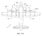
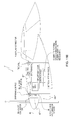
- Fig. 1 shows an aircraft 1 equipped with an automatic balancing system 10.
- the aircraft 1 has an aircraft propelling system 3 including at least a first propeller 12, and preferably with propelling system 3 comprised of multiple propeller systems 3' with propellers 12 and engines/gearboxes 18.
- the aircraft propelling system 3 includes a plurality of propeller systems 3'.
- the aircraft balancing system 10 includes a balancer assembly 110 coupled to propellers 12.
- the balancer assemblies 110 are controlled by a centralized global controlling first balancer control system 5 with centralized controller 20 controlling the plurality of balancer assemblies for each propeller.
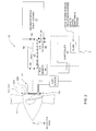
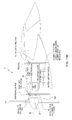
- Fig. 2 shows an aircraft balancing system 10.
- Aircraft balancing system 10 is coupled to a propeller 12 that is rotated by a rotating machine member shaft 47 coupled to a propeller engine/gearbox 18.
- Propeller 12, shaft 47 and engine/gearbox 18 provide an aircraft propelling system 3 that produces motive power for propelling the aircraft.
- propeller 12 can become imbalanced.
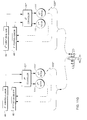
- the balancing system 10 includes a first control system 5 that includes one or more vibration sensors 44 for detecting an imbalance condition in a propeller 12 and propeller shaft 47 of the propeller system.
- the vibration sensors 44 are located on or proximate to the engine/gearbox 18, preferably with the vibration sensor comprised of an accelerometer radially oriented on the engine/gearbox 18 to measure a vibration 24 lateral to the shaft 47, preferably radially oriented vibration sensor 44 measuring lateral shaft vibration 24.
- the control system 5 includes one or more position sensors 46 for detecting the positions of adjustable balancing counterweight rotating balancing rotors of the balancer assembly 110.
- the position sensors 46 are located proximate to the balancer assembly 110 and proximate the adjustable balancing counterweight rotating balancing rotors whose counter weight rotational position is being measured, preferably with the position sensors 46 in the balancer assembly 110, preferably in the inboard electromagnetic coil driver 220, preferably Hall effect magnetic position sensors which are stationary with respect to the rotating machine member and mounted in close non-contacting proximity to the rotors, the output position sensor signals of the Hall effect device position sensors representative of shaft position and the positions of balancing ring rotors, with the magnetic position sensors producing a pulse that is proportional to the length of time that the particular position sensor is in proximity to the magnet targets located on the rotating members, with the rotating machine member shaft speed preferably computed by counting the rate of Hall effect sensor pulses caused by the passing rotating target, and angular position of each rotor relative to the rotating assembly measured by the phase shift between sensor pulses caused by magnetic targets on each rotor and pulses caused by the rotating magnetic target grounded to the rotating machine member shaft.
- the propeller balancer assembly preferably includes a plurality of balance correction rotating balancing rotors 111, 111' that are electromagnetically positional around the rotating machine member shaft 47 and the rotation axis 48.
- the positional rotating balancing rotors 111, 111' are weighted, and are selectively stepped and held with a pattern of inboard positioning magnets 112 to cooperatively correct an imbalanced condition of rotating propeller 12 and shaft 47.
- the invention includes methods of balancing aircraft propeller systems 3'.
- the methods preferably include providing an aircraft propeller system 3' with a rotating machine propeller shaft member 47 which rotates around a rotation axis 48.
- the method preferably includes providing a first counterweight rotating balancing rotor 111, the first counterweight heavy spot mass concentration balancing rotor including a first plurality of holding stepping inboard magnets 112.
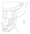
- FIG. 3 illustrates counterweight rotating balancing rotors 111, 111', the counterweight heavy spot mass concentration balancing rotor 111 preferably including a first plurality of holding stepping inboard magnets 112.
- the inboard magnets 112 are noncircular magnets, preferably longitudinally extending magnets.
- first counterweight heavy spot mass concentration balancing rotor 111 includes a first outboard heavy spot mass concentration 113.
- FIG. 3 illustrates counterweight rotating balancing rotor 111, 111' with a heavy spot mass concentration 113, preferably provided from relatively high density mass concentration inserts 114 and opposing mass voids 115.
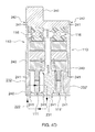
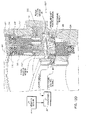
- FIG. 4 illustrates a crossection of first and second counterweight rotating balancing rotors 111, 111' in a welded casing, with the rotors movably positionable around the rotation axis 48 of a rotating machine member with the rotors including a plurality of patterned oriented inboard magnets 112 for electromagnetically actuated rotational movement around the rotation axis 48 of the rotating machine member for which the balancer is mounted.
- the outboard heavy spot mass concentrations 113 and the mass concentration inserts 114 and mass voids 115 are distal from the rotation axis 48 and the holding stepping inboard magnets 112 are proximate the rotation axis 48.
- the method preferably includes providing a second counterweight rotating balancing rotor 111', the second counterweight heavy spot mass concentration balancing rotor 111' including a second plurality of holding stepping inboard magnets 112 and a second outboard heavy spot mass concentration 113.
- the rotors 111, 111' are movably disposed upon the rotating machine member with the plurality of magnets 112 disposed inboard of the mass concentrations 113 and proximate the rotation axis 48 with the magnet pattern providing for electromagnetically actuated stepped rotational movement around the rotation axis 48 of the rotating machine member 47 for which the balancer is mounted.
- the outboard heavy spot mass concentrations 113 are distal from the rotation axis 48 as compared to the holding stepping inboard magnets 112 proximate the rotation axis 48.
- the method preferably includes providing an inboard nonrotating electromagnetic coil driver 220, the inboard electromagnetic coil driver 220 including a first inboard electromagnetic coil 221 proximate the rotation axis 48, and a second inboard electromagnetic coil 221' proximate the rotation axis 48, preferably with the inboard electromagnetic coils 221, 221' comprised of wound electrical conductors, preferably electrical conductor wires wound around a center oriented with the axis 48.
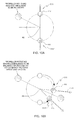
- 4C illustrates relationship of the relation of the pole patterns 233,233' of the center pole plate 231 to the north (N) and south (S) poles of the magnets 112 with the strong magnetic holding field of the magnets set up through and corresponding to the thick parts of the pole plate pattern compared to the thinned out parts of the pattern, and then when a timed quick short duration controlled magnetic field is generated by the proximate coil 221' with magnetic polarity generated in the thick parts of the pole pattern such that the S south pole of a magnet 112 is repelled by the proximate south pole generated in the thick part of the pole plate pattern by the EM coil controlled magnetic field and attracted by the north pole generated by the EM coil controlled magnetic field on the opposite side of the thinned part valley in the pattern with the rotor 111' magnetically stepped across this pole pattern thinned part valley.
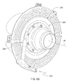
- FIG. 5 illustrates an inboard nonrotating EM coil driver 220 with a relatively smaller diameter for noncontactingly fitting concentrically inside a balancer casing 230 containing the counterweight rotating balancing rotors 111,111'.
- the method preferably includes disposing the inboard nonrotating electromagnetic coil driver 220 and the first counterweight balancing rotor 111 and the second counterweight balancing rotor 111' around the rotating machine propeller shaft member 47 with the first inboard electromagnetic coil 220 proximate the first inboard magnets 112 of the first counterweight balancing rotor 111, the inboard nonrotating electromagnetic coil driver 220 proximate the rotation axis 48 and the first counterweight balancing rotor 111 outboard of the inboard nonrotating electromagnetic coil driver 220 and distal from the rotation axis 48, with the first inboard electromagnetic coil 221 generating a electromagnetic field 222 when energized with an electrical current to electromagnetically step the first inboard magnets 112 of the at least first counterweight balancing rotor 111 to electromagnetically actuate rotational movement of the first counterweight heavy spot mass concentration
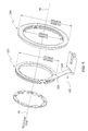
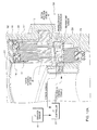
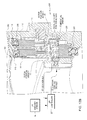
- FIG. 6 and 7 illustrate the position and orientation of the inboard nonrotating electromagnetic coil driver 220 and the outboard counterweight heavy spot mass concentration balancing rotors 111, 111'.
- the second inboard electromagnetic coil 221' is preferably proximate the second counterweight balancing rotor 111', with the second inboard electromagnetic coil 221' proximate the second inboard magnets 112 of the second counterweight balancing rotor 111', wherein the second inboard electromagnetic coil 221' generates an electromagnetic field 222 to electromagnetically step the second inboard magnets 112 of the second counterweight balancing rotor 111' to electromagnetically actuate rotational movement of the second counterweight heavy spot mass concentration balancing rotor 111' around the rotation axis 48 and relative to the inboard nonrotating electromagnetic coil driver 220.
- the inboard electromagnetic coil driver 220 includes a plurality of inboard bearing members 224, and the method includes rotationally supporting the inboard nonrotating electromagnetic coil driver 220 upon the rotating machine propeller shaft member 47 with the inboard bearing members 224.
- the EM coil driver 220 support bearing members 224 support the nonrotating coil driver 220 around the rotating machine member.
- the method includes restraining the inboard electromagnetic coil driver 220 from rotating around the rotation axis 48.
- restraining the inboard electromagnetic coil driver 220 from rotating around the rotation axis 48 includes providing a rotation restraint, and disposing the rotation restraint 226 proximate the inboard nonrotating electromagnetic coil driver 220 wherein the rotation restraint 226 physically grounds the inboard nonrotating electromagnetic coil driver 220 to a nonrotating machine member 50.
- the rotation restraint 226 includes at least one electrical conductor, and the method includes transmitting electricity through the rotation restraint 226 to the inboard nonrotating electromagnetic coil driver 220.
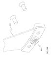
- the rotation restraint 226 is comprised of a torque arm 228 with the torque arm 228 including a printed circuit board 229 with the electrical conductors providing an electrical circuit to the nonrotating EM coil driver 220 for transmitting electricity.
- the aircraft propeller system comprises a propeller and an engine/gearbox with the rotating machine propeller shaft member coupling the propeller and the engine/gearbox.
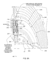
- the first counterweight rotating balancing rotor 111 is rotationally supported by a first rotor outboard rotating bearing support assembly 116 distal from the rotation axis 48
- the second counterweight rotating balancing rotor 111' is rotationally supported by a second rotor outboard rotating bearing support assembly 116 distal from the rotation axis 48 with the first and second counterweight rotating balancing rotors 111, 111' contained in a rotating outer casing 230
- the rotating outer casing 230 housing the rotating balancing rotors 111, 111', with the outer casing 230 mechanically grounded to the rotating machine propeller shaft member 47 with the first rotor outboard rotating bearing support assembly 116 between the first counterweight rotating balancing rotor 111 and an outboard circumference of the outer casing 230, and with the second rotor outboard rotating bearing support assembly 116 between the second counterweight rotating balancing rotor 111' and the outboard circumference of the outer casing 230.
- FIG. 6 illustrates the outboard rotating bearing support assemblies 116 and the grounded rotating casing 230.
- the rotating outer casing 230 including a rotating inboard center pole plate 231, and a first rotating outer pole plate 232, the first rotating outer pole plate 232 disposed relative to the rotating center pole plate 231 wherein the first counterweight rotating balancing rotor first plurality of holding stepping inboard magnets 112 are noncontactingly received between the first rotating outer pole plate and the rotating center pole plate.
- the rotating outer casing 230 further includes a second rotating outer pole plate, the second rotating outer pole plate 232' disposed relative to the rotating center pole plate 231 wherein the second counterweight rotating balancing rotor second plurality of holding stepping inboard magnets 112 are noncontactingly received between the second rotating outer pole plate 232' and the rotating center pole plate 231.
- the methods include maintaining a liquid lubricant sealed inside the rotating outer casing 230.
- the liquid lubricant fills the rotating outer casing 230.
- the liquid lubricant fills air void spaces inside the casing 230 and bathes the rotors and the outboard rotating bearing support assemblies.
- the sealed in liquid lubricant comprises a liquid oil, preferably a liquid oil having a viscosity in the range from 5 to 20 cst, preferably a non-grease liquid lubricant oil.
- the rotating outer casing 230 is comprised of a plurality of sealed welded outer casing members 240.
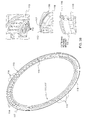
- FIG. 4 illustrates a casing weldment assembly with weld points 241 identified by triangles with the welds 241 welding together the outer casing members 240 to provide the sealed casing 230.
- the welded outer casing members 240 of the balancer casing 230 are united together with a plurality of welds 241, preferably from directed energy welding, preferably from energized beam welding, preferably electron beam welding, preferably vacuum electron beam welding.
- the plurality of outer casing members 240 have machine groove mating interface weld points, with the welding sealing the casing 230 with welds 241 proximate the mating interfaces, with the welded mating interface weld points sealing the casing 230 and containing the liquid lubricant.
- 4D illustrates a preferred welded rotating outer casing 230 and method of making a balancer and the rotating outer casing 230 with the outer casing members 240 including at least one decoupling void 242 in the outer casing member 240 proximate the welds 241.
- a decoupling void 242 is provided in outer perimeter ring outer casing member 240 proximate the welds 241 and the outer perimeter of the casing 230, with the decoupling void 242 preferably comprised of a groove running proximate the perimeter, with the decoupling void 242 inhibiting stress and strain distortion of the welded rotating outer casing 230
- the outer casing 230 members including the magnetic metal pole plates, including the center pole plate 231 and the two side pole plates 232,232' with the pole plate patterns for a rotor matching up, with the center pole plate 231 magnetic material metal relief cut thinned metal depression patterns 233, 233' staggered.
- the method preferably includes monitoring a plurality of rotating balancing rotor positions relative to the inboard nonrotating electromagnetic coil driver 220 to provide a monitored health performance failure detection characteristic of the aircraft system 3.
- the methods include performing an aircraft maintenance repair procedure in relationship to the monitored health performance failure detection characteristic of the aircraft propeller system 3'.
- the methods include monitoring a plurality of balancer sensor outputs to provide a monitored aircraft performance health failure detection characteristic, with the balancer sensor outputs preferably including sensor outputs selected from the sensor group including position, temperature, and vibration sensors.
- the invention includes an aircraft propelling system 3.
- the aircraft system including a rotating machine member 47 which rotates around a rotation axis 48, a first counterweight rotating balancing rotor 111, the first counterweight heavy spot mass concentration balancing rotor 111 including a first plurality of holding stepping inboard magnets 112, preferably the inboard magnets 112 are noncircular magnets, preferably longitudinally extending magnets, preferably longitudinally extending normal to the rotation axis 48, preferably the longitudinally extending magnets extend and are elongated and aligned with radii extending out from the rotation axis 48, and a first outboard heavy spot mass concentration.
- the rotor is movably disposed upon the machine and contains at least one magnet for electromagnetically actuated rotational movement around the rotation axis 48 of the rotating machine member for which the balancer is mounted.
- the outboard heavy spot mass concentration is distal from the rotation axis 48 and the holding stepping inboard magnets 112 are proximate the rotation axis 48.
- the system preferably includes a second counterweight rotating balancing rotor 111', the second counterweight heavy spot mass concentration balancing rotor 111' including a second plurality of holding stepping inboard magnets 112 and a second outboard heavy spot mass concentration.
- the second rotor 111' is movably disposed upon the machine and contains at least one magnet 112 for electromagnetically actuated rotational movement around the rotation axis 48 of the rotating machine member 47 for which the balancer 110 is mounted, preferably the outboard heavy spot mass concentration are distal from the rotation axis 48 and the holding stepping inboard magnets 112 are proximate the rotation axis 48.
- the system preferably includes an inboard nonrotating electromagnetic coil driver 220, the inboard electromagnetic coil driver 220 including a first inboard electromagnetic coil proximate the rotation axis 48, and a second inboard electromagnetic coil proximate the rotation axis 48, the inboard nonrotating electromagnetic coil driver 220 and the first counterweight balancing rotor 111 and the second counterweight balancing rotor 111' centered around the rotating machine member 47 with the first inboard electromagnetic coil 221 proximate the first inboard magnets 112 of the first counterweight balancing rotor 111, the inboard nonrotating electromagnetic coil driver 220 proximate the rotation axis 48 and the first counterweight balancing rotor 111 outboard of the inboard nonrotating electromagnetic coil driver 220 and distal from the rotation axis 48.
- the inboard electromagnetic coil driver 220 including a first inboard electromagnetic coil proximate the rotation axis 48, and a second inboard electromagnetic coil proximate the rotation axis 48, the inboard
- the first inboard electromagnetic coil 221 generating a electromagnetic field to electromagnetically step the first inboard magnets 112 of the at least first counterweight balancing rotor 111 to electromagnetically actuate rotational movement of the first counterweight heavy spot mass concentration balancing rotor around the rotation axis 48 and around the rotating machine member 47 and relative to the inboard nonrotating electromagnetic coil driver 220 to a first rotor held balancing position.
- the second inboard electromagnetic coil 221' is proximate the second counterweight balancing rotor 111', with the second inboard electromagnetic coil 221' proximate the second inboard magnets 112 of the second counterweight balancing rotor 111', wherein the second inboard electromagnetic coil 221' generates an electromagnetic field to electromagnetically step the second inboard magnets 112 of the second counterweight balancing rotor 111' to electromagnetically actuate rotational movement of the second counterweight heavy spot mass concentration balancing rotor 111' around the rotation axis 48 and relative to the inboard nonrotating electromagnetic coil driver 220 to a second rotor held position.
- the inboard electromagnetic coil driver 220 includes a plurality of inboard bearing members 224 rotationally supporting the inboard nonrotating electromagnetic coil driver 220 upon the rotating machine member 47, preferably with the coil support bearing members supporting the nonrotating coil driver 220 around the rotating machine member.
- the system includes a rotation restraint 226, the rotation restraint 226 disposed proximate the inboard nonrotating electromagnetic coil driver 220 wherein the rotation restraint 226 physically grounds the inboard nonrotating electromagnetic coil driver 220 to a nonrotating machine member 50.
- the system rotation restraint 226 includes an electrical circuit ,preferably a printed circuit board 229, transmitting electricity through the rotation restraint.
- the system includes the first counterweight rotating balancing rotor 111 rotationally supported by a first rotor outboard rotating bearing support assembly 116 distal from the rotation axis 48, and the second counterweight rotating balancing rotor 111' is rotationally supported by a second rotor outboard rotating bearing support assembly 116 distal from the rotation axis 48 with the first and second counterweight rotating balancing rotors contained in a rotating outer casing 230, the rotating outer casing 230 housing the rotating balancing rotors 111, 111', with the outer casing 230 mechanically grounded to the rotating machine member 47 with the first rotor outboard rotating bearing support assembly 116 between the first counterweight rotating balancing rotor 111 and an outboard circumference of the outer casing 230, and with the second rotor outboard rotating bearing support assembly 116 between the second counterweight rotating balancing rotor 111' and the outboard circumference of the outer casing 230.
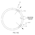
- the balancer system counterweight rotating balancing rotors 111, 111' have rotor outboard rotating bearing support assemblies 116 with thin section bearings with rollers and proximate the outer perimeter of casing 230, preferably with oriented arc integral machined bearing support flange 117 oriented relative to the heavy spot mass concentration 113 and the mass concentrations 114.
- the oriented arc integral machined bearing support flange 117 has an arc less than 180 degrees, preferably less than 165 degrees, preferably in the range from about 150 to 120 degrees, and preferably about 146 degrees.
- the arc is centered about the heavy spot mass concentration, and preferably opposes the mass voids 115 side of the rotors 111, 111'.
- the rotor oriented arc integral machined bearing support flange 117 is provided as an integral feature of the rotor structure, preferably during the forming process of the rotor structure, preferably during machining of the rotor structure, and then during bearing 116 insertion, the bearing ring assembly with the rollers and inner and outer races are snap fitted around and past the rotor oriented arc integral machined bearing support flange 117, which is then followed by placement and fastening of nonintegral fastener bearing flange 118 around the remaining majority of the perimeter of the rotor.
- the oriented arc integral machined bearing support flange 117 and fastener bearing flange 118 capture the bearing assembly 116 axially.
- the rotating outer casing 230 including a rotating inboard center pole plate 231, and a first rotating outer pole plate 232, the first rotating outer pole plate 232 disposed relative to the rotating center pole plate 231 wherein the first counterweight rotating balancing rotor first plurality of holding stepping inboard magnets 112 are noncontactingly received between the first rotating outer pole plate 232 and the rotating center pole plate 231.
- the rotating outer casing 230 further includes a second rotating outer pole plate 232', the second rotating outer pole plate 232' disposed relative to the rotating center pole plate 231 wherein the second counterweight rotating balancing rotor second plurality of holding stepping inboard magnets 112 noncontactingly received between the second rotating outer pole plate 232' and the rotating center pole plate 231.
- the system includes a liquid lubricant sealed inside the rotating outer casing 230.
- the liquid lubricant fills the rotating outer casing 230 and fills air void spaces inside the casing 230 and bathes the rotors and the outboard rotating bearing support assemblies.
- the sealed in liquid lubricant comprises a liquid oil, preferably having a viscosity in the range from 5 to 20 cst, preferably a non-grease liquid lubricant.
- the rotating outer casing 230 is comprised of a plurality of sealed welded outer casing members 240.
- welding outer casing members together with a plurality of welds 241 includes, preferably energized beam welding, preferably electron beam welding, preferably vacuum electron beam welding are utilized to bond the casing members 240 together, preferably with the plurality of outer casing members 240 having machine groove mating interface weld points, with the welding 241 sealing the casing 230 proximate the mating interfaces.
- the welded united outer casing members 240 include the magnetic metal pole plates.
- the invention includes an electromagnetically actuated machine balancer 110 for mounting on a rotating machine member 47 and balancing the rotating machine member.
- the electromagnetically actuated balancer 110 preferably comprises at least a first counterweight heavy spot mass concentration rotating balancing rotor 111, the first counterweight heavy spot mass concentration balancing rotor 111 including a first plurality of holding stepping inboard magnets 112 and a first outboard heavy spot mass concentration.
- the rotor 111 is movably disposed upon the machine 47 and contains a pattern of magnets 112 for electromagnetically actuated rotational movement around the rotation axis 48 of the rotating machine member 47 for which the balancer 110 is mounted, preferably with outboard heavy spot mass concentration distal from the rotation axis 48 and the holding stepping inboard magnets 112 proximate the rotation axis 48.
- the electromagnetically actuated balancer 110 preferably comprises an inboard nonrotating electromagnetic coil driver 220, the inboard electromagnetic coil driver 220 including at least a first inboard electromagnetic coil 221 proximate the rotation axis 48, the first inboard electromagnetic coil 221 proximate the first inboard magnets 112 of the counterweight balancing rotor 111, wherein the first inboard electromagnetic coil 221 generates an electromagnetic field to electromagnetically step the first inboard magnets 112 of the at least first counterweight balancing rotor 111 to electromagnetically actuate rotational movement of the first counterweight heavy spot mass concentration balancing rotor 111 around the rotation axis 48 and relative to the inboard nonrotating electromagnetic coil driver 220.
- the bearing members between the inboard nonrotating electromagnetic coil driver 220 and the rotating machine member 47 Preferably with the inboard electromagnetic coil driver 220 including a plurality of inboard bearing members 224, the bearing members between the inboard nonrotating electromagnetic coil driver 220 and the rotating machine member 47, preferably with the coil support bearing members 224 supporting the nonrotating coil driver 220 around the rotating machine member 47.
- the bearing members 224 include a plurality of inboard roller bearings between the first inboard electromagnetic coil 221 and the rotation axis 48.
- the electromagnetically actuated machine balancer 110 includies a rotation restraint 226, the rotation restraint 226 physically grounding the inboard nonrotating electromagnetic coil driver 220 to a nonrotating machine member 50, preferably a restraining yoke, preferably a movable rotation restraint antitorque tie rod 226 providing a level of decoupled motion between inboard nonrotating electromagnetic coil driver 220 and the nonrotating machine member 50, with a mechanical physical play yoke or motion accomadating mount, preferably with the antitorque tie rod restraint 226 providing electrical power and signals to the balancer and also carrying an axial mechanical load, preferably through the printed circuit board 229.
- the restraint includes snapon snapoff mating electrical disconnectable connectors 225,225' for connecting and disconnecting the electrical circuits of antitorque tie rod restraining circuit board 229 to nonrotating electrical wiring conduits mechanically grounded with nonrotating machine member 50.
- the restraint is a torque arm 228 with elastomeric mounting members 227, preferably with the torque arm 228 physically and electrically connecting to the coil driver 220.
- the balancer 110 includes a second counterweight heavy spot mass concentration rotating balancing rotor 111', the second counterweight heavy spot mass concentration balancing rotor 111' including a second plurality of holding stepping inboard magnets 112 and a second outboard heavy spot mass concentration, preferably with the rotor 111' movably disposed upon the machine and containing at least one magnet 112 for electromagnetically actuated rotational movement around the rotation axis 48 of the rotating machine member 47 for which the balancer is mounted, preferably with the outboard heavy spot mass concentration distal from the rotation axis 48 and the holding stepping inboard magnets 112 proximate the rotation axis 48.
- the inboard electromagnetic coil driver 220 including a second inboard electromagnetic coil 221' proximate the rotation axis 48, the second inboard electromagnetic coil 221' proximate the second inboard magnets 112 of the second counterweight balancing rotor 111', wherein the second inboard electromagnetic coil 221' generates an electromagnetic field to electromagnetically step the second inboard magnets 112 of the second counterweight balancing rotor 111' to electromagnetically actuate rotational movement of the second counterweight heavy spot mass concentration balancing rotor 111' around the rotation axis 48 and relative to the inboard nonrotating electromagnetic coil driver 220.
- the inboard magnets 112 are noncircular magnets 112, preferably longitudinally extending magnets 112, preferably longitudinally extending normal to the rotation axis 48, preferably the longitudinally extending magnets 112 extend and are elongated and aligned with radii extending out from the rotation axis 48.
- the balancer 110 includes a rotating center pole plate 231, the rotating center pole plate 231 disposed between the first counterweight heavy spot mass concentration rotating balancing rotor 111 and the second counterweight heavy spot mass concentration rotating balancing rotor 111', the rotating center pole plate 231 physically grounded to the rotating machine member 47 wherein the rotating center pole plate 231 rotates along with the rotating machine member 47 around the rotation axis 48 and provides a grounded rotating holding stepping reference point for the first counterweight heavy spot mass concentration rotating balancing rotor 111 and the second counterweight heavy spot mass concentration rotating balancing rotor 111' to rotate relative to around the rotation axis 48 preferably with an actuation push off point when the coil magnet fields are generated, and the rotors 111,111' are stepped relative to the pole plates 231, 232, 232' and then held at such position until the next activating balance need, preferably the rotors 111, 111' are intermittingly rotated relative to the rotating machine member 47 and rested and held at
- the balancer includes a first rotating outer pole plate 232 with a pattern 234 of poles, the first rotating outer pole plate 232 disposed relative to the rotating center pole plate 231 wherein the first counterweight rotating balancing rotor first plurality of holding stepping inboard magnets 112 are noncontactingly received between the first rotating outer pole plate 232 and the rotating center pole plate 231 , with the rotating center pole plate 231 preferably having a first pole face side, the first pole face side facing the first rotating outer pole plate 232 with a pattern 233 of poles, preferably with the pattern 233 of poles preferably provided by a thinning of magnetic pole plate material, preferably with a magnetic metal pole plate with a pattern 233 of thinned metal depressions.
- the balancer 110 includes a second rotating outer pole plate 232', the second rotating outer pole plate 232' disposed relative to the rotating center pole plate 231 wherein the second counterweight rotating balancing rotor second plurality of holding stepping inboard magnets 112 are noncontactingly received between the second rotating outer pole plate 232' and the rotating center pole plate 231, preferably the rotating center pole plate 231 preferably having a second pole face side, the second pole face side facing the second rotating outer pole plate 232' with a pattern 233' of poles, the second pole face side pattern 233' clockingly staggered relative to the first face side pattern 233, preferably with the pattern of poles preferably provided by a thinning of magnetic pole plate material, preferably a magnetic metal pole plate with pattern of thinned metal depressions.
- the rotating center pole plate 231 preferably having consistent offset staggered poles, one side pole pattern of depression thinned metal staggered relative to the opposite face side.
- the pole plate patterns 233,233' are formed from thin metal depressions, preferably not through cuts of metal material, preferably not through holes/notches all the way through the magnetic material.
- the first counterweight heavy spot mass concentration rotating balancing rotor 111 is rotationally supported by a first rotor outboard rotating bearing support assembly 116.
- the rotor 111 is contained in a rotating outer casing 230, the rotating outer casing 230 housing the rotor 111, with the outer casing 230 physically mechanically grounded mounted to the rotating machine member.
- the rotating outer casing 230 includes a plurality of rotating inboard pole plates 231, 232,232' for noncontactingly and magnetically receiving the rotor magnets 112.
- the first counterweight heavy spot mass concentration rotating balancing rotor 111 is rotationally supported by a first rotor outboard rotating bearing support assembly 116 distal from the rotation axis 48
- the second counterweight heavy spot mass concentration rotating balancing rotor 111' is rotationally supported by a second rotor outboard rotating bearing support assembly 116 distal from the rotation axis 48, preferably with the first and second counterweight rotating balancing rotors 111,111' contained in a rotating outer casing 230, the rotating outer casing 230 housing the rotating balancing rotors, with the outer casing 230 physically mechanically grounded mounted to the rotating machine member 47.
- the rotating outer casing 230 includes a rotating inboard center pole plate231, and a first rotating outer pole plate 232, the first rotating outer pole plate 232 disposed relative to the rotating center pole plate 231 wherein the first counterweight rotating balancing rotor first plurality of holding stepping inboard magnets 112 are noncontactingly received between the first rotating outer pole plate 232 and the rotating center pole plate 231, preferably the rotating outer casing 230 further includes a second rotating outer pole plate 232', the second rotating outer pole plate 232' disposed relative to the rotating center pole plate 231 wherein the second counterweight rotating balancing rotor second plurality of holding stepping inboard magnets 112 are noncontactingly received between the second rotating outer pole plate 232' and the rotating center pole plate 231.
- the first counterweight heavy spot mass concentration rotating balancing rotor 111 has an outside diameter FCWROD and the first inboard electromagnetic coil 221 has an outside diameter FEMCOD with FEMCOD ⁇ FCWROD.
- the first counterweight heavy spot mass concentration rotating balancing rotor 111 has an inside diameter FCWRID with FCWRID> FEMCOD.
- the second counterweight heavy spot mass concentration rotating balancing rotor 111' has an outside diameter SCWROD and an inside diameter SCWRID and the second inboard electromagnetic coil 221' has an outside diameter SEMCOD with SEMCOD ⁇ SCWROD, and SEMCOD ⁇ SCWRID.
- the first counterweight rotating balancing rotor 111 is rotationally supported by a first rotor outboard rotating bearing support assembly 116 distal from the rotation axis 48
- the second counterweight rotating balancing rotor 111' is rotationally supported by a second rotor outboard rotating bearing support assembly 116 distal from the rotation axis 48 with the first and second counterweight rotating balancing rotors 111, 111' contained in a rotating outer casing 230
- the rotating outer casing 230 housing the rotating balancing rotors 111, 111', with the outer casing 230 mechanically grounded to the rotating machine member 47 with the first rotor outboard rotating bearing support assembly 116 between the first counterweight rotating balancing rotor 111 and an outboard circumference of the outer casing 230
- the second rotor outboard rotating bearing support assembly 116 between the second counterweight rotating balancing rotor 111' and the outboard circumference of the outer casing 230 (preferably the rotating outer casing 230 including
- a liquid lubricant is sealed inside the rotating outer casing 230.
- the liquid lubricant fills the rotating outer casing 230 and fills air void spaces inside the casing 230 and bathes the rotors and the outboard rotating bearing support assemblies.
- the sealed in liquid lubricant comprises a liquid oil, preferably having a viscosity in the range from 5 to 20 cst, preferably a non-grease liquid lubricant.
- the invention includes a method of making an electromagnetically actuated machine balancer 110 for mounting on a rotating machine member 47 and balancing the rotating machine member.
- the method of making an electromagnetically actuated machine balancer for mounting on a rotating machine member provides a preferred means for actively balancing aircraft rotating machine members.
- the method includes providing a first counterweight heavy spot mass concentration rotating balancing rotor 111, the first counterweight heavy spot mass concentration balancing rotor 111 including a first plurality of holding stepping inboard magnets 112, preferably the inboard magnets 112 are noncircular magnets 112, preferably longitudinally extending magnets 112, preferably longitudinally extending normal to the rotation axis 48, preferably the longitudinally extending magnets 112 extend and are elongated and aligned with radii extending out from the rotation axis 48 and first outboard heavy spot mass concentration outboard heavy spot mass concentration distal from the rotation axis 48 and the holding stepping inboard magnets 112 proximate the rotation axis 48.
- the method includes providing an inboard nonrotating electromagnetic coil driver 220, the inboard electromagnetic coil driver 220 including at least a first inboard electromagnetic coil 221 proximate the rotation axis 48.
- the method includes disposing the first inboard electromagnetic coil 221 proximate the first inboard magnets 112 of the counterweight balancing rotor 111, wherein the first inboard electromagnetic coil 221 generates a magnet field to electromagnetically step the first inboard magnets 112 of the at least first counterweight balancing rotor 111 to electromagnetically actuate rotational movement of the first counterweight heavy spot mass concentration balancing rotor 111 around the rotation axis 48 relative to the inboard nonrotating electromagnetic coil driver 220.
- the inboard electromagnetic coil driver 220 includes a plurality of inboard bearing members 224, the bearing members for rotationally supporting the inboard nonrotating electromagnetic coil driver 220 around a rotating machine member 47, the coil support bearing members 224 supporting the nonrotating coil driver 220 around the rotating machine member.
- the inboard bearing members 224 include a plurality of inboard roller bearings between the first inboard electromagnetic coil and a rotation axis 48 of the balancer.
- the method includes providing a rotation restraint 226, and disposing the rotation restraint 226 proximate the inboard nonrotating electromagnetic coil driver 220 wherein the rotation restraint 226 physically grounds the inboard nonrotating electromagnetic coil driver 220 to a nonrotating machine member 50.
- the rotation restraint 226 is an anti-torque arm 228 restraining yoke, preferably a movable rotation restraint 226 providing a level of decoupled motion between inboard nonrotating electromagnetic coil driver 220 and the nonrotating machine member, mechanical physical play yoke or motion accomadating mount, preferably a torque arm 228 with elastomeric mounting members 227, preferably with the torque arm 228 physically and electrically connecting to the coil driver 220.
- the method includes providing a second counterweight heavy spot mass concentration rotating balancing rotor 111', the second counterweight heavy spot mass concentration balancing rotor 111' including a second plurality of holding stepping inboard magnets 112 and a second outboard heavy spot mass concentration.
- the rotor 111' is movably disposed upon the machine 47 and containing at least one magnet 112 for electromagnetically actuated rotational movement around the rotation axis 48 of the rotating machine member 47 for which the balancer is mounted, with the outboard heavy spot mass concentration distal from the rotation axis 48 and the holding stepping inboard magnets 112 proximate the rotation axis 48.
- the method includes providing a second inboard electromagnetic coil 221' proximate the rotation axis 48, disposing the second inboard electromagnetic coil 221' proximate the second inboard magnets 112 of the second counterweight balancing rotor 111', wherein the second inboard electromagnetic coil 221' generates a magnet field 222 to electromagnetically step the second inboard magnets 112 of the second counterweight balancing rotor to electromagnetically actuate rotational movement of the second counterweight heavy spot mass concentration balancing rotor around the rotation axis 48 and relative to the inboard nonrotating electromagnetic coil driver 220.
- the method including providing a rotating center pole plate 231, disposing the rotating center pole plate 231 between the first counterweight heavy spot mass concentration rotating balancing rotor 111 and the second counterweight heavy spot mass concentration rotating balancing rotor 111', the rotating center pole plate 231 physically groundable to a rotating machine member 47 wherein the rotating center pole plate 231 rotates along with the rotating machine member 47 around a rotation axis 48 to provide a grounded rotating holding stepping reference point for the first counterweight heavy spot mass concentration rotating balancing rotor 111 and the second counterweight heavy spot mass concentration rotating balancing rotor 111' to rotate relative to around the rotation axis 48, with actuation push off points when the coil magnet fields 222 are generated, with the rotors 111, 111' stepped relative to the pole plate 231 and then held at such position until the next activating balance need, preferably rotors 111,111' are intermittingly rotated relative to the rotating machine member 47 and rested and held at a balance position around the rotating
- the first rotating outer pole plate 232 with a pattern 234 of poles, with the first rotating outer pole plate 232 disposed relative to the rotating center pole plate 231 wherein the first counterweight rotating balancing rotor first plurality of holding stepping inboard magnets 112 are noncontactingly received between the first rotating outer pole plate 232 and the rotating center pole plate 231.
- the rotating center pole plate 231 preferably has a first pole face side, the first pole face side facing the first rotating outer pole plate 232 with a pattern 233 of poles, with the pattern 233 of poles preferably provided by a thinning of magnetic pole plate material, preferably magnetic metal pole plate 231 with a pattern 233 of thinned metal depressions.
- the second rotating outer pole plate 232' is disposed relative to the rotating center pole plate 231 wherein the second counterweight rotating balancing rotor second plurality of holding stepping inboard magnets 112 are noncontactingly received between the second rotating outer pole plate 232' and the rotating center pole plate 231, and the rotating center pole plate 231 preferably having a second pole face side, the second pole face side facing the second rotating outer pole plate 232' with a pattern 232' of poles, the second pole face side pattern 232' clockingly staggered relative to the first face side pattern 232, with the pattern of poles 232' preferably provided by a thinning of magnetic pole plate material, preferably magnetic metal pole plate 231 with pattern of thinned metal depression.
- the rotating center pole plate 231 preferably having consistent offset staggered poles, one side pole pattern 232 of depression thinned metal staggered relative to the opposite face side pattern 232', preferably the pole plate patterns 232,232' formed from thin metal depressions, preferably not through cuts of metal material, preferably not through holes/notches all the way through the magnetic material.
- the method preferably includes providing a first rotor outboard rotating bearing support assembly 116 wherein the first counterweight heavy spot mass concentration rotating balancing rotor 111 is rotationally supported by the first rotor outboard rotating bearing support assembly 116.
- the rotating outer casing 230 housing the rotor 111, with the outer casing 230 physically mechanically grounded mounted to the rotating machine member 47, preferably the rotating outer casing 230 including a plurality of rotating inboard pole plates 231, 232, 232' for noncontactingly and magnetically receiving the rotor magnets 112.
- the method preferably including providing a first rotor outboard rotating bearing support assembly 116 wherein the first counterweight heavy spot mass concentration rotating balancing rotor 111 is rotationally supported by the first rotor outboard rotating bearing support assembly 116 distal from the rotation axis 48, and providing a second rotor outboard rotating bearing support assembly 116 wherein the second counterweight heavy spot mass concentration rotating balancing rotor 111' is rotationally supported by the second rotor outboard rotating bearing support assembly 116 distal from the rotation axis 48.
- the first and second counterweight rotating balancing rotors 111, 111' are contained in a rotating outer casing 230, the rotating outer casing 230 housing the rotating balancing rotors 111, 111', with the outer casing 230 physically mechanically grounded mounted to the rotating machine member 47.
- the rotating outer casing 230 including a rotating inboard center pole plate 231, and a first rotating outer pole plate 232, the first rotating outer pole plate 232 disposed relative to the rotating center pole plate 231 wherein the first counterweight rotating balancing rotor first plurality of holding stepping inboard magnets 112 are noncontactingly received between the first rotating outer pole plate 232 and the rotating center pole plate 231, preferably the rotating outer casing 230 further includes a second rotating outer pole plate 232', the second rotating outer pole plate 232' disposed relative to the rotating center pole plate 231 wherein the second counterweight rotating balancing rotor second plurality of holding stepping inboard magnets 112 are noncontactingly received between the second rotating outer pole plate 232' and the rotating center pole plate 231.
- the first counterweight heavy spot mass concentration rotating balancing rotor 111 has an outside diameter FCWROD and the first inboard electromagnetic coil 221 has an outside diameter FEMCOD with FEMCOD ⁇ FCWROD.
- the first counterweight heavy spot mass concentration rotating balancing rotor 111 has an inside diameter FCWRID with FCWRID> FEMCOD.
- the second counterweight heavy spot mass concentration rotating balancing rotor 111' has an outside diameter SCWROD and an inside diameter SCWRID and the second inboard electromagnetic coil 221' has an outside diameter SEMCOD with SEMCOD ⁇ SCWROD, and SEMCOD ⁇ SCWRID.
- the first counterweight rotating balancing rotor 111 is rotationally supported by a first rotor outboard rotating bearing support assembly 116 distal from the rotation axis 48
- the second counterweight rotating balancing rotor 111' is rotationally supported by a second rotor outboard rotating bearing support assembly 116 distal from the rotation axis 48 with the first and second counterweight rotating balancing rotors 111, 111' contained in a rotating outer casing 230
- the rotating outer casing 230 housing the rotating balancing rotors 111, 111', with the outer casing 230 mechanically grounded to the rotating machine member 47 with the first rotor outboard rotating bearing support assembly 116 between the first counterweight rotating balancing rotor 111 and an outboard circumference of the outer casing 230, and with the second rotor outboard rotating bearing support assembly 116 between the second counterweight rotating balancing rotor 111' and the outboard circumference of the outer casing 230.
- the rotating outer casing 230 including a rotating inboard center pole plate 231, and a first rotating outer pole plate 232, the first rotating outer pole plate 232 disposed relative to the rotating center pole plate 231 wherein the first counterweight rotating balancing rotor first plurality of holding stepping inboard magnets 112 are noncontactingly received between the first rotating outer pole plate 232 and the rotating center pole plate 231, preferably the rotating outer casing 230 further includes a second rotating outer pole plate 232', the second rotating outer pole plate 232' disposed relative to the rotating center pole plate 231 wherein the second counterweight rotating balancing rotor second plurality of holding stepping inboard magnets 112 are noncontactingly received between the second rotating outer pole plate 232' and the rotating center pole plate 231.
- a liquid lubricant is sealed inside the rotating outer casing 230.
- the liquid lubricant filling the rotating outer casing 230 and fluidly communicating air void spaces inside the casing 230 and bathes the rotors and the outboard rotating bearing support assemblies 116.
- the sealed in liquid lubricant comprises a liquid oil, preferably having a viscosity in the range from 5 to 20 cst, preferably a non-grease liquid lubricant.
- the rotating outer casing 230 is comprised of a plurality of outer casing members 240, with the method including uniting the outer casing members 240, preferably by welding the outer casing members 240 together with a plurality of welds 241, preferably with energized beam welding, preferably with electron beam welding, preferably with vacuum electron beam welding, preferably with the plurality of outer casing members 240 having machine groove mating interface weld points, with the weldings 241 sealing the casing 230 proximate the mating interfaces of the outer casing members 240, preferably with the outer casing members 240 including the magnetic metal pole plates.
- the invention includes a method of electromagnetically balancing an aircraft rotating machine member 47 which rotates about a rotation axis 48.
- the method preferably includes providing a first counterweight heavy spot mass concentration rotating balancing rotor 111, the first counterweight heavy spot mass concentration balancing rotor 111 including a first plurality of holding stepping inboard magnets 112, preferably the inboard magnets 112 are noncircular magnets 112, preferably longitudinally extending magnets 112, preferably longitudinally extending normal to the rotation axis 48, preferably the longitudinally extending magnets 112 extend and are elongated and aligned with radii extending out from the rotation axis 48 and a first outboard heavy spot mass concentration.
- the rotor 111 movably disposed upon the machine 47 and containing at least one magnet 112 for electromagnetically actuated rotational movement around the rotation axis 48 of the rotating machine member 47 for which the balancer 110 is mounted, the outboard heavy spot mass concentration distal from the rotation axis 48 and the holding stepping inboard magnets 112 proximate the rotation axis 48.
- the method preferably includes providing an inboard nonrotating electromagnetic coil driver 220, the inboard electromagnetic coil driver 220 including at least a first inboard electromagnetic coil 221 proximate the rotation axis 48.
- the method preferably includes disposing the inboard nonrotating electromagnetic coil driver 220 and the first counterweight balancing rotor 111 around the rotating machine member 47 with the first inboard electromagnetic coil 221 proximate the first inboard magnets 112 of the first counterweight balancing rotor, the inboard nonrotating electromagnetic coil driver 220 proximate the rotation axis 48 and the first counterweight balancing rotor 111 outboard of the inboard nonrotating electromagnetic coil driver 220 distal from axis 48 wherein the first inboard electromagnetic coil 221 generates a electromagnetic field 222 to electromagnetically step the first inboard magnets 112 of the at least first counterweight balancing rotor 111 to electromagnetically actuate rotational movement of the first counterweight heavy spot mass concentration balancing rotor 111 around the rotation axis 48 around the rotating machine member 47 and relative to the inboard nonrotating electromagnetic coil driver 220.
- the inboard electromagnetic coil driver 220 includes a plurality of inboard bearing members 224, the inboard bearing members 224 rotationally supporting the inboard nonrotating electromagnetic coil driver 220 upon the rotating machine member 47, the coil support bearing members 224 supporting the nonrotating coil driver 220 around the rotating machine member 47.
- the inboard bearing members 224 include a plurality of inboard roller bearings between the first inboard electromagnetic coil 221 and the rotation axis 48.
- the method includes providing a rotation restraint 226, and disposing the rotation restraint 226 proximate the inboard nonrotating electromagnetic coil driver 220 wherein the rotation restraint 226 physically grounds the inboard nonrotating electromagnetic coil driver 220 to a nonrotating machine member 50, preferably an anti-torque arm 228 restraining yoke, preferably a movable rotation restraint 226 providing a level of decoupled motion between inboard nonrotating electromagnetic coil driver 220 and the nonrotating machine member, mechanical physical play yoke or motion accomadating mount, preferably a torque arm 228 with elastomeric mounting members, preferably with the torque arm 228 physically and electrically connecting to the coil driver 220.
- a nonrotating machine member 50 preferably an anti-torque arm 228 restraining yoke, preferably a movable rotation restraint 226 providing a level of decoupled motion between inboard nonrotating electromagnetic coil driver 220 and the nonrotating machine member, mechanical
- the method includes providing a second counterweight heavy spot mass concentration rotating balancing rotor 111', the second counterweight heavy spot mass concentration balancing rotor 111' including a second plurality of holding stepping inboard magnets 112 and a second outboard heavy spot mass concentration, the rotor movably disposed upon the machine 47 and containing at least one magnet 112 for electromagnetically actuated rotational movement around the rotation axis 48 of the rotating machine member 47 for which the balancer is mounted, the outboard heavy spot mass concentration distal from the rotation axis 48 and the holding stepping inboard magnets 112 proximate the rotation axis 48.
- the method includes providing a second inboard electromagnetic coil 221' proximate the rotation axis 48, disposing the second inboard electromagnetic coil 221' and second counterweight balancing rotor 111' proximate the first inboard electromagnetic coil 221 and the first counterweight balancing rotor 111, with the second inboard electromagnetic coil 111' proximate the second inboard magnets 112 of the second counterweight balancing rotor 111', wherein the second inboard electromagnetic coil 221' generates an electromagnetic field 222 to electromagnetically step the second inboard magnets 112 of the second counterweight balancing rotor 111' to electromagnetically actuate rotational movement of the second counterweight heavy spot mass concentration balancing rotor 111' around the rotation axis 48 and relative to the inboard nonrotating electromagnetic coil driver 220.
- the method includes providing a rotating center pole plate 231, and disposing the rotating center pole plate 231 between the first counterweight heavy spot mass concentration rotating balancing rotor 111 and the second counterweight heavy spot mass concentration rotating balancing rotor 111', the rotating center pole plate 231 physically grounded to the rotating machine member 47 wherein the rotating center pole plate 231 rotates along with the rotating machine member 47 around the rotation axis 48 and provides a grounded rotating holding stepping reference point for the first counterweight heavy spot mass concentration rotating balancing rotor 111 and the second counterweight heavy spot mass concentration rotating balancing rotor 111' to rotate relative to around the rotation axis 48 with an actuation push off point when the EM coil magnet fields 222 are generated.
- the rotors 111,111' are stepped relative to the pole plates and then held at such position until the next activating balance need, preferably the rotors 111,111' are intermittingly rotated relative to the rotating machine member and rested and held at a balance position around the rotating machine with the balance force vectors of the held/resting rotor resulting in a balancing vector cancelling an inbalance force vector of the rotating machine, preferably with the rotors are not continually electromagnetically actuated and continually driven to rotate continuously relative to the rotating pole plate and its grounding rotating machine member and the rotating member, preferably inhibiting generating of a continuous circular rotating force vector.
- the casing 230 preferably includes a first rotating outer pole plate 232 with a pattern 234 of poles, the first rotating outer pole plate 232 disposed relative to the rotating center pole plate 231 wherein the first counterweight rotating balancing rotor first plurality of holding stepping inboard magnets 112 are noncontactingly received between the first rotating outer pole plate 232 and the rotating center pole plate 231, preferably with the rotating center pole plate 231 preferably having a first pole face side, the first pole face side facing the first rotating outer pole plate 232 with a pattern 233 of poles, the pattern 233 of poles preferably provided by a thinning of magnetic pole plate material, preferably a magnetic metal pole plate with a pattern 233 of thinned metal depressions.
- the casing 230 preferably includes a second rotating outer pole plate 232', the second rotating outer pole plate 232' disposed relative to the rotating center pole plate 231 wherein the second counterweight rotating balancing rotor second plurality of holding stepping inboard magnets 112 are noncontactingly received between the second rotating outer pole plate 232' and the rotating center pole plate 231, the rotating center pole plate 231 preferably having a second pole face side, the second pole face side facing the second rotating outer pole plate 232' with a pattern 233' of poles, the second pole face side pattern 233' clockingly staggered relative to the first face side pattern 233, preferably a pattern of poles preferably provided by a thinning of magnetic pole plate material, preferably a magnetic metal pole plate with pattern of thinned metal depressions 233,233'.
- the rotating center pole plate 231 preferably having consistent offset staggered poles 233,233', one side pole pattern 233 of depression thinned metal staggered relative to the opposite face side 233', preferably pole plate patterns formed from thin metal depressions, preferably not through cuts of metal material (preferably not through holes/notches all the way through the magnetic material).
- the method includes providing at least a first rotor outboard rotating bearing support assembly 116 wherein the first counterweight heavy spot mass concentration rotating balancing rotor 111 is rotationally supported by the first rotor outboard rotating bearing support assembly 116.
- the rotors 111,111' are contained in a rotating outer casing 230, the rotating outer casing 230 housing the rotors 111,111', with the outer casing 230 physically mechanically grounded mounted to the rotating shaft machine member rotating 47, preferably with the rotating outer casing 230 including a plurality of rotating inboard pole plates 231,232,232'proximate the rotation axis 48 for noncontactingly and magnetically receiving the rotor magnets 112, with the pole plates magnetic pattern receiving the magnetic pattern of the rotor's magnets 112, and channeling the electromagnetic field 222 of the proximate electromagnetic coil of the driver 220 to provide stepping actuation of the rotor and position holding of the rotor relative to the outer casing 230 physically mechanically grounded mounted rotating in
- the method includes providing a first rotor outboard rotating bearing support assembly 116 wherein the first counterweight heavy spot mass concentration rotating balancing rotor 111 is rotationally supported by the first rotor outboard rotating bearing support assembly distal 116 from the rotation axis 48, and providing a second rotor outboard rotating bearing support assembly 116 wherein the second counterweight heavy spot mass concentration rotating balancing rotor 111' is rotationally supported by the second rotor outboard rotating bearing support assembly 116 distal from the rotation axis 48.
- the first and second counterweight rotating balancing rotors 111,111' are contained in a rotating outer casing 230, the rotating outer casing 230 housing the rotating balancing rotors, with the outer casing 230 physically mechanically grounded mounted to the rotating machine member.
- the rotating outer casing 230 includes a rotating inboard center pole plate 231, and a first rotating outer pole plate 232, the first rotating outer pole plate 232 disposed relative to the rotating center pole plate 231 wherein the first counterweight rotating balancing rotor first plurality of holding stepping inboard magnets 112 are noncontactingly received between the first rotating outer pole plate 232 and the rotating center pole plate 231, preferably the rotating outer casing 230 further includes a second rotating outer pole plate 232', the second rotating outer pole plate 232' disposed relative to the rotating center pole plate 231 wherein the second counterweight rotating balancing rotor second plurality of holding stepping inboard magnets 112 are noncontactingly received between the second rotating outer pole plate 232' and the rotating center pole plate 231.
- the first counterweight heavy spot mass concentration rotating balancing rotor 111 has an outside diameter FCWROD and the first inboard electromagnetic coil 221 has an outside diameter FEMCOD with FEMCOD ⁇ FCWROD.
- the first counterweight heavy spot mass concentration rotating balancing rotor 111 has an inside diameter FCWRID with FCWRID> FEMCOD.
- the second counterweight heavy spot mass concentration rotating balancing rotor 111' has an outside diameter SCWROD and an inside diameter SCWRID and the second inboard electromagnetic coil 221' has an outside diameter SEMCOD with SEMCOD ⁇ SCWROD, and SEMCOD ⁇ SCWRID.
- the first counterweight rotating balancing rotor 111 is rotationally supported by a first rotor outboard rotating bearing support assembly 116 distal from the rotation axis 48
- the second counterweight rotating balancing rotor 111' is rotationally supported by a second rotor outboard rotating bearing support assembly 116 distal from the rotation axis 48 with the first and second counterweight rotating balancing rotors 111,111' contained in a rotating outer casing 230
- the rotating outer casing 230 housing the rotating balancing rotors 111,111', with the outer casing 230 mechanically grounded to the rotating machine member with the first rotor outboard rotating bearing support assembly 116 between the first counterweight rotating balancing rotor 111 and an outboard circumference of the outer casing 230, and with the second rotor outboard rotating bearing support assembly 116 between the second counterweight rotating balancing rotor 111' and the outboard circumference of the outer casing 230.
- the rotating outer casing 230 including a rotating inboard center pole plate 231, and a first rotating outer pole plate 232, the first rotating outer pole plate 232 disposed relative to the rotating center pole plate 231 wherein the first counterweight rotating balancing rotor first plurality of holding stepping inboard magnets 112 are noncontactingly received between the first rotating outer pole plate 232 and the rotating center pole plate 231, preferably the rotating outer casing 230 further includes a second rotating outer pole plate 232', the second rotating outer pole plate 232' disposed relative to the rotating center pole plate 231 wherein the second counterweight rotating balancing rotor second plurality of holding stepping inboard magnets 112 are noncontactingly received between the second rotating outer pole plate 232' and the rotating center pole plate 231.
- a liquid lubricant is sealed inside the rotating outer casing 230.
- the liquid lubricant fills the rotating outer casing 230, preferably filling and displacing air void spaces inside the casing 230 and bathing the casing 230 interior volume and the rotors and the outboard rotating bearing support assemblies.
- the sealed in liquid lubricant comprises a liquid oil, preferably having a viscosity in the range from 5 to 20 cst, preferably a non-grease liquid lubricant.
- the rotating outer casing 230 is comprised of a plurality of sealed welded outer casing members 240.
- the outer casing members 240 are welded together with a plurality of welds 241, preferably with energized beam welds, preferably electron beam welds, preferably vacuum electron beam welds, preferably with the plurality of outer casing members 240 having machine groove mating interface weld points, with the weldings 241 sealing the casing 230 proximate the machine groove mating interfaces of the casing members 240.
- the outer casing united welded members 240 including the magnetic metal pole plates.
- the method includes monitoring over an extended period of time a plurality of first counterweight heavy spot mass concentration rotating balancing rotor 111 positions relative to the inboard nonrotating electromagnetic coil driver 220 to provide a health performance failure detection characteristic of the rotating machine member 47.
- the method includes monitoring a plurality of first counterweight heavy spot mass concentration rotating balancing rotor 111 positions and second counterweight heavy spot mass concentration rotating balancing rotor 111' positions relative to the inboard nonrotating electromagnetic coil driver 220 to provide a monitored performance health failure detection characteristic of the rotating machine member 46,44.
- the method includes monitoring a plurality of balancer sensor outputs from balancer sensors such as sensors 46,44 to provide a monitored performance health failure detection characteristic of the rotating machine member 47.
- the balancer sensor outputs are chosen from a sensor group including position sensors, temperature sensors, and vibration sensors.
- the invention includes a method of inhibiting aircraft vibrations in an aircraft 1 with a plurality of aircraft vibrations such as shown in FIG. 11 .
- the aircraft 1 has more than one propeller system 3', with the propeller system comprised of an engine and a propeller.
- the more than one propeller systems 3' of the aircraft are dynamically uncoupled.
- the method includes providing a first aircraft propeller system 3' with a first rotating machine propeller shaft member 47 which rotates around a first rotation axis 48.
- the method includes providing the first counterweight rotating balancing rotor 111, the first counterweight balancing rotor including the holding stepping inboard magnets 112 and first outboard mass concentration 113.
- the method includes providing the second counterweight rotating balancing rotor 111', the second counterweight balancing rotor including the holding stepping inboard magnets 112 and second outboard mass concentration 113.
- the method includes providing inboard electromagnetic coil driver 220, the inboard electromagnetic coil driver including the first inboard electromagnetic coil 221, and the second inboard electromagnetic coil 221'.
- the method includes disposing the inboard electromagnetic coil driver and the first counterweight balancing rotor and the second counterweight balancing rotor around the rotating machine propeller shaft member with the first inboard electromagnetic coil proximate the first inboard magnets of the first counterweight balancing rotor, the inboard electromagnetic coil driver proximate the rotation axis and the first counterweight balancing rotor outboard of the inboard electromagnetic coil, and the second inboard electromagnetic coil proximate the second counterweight balancing rotor, with the second inboard electromagnetic coil proximate the second inboard magnets of the second counterweight balancing rotor.
- the method includes providing a first control system controller 20' and disposing the first control system controller 20' proximate the inboard electromagnetic coil driver 220 wherein the first control system controller 20' controls the inboard electromagnetic coil driver 220 with the first inboard electromagnetic coil 221 generating the electromagnetic field to electromagnetically step the first inboard magnets 112 of the at least first counterweight balancing rotor 111 to electromagnetically actuate rotational movement of the first counterweight balancing rotor 111 around the rotating machine member 47 and relative to the inboard electromagnetic coil driver 220, and the first control system controller controls 20' the inboard electromagnetic coil driver 220 with the second inboard electromagnetic coil 221' generating the electromagnetic field to electromagnetically step the second inboard magnets 112 of the second counterweight balancing rotor 111' to electromagnetically actuate rotational movement of the second counterweight balancing rotor 111' around the rotation axis 48 and relative to the inboard electromagnetic coil driver.
- the method includes providing second aircraft propeller system 3' with second rotating machine propeller shaft member 47 which rotates around second rotation axis 48 and which is dynamically uncoupled from the first propeller system 3'.
- the method includes providing a third counterweight rotating balancing rotor 111, the third counterweight balancing rotor including the holding stepping inboard magnets 112 and third outboard mass concentration 113, and a fourth counterweight rotating balancing rotor 111', the fourth counterweight balancing rotor including fourth plurality of holding stepping inboard magnets 112 and fourth outboard mass concentration 113.
- the method includes providing second inboard electromagnetic coil driver 220, the second inboard electromagnetic coil driver 220 including third inboard electromagnetic coil 221, and fourth inboard electromagnetic coil 221'.
- the method includes disposing the second inboard electromagnetic coil driver 220 and the third counterweight balancing rotor 111 and the fourth counterweight balancing rotor 111' around the second rotating machine propeller shaft member 47 with the third inboard electromagnetic coil 221 proximate the third inboard magnets of the third counterweight balancing rotor 111, with the third counterweight balancing rotor 111 outboard of the third inboard electromagnetic coil 221, and the fourth inboard electromagnetic coil 221' proximate the fourth counterweight balancing rotor 111', with the fourth inboard electromagnetic coil 221' proximate the fourth inboard magnets 112 of the fourth counterweight balancing rotor 111'.
- the method includes providing a second control system controller 20" and disposing the second control system controller 20" proximate the second inboard electromagnetic coil driver 220 and with the propeller system 3' wherein the second control system controller 20" controls the second inboard electromagnetic coil driver 220 with the third inboard electromagnetic coil 221 generating an electromagnetic field to electromagnetically step the third inboard magnets of the third counterweight balancing rotor 111 to electromagnetically actuate rotational movement of the third counterweight balancing rotor 111 around the second rotating machine member 47 and relative to the second inboard electromagnetic coil driver 220, and the second control system controller 20" controls the second inboard electromagnetic coil driver 220 with the fourth inboard electromagnetic coil 221' generating an electromagnetic field to electromagnetically step the fourth inboard magnets of the fourth counterweight balancing rotor 111' to electromagnetically actuate rotational movement of the fourth counterweight balancing rotor 111' around the second rotation axis 48 and relative to the second inboard electromagnetic coil driver 220.
- the second control system controller 20" receives third counterweight rotating balancing rotor position signals from second control system balancing rotor position sensor 46 and fourth counterweight rotating balancing rotor position signals from balancing rotor position sensor 46, and second control system vibration signals from second control system vibration sensor 44 proximate the controller 20" wherein the second control system controller 20" positions the third and fourth counterweight balancing rotors 111, 111' to inhibit the aircraft vibrations.
- the method includes providing a third aircraft propeller system 3' with a third rotating machine propeller shaft member 47 which rotates around a third rotation axis 48 and is dynamically uncoupled from the first and second propeller systems 3'.
- the method includes providing a fifth counterweight rotating balancing rotor 111, the fifth counterweight balancing rotor 111 including a fifth plurality of holding stepping inboard magnets 112 and a fifth outboard mass concentration 113, and a sixth counterweight rotating balancing rotor 111', the sixth counterweight balancing rotor 111' including a sixth holding stepping inboard magnets 112 and sixth outboard mass concentration 113.
- the method includes providing a third inboard electromagnetic coil driver 220, the third inboard electromagnetic coil driver 220 including a fifth inboard electromagnetic coil 221, and a sixth inboard electromagnetic coil 221'.
- the method includes disposing the third inboard electromagnetic coil driver 220 and the fifth counterweight balancing rotor 111 and the sixth counterweight balancing rotor 111' around the third rotating machine propeller shaft member 47 with the fifth inboard electromagnetic coil 221 proximate the fifth inboard magnets 112 of the fifth counterweight balancing rotor 111, with the third inboard electromagnetic coil driver 220 proximate the third rotation axis 48 and the fifth counterweight balancing rotor 111 outboard of the fifth inboard electromagnetic coil 221, and the sixth inboard electromagnetic coil 221' proximate the sixth counterweight balancing rotor 111', with the sixth inboard electromagnetic coil 221' proximate the sixth inboard magnets 112 of the sixth counterweight balancing rotor 111'.
- the method includes providing a third control system controller 20"' and disposing the third control system controller 20"' proximate the third inboard electromagnetic coil driver 220 wherein the third control system controller 20"' controls the third inboard electromagnetic coil driver 220 with the fifth inboard electromagnetic coil 221 generating a electromagnetic field to electromagnetically step the fifth inboard magnets 112 of the fifth counterweight balancing rotor 111 to electromagnetically actuate rotational movement of the fifth counterweight balancing rotor 111 around the third rotating machine member 47 and relative to the third inboard electromagnetic coil driver 220, and the third control system controller 20"' controls the third inboard electromagnetic coil driver 220 with the sixth inboard electromagnetic coil 221' generating an electromagnetic field to electromagnetically step the sixth inboard magnets 112 of the sixth counterweight balancing rotor 111' to electromagnetically actuate rotational movement of the sixth counterweight balancing rotor 111' around the third rotation axis 48 and relative to the third inboard electromagnetic coil driver 220.
- the third control system controller 20"' receiving fifth counterweight rotating balancing rotor position signals from a control system balancing rotor position sensor 46 and sixth counterweight rotating balancing rotor position signals from a balancing rotor position sensor 46, and third control system vibration signals from a control system vibration sensor 44 wherein the third control system controller 20"' positions the fifth and sixth counterweight balancing rotors 111,111' to inhibit the aircraft vibrations.
- the method includes providing a fourth aircraft propeller system 3' with a fourth rotating machine propeller shaft member 47 which rotates around a fourth rotation axis 48 and which is dynamically uncoupled from the first and second, third propeller systems 3'.
- the method includes providing a seventh counterweight rotating balancing rotor 111, the seventh counterweight balancing rotor 111 including a seventh plurality of holding stepping inboard magnets 112 and a seventh outboard mass concentration 113, and an eighth counterweight rotating balancing rotor 111', the eighth counterweight balancing rotor 111' including a eighth plurality of holding stepping inboard magnets 112 and a eighth outboard mass concentration 113.
- the method includes providing a fourth inboard electromagnetic coil driver 220, the fourth inboard electromagnetic coil driver 220 including a seventh inboard electromagnetic coil 221, and a eighth inboard electromagnetic coil 221'.
- the method includes disposing the fourth inboard electromagnetic coil driver 220 and the seventh counterweight balancing rotor 111 and the eighth counterweight balancing rotor 111' around the fourth rotating machine propeller shaft member 47 with the seventh inboard electromagnetic coil 221 proximate the seventh inboard magnets 112 of the seventh counterweight balancing rotor 111, the fourth inboard electromagnetic coil driver 220 proximate the fourth rotation axis 48 and the seventh counterweight balancing rotor 111 outboard of the seventh inboard electromagnetic coil 221, and the eighth inboard electromagnetic coil 221' proximate the eighth counterweight balancing rotor 111', with the eighth inboard electromagnetic coil 221' proximate the eighth inboard magnets 112 of the eighth counterweight balancing rotor 111'.
- the method includes providing a fourth control system controller 20"" and disposing the fourth control system controller 20"" proximate the fourth inboard electromagnetic coil driver 220 wherein the fourth control system controller 20"" controls the fourth inboard electromagnetic coil driver 220 with the seventh inboard electromagnetic coil 221 generating a electromagnetic field to electromagnetically step the seventh inboard magnets of the seventh counterweight balancing rotor 111 to electromagnetically actuate rotational movement of the seventh counterweight balancing rotor 111 around the fourth rotating machine member 47 and relative to the fourth inboard electromagnetic coil driver 220, and the fourth control system controller 20"” controls the fourth inboard electromagnetic coil driver 220 with the eighth inboard electromagnetic coil 221' generating an electromagnetic field to electromagnetically step the eighth inboard magnets of the eighth counterweight balancing rotor 111' to electromagnetically actuate rotational movement of the eighth counterweight balancing rotor 111' around the fourth rotation axis 48 and relative to the fourth inboard electromagnetic coil driver 220.
- the method includes the fourth control system controller 20"" receiving seventh counterweight rotating balancing rotor position signals from a control system balancing rotor position sensor 46 and eigthth counterweight rotating balancing rotor position signals from the sensor 46, and fourth control system vibration signals from a control system vibration sensor 44 wherein the fourth control system controller 20"" positions the seventh and eighth counterweight balancing rotors 111,111' to inhibit the aircraft vibrations.
- the invention includes the method of balancing aircraft propeller systems.
- the aircraft propeller systems 3' are comprised of engine driven propellers 12, preferably with shaft member 47 connecting the engine and propeller.
- the aircraft 1 has more than one propeller system 3', with the propeller systems 3' dynamically uncoupled from each other.
- the method includes providing aircraft 1 with at least a first propeller system 3' with a first rotation axis 48 and at least a second propeller system 3' with a second rotation axis 48, preferably with the first propeller system 3' dynamically uncoupled from the second propeller system 3'.
- the method includes providing first counterweight rotating balancing rotor 111, the first counterweight balancing rotor 111 including holding stepping inboard magnets 112 and first outboard mass concentration 113, and a second counterweight rotating balancing rotor 111', the second counterweight balancing rotor 111' including holding stepping inboard magnets 112 and second outboard mass concentration 113.
- the method includes providing first inboard electromagnetic coil driver 220, the inboard electromagnetic coil driver 220 including first inboard electromagnetic coil 221, and second inboard electromagnetic coil 221'.
- the method includes disposing the first inboard electromagnetic coil driver 220 and the first counterweight balancing rotor 111 and the second counterweight balancing rotor 111' around the first propeller system 3' with the first inboard electromagnetic coil 221 proximate the first inboard magnets 112 of the first counterweight balancing rotor 111, the inboard electromagnetic coil driver 220 proximate the first rotation axis 48 and the first counterweight balancing rotor 111 outboard of the inboard electromagnetic coil 221, and the second inboard electromagnetic coil 221' proximate the second counterweight balancing rotor 111', with the second inboard electromagnetic coil 221' proximate the second inboard magnets 112 of the second counterweight balancing rotor 111'.
- the method includes providing first control system controller 20' and disposing the first control system controller 20' proximate the first propeller system 3' wherein the first control system controller 20' controls the inboard electromagnetic coil driver 220 with the first inboard electromagnetic coil 221 generating a electromagnetic field to electromagnetically step the first inboard magnets 112 of the at least first counterweight balancing rotor 111 to electromagnetically actuate rotational movement of the first counterweight balancing rotor 111 around the first propeller system 3' and relative to the inboard electromagnetic coil driver 220, and the first control system controller 20' controls the inboard electromagnetic coil driver 220 with the second inboard electromagnetic coil 221' generating an electromagnetic field to electromagnetically step the second inboard magnets 112 of the second counterweight balancing rotor 111' to electromagnetically actuate rotational movement of the second counterweight balancing rotor 111' around the first rotation axis 48 and relative to the inboard electromagnetic coil driver 220.
- the method includes providing third counterweight rotating balancing rotor 111, the third counterweight balancing rotor 111 including holding stepping inboard magnets 112 and third outboard mass concentration 113, and fourth counterweight rotating balancing rotor 111', the fourth counterweight balancing rotor 111' including the fourth plurality of holding stepping inboard magnets 112 and fourth outboard mass concentration 113.
- the method includes providing second inboard electromagnetic coil driver 220, the second inboard electromagnetic coil driver 220 including third inboard electromagnetic coil 221, and fourth inboard electromagnetic coil 221'.
- the method includes disposing the second inboard electromagnetic coil driver 220 and the third counterweight balancing rotor 111 and the fourth counterweight balancing rotor 111' around the second propeller system 3' with the third inboard electromagnetic coil 111 proximate the third inboard magnets 112 of the third counterweight balancing rotor 111, the second inboard electromagnetic coil driver 220 proximate the second rotation axis 48 and the third counterweight balancing rotor 111 outboard of the third inboard electromagnetic coil 221, and the fourth inboard electromagnetic coil 221' proximate the fourth counterweight balancing rotor 111', with the fourth inboard electromagnetic coil 221' proximate the fourth inboard magnets 112 of the fourth counterweight balancing rotor 111'.
- the method includes providing second control system controller 20" and disposing the second control system controller 20" proximate the second propeller system 3' wherein the second control system controller 20" controls the second inboard electromagnetic coil driver 220 with the third inboard electromagnetic coil 221 generating an electromagnetic field to electromagnetically step the third inboard magnets 112 of the third counterweight balancing rotor 111 to electromagnetically actuate rotational movement of the third counterweight balancing rotor 111 around the second propeller system 3' and relative to the second inboard electromagnetic coil driver 220, and the second control system controller 20" controls the second inboard electromagnetic coil driver 220 with the fourth inboard electromagnetic coil 221' generating an electromagnetic field to electromagnetically step the fourth inboard magnets 112 of the fourth counterweight balancing rotor 111' to electromagnetically actuate rotational movement of the fourth counterweight balancing rotor 111' around the second rotation axis 48 and relative to the second inboard electromagnetic coil driver 220.
- the method includes the first control system controller 20' receiving first counterweight rotating balancing rotor position signals and second counterweight rotating balancing rotor position signals from balancing rotor position sensors 46, and first propeller system vibration signals from first vibration sensor 44 sensing first propeller system vibrations proximate the first control system controller 20' wherein the first control system controller 20' positions the first and second counterweight balancing rotors 111,111' to minimize the first propeller system vibrations.
- the method includes the second control system controller 20" receiving third counterweight rotating balancing rotor position signals and fourth counterweight rotating balancing rotor position signals from second control system balancing rotor position sensors 46, and second propeller system vibration signals from a second vibration sensor 44 sensing second propeller system vibrations proximate the second control system controller 20" wherein the second control system controller 20" positions the third and fourth counterweight balancing rotors 111,111' to minimize the second propeller system vibrations.
- the method includes providing a third aircraft propeller system 3' with a third rotation axis 48' with the aircraft propeller system 3' dynamically uncoupled from the first and second aircraft propeller system 3'.
- the method includes providing a fifth counterweight rotating balancing rotor 111, the fifth counterweight balancing rotor 111 including a fifth plurality of holding stepping inboard magnets 112 and a fifth outboard mass concentration 113, and a sixth counterweight rotating balancing rotor 111', the sixth counterweight balancing rotor 111' including sixth plurality of holding stepping inboard magnets 112 and sixth outboard mass concentration 113.
- the method includes providing third inboard electromagnetic coil driver 220, the third inboard electromagnetic coil driver 220 including fifth inboard electromagnetic coil 221, and sixth inboard electromagnetic coil 221'.
- the method includes disposing the third inboard electromagnetic coil driver 220 and the fifth counterweight balancing rotor 111 and the sixth counterweight balancing rotor 111' around the third aircraft propeller system 3' with the fifth inboard electromagnetic coil 221 proximate the fifth inboard magnets 112 of the fifth counterweight balancing rotor 111, the third inboard electromagnetic coil driver 220 proximate the third rotation axis 48 and the fifth counterweight balancing rotor 111 outboard of the fifth inboard electromagnetic coil 221, and the sixth inboard electromagnetic coil 221' proximate the sixth counterweight balancing rotor 111', with the sixth inboard electromagnetic coil 221' proximate the sixth inboard magnets 112 of the sixth counterweight balancing rotor 111'.
- the method includes providing a third control system controller 20"' and disposing the third control system controller 20"' proximate the third aircraft propeller system 3' wherein the third control system controller 20"' controls the third inboard electromagnetic coil driver 220 with the fifth inboard electromagnetic coil 221 generating an electromagnetic field to electromagnetically step the fifth inboard magnets 112 of the fifth counterweight balancing rotor 111 to electromagnetically actuate rotational movement of the fifth counterweight balancing rotor 111 around the third aircraft propeller system 3' and relative to the third inboard electromagnetic coil driver 220, and the third control system controller 20"' controls the third inboard electromagnetic coil driver 220 with the sixth inboard electromagnetic coil 221' generating an electromagnetic field to electromagnetically step the sixth inboard magnets 112 of the sixth counterweight balancing rotor 111' to electromagnetically actuate rotational movement of the sixth counterweight balancing rotor 111' around the third rotation axis 48 and relative to the third inboard electromagnetic coil driver 220.
- the method includes the third control system controller 20"' receiving fifth counterweight rotating balancing rotor position signals and sixth counterweight rotating balancing rotor position signals from control system balancing rotor position sensors 46, and third propeller system vibration signals from a third vibration sensor 44 sensing third propeller system vibrations proximate the third control system controller 20"' wherein the third control system controller 20"' positions the third and fourth counterweight balancing rotors 111,111' to minimize the third propeller system vibrations.
- the method includes providing a fourth aircraft propeller system 3' with a fourth rotation axis 48 with the fourth aircraft propeller system 3' dynamically uncoupled from the first, second, and third aircraft propeller systems 3'.
- the method includes providing a seventh counterweight rotating balancing rotor 111, the seventh counterweight balancing rotor 111 including the seventh plurality of holding stepping inboard magnets 112 and seventh outboard mass concentration 113, and an eighth counterweight rotating balancing rotor 111', the eighth counterweight balancing rotor 111' including eighth plurality of holding stepping inboard magnets 112 and eighth outboard mass concentration 113.
- the method includes providing a fourth inboard electromagnetic coil driver 220, the fourth inboard electromagnetic coil driver 220 including a seventh inboard electromagnetic coil 221, and a eighth inboard electromagnetic coil 221'.
- the method includes disposing the fourth inboard electromagnetic coil driver 220 and the seventh counterweight balancing rotor 111 and the eighth counterweight balancing rotor 111' around the fourth propeller system 3' with the seventh inboard electromagnetic coil 221 proximate the seventh inboard magnets 112 of the seventh counterweight balancing rotor 111, the fourth inboard electromagnetic coil driver 220 proximate the fourth rotation axis 48 and the seventh counterweight balancing rotor 111 outboard of the seventh inboard electromagnetic coil 221, and the eighth inboard electromagnetic coil 221' proximate the eighth counterweight balancing rotor 111', with the eighth inboard electromagnetic coil 221' proximate the eighth inboard magnets 112 of the eighth counterweight balancing rotor 111'.
- the method includes providing a fourth control system controller 20"" and disposing the fourth control system controller 20"" proximate the fourth propeller system 3' wherein the fourth control system controller 20"" controls the fourth inboard electromagnetic coil driver 220 with the seventh inboard electromagnetic coil 221 generating a electromagnetic field to electromagnetically step the seventh inboard magnets 112 of the seventh counterweight balancing rotor 111 to electromagnetically actuate rotational movement of the seventh counterweight balancing rotor 111 around the fourth propeller system 3' and relative to the fourth inboard electromagnetic coil driver 220, and the fourth control system controller 20"” controls the fourth inboard electromagnetic coil driver 220 with the eighth inboard electromagnetic coil 221' generating an electromagnetic field to electromagnetically step the eighth inboard magnets 112 of the eighth counterweight balancing rotor 111' to electromagnetically actuate rotational movement of the eighth counterweight balancing rotor 111' around the fourth rotation axis 48 and relative to the fourth inboard electromagnetic coil driver 220.
- the method includes the fourth control system controller 20"" receiving seventh counterweight rotating balancing rotor position signals and eigthth counterweight rotating balancing rotor position signals from control system balancing rotor position sensors 46, and fourth propeller system vibration signals from a fourth vibration sensor 44 sensing fourth propeller system vibrations proximate the fourth control system controller 20"" wherein the fourth control system controller 20"" positions the seventh and eighth counterweight balancing rotors 111,111' to minimize the fourth propeller system vibrations.
- the invention includes aircraft 1 with at least a first propeller system 3' with first rotation axis 48 and at least a second propeller system 3' with second rotation axis 48, preferably the first propeller system 3' is dynamically uncoupled from the second propeller system 3'.
- the aircraft 1 includes first counterweight rotating balancing rotor 111, the first counterweight balancing rotor 111 including first plurality of holding stepping inboard magnets 112 and first outboard mass concentration 113, and second counterweight rotating balancing rotor 111', the second counterweight balancing rotor 111' including second plurality of holding stepping inboard magnets 112 and second outboard mass concentration 113.
- the aircraft 1 includes first inboard electromagnetic coil driver 220, the inboard electromagnetic coil driver 220 including first inboard electromagnetic coil 221, and second inboard electromagnetic coil 221'.
- the first inboard electromagnetic coil driver 220 and the first counterweight balancing rotor 111 and the second counterweight balancing rotor 111' disposed around the first propeller system 3' with the first inboard electromagnetic coil 221 proximate the first inboard magnets 112 of the first counterweight balancing rotor 111, the inboard electromagnetic coil driver 220 proximate the first rotation axis 48 and the first counterweight balancing rotor 111 outboard of the inboard electromagnetic coil 221, and the second inboard electromagnetic coil 221' proximate the second counterweight balancing rotor 111', with the second inboard electromagnetic coil 221' proximate the second inboard magnets 112 of the second counterweight balancing rotor 111'.
- the aircraft 1 includes first control system controller 20' ,the first control system controller 20' disposed proximate the first propeller system 3' wherein the first control system controller 20' controls the inboard electromagnetic coil driver 220 with the first inboard electromagnetic coil 221 generating a electromagnetic field to electromagnetically step the first inboard magnets 112 of the at least first counterweight balancing rotor 111 to electromagnetically actuate rotational movement of the first counterweight balancing rotor 111 around the first propeller system 3' and relative to the inboard electromagnetic coil driver 220, and the first control system controller 20' controls the inboard electromagnetic coil driver 220 with the second inboard electromagnetic coil 221' generating an electromagnetic field to electromagnetically step the second inboard magnets 112 of the second counterweight balancing rotor 111' to electromagnetically actuate rotational movement of the second counterweight balancing rotor 111' around the first rotation axis 48 and relative to the inboard electromagnetic coil driver 220.
- the aircraft 1 includes third counterweight rotating balancing rotor 111, the third counterweight balancing rotor 111 including third plurality of holding stepping inboard magnets 112 and a third outboard mass concentration 113, and fourth counterweight rotating balancing rotor 111', the fourth counterweight balancing rotor 111' including fourth plurality of holding stepping inboard magnets 112 and fourth outboard mass concentration 113.
- the aircraft 1 includes second inboard electromagnetic coil driver 220, the second inboard electromagnetic coil driver including third inboard electromagnetic coil 221, and fourth inboard electromagnetic coil 221', the second inboard electromagnetic coil driver 220 and the third counterweight balancing rotor 111 and the fourth counterweight balancing rotor 111' disposed around the second propeller system 3' with the third inboard electromagnetic coil 221 proximate the third inboard magnets 112 of the third counterweight balancing rotor 111, the second inboard electromagnetic coil driver 220 proximate the second rotation axis 48 and the third counterweight balancing rotor 111 outboard of the third inboard electromagnetic coil 221, and the fourth inboard electromagnetic coil 221' proximate the fourth counterweight balancing rotor 111', with the fourth inboard electromagnetic coil 221' proximate the fourth inboard magnets 112 of the fourth counterweight balancing rotor 111'.
- the aircraft 1 includes second control system controller 20", the second control system controller 20" disposed proximate the second propeller system 3' wherein the second control system controller 20" controls the second inboard electromagnetic coil driver 220 with the third inboard electromagnetic coil 221 generating an electromagnetic field to electromagnetically step the third inboard magnets 112 of the third counterweight balancing rotor 111 to electromagnetically actuate rotational movement of the third counterweight balancing rotor 111 around the second propeller system 3' and relative to the second inboard electromagnetic coil driver 220, and the second control system controller 20' controls the second inboard electromagnetic coil driver 220 with the fourth inboard electromagnetic coil 221' generating an electromagnetic field to electromagnetically step the fourth inboard magnets 112 of the fourth counterweight balancing rotor 111' to electromagnetically actuate rotational movement of the fourth counterweight balancing rotor 111' around the second rotation axis 48 and relative to the second inboard electromagnetic coil driver 221.
- the first control system controller 20' receives first counterweight rotating balancing rotor position signals and second counterweight rotating balancing rotor position signals from first balancing rotor position sensors 46, and first propeller system vibration signals from a first vibration sensor 44 sensing first propeller system vibrations proximate the first control system controller 20' wherein the first control system controller 20' positions the first and second counterweight balancing rotors 111, 111' to minimize the first propeller system vibrations.
- the second control system controller 20" receives third counterweight rotating balancing rotor position signals and fourth counterweight rotating balancing rotor position signals from second control system balancing rotor position sensors 46, and second propeller system vibration signals from a second vibration sensor 44 sensing second propeller system vibrations proximate the second control system controller 20" wherein the second control system controller 20" positions the third and fourth counterweight balancing rotors 111, 111' to minimize the second propeller system vibrations
- the aircraft 1 includes a third aircraft propeller system 3' with a third rotation axis 48, the third aircraft propeller system 3' dynamically uncoupled from the first and second aircraft propeller systems 3'.
- the aircraft 1 includes a fifth counterweight rotating balancing rotor 111, the fifth counterweight balancing rotor 111 including fifth plurality of holding stepping inboard magnets 112 and fifth outboard mass concentration 113, and a sixth counterweight rotating balancing rotor 111', the sixth counterweight balancing rotor 111' including sixth plurality of holding stepping inboard magnets 112 and sixth outboard mass concentration 113.
- the aircraft 1 includes a third inboard electromagnetic coil driver 220, the third inboard electromagnetic coil driver 220 including fifth inboard electromagnetic coil 221, and sixth inboard electromagnetic coil 221', the third inboard electromagnetic coil driver 220 and the fifth counterweight balancing rotor 111 and the sixth counterweight balancing rotor 111' disposed around the third aircraft propeller system 3' with the fifth inboard electromagnetic coil 221 proximate the fifth inboard magnets of the fifth counterweight balancing rotor 111, the third inboard electromagnetic coil driver 220 proximate the third rotation axis 48 and the fifth counterweight balancing rotor 111 outboard of the fifth inboard electromagnetic coil 221, and the sixth inboard electromagnetic coil 221' proximate the sixth counterweight balancing rotor 111', with the sixth inboard electromagnetic coil 221' proximate the sixth inboard magnets 112 of the sixth counterweight balancing rotor 111'.
- the third inboard electromagnetic coil driver 220 including fifth inboard electromagnetic coil 221, and sixth inboard
- the aircraft 1 includes third control system controller 20"', the third control system controller 20' disposed proximate the third aircraft propeller system 3' wherein the third control system controller 20"' controls the third inboard electromagnetic coil driver 220 with the fifth inboard electromagnetic coil 221 generating an electromagnetic field to electromagnetically step the fifth inboard magnets 112 of the fifth counterweight balancing rotor 111 to electromagnetically actuate rotational movement of the fifth counterweight balancing rotor 111 around the third aircraft propeller system 3' and relative to the third inboard electromagnetic coil driver 220, and the third control system controller 20"' controls the third inboard electromagnetic coil driver 220 with the sixth inboard electromagnetic coil 221' generating an electromagnetic field to electromagnetically step the sixth inboard magnets 112 of the sixth counterweight balancing rotor 111' to electromagnetically actuate rotational movement of the sixth counterweight balancing rotor 111' around the third rotation axis 48 and relative to the third inboard electromagnetic coil driver 220.
- the third control system controller 20"' controls the third in
- the aircraft 1 includes the third control system controller 20"' receiving fifth counterweight rotating balancing rotor position signals and sixth counterweight rotating balancing rotor position signals from control system balancing rotor position sensors 46, and third propeller system vibration signals from a third vibration sensor 44 sensing third propeller system vibrations proximate the third control system controller 20"' wherein the third control system controller 20"' positions the third and fourth counterweight balancing rotors 111,111' to minimize the third propeller system vibrations.
- the aircraft 1 includes fourth aircraft propeller system 3' with a fourth rotation axis 48, with the fourth aircraft propeller system 3' dynamically uncoupled from the first and second, third aircraft propeller systems 3'.
- the aircraft 1 includes seventh counterweight rotating balancing rotor 111, the seventh counterweight balancing rotor 111 including seventh plurality of holding stepping inboard magnets 112 and seventh outboard mass concentration 113, and eighth counterweight rotating balancing rotor 111', the eighth counterweight balancing rotor 111' including eighth plurality of holding stepping inboard magnets 112 and eighth outboard mass concentration 113.
- the aircraft 1 includes fourth inboard electromagnetic coil driver 220, the fourth inboard electromagnetic coil driver 220 including seventh inboard electromagnetic coil 221, and eighth inboard electromagnetic coil 221', the fourth inboard electromagnetic coil driver 220 and the seventh counterweight balancing rotor 111 and the eighth counterweight balancing rotor 111' disposed around the fourth propeller system 3' with the seventh inboard electromagnetic coil 221 proximate the seventh inboard magnets 112 of the seventh counterweight balancing rotor 111, the fourth inboard electromagnetic coil driver 220 proximate the fourth rotation axis 48 and the seventh counterweight balancing rotor 111 outboard of the seventh inboard electromagnetic coil 221, and the eighth inboard electromagnetic coil 221' proximate the eighth counterweight balancing rotor 111', with the eighth inboard electromagnetic coil 221' proximate the eighth inboard magnets 112 of the eighth counterweight balancing rotor 111'.
- the aircraft 1 includes fourth control system controller 20"", the fourth control system controller 20"" disposed proximate the fourth propeller system 3' wherein the fourth control system controller 20"" controls the fourth inboard electromagnetic coil driver 220 with the seventh inboard electromagnetic coil 221 generating a electromagnetic field to electromagnetically step the seventh inboard magnets 112 of the seventh counterweight balancing rotor 111 to electromagnetically actuate rotational movement of the seventh counterweight balancing rotor 111 around the fourth propeller system 3' and relative to the fourth inboard electromagnetic coil driver 220, and the fourth control system controller 20”” controls the fourth inboard electromagnetic coil driver 221' with the eighth inboard electromagnetic coil 221' generating an electromagnetic field to electromagnetically step the eighth inboard magnets 112 of the eighth counterweight balancing rotor 111' to electromagnetically actuate rotational movement of the eighth counterweight balancing rotor 111' around the fourth rotation axis 48 and relative to the fourth inboard electromagnetic coil driver 220.
- the aircraft 1 includes the fourth control system controller 20"" receiving seventh counterweight rotating balancing rotor position signals and eigthth counterweight rotating balancing rotor position signals from fourth position sensor 46, and fourth propeller system vibration signals from a fourth vibration sensor 44 sensing fourth propeller system vibrations proximate the fourth control system controller 20"" wherein the fourth control system controller 20"" positions the seventh and eighth counterweight balancing rotors 111, 111' to minimize the fourth propeller system vibrations.
- the invention includes a method of balancing aircraft propeller systems 3'.
- the aircraft 1 has more than one propeller system 3', with the propeller systems 3' of the aircraft dynamically uncoupled.
- the method includes providing an aircraft 1 with at least a first propeller system 3' with a first rotation axis 48 and at least a second propeller system 3' with a second rotation axis 48, preferably with the first propeller system 3' dynamically uncoupled from the second propeller system 3'.
- the method includes providing a first means 520' for actively balancing the first propeller system during aircraft flight.
- the method includes providing a first control system controller 20' and disposing the first control system controller 20' proximate the first propeller system 3' wherein the first control system controller 20' controls the first means 520' for actively balancing the first propeller system during aircraft flight.
- the method includes providing a second means 520" for actively balancing the second propeller system 3' during aircraft flight.
- the method includes providing a second control system controller 20" and disposing the second control system controller 20" proximate the second propeller system 3' wherein the second control system controller 20" controls the second means 520" for actively balancing the second propeller system during aircraft flight.
- the method preferably includes the first control system controller receiving first counterweight rotating balancing rotor position signals and second counterweight rotating balancing rotor position signals, and first propeller system vibration signals from a first vibration sensor sensing first propeller system vibrations proximate the first control system controller wherein the first control system controller positions a first and a second counterweight balancing rotor to minimize the first propeller system vibrations.
- the method preferably includes the second control system controller receiving third counterweight rotating balancing rotor position signals and fourth counterweight rotating balancing rotor position signals, and second propeller system vibration signals from a second vibration sensor sensing second propeller system vibrations proximate the second control system controller wherein the second control system controller positions a third and a fourth counterweight balancing rotor to minimize the second propeller system vibrations.
- the method preferably includes providing a third aircraft propeller system 3' with a third rotation axis 48 and dynamically uncoupled from the first and second aircraft propeller system.
- the method preferably includes providing a third means 520"' for actively balancing the third propeller system 3' during aircraft flight.
- the method preferably includes providing a third control system controller 20"' and disposing the third control system controller proximate the third aircraft propeller system 3' wherein the third control system controller controls the third means 520"' for actively balancing the third propeller system.
- the method preferably includes the third control system controller receiving fifth counterweight rotating balancing rotor position signals and sixth counterweight rotating balancing rotor position signals, and third propeller system vibration signals from a third vibration sensor sensing third propeller system vibrations proximate the third control system controller wherein the third control system controller positions a third and a fourth counterweight balancing rotor to minimize the third propeller system vibrations.
- the method preferably includes providing a fourth aircraft propeller system 3' with a fourth rotation axis 48.
- the method preferably includes providing a fourth means 520"" for actively balancing the fourth propeller system during aircraft flight.
- the method preferably includes providing a fourth control system controller 20"" and disposing the fourth control system controller 20"" proximate the fourth propeller system 3' wherein the fourth control system controller controls the fourth means 520"" for actively balancing the fourth propeller system during aircraft flight.
- the method preferably includes the fourth control system controller receiving seventh counterweight rotating balancing rotor position signals and eigthth counterweight rotating balancing rotor position signals, and fourth propeller system vibration signals from a fourth vibration sensor sensing fourth propeller system vibrations proximate the fourth control system controller wherein the fourth control system controller positions a seventh and an eighth counterweight balancing rotor to minimize the fourth propeller system vibrations.
- the invention includes aircraft 1 with at least first propeller system 3' with first rotation axis 48 and at least second propeller system 3' with second rotation axis 48, preferably with the first propeller system 3' dynamically uncoupled from the second propeller system 3'.
- the aircraft 1 includes a first means 520' for actively balancing the first propeller system 3' during aircraft flight with a first control system controller 20', the first control system controller 20' disposed proximate the first propeller system 3' wherein the first control system controller 20' controls the first means 520' for actively balancing the first propeller system 3'.
- the aircraft 1 includes a second means 520" for actively balancing the second propeller system 3' during aircraft flight with a second control system controller 20", the second control system controller 20" disposed proximate the second propeller system 3' wherein the second control system controller 20" controls the second means 520" for actively balancing the second propeller system 3'.
- the first control system controller 20' receiving first counterweight rotating balancing rotor position signals and second counterweight rotating balancing rotor position signals from sensors 46, and first propeller system vibration signals from a first vibration sensor 44 sensing first propeller system vibrations proximate the first control system controller 20' wherein the first control system controller 20' positions first and second counterweight balancing rotors 111,111' to minimize the first propeller system vibrations.
- the second control system controller 20" receiving third counterweight rotating balancing rotor position signals and fourth counterweight rotating balancing rotor position signals from sensors 46, and second propeller system vibration signals from a second vibration sensor 44 sensing second propeller system vibrations proximate the second control system controller 20" wherein the second control system controller 20" positions third and a fourth counterweight balancing rotors 111,111' to minimize the second propeller system vibrations
- the aircraft 1 includes third aircraft propeller system 3' with third rotation axis 48, with the third aircraft propeller system 3' dynamically uncoupled from the first and second aircraft propeller systems 3' with a third means 520"' for actively balancing the third propeller system 3'.
- the aircraft 1 includes fifth counterweight rotating balancing rotor 111, the fifth counterweight balancing rotor 111 including fifth plurality of holding stepping inboard magnets 112 and fifth outboard mass concentration 113, and sixth counterweight rotating balancing rotor 111', the sixth counterweight balancing rotor 111' including sixth plurality of holding stepping inboard magnets 112 and sixth outboard mass concentration 113.
- the aircraft includes third inboard electromagnetic coil driver 220, the third inboard electromagnetic coil driver including fifth inboard electromagnetic coil 221, and sixth inboard electromagnetic coil 221', the third inboard electromagnetic coil driver 220 and the fifth counterweight balancing rotor 111 and the sixth counterweight balancing rotor 111' disposed around the third aircraft propeller system 3' with the fifth inboard electromagnetic coil 221 proximate the fifth inboard magnets 112 of the fifth counterweight balancing rotor 111, the third inboard electromagnetic coil driver 220 proximate the third rotation axis 48 and the fifth counterweight balancing rotor 111 outboard of the fifth inboard electromagnetic coil 221, and the sixth inboard electromagnetic coil 221' proximate the sixth counterweight balancing rotor 111', with the sixth inboard electromagnetic coil 221' proximate the sixth inboard magnets 112 of the sixth counterweight balancing rotor 111'.
- the aircraft 1 includes third control system controller 20"', the third control system controller 20"' disposed proximate the third aircraft propeller system 3' wherein the third control system controller 20"' controls the third inboard electromagnetic coil driver 220 with the fifth inboard electromagnetic coil 221 generating an electromagnetic field to electromagnetically step the fifth inboard magnets 112 of the fifth counterweight balancing rotor 111 to electromagnetically actuate rotational movement of the fifth counterweight balancing rotor 111 around the third aircraft propeller system 3' and relative to the third inboard electromagnetic coil driver 220, and the third control system controller 20"' controls the third inboard electromagnetic coil driver 220 with the sixth inboard electromagnetic coil 221' generating an electromagnetic field to electromagnetically step the sixth inboard magnets 112 of the sixth counterweight balancing rotor 111' to electromagnetically actuate rotational movement of the sixth counterweight balancing rotor 111' around the third rotation axis 48 and relative to the third inboard electromagnetic coil driver 220.
- the third control system controller 20"' controls the third
- the aircraft 1 includes the third control system controller 20"' receiving fifth counterweight rotating balancing rotor position signals and sixth counterweight rotating balancing rotor position signals, and third propeller system vibration signals from a third vibration sensor 44 sensing third propeller system vibrations proximate the third control system controller 20"' wherein the third control system controller 20"' positions the fifth and sixth counterweight balancing rotors 111,111' to minimize the third propeller system vibrations.
- the aircraft 1 includes a fourth aircraft propeller system 3' with a fourth rotation axis 48 , with the fourth aircraft propeller system 3' dynamically uncoupled from the first and second, third aircraft propeller systems 3' , with the fourth propeller system including a fourth means 520"" for actively balancing the fourth propeller system 3'.
- the aircraft 1 includes a seventh counterweight rotating balancing rotor 111, the seventh counterweight balancing rotor 111 including a seventh plurality of holding stepping inboard magnets 112 and a seventh outboard mass concentration 113, and an eighth counterweight rotating balancing rotor 111', the eighth counterweight balancing rotor 111' including a eighth plurality of holding stepping inboard magnets 112 and a eighth outboard mass concentration 113.
- the aircraft 1 includes a fourth inboard electromagnetic coil driver 220, the fourth inboard electromagnetic coil driver including a seventh inboard electromagnetic coil 221, and a eighth inboard electromagnetic coil 221', the fourth inboard electromagnetic coil driver 220 and the seventh counterweight balancing rotor 111 and the eighth counterweight balancing rotor 111' disposed around the fourth propeller system 3' with the seventh inboard electromagnetic coil 221 proximate the seventh inboard magnets of the seventh counterweight balancing rotor 111, the fourth inboard electromagnetic coil driver 220 proximate the fourth rotation axis 48 and the seventh counterweight balancing rotor 111 outboard of the seventh inboard electromagnetic coil, and the eighth inboard electromagnetic coil 221' proximate the eighth counterweight balancing rotor 111', with the eighth inboard electromagnetic coil 221' proximate the eighth inboard magnets 112 of the eighth counterweight balancing rotor 111'.
- the fourth inboard electromagnetic coil driver including a seventh inboard electromagnetic coil 221, and a eighth
- the aircraft 1 includes a fourth control system controller 20"" , the fourth control system controller 20"" disposed proximate the fourth propeller system 3' wherein the fourth control system controller 20"" controls the fourth inboard electromagnetic coil driver 220 with the seventh inboard electromagnetic coil generating a electromagnetic field to electromagnetically step the seventh inboard magnets of the seventh counterweight balancing rotor 111 to electromagnetically actuate rotational movement of the seventh counterweight balancing rotor 111 around the fourth propeller system 3' and relative to the fourth inboard electromagnetic coil driver 220, and the fourth control system controller 20"" controls the fourth inboard electromagnetic coil driver 220 with the eighth inboard electromagnetic coil generating an electromagnetic field to electromagnetically step the eighth inboard magnets of the eighth counterweight balancing rotor 111' to electromagnetically actuate rotational movement of the eighth counterweight balancing rotor 111' around the fourth rotation axis 48 and relative to the fourth inboard electromagnetic coil driver.
- the aircraft 1 includes the fourth control system controller 20"" receiving seventh counterweight rotating balancing rotor position signals and eigthth counterweight rotating balancing rotor position signals, and fourth propeller system vibration signals from a fourth vibration sensor sensing fourth propeller system vibrations proximate the fourth control system controller 20"" wherein the fourth control system controller 20"" positions the seventh and eighth counterweight balancing rotors 111,111' to minimize the fourth propeller system vibrations.
Landscapes
- Engineering & Computer Science (AREA)
- Aviation & Aerospace Engineering (AREA)
- Testing Of Balance (AREA)
- Control Of Position, Course, Altitude, Or Attitude Of Moving Bodies (AREA)
Applications Claiming Priority (3)
| Application Number | Priority Date | Filing Date | Title |
|---|---|---|---|
| PCT/US2010/002764 WO2011046620A2 (en) | 2009-10-14 | 2010-10-14 | Aircraft propeller balancing system |
| US201161433070P | 2011-01-14 | 2011-01-14 | |
| EP11779508.8A EP2627559B1 (de) | 2010-10-14 | 2011-10-14 | Propellerausgleichssystem für ein flugzeug |
Related Parent Applications (3)
| Application Number | Title | Priority Date | Filing Date |
|---|---|---|---|
| EP11779508.8A Division EP2627559B1 (de) | 2010-10-14 | 2011-10-14 | Propellerausgleichssystem für ein flugzeug |
| EP11779508.8A Division-Into EP2627559B1 (de) | 2010-10-14 | 2011-10-14 | Propellerausgleichssystem für ein flugzeug |
| EP11779508.8 Division | 2011-10-14 |
Publications (2)
| Publication Number | Publication Date |
|---|---|
| EP2647567A2 true EP2647567A2 (de) | 2013-10-09 |
| EP2647567A3 EP2647567A3 (de) | 2015-04-01 |
Family
ID=44910292
Family Applications (2)
| Application Number | Title | Priority Date | Filing Date |
|---|---|---|---|
| EP13171828.0A Withdrawn EP2647567A3 (de) | 2010-10-14 | 2011-10-14 | Propellerausgleichssystem für ein Flugzeug |
| EP11779508.8A Not-in-force EP2627559B1 (de) | 2010-10-14 | 2011-10-14 | Propellerausgleichssystem für ein flugzeug |
Family Applications After (1)
| Application Number | Title | Priority Date | Filing Date |
|---|---|---|---|
| EP11779508.8A Not-in-force EP2627559B1 (de) | 2010-10-14 | 2011-10-14 | Propellerausgleichssystem für ein flugzeug |
Country Status (3)
| Country | Link |
|---|---|
| EP (2) | EP2647567A3 (de) |
| JP (1) | JP2014504976A (de) |
| WO (1) | WO2012051475A1 (de) |
Families Citing this family (2)
| Publication number | Priority date | Publication date | Assignee | Title |
|---|---|---|---|---|
| US9366141B2 (en) | 2012-12-13 | 2016-06-14 | Hamilton Sundstrand Corporation | Propeller rotor balancing system |
| CN110864077B (zh) * | 2019-10-12 | 2021-03-26 | 北京化工大学 | 一种具有自主调控能力的电机驱动式自动平衡系统 |
Family Cites Families (4)
| Publication number | Priority date | Publication date | Assignee | Title |
|---|---|---|---|---|
| US5757662A (en) * | 1994-11-29 | 1998-05-26 | Balance Dynamics, Inc. | Eletromagnetically actuated rotating machine unbalance compensator |
| EP2074025B1 (de) * | 2006-10-11 | 2012-08-29 | Lord Corporation | Flugzeug mit transientenunterscheidendem propellerausgleichssystem |
| DE102007028728A1 (de) * | 2007-06-21 | 2008-12-24 | Hofmann Mess- Und Auswuchttechnik Gmbh & Co. Kg | Vorrichtung zum Auswuchten von Rotoren |
| EP2488411B1 (de) * | 2009-10-14 | 2017-09-20 | LORD Corporation | Flugzeugspropellerausgleichssystem |
-
2011
- 2011-10-14 JP JP2013534017A patent/JP2014504976A/ja active Pending
- 2011-10-14 WO PCT/US2011/056246 patent/WO2012051475A1/en not_active Ceased
- 2011-10-14 EP EP13171828.0A patent/EP2647567A3/de not_active Withdrawn
- 2011-10-14 EP EP11779508.8A patent/EP2627559B1/de not_active Not-in-force
Non-Patent Citations (1)
| Title |
|---|
| None |
Also Published As
| Publication number | Publication date |
|---|---|
| EP2627559A1 (de) | 2013-08-21 |
| EP2647567A3 (de) | 2015-04-01 |
| WO2012051475A1 (en) | 2012-04-19 |
| JP2014504976A (ja) | 2014-02-27 |
| EP2627559B1 (de) | 2017-11-22 |
Similar Documents
| Publication | Publication Date | Title |
|---|---|---|
| US8961139B2 (en) | Aircraft propeller balancing system | |
| US8961140B2 (en) | Aircraft propeller balancing system | |
| US8313296B2 (en) | Helicopter vibration control system and rotary force generator for canceling vibrations | |
| US7722322B2 (en) | Computer system and program product for controlling vibrations | |
| EP2931602B1 (de) | Verbesserte kreisförmige krafterzeugervorrichtungen, systeme und verfahren zur verwendung in einem aktiven schwingungsdämpfungssystem | |
| JPWO2017115669A1 (ja) | マルチコプタ | |
| EP2576344A2 (de) | Aktive echtzeitvibrationskontrolle für hubschrauber sowie rotorverfolgungs- und -balancesysteme | |
| US20210139137A1 (en) | Variable rotary pendulous mass vibration suppression system | |
| EP2627559B1 (de) | Propellerausgleichssystem für ein flugzeug | |
| KR101664237B1 (ko) | 헬리콥터 허브 장착된 진동제어시스템 및 진동을 소거하기 위한 순환력 발생 시스템 | |
| CA2412809A1 (en) | Adaptive balancing arrangement for a rotating mass | |
| Haus et al. | Fault detection based on MCSA for a 400Hz asynchronous motor for airborne applications | |
| WO2011140016A1 (en) | Computer system and program product for balancing rotating machines | |
| CN120270486B (zh) | 一种用于桨扇同轴对转结构的自动平衡系统 | |
| EP4250035A1 (de) | System und verfahren zur maschinendiagnose | |
| EP3995718A1 (de) | Integrierter hydraulischer dämpfer zur reduzierung von torsionsschwingungen |
Legal Events
| Date | Code | Title | Description |
|---|---|---|---|
| PUAI | Public reference made under article 153(3) epc to a published international application that has entered the european phase |
Free format text: ORIGINAL CODE: 0009012 |
|
| AC | Divisional application: reference to earlier application |
Ref document number: 2627559 Country of ref document: EP Kind code of ref document: P |
|
| AK | Designated contracting states |
Kind code of ref document: A2 Designated state(s): AL AT BE BG CH CY CZ DE DK EE ES FI FR GB GR HR HU IE IS IT LI LT LU LV MC MK MT NL NO PL PT RO RS SE SI SK SM TR |
|
| AX | Request for extension of the european patent |
Extension state: BA ME |
|
| RIN1 | Information on inventor provided before grant (corrected) |
Inventor name: WINZENZ, WAYNE Inventor name: BADRE-ALAM, ASKARI Inventor name: MORRIS, DONALD Inventor name: BOSWELL, DAVID |
|
| PUAL | Search report despatched |
Free format text: ORIGINAL CODE: 0009013 |
|
| AK | Designated contracting states |
Kind code of ref document: A3 Designated state(s): AL AT BE BG CH CY CZ DE DK EE ES FI FR GB GR HR HU IE IS IT LI LT LU LV MC MK MT NL NO PL PT RO RS SE SI SK SM TR |
|
| AX | Request for extension of the european patent |
Extension state: BA ME |
|
| RIC1 | Information provided on ipc code assigned before grant |
Ipc: B64C 11/00 20060101AFI20150223BHEP |
|
| RAP1 | Party data changed (applicant data changed or rights of an application transferred) |
Owner name: LORD CORPORATION |
|
| STAA | Information on the status of an ep patent application or granted ep patent |
Free format text: STATUS: THE APPLICATION IS DEEMED TO BE WITHDRAWN |
|
| 18D | Application deemed to be withdrawn |
Effective date: 20151002 |