EP2647523A1 - Circuit for charging a battery and for driving a three-phase electrical machine - Google Patents
Circuit for charging a battery and for driving a three-phase electrical machine Download PDFInfo
- Publication number
- EP2647523A1 EP2647523A1 EP12163125.3A EP12163125A EP2647523A1 EP 2647523 A1 EP2647523 A1 EP 2647523A1 EP 12163125 A EP12163125 A EP 12163125A EP 2647523 A1 EP2647523 A1 EP 2647523A1
- Authority
- EP
- European Patent Office
- Prior art keywords
- converter
- circuit
- charging
- rectifying element
- rectifying
- Prior art date
- Legal status (The legal status is an assumption and is not a legal conclusion. Google has not performed a legal analysis and makes no representation as to the accuracy of the status listed.)
- Withdrawn
Links
Images

Classifications
-
- B—PERFORMING OPERATIONS; TRANSPORTING
- B60—VEHICLES IN GENERAL
- B60L—PROPULSION OF ELECTRICALLY-PROPELLED VEHICLES; SUPPLYING ELECTRIC POWER FOR AUXILIARY EQUIPMENT OF ELECTRICALLY-PROPELLED VEHICLES; ELECTRODYNAMIC BRAKE SYSTEMS FOR VEHICLES IN GENERAL; MAGNETIC SUSPENSION OR LEVITATION FOR VEHICLES; MONITORING OPERATING VARIABLES OF ELECTRICALLY-PROPELLED VEHICLES; ELECTRIC SAFETY DEVICES FOR ELECTRICALLY-PROPELLED VEHICLES
- B60L53/00—Methods of charging batteries, specially adapted for electric vehicles; Charging stations or on-board charging equipment therefor; Exchange of energy storage elements in electric vehicles
- B60L53/20—Methods of charging batteries, specially adapted for electric vehicles; Charging stations or on-board charging equipment therefor; Exchange of energy storage elements in electric vehicles characterised by converters located in the vehicle
- B60L53/24—Using the vehicle's propulsion converter for charging
-
- B—PERFORMING OPERATIONS; TRANSPORTING
- B60—VEHICLES IN GENERAL
- B60L—PROPULSION OF ELECTRICALLY-PROPELLED VEHICLES; SUPPLYING ELECTRIC POWER FOR AUXILIARY EQUIPMENT OF ELECTRICALLY-PROPELLED VEHICLES; ELECTRODYNAMIC BRAKE SYSTEMS FOR VEHICLES IN GENERAL; MAGNETIC SUSPENSION OR LEVITATION FOR VEHICLES; MONITORING OPERATING VARIABLES OF ELECTRICALLY-PROPELLED VEHICLES; ELECTRIC SAFETY DEVICES FOR ELECTRICALLY-PROPELLED VEHICLES
- B60L2220/00—Electrical machine types; Structures or applications thereof
- B60L2220/50—Structural details of electrical machines
- B60L2220/54—Windings for different functions
-
- Y—GENERAL TAGGING OF NEW TECHNOLOGICAL DEVELOPMENTS; GENERAL TAGGING OF CROSS-SECTIONAL TECHNOLOGIES SPANNING OVER SEVERAL SECTIONS OF THE IPC; TECHNICAL SUBJECTS COVERED BY FORMER USPC CROSS-REFERENCE ART COLLECTIONS [XRACs] AND DIGESTS
- Y02—TECHNOLOGIES OR APPLICATIONS FOR MITIGATION OR ADAPTATION AGAINST CLIMATE CHANGE
- Y02T—CLIMATE CHANGE MITIGATION TECHNOLOGIES RELATED TO TRANSPORTATION
- Y02T10/00—Road transport of goods or passengers
- Y02T10/60—Other road transportation technologies with climate change mitigation effect
- Y02T10/64—Electric machine technologies in electromobility
-
- Y—GENERAL TAGGING OF NEW TECHNOLOGICAL DEVELOPMENTS; GENERAL TAGGING OF CROSS-SECTIONAL TECHNOLOGIES SPANNING OVER SEVERAL SECTIONS OF THE IPC; TECHNICAL SUBJECTS COVERED BY FORMER USPC CROSS-REFERENCE ART COLLECTIONS [XRACs] AND DIGESTS
- Y02—TECHNOLOGIES OR APPLICATIONS FOR MITIGATION OR ADAPTATION AGAINST CLIMATE CHANGE
- Y02T—CLIMATE CHANGE MITIGATION TECHNOLOGIES RELATED TO TRANSPORTATION
- Y02T10/00—Road transport of goods or passengers
- Y02T10/60—Other road transportation technologies with climate change mitigation effect
- Y02T10/70—Energy storage systems for electromobility, e.g. batteries
-
- Y—GENERAL TAGGING OF NEW TECHNOLOGICAL DEVELOPMENTS; GENERAL TAGGING OF CROSS-SECTIONAL TECHNOLOGIES SPANNING OVER SEVERAL SECTIONS OF THE IPC; TECHNICAL SUBJECTS COVERED BY FORMER USPC CROSS-REFERENCE ART COLLECTIONS [XRACs] AND DIGESTS
- Y02—TECHNOLOGIES OR APPLICATIONS FOR MITIGATION OR ADAPTATION AGAINST CLIMATE CHANGE
- Y02T—CLIMATE CHANGE MITIGATION TECHNOLOGIES RELATED TO TRANSPORTATION
- Y02T10/00—Road transport of goods or passengers
- Y02T10/60—Other road transportation technologies with climate change mitigation effect
- Y02T10/7072—Electromobility specific charging systems or methods for batteries, ultracapacitors, supercapacitors or double-layer capacitors
-
- Y—GENERAL TAGGING OF NEW TECHNOLOGICAL DEVELOPMENTS; GENERAL TAGGING OF CROSS-SECTIONAL TECHNOLOGIES SPANNING OVER SEVERAL SECTIONS OF THE IPC; TECHNICAL SUBJECTS COVERED BY FORMER USPC CROSS-REFERENCE ART COLLECTIONS [XRACs] AND DIGESTS
- Y02—TECHNOLOGIES OR APPLICATIONS FOR MITIGATION OR ADAPTATION AGAINST CLIMATE CHANGE
- Y02T—CLIMATE CHANGE MITIGATION TECHNOLOGIES RELATED TO TRANSPORTATION
- Y02T90/00—Enabling technologies or technologies with a potential or indirect contribution to GHG emissions mitigation
- Y02T90/10—Technologies relating to charging of electric vehicles
- Y02T90/12—Electric charging stations
-
- Y—GENERAL TAGGING OF NEW TECHNOLOGICAL DEVELOPMENTS; GENERAL TAGGING OF CROSS-SECTIONAL TECHNOLOGIES SPANNING OVER SEVERAL SECTIONS OF THE IPC; TECHNICAL SUBJECTS COVERED BY FORMER USPC CROSS-REFERENCE ART COLLECTIONS [XRACs] AND DIGESTS
- Y02—TECHNOLOGIES OR APPLICATIONS FOR MITIGATION OR ADAPTATION AGAINST CLIMATE CHANGE
- Y02T—CLIMATE CHANGE MITIGATION TECHNOLOGIES RELATED TO TRANSPORTATION
- Y02T90/00—Enabling technologies or technologies with a potential or indirect contribution to GHG emissions mitigation
- Y02T90/10—Technologies relating to charging of electric vehicles
- Y02T90/14—Plug-in electric vehicles
Definitions
- the invention relates circuits for charging a battery.
- US patent application 2011/0187185 discloses an electric traction chain for an automobile, including an onboard rechargeable power source, a static converter capable of generating a three-phase voltage system connected by input to the rechargeable power source, a three phase electric motor supplied with power by the three-phase voltage system generated by the static converter, wherein an external electric power source is connectable to the stator windings of the motor to enable recharging of the onboard power source across the static converter.
- a first aspect provides a circuit for charging a battery and for driving a three-phase electrical machine comprising at least three static inductors in Wye configuration having a first charging terminal connected to the centre point.
- the circuit comprises a three-phase DC to AC converter comprising a plurality of switches and rectifying elements, two DC terminals for connecting the battery to the circuit and three phase terminals for connecting the circuit to the inductors.
- the circuit further comprises a first rectifying element and a second rectifying element connected in series to one another, with a second charging terminal being provided between the first rectifying element and the second rectifying element.
- the series of the first rectifying element and the second rectifying element is connected to the DC to AC converter parallel to the DC terminals and the first rectifying element and the second rectifying element have the same orientation as at least two of the rectifying elements of the DC to AC converter as to form a full-bridge rectifier with the rectifying elements of the DC to AC converter for rectifying an alternating voltage applied over the first charging terminal and the second charging terminal to provide a rectified voltage between the two DC terminals.
- Static converters, electrical inverters and other DC to AC converters comprise rectifying elements - and diodes in particular - whether single level or multilevel, comprise rectifying elements like diodes and switches, with the diodes in the same orientation with respect to the DC terminals.
- a full-bridge rectifier can be created.
- Half the rectifier is provided by the additional two diodes, the other half is provided by the inverter. This allows charging of a battery by means of an alternating current signal.
- Numerous topologies are available for DC to AC converters comprising rectifying elements and switches, though all have at least two rectifying elements in series that can be used as one half for a full-bridge rectifier.
- the DC to AC converter comprises three pairs of two groups of a switch and a rectifying element connected in parallel, the two groups being connected in series to one another with a phase terminal being provided between the two groups and the pairs being connected in parallel to one another and wherein the rectifying elements all have the same orientation.
- the full bridge rectifier is provided by one or more pairs of groups of a switch and a rectifying element connected in parallel as a first half and the two additional rectifying elements as a second half.
- An embodiment further comprises a DC to DC converter for reducing a converter voltage provided by the DC to AC converter to a charging voltage lower than the converter voltage, the input of the DC to DC converter being connected parallel to the DC part of the DC to AC converter and the output of the DC to DC converter being connected to the two DC terminals.
- a second aspect provides a driving and charging module for a vehicle comprising: a three-phase electrical machine comprising at least three inductances in Wye configuration, a connector connected to the first charging terminal and the second charging terminal and any circuit according to the first aspect and embodiments thereof.
- the connector is provided for connecting the module to a one-phase charging source, like a wall socket.
- the connector is of the male type.
- the connector is of the female type for connecting an extension cord. The latter option is also feasible with the connector being of the male type.
- vehicle comprising: at least two wheels; the module according to the second aspect, a control module for controlling the switches of the circuit; and a battery being connected to the module.
- at least one of the two wheels is connected to the three-phase electrical machine for driving the wheel.
- Such vehicle may be a car, a bicycle, a lorry, a toy or other.
- Figure 1 shows: a charging and driving module
- Figure 2 shows: a vehicle comprising the charging and driving module
- Figure 3 shows: an equivalent of the charging and driving module during charging operation
- Figure 4 shows: another charging and driving module.
- FIG. 1 shows a charging and driving module 100 for a vehicle.
- the charging and driving module 100 comprises an inverter circuit 102, an electrical machine 180, a battery 104 and a plug 108.
- the inverter circuit 102 arranged for driving the electrical machine 180 and for charging the battery 104.
- the electrical machine 180 comprises a first inductor 182, a second inductor 184 and a third inductor 186.
- the three inductors are connected in Wye configuration, with a common centre point at which centre point a first charging terminal 188 is provided.
- the three inductors are preferably static inductors, acting as a stator for the electrical machine 180.
- the rotor is preferably provided with permanent magnets provided on a shaft. By providing alternating currents through the static inductors, each current having a phase shift of preferably 120° or 2/3 ⁇ , the rotor may be driven to establish a rotary movement of the rotor and the shaft.
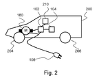
- the charging and driving module 100 is arranged for use in a car 200 as depicted by Figure 2 .
- the car 200 comprises the inverter circuit 102, the battery 104, the plug 108 and the electrical machine 180 for driving a front wheel 204. Alternatively or additionally, also a rear wheel 208 may be driven as well, by the electrical machine 180 or an additional electrical machine.
- the car 200 also comprises a control circuit 210 for driving the inverter circuit 102.
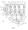
- the inverter circuit 102 comprises a first group comprising a first switch 112 in parallel with a first diode 114, which group is in series with a second group comprising second switch 116 and a second diode 118 in parallel.
- a group of a third switch 122 and a third diode 124 in parallel is provided in series with a group of a further switch 126 and a fourth diode 128 in parallel.
- three pairs of two groups of a switch and a diode connected in parallel are provided, the two groups being connected in series to one another and the pairs are connected in parallel to one another.
- the diodes all have the same orientation.
- the inverter circuit further comprises a capacitor 106 in parallel to the pairs of groups of a switch and a diode and a first DC terminal 152 and a second DC terminal 154 for connecting the battery 104 in parallel to the capacitor.
- a seventh diode 144 and an eight diode 148 connected in series are connected to the inverter circuit 102.
- terminals are provided for connecting the inverter circuit 102 to the electrical machine 180.
- a first phase terminal 162 is provided between the first switch 112 and first diode 114 on one hand and the second switch 116 and the second diode 118 on the other hand.
- a second phase terminal 164 is provided between the third switch 122 and third diode 124 on one hand and the fourth switch 126 and the fourth diode 128 on the other hand.
- a third phase terminal 166 is provided between the fifth switch 132 and fifth diode 134 on one hand and the sixth switch 136 and the sixth diode 138 on the other hand.
- a second charging terminal 172 is provided between the seventh diode 144 and the fourth diode 148.
- a charging plug 108 is connected to the first charging terminal 188 and the second charging terminal 172.
- the switches of the inverter circuit are operated to generate a sine wave at each phase terminal of the inverter circuit 102. This is done by operating the switches in a pulse width modulation (PWM) operation mode.
- PWM pulse width modulation
- the sine waves at the phase terminals are shifted 120° or 2/3 ⁇ .
- the rotating frequency of the electrical machine 180 can be modified. In this way, a DC voltage provided by the battery 104 is converted to a three-phase AC voltage available at the first phase terminal 162, the second phase terminal 164 and the third phase terminal 166.
- the PWM signal may be generated by comparing a sine wave of a target frequency as a reference signal with a saw tooth waveform having a significantly higher frequency, preferably at least ten times as high.
- the output is a binary signal, changing from 0 to 1 on a continuous timescale. This signal is used to drive the first switch 112. The complement of the signal is used to drive the second switch 116.
- a further signal for driving the third switch 122 and the fourth switch 126 is generated by shifting the reference signal by 120° or 2/3 ⁇ , where the fourth switch 126 is driven by the complement of the generated further control signal.
- Another signal for driving the fifth switch 132 is generated by shifting the first reference signal by 240° or 4/3 ⁇ , where the sixth switch 136 is driven by the complement of the generated other control signal. In this way, a fair approximation of a sine wave is generated. Less accurate approximations may also be used, like a block wave or a modified sine wave, but at the cost of efficiency of the electrical machine 180.
- the battery 104 is a rechargeable battery that can be charged by via the plug 108 that is connected to the charging and driving module 100.
- the plug 108 is connected to mains power supply, preferably at 230 Volt at 50 Hz - or 110 Volt at 60 Hz..
- the inverter circuit acts as a full-bridge rectifier.
- the first diode 114, the third diode 124 and the fifth diode 134 are connected in parallel and the second diode 118, the fourth diode 128 and the sixth diode 138 are connected in parallel.
- the three inductances 182, 184, 186 of the electrical machine 180, connected to the phase terminals are connected together and provided with a single phase voltage and all switches are open.
- These groups form one half of the rectifier, equivalent to two diodes in series, with one single phase terminal connected between them.
- Another half of the full-bridge rectifier is provided by the seventh diode 144 and the eighth diode 148.
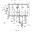
- This circuit equivalent of the configuration is depicted by Figure 3 .
- the full-bridge rectifier is provided by the seventh diode 144 and the eighth diode 148 on one hand and the first diode equivalent 314 and the second diode equivalent 318.
- the first diode equivalent 314 is equivalent to the first diode 114, the third diode 124 and the fifth diode 134 in parallel and the second diode equivalent 318 is equivalent to the second diode 118, the fourth diode 128 and the sixth diode 138 in parallel.
- a single-phase alternating current signal supplied to the plug 108 is converted to a direct current signal, equalised by the capacitor 106 and provided to the battery 104.
- the switches of the inverter circuit are operated simultaneously in the charging phase. Together with the inductances of the electrical machine 180, this constitutes a power factor control circuit for increasing the output voltage over the first DC terminal 152 and the second DC terminal 154.
- the actual output voltage over the first DC terminal 152 and the second DC terminal 154 depends on the duty cycle of the switching of the six switches of the inverter circuit 102.
- the first switch 112 the third switch 122 and the fifth switch 132 are operated simultaneously and that the second switch 116, the fourth switch 126 and the sixth switch 136 are operated simultaneously as well in a charging operation via the plug 108.
- the car 200 should be and remain stationary and the electrical machine 180 is not to rotate to prevent accidents. Therefore, the current through the three inductances should be substantially the same at each moment in time - which is established by operating the switches simultaneously as indicated above.
- An inverter circuit 402 as depicted by Figure 4 comprises a buck converter for converting down the voltage provided by the inverting part of the inverter circuit 402.
- the buck converter comprises a first buck switch 192, a first buck diode 194, a second buck switch 196, a second buck diode 198 and a buck inductor 190.
- a person skilled in the art will appreciate that the first buck diode 194 and the second buck switch 196 are optional and may be omitted.
- the final output voltage provided to the battery 104 is determined by the input voltage, the value of the buck inductor 190 and the duty cycle of the first buck switch 192.
- the charging and driving module 100 may also be used for other vehicles like a bicycle.
- the circuit 102 of the invention can also be used without further amendments when direct voltage is applied over the first charging terminal 188 and the second charging terminal 172 for charging the battery 104.
- the full-bridge rectifier of the invention allows the positive and negative conductors of the direct voltage power supply to be connected to the first charging terminal 188 and second charging terminal 172 in any order.
- the combined inverter and on-board charger may preferably be realised by using an existing inverter control module 210, and merely modifying the software thereof to include a charging mode.
- the other modifications that are required are relatively small hardware modifications, such as adding the first and second rectifying elements 144, 148, the first charging terminal 188 connected to the centre point of the three static inductors 182, 184, 186, and the second charging terminal 172.
- the invention may also be embodied with less components than provided in the embodiments described here, wherein one component carries out multiple functions.
- the invention be embodied using more elements than depicted in the Figures, wherein functions carried out by one component in the embodiment provided are distributed over multiple components.
Landscapes
- Engineering & Computer Science (AREA)
- Power Engineering (AREA)
- Transportation (AREA)
- Mechanical Engineering (AREA)
- Electric Propulsion And Braking For Vehicles (AREA)
- Charge And Discharge Circuits For Batteries Or The Like (AREA)
Abstract
Description
- The invention relates circuits for charging a battery.
-
US patent application 2011/0187185 discloses an electric traction chain for an automobile, including an onboard rechargeable power source, a static converter capable of generating a three-phase voltage system connected by input to the rechargeable power source, a three phase electric motor supplied with power by the three-phase voltage system generated by the static converter, wherein an external electric power source is connectable to the stator windings of the motor to enable recharging of the onboard power source across the static converter. - An issue with this electric traction chain is that it is not very practical for charging by means of a one phase power line in case the electrical machine - the electromotor - comprises permanent magnets in the rotor, because the inductors of the stator are not equally charged. With permanent magnets in the rotor, this causes the rotor to move.
- It is preferred to provide a simple driving and charging circuit with a low number of components.
- A first aspect provides a circuit for charging a battery and for driving a three-phase electrical machine comprising at least three static inductors in Wye configuration having a first charging terminal connected to the centre point. The circuit comprises a three-phase DC to AC converter comprising a plurality of switches and rectifying elements, two DC terminals for connecting the battery to the circuit and three phase terminals for connecting the circuit to the inductors. The circuit further comprises a first rectifying element and a second rectifying element connected in series to one another, with a second charging terminal being provided between the first rectifying element and the second rectifying element. The series of the first rectifying element and the second rectifying element is connected to the DC to AC converter parallel to the DC terminals and the first rectifying element and the second rectifying element have the same orientation as at least two of the rectifying elements of the DC to AC converter as to form a full-bridge rectifier with the rectifying elements of the DC to AC converter for rectifying an alternating voltage applied over the first charging terminal and the second charging terminal to provide a rectified voltage between the two DC terminals.
- Static converters, electrical inverters and other DC to AC converters comprise rectifying elements - and diodes in particular - whether single level or multilevel, comprise rectifying elements like diodes and switches, with the diodes in the same orientation with respect to the DC terminals. By providing two additional diodes in series, with a charging terminal provided between them, a full-bridge rectifier can be created. Half the rectifier is provided by the additional two diodes, the other half is provided by the inverter. This allows charging of a battery by means of an alternating current signal. Numerous topologies are available for DC to AC converters comprising rectifying elements and switches, though all have at least two rectifying elements in series that can be used as one half for a full-bridge rectifier.
- In an embodiment, the DC to AC converter comprises three pairs of two groups of a switch and a rectifying element connected in parallel, the two groups being connected in series to one another with a phase terminal being provided between the two groups and the pairs being connected in parallel to one another and wherein the rectifying elements all have the same orientation.
- Such inverter has a simple and feasible design, with a low component count. The full bridge rectifier is provided by one or more pairs of groups of a switch and a rectifying element connected in parallel as a first half and the two additional rectifying elements as a second half.
- An embodiment further comprises a DC to DC converter for reducing a converter voltage provided by the DC to AC converter to a charging voltage lower than the converter voltage, the input of the DC to DC converter being connected parallel to the DC part of the DC to AC converter and the output of the DC to DC converter being connected to the two DC terminals.
- A second aspect provides a driving and charging module for a vehicle comprising: a three-phase electrical machine comprising at least three inductances in Wye configuration, a connector connected to the first charging terminal and the second charging terminal and any circuit according to the first aspect and embodiments thereof.
- Such module is ready to be assembled in a vehicle. The connector is provided for connecting the module to a one-phase charging source, like a wall socket. In this case, the connector is of the male type. Alternatively, the connector is of the female type for connecting an extension cord. The latter option is also feasible with the connector being of the male type.
- In a third aspect, vehicle is provided comprising: at least two wheels; the module according to the second aspect, a control module for controlling the switches of the circuit; and a battery being connected to the module. In the vehicle, at least one of the two wheels is connected to the three-phase electrical machine for driving the wheel.
- Such vehicle may be a car, a bicycle, a lorry, a toy or other.
- The invention will now be discussed in further detail by means of Figures. In the Figures,
Figure 1 shows:a charging and driving module Figure 2 shows:a vehicle comprising the charging and driving module; Figure 3 shows:an equivalent of the charging and driving module during charging operation; and Figure 4 shows:another charging and driving module. -
Figure 1 shows a charging anddriving module 100 for a vehicle. The charging anddriving module 100 comprises aninverter circuit 102, anelectrical machine 180, abattery 104 and aplug 108. Theinverter circuit 102 arranged for driving theelectrical machine 180 and for charging thebattery 104. - The
electrical machine 180 comprises afirst inductor 182, asecond inductor 184 and athird inductor 186. The three inductors are connected in Wye configuration, with a common centre point at which centre point afirst charging terminal 188 is provided. The three inductors are preferably static inductors, acting as a stator for theelectrical machine 180. The rotor is preferably provided with permanent magnets provided on a shaft. By providing alternating currents through the static inductors, each current having a phase shift of preferably 120° or 2/3 π, the rotor may be driven to establish a rotary movement of the rotor and the shaft. - The charging and
driving module 100 is arranged for use in acar 200 as depicted byFigure 2 . Thecar 200 comprises theinverter circuit 102, thebattery 104, theplug 108 and theelectrical machine 180 for driving afront wheel 204. Alternatively or additionally, also arear wheel 208 may be driven as well, by theelectrical machine 180 or an additional electrical machine. Thecar 200 also comprises acontrol circuit 210 for driving theinverter circuit 102. - The
inverter circuit 102 comprises a first group comprising afirst switch 112 in parallel with afirst diode 114, which group is in series with a second group comprisingsecond switch 116 and asecond diode 118 in parallel. In parallel with the two groups of switches and diodes, a group of athird switch 122 and athird diode 124 in parallel is provided in series with a group of afurther switch 126 and afourth diode 128 in parallel. Also a group of afifth switch 132 and afifth diode 134 in parallel in series with a group of asixth switch 136 and asixth diode 138 in parallel which groups are arranged in series and - in series - are placed parallel with the other groups in series. Hence, three pairs of two groups of a switch and a diode connected in parallel are provided, the two groups being connected in series to one another and the pairs are connected in parallel to one another. The diodes all have the same orientation. - The inverter circuit further comprises a
capacitor 106 in parallel to the pairs of groups of a switch and a diode and afirst DC terminal 152 and asecond DC terminal 154 for connecting thebattery 104 in parallel to the capacitor. In parallel to the capacitor, also aseventh diode 144 and an eightdiode 148 connected in series are connected to theinverter circuit 102. - Between each of the three groups of switches and diodes, terminals are provided for connecting the
inverter circuit 102 to theelectrical machine 180. Between thefirst switch 112 andfirst diode 114 on one hand and thesecond switch 116 and thesecond diode 118 on the other hand, afirst phase terminal 162 is provided. Between thethird switch 122 andthird diode 124 on one hand and thefourth switch 126 and thefourth diode 128 on the other hand, asecond phase terminal 164 is provided. Between thefifth switch 132 andfifth diode 134 on one hand and thesixth switch 136 and thesixth diode 138 on the other hand, athird phase terminal 166 is provided. And between theseventh diode 144 and thefourth diode 148, asecond charging terminal 172 is provided. - A
charging plug 108 is connected to thefirst charging terminal 188 and thesecond charging terminal 172. - For driving the
electrical machine 180, the switches of the inverter circuit are operated to generate a sine wave at each phase terminal of theinverter circuit 102. This is done by operating the switches in a pulse width modulation (PWM) operation mode. The sine waves at the phase terminals are shifted 120° or 2/3 π. By changing the frequency of the sine waves, the rotating frequency of theelectrical machine 180 can be modified. In this way, a DC voltage provided by thebattery 104 is converted to a three-phase AC voltage available at thefirst phase terminal 162, thesecond phase terminal 164 and thethird phase terminal 166. - The PWM signal may be generated by comparing a sine wave of a target frequency as a reference signal with a saw tooth waveform having a significantly higher frequency, preferably at least ten times as high. The output is a binary signal, changing from 0 to 1 on a continuous timescale. This signal is used to drive the
first switch 112. The complement of the signal is used to drive thesecond switch 116. A further signal for driving thethird switch 122 and thefourth switch 126 is generated by shifting the reference signal by 120° or 2/3 π, where thefourth switch 126 is driven by the complement of the generated further control signal. Another signal for driving thefifth switch 132 is generated by shifting the first reference signal by 240° or 4/3 π, where thesixth switch 136 is driven by the complement of the generated other control signal. In this way, a fair approximation of a sine wave is generated. Less accurate approximations may also be used, like a block wave or a modified sine wave, but at the cost of efficiency of theelectrical machine 180. - The
battery 104 is a rechargeable battery that can be charged by via theplug 108 that is connected to the charging and drivingmodule 100. For basic charging operation of theinverter circuit 102 for charging thebattery 104, all switches of theinverter circuit 102 are opened, i.e. in non-conductive state. Theplug 108 is connected to mains power supply, preferably at 230 Volt at 50 Hz - or 110 Volt at 60 Hz.. - In basic charging operation, the inverter circuit, with the three pairs of switch-diode groups, acts as a full-bridge rectifier. The
first diode 114, thethird diode 124 and thefifth diode 134 are connected in parallel and thesecond diode 118, thefourth diode 128 and thesixth diode 138 are connected in parallel. This is because the threeinductances electrical machine 180, connected to the phase terminals, are connected together and provided with a single phase voltage and all switches are open. These groups form one half of the rectifier, equivalent to two diodes in series, with one single phase terminal connected between them. Another half of the full-bridge rectifier is provided by theseventh diode 144 and theeighth diode 148. This circuit equivalent of the configuration is depicted byFigure 3 . - In
Figure 3 , the full-bridge rectifier is provided by theseventh diode 144 and theeighth diode 148 on one hand and the first diode equivalent 314 and thesecond diode equivalent 318. The first diode equivalent 314 is equivalent to thefirst diode 114, thethird diode 124 and thefifth diode 134 in parallel and the second diode equivalent 318 is equivalent to thesecond diode 118, thefourth diode 128 and thesixth diode 138 in parallel. - In this way, a single-phase alternating current signal supplied to the
plug 108 is converted to a direct current signal, equalised by thecapacitor 106 and provided to thebattery 104. - In case the battery requires a voltage higher than the top voltage of the mains power supply, the switches of the inverter circuit are operated simultaneously in the charging phase. Together with the inductances of the
electrical machine 180, this constitutes a power factor control circuit for increasing the output voltage over thefirst DC terminal 152 and thesecond DC terminal 154. The actual output voltage over thefirst DC terminal 152 and thesecond DC terminal 154 depends on the duty cycle of the switching of the six switches of theinverter circuit 102. - It is important that the
first switch 112, thethird switch 122 and thefifth switch 132 are operated simultaneously and that thesecond switch 116, thefourth switch 126 and thesixth switch 136 are operated simultaneously as well in a charging operation via theplug 108. This is because in plug-in charging operation, thecar 200 should be and remain stationary and theelectrical machine 180 is not to rotate to prevent accidents. Therefore, the current through the three inductances should be substantially the same at each moment in time - which is established by operating the switches simultaneously as indicated above. - On the other hand, in case the
batter 104 requires a lower voltage than the top voltage of mains power supply provided to theplug 108, theinverter circuit 102 as shown byFigure 1 is not sufficient. Aninverter circuit 402 as depicted byFigure 4 comprises a buck converter for converting down the voltage provided by the inverting part of theinverter circuit 402. The buck converter comprises afirst buck switch 192, afirst buck diode 194, asecond buck switch 196, asecond buck diode 198 and abuck inductor 190. A person skilled in the art will appreciate that thefirst buck diode 194 and thesecond buck switch 196 are optional and may be omitted. The final output voltage provided to thebattery 104 is determined by the input voltage, the value of thebuck inductor 190 and the duty cycle of thefirst buck switch 192. - A person skilled in the art will appreciate that various variations to the embodiments as provided above are possible. Instead of the diodes, also other rectifying elements may be used, either active or passive. For the switches, any suitable electronic switch may be used, including, but not limited to Triacs, IGBTs, GTOs, MOSFETs and other. As to the
car 200, it is noted that the charging and drivingmodule 100 may also be used for other vehicles like a bicycle. - The
circuit 102 of the invention can also be used without further amendments when direct voltage is applied over thefirst charging terminal 188 and thesecond charging terminal 172 for charging thebattery 104. Moreover, the full-bridge rectifier of the invention allows the positive and negative conductors of the direct voltage power supply to be connected to thefirst charging terminal 188 andsecond charging terminal 172 in any order. - The combined inverter and on-board charger may preferably be realised by using an existing
inverter control module 210, and merely modifying the software thereof to include a charging mode. The other modifications that are required are relatively small hardware modifications, such as adding the first andsecond rectifying elements first charging terminal 188 connected to the centre point of the threestatic inductors second charging terminal 172. - Expressions such as "comprise", "include", "incorporate", "contain", "is" and "have" are to be construed in a non-exclusive manner when interpreting the description and its associated claims, namely construed to allow for other items or components which are not explicitly defined also to be present. Reference to the singular is also to be construed in be a reference to the plural and vice versa.
- In the description above, it will be understood that when an element such as layer, region or substrate is referred to as being "on", "onto" or "connected to" another element, the element is either directly on or connected to the other element, or intervening elements may also be present.
- Furthermore, the invention may also be embodied with less components than provided in the embodiments described here, wherein one component carries out multiple functions. Just as well may the invention be embodied using more elements than depicted in the Figures, wherein functions carried out by one component in the embodiment provided are distributed over multiple components.
- A person skilled in the art will readily appreciate that various parameters disclosed in the description may be modified and that various embodiments disclosed and/or claimed may be combined without departing from the scope of the invention.
- It is stipulated that the reference signs in the claims do not limit the scope of the claims, but are merely inserted to enhance the legibility of the claims.
Claims (7)
- Circuit (102) for charging a battery (104) and for driving a three-phase electrical machine (180) comprising at least three static inductors (182, 184, 186) in wye configuration having a first charging terminal (188) connected to the centre point, the circuit comprising:- a three-phase DC to AC converter comprising:- a plurality of switches (112, 116, 122, 126, 132, 136) and rectifying elements (114, 118, 124, 128, 134, 138);- two DC terminals (152, 154) for connecting the battery (104) to the circuit (102); and- three phase terminals (162, 164, 166) for connecting the circuit (102) to the inductors(182, 184, 186);
characterised in that:- the circuit (102) further comprises a first rectifying element (144) and a second rectifying element (148) connected in series to one another, with a second charging terminal (172) being provided between the first rectifying element (144) and the second rectifying element (148);- the series of the first rectifying element (144) and the second rectifying element (148) is connected to the DC to AC converter parallel to the DC terminals (152, 154); and- the first rectifying element (144) and the second rectifying element (148) have the same orientation as at least two of the rectifying elements (114, 118, 124, 128, 134, 138) of the DC to AC converter as to form a full-bridge rectifier with the rectifying elements (114, 118, 124, 128, 134, 138) of the DC to AC converter for rectifying an alternating voltage applied over the first charging terminal (188) and the second charging terminal (172) to provide a rectified voltage between the two DC terminals (152, 154). - Circuit according to claim 1, wherein the DC to AC converter comprises three pairs of two groups of a switch (112, 116, 122, 126, 132, 136) and a rectifying element (114, 118, 124, 128, 134, 138) connected in parallel, the two groups being connected in series to one another with a phase terminal (162, 164, 166) being provided between the two groups and the pairs being connected in parallel to one another and wherein the rectifying elements (114, 118, 124, 128, 134, 138) all have the same orientation.
- Circuit (102) according to any of the preceding claims comprising a capacitance (106) being connected parallel to the DC to AC converter.
- Circuit (102) according to any of the preceding claims, further comprising a DC to DC converter for reducing a converter voltage provided by the DC to AC converter to a charging voltage lower than the converter voltage, the input of the DC to DC converter being connected parallel to the DC part of the DC to AC converter and the output of the DC to DC converter being connected to the two DC terminals.
- Circuit according to claim 4, wherein the DC to DC converter is a buck converter.
- Driving and charging module (100) for a vehicle comprising:- a three-phase electrical machine (180) comprising at least three inductances (182, 184, 186) in Wye configuration;- a connector (108) connected to the first charging terminal (188) and the second charging terminal (172);- a circuit (102) according to any of the claim 1 to 5.
- Vehicle (200) comprising:- at least two wheels(204, 208);- the module (100) according to claim 6;- a control module (210) for controlling the switches (112, 116, 122, 126, 132, 136, 192, 196) of the circuit (102); and- a battery (104) being connected to the module (100);wherein at least one of the two wheels (204, 208) is connected to the three-phase electrical machine (180) for driving the wheel (204, 208).
Priority Applications (3)
| Application Number | Priority Date | Filing Date | Title |
|---|---|---|---|
| EP12163125.3A EP2647523A1 (en) | 2012-04-04 | 2012-04-04 | Circuit for charging a battery and for driving a three-phase electrical machine |
| CN201310052657.8A CN103368239B (en) | 2012-04-04 | 2013-02-18 | For the circuit that drives three phase electric machine of charging and be used for battery |
| US13/796,331 US9387769B2 (en) | 2012-04-04 | 2013-03-12 | Circuit for charging a battery and for driving a three-phase electrical machine |
Applications Claiming Priority (1)
| Application Number | Priority Date | Filing Date | Title |
|---|---|---|---|
| EP12163125.3A EP2647523A1 (en) | 2012-04-04 | 2012-04-04 | Circuit for charging a battery and for driving a three-phase electrical machine |
Publications (1)
| Publication Number | Publication Date |
|---|---|
| EP2647523A1 true EP2647523A1 (en) | 2013-10-09 |
Family
ID=45976755
Family Applications (1)
| Application Number | Title | Priority Date | Filing Date |
|---|---|---|---|
| EP12163125.3A Withdrawn EP2647523A1 (en) | 2012-04-04 | 2012-04-04 | Circuit for charging a battery and for driving a three-phase electrical machine |
Country Status (3)
| Country | Link |
|---|---|
| US (1) | US9387769B2 (en) |
| EP (1) | EP2647523A1 (en) |
| CN (1) | CN103368239B (en) |
Cited By (2)
| Publication number | Priority date | Publication date | Assignee | Title |
|---|---|---|---|---|
| WO2018033376A1 (en) * | 2016-08-17 | 2018-02-22 | Continental Automotive Gmbh | On-board vehicle electrical system, motor vehicle and method |
| WO2025227592A1 (en) * | 2024-04-28 | 2025-11-06 | 东风汽车集团股份有限公司 | Electric-vehicle charging circuit and apparatus |
Families Citing this family (8)
| Publication number | Priority date | Publication date | Assignee | Title |
|---|---|---|---|---|
| DE102010061763B4 (en) * | 2010-11-23 | 2024-09-12 | Robert Bosch Gmbh | battery |
| WO2016011656A1 (en) * | 2014-07-25 | 2016-01-28 | 中山大洋电机股份有限公司 | Drive and charging integrated control method for electric vehicle, and electric vehicle using same |
| US20160094080A1 (en) * | 2014-09-29 | 2016-03-31 | Chervon Intellectual Property Limited | Charging system and charging method thereof and battery pack |
| DE102015102517B4 (en) * | 2015-02-23 | 2025-07-03 | Dr. Ing. H.C. F. Porsche Aktiengesellschaft | Vehicle with a charging system for a battery |
| CN105490364A (en) * | 2015-12-31 | 2016-04-13 | 华域汽车电动系统有限公司 | Integrated vehicle-mounted charger and automobile using same |
| CN106740152A (en) * | 2016-11-06 | 2017-05-31 | 华北电力大学 | A kind of electric automobile uses the vehicle-mounted integrated form charge-discharge circuit of shunting tap |
| CN111038300A (en) * | 2018-10-15 | 2020-04-21 | 乐金电子研发中心(上海)有限公司 | Vehicle-mounted power electronic integrated device |
| EP4082822A1 (en) * | 2021-04-29 | 2022-11-02 | Volvo Truck Corporation | A motor drive, a method and a control unit for handling connection between a motor drive and a tvs in an at least partly electrically operated vehicle |
Citations (4)
| Publication number | Priority date | Publication date | Assignee | Title |
|---|---|---|---|---|
| JP2000354331A (en) * | 1999-06-09 | 2000-12-19 | Toyota Motor Corp | Charging device |
| EP2116405A1 (en) * | 2007-01-04 | 2009-11-11 | Toyota Jidosha Kabushiki Kaisha | Hybrid vehicle and vehicle |
| US20110187185A1 (en) | 2008-07-28 | 2011-08-04 | Renault S.A.S. | Electric traction chain for an automobile |
| WO2012035832A1 (en) * | 2010-09-14 | 2012-03-22 | ヤンマー株式会社 | Electric work machine |
Family Cites Families (2)
| Publication number | Priority date | Publication date | Assignee | Title |
|---|---|---|---|---|
| US6160722A (en) * | 1999-08-13 | 2000-12-12 | Powerware Corporation | Uninterruptible power supplies with dual-sourcing capability and methods of operation thereof |
| JP5348330B2 (en) * | 2011-09-21 | 2013-11-20 | トヨタ自動車株式会社 | Electric vehicle charging system and charging control method |
-
2012
- 2012-04-04 EP EP12163125.3A patent/EP2647523A1/en not_active Withdrawn
-
2013
- 2013-02-18 CN CN201310052657.8A patent/CN103368239B/en active Active
- 2013-03-12 US US13/796,331 patent/US9387769B2/en active Active
Patent Citations (4)
| Publication number | Priority date | Publication date | Assignee | Title |
|---|---|---|---|---|
| JP2000354331A (en) * | 1999-06-09 | 2000-12-19 | Toyota Motor Corp | Charging device |
| EP2116405A1 (en) * | 2007-01-04 | 2009-11-11 | Toyota Jidosha Kabushiki Kaisha | Hybrid vehicle and vehicle |
| US20110187185A1 (en) | 2008-07-28 | 2011-08-04 | Renault S.A.S. | Electric traction chain for an automobile |
| WO2012035832A1 (en) * | 2010-09-14 | 2012-03-22 | ヤンマー株式会社 | Electric work machine |
Cited By (2)
| Publication number | Priority date | Publication date | Assignee | Title |
|---|---|---|---|---|
| WO2018033376A1 (en) * | 2016-08-17 | 2018-02-22 | Continental Automotive Gmbh | On-board vehicle electrical system, motor vehicle and method |
| WO2025227592A1 (en) * | 2024-04-28 | 2025-11-06 | 东风汽车集团股份有限公司 | Electric-vehicle charging circuit and apparatus |
Also Published As
| Publication number | Publication date |
|---|---|
| US9387769B2 (en) | 2016-07-12 |
| US20130265011A1 (en) | 2013-10-10 |
| CN103368239B (en) | 2017-12-19 |
| CN103368239A (en) | 2013-10-23 |
Similar Documents
| Publication | Publication Date | Title |
|---|---|---|
| US9387769B2 (en) | Circuit for charging a battery and for driving a three-phase electrical machine | |
| US11799292B2 (en) | On-board bidirectional AC fast charger for electric vehicles | |
| US11482948B2 (en) | Systems and methods for an on-board fast charger | |
| CN103931093B (en) | Device and method for charging traction battery of electric or hybrid vehicle | |
| KR101387717B1 (en) | Battery charger and electric vehicle having the same | |
| CN102593928A (en) | Method and apparatus for generating a charging circuit | |
| EP2605396B1 (en) | A track-bound vehicle inverter | |
| CN101325381B (en) | Two-source inverter | |
| CN102195330A (en) | Battery charging circuit and charging method | |
| KR20100044723A (en) | Traction inverter circuit | |
| JP6636905B2 (en) | Power converter | |
| Ketsingsoi et al. | An off-line battery charger based on buck-boost power factor correction converter for plug-in electric vehicles | |
| CN102308471B (en) | Drive system, method for operating a drive system, and use thereof | |
| Subotic et al. | Multiphase integrated on-board battery chargers for electrical vehicles | |
| CN110461641B (en) | Charging circuit arrangement for a vehicle and method for a charging circuit arrangement | |
| US20140103650A1 (en) | Dual-dc bus starter/generator | |
| WO2011004588A1 (en) | Electric vehicle control device | |
| EP4338274A1 (en) | Dynamically reconfigurable power converter utilizing windings of electrical machine | |
| JP2016220345A (en) | Power conversion device for vehicle | |
| WO2011089563A2 (en) | A switching device | |
| JP5724830B2 (en) | Power system | |
| Tenner et al. | Loss minimization of electric drive systems using a Z-source inverter in automotive applications | |
| JP5755583B2 (en) | Power control system | |
| Kumar et al. | A magnetically coupled converter connected three phase voltage source inverter for EV applications | |
| CN117944475B (en) | System and method for controlling a multi-function electric powertrain |
Legal Events
| Date | Code | Title | Description |
|---|---|---|---|
| PUAI | Public reference made under article 153(3) epc to a published international application that has entered the european phase |
Free format text: ORIGINAL CODE: 0009012 |
|
| AK | Designated contracting states |
Kind code of ref document: A1 Designated state(s): AL AT BE BG CH CY CZ DE DK EE ES FI FR GB GR HR HU IE IS IT LI LT LU LV MC MK MT NL NO PL PT RO RS SE SI SK SM TR |
|
| AX | Request for extension of the european patent |
Extension state: BA ME |
|
| 17P | Request for examination filed |
Effective date: 20140409 |
|
| RBV | Designated contracting states (corrected) |
Designated state(s): AL AT BE BG CH CY CZ DE DK EE ES FI FR GB GR HR HU IE IS IT LI LT LU LV MC MK MT NL NO PL PT RO RS SE SI SK SM TR |
|
| 17Q | First examination report despatched |
Effective date: 20180111 |
|
| STAA | Information on the status of an ep patent application or granted ep patent |
Free format text: STATUS: THE APPLICATION IS DEEMED TO BE WITHDRAWN |
|
| 18D | Application deemed to be withdrawn |
Effective date: 20180523 |