EP2647513A1 - Air conditioning circuit duct provided with a noise reducing device, and circuit including it - Google Patents
Air conditioning circuit duct provided with a noise reducing device, and circuit including it Download PDFInfo
- Publication number
- EP2647513A1 EP2647513A1 EP20130161856 EP13161856A EP2647513A1 EP 2647513 A1 EP2647513 A1 EP 2647513A1 EP 20130161856 EP20130161856 EP 20130161856 EP 13161856 A EP13161856 A EP 13161856A EP 2647513 A1 EP2647513 A1 EP 2647513A1
- Authority
- EP
- European Patent Office
- Prior art keywords
- pipe
- male
- axially
- female
- air conditioning
- Prior art date
- Legal status (The legal status is an assumption and is not a legal conclusion. Google has not performed a legal analysis and makes no representation as to the accuracy of the status listed.)
- Granted
Links
- 238000004378 air conditioning Methods 0.000 title claims description 31
- 239000012530 fluid Substances 0.000 claims abstract description 26
- 239000003507 refrigerant Substances 0.000 claims description 17
- 238000002788 crimping Methods 0.000 claims description 5
- 239000003638 chemical reducing agent Substances 0.000 abstract 1
- CURLTUGMZLYLDI-UHFFFAOYSA-N Carbon dioxide Chemical compound O=C=O CURLTUGMZLYLDI-UHFFFAOYSA-N 0.000 description 6
- 239000000463 material Substances 0.000 description 5
- 238000011144 upstream manufacturing Methods 0.000 description 4
- 240000008042 Zea mays Species 0.000 description 3
- 229910002092 carbon dioxide Inorganic materials 0.000 description 3
- 239000001569 carbon dioxide Substances 0.000 description 3
- 239000007788 liquid Substances 0.000 description 3
- 238000004519 manufacturing process Methods 0.000 description 3
- 230000001902 propagating effect Effects 0.000 description 3
- 239000004952 Polyamide Substances 0.000 description 2
- 230000004323 axial length Effects 0.000 description 2
- 230000005540 biological transmission Effects 0.000 description 2
- 230000000694 effects Effects 0.000 description 2
- 239000002184 metal Substances 0.000 description 2
- 239000004033 plastic Substances 0.000 description 2
- 229920002647 polyamide Polymers 0.000 description 2
- 230000002238 attenuated effect Effects 0.000 description 1
- 239000002274 desiccant Substances 0.000 description 1
- 235000021183 entrée Nutrition 0.000 description 1
- 238000009499 grossing Methods 0.000 description 1
- 238000009434 installation Methods 0.000 description 1
- 230000004048 modification Effects 0.000 description 1
- 238000012986 modification Methods 0.000 description 1
- 230000000149 penetrating effect Effects 0.000 description 1
- 230000003014 reinforcing effect Effects 0.000 description 1
Images


Classifications
-
- F—MECHANICAL ENGINEERING; LIGHTING; HEATING; WEAPONS; BLASTING
- F24—HEATING; RANGES; VENTILATING
- F24F—AIR-CONDITIONING; AIR-HUMIDIFICATION; VENTILATION; USE OF AIR CURRENTS FOR SCREENING
- F24F13/00—Details common to, or for air-conditioning, air-humidification, ventilation or use of air currents for screening
- F24F13/02—Ducting arrangements
-
- F—MECHANICAL ENGINEERING; LIGHTING; HEATING; WEAPONS; BLASTING
- F16—ENGINEERING ELEMENTS AND UNITS; GENERAL MEASURES FOR PRODUCING AND MAINTAINING EFFECTIVE FUNCTIONING OF MACHINES OR INSTALLATIONS; THERMAL INSULATION IN GENERAL
- F16L—PIPES; JOINTS OR FITTINGS FOR PIPES; SUPPORTS FOR PIPES, CABLES OR PROTECTIVE TUBING; MEANS FOR THERMAL INSULATION IN GENERAL
- F16L55/00—Devices or appurtenances for use in, or in connection with, pipes or pipe systems
- F16L55/02—Energy absorbers; Noise absorbers
- F16L55/033—Noise absorbers
-
- B—PERFORMING OPERATIONS; TRANSPORTING
- B60—VEHICLES IN GENERAL
- B60H—ARRANGEMENTS OF HEATING, COOLING, VENTILATING OR OTHER AIR-TREATING DEVICES SPECIALLY ADAPTED FOR PASSENGER OR GOODS SPACES OF VEHICLES
- B60H1/00—Heating, cooling or ventilating [HVAC] devices
-
- B—PERFORMING OPERATIONS; TRANSPORTING
- B60—VEHICLES IN GENERAL
- B60H—ARRANGEMENTS OF HEATING, COOLING, VENTILATING OR OTHER AIR-TREATING DEVICES SPECIALLY ADAPTED FOR PASSENGER OR GOODS SPACES OF VEHICLES
- B60H1/00—Heating, cooling or ventilating [HVAC] devices
- B60H1/00507—Details, e.g. mounting arrangements, desaeration devices
- B60H1/00557—Details of ducts or cables
- B60H1/00571—Details of ducts or cables of liquid ducts, e.g. for coolant liquids or refrigerants
-
- F—MECHANICAL ENGINEERING; LIGHTING; HEATING; WEAPONS; BLASTING
- F16—ENGINEERING ELEMENTS AND UNITS; GENERAL MEASURES FOR PRODUCING AND MAINTAINING EFFECTIVE FUNCTIONING OF MACHINES OR INSTALLATIONS; THERMAL INSULATION IN GENERAL
- F16L—PIPES; JOINTS OR FITTINGS FOR PIPES; SUPPORTS FOR PIPES, CABLES OR PROTECTIVE TUBING; MEANS FOR THERMAL INSULATION IN GENERAL
- F16L21/00—Joints with sleeve or socket
- F16L21/08—Joints with sleeve or socket with additional locking means
-
- B—PERFORMING OPERATIONS; TRANSPORTING
- B60—VEHICLES IN GENERAL
- B60H—ARRANGEMENTS OF HEATING, COOLING, VENTILATING OR OTHER AIR-TREATING DEVICES SPECIALLY ADAPTED FOR PASSENGER OR GOODS SPACES OF VEHICLES
- B60H1/00—Heating, cooling or ventilating [HVAC] devices
- B60H1/00507—Details, e.g. mounting arrangements, desaeration devices
- B60H2001/006—Noise reduction
Landscapes
- Engineering & Computer Science (AREA)
- General Engineering & Computer Science (AREA)
- Mechanical Engineering (AREA)
- Physics & Mathematics (AREA)
- Thermal Sciences (AREA)
- Chemical & Material Sciences (AREA)
- Combustion & Propulsion (AREA)
- Pipe Accessories (AREA)
- Air-Conditioning For Vehicles (AREA)
- Duct Arrangements (AREA)
- Quick-Acting Or Multi-Walled Pipe Joints (AREA)
Abstract
Description
La présente invention concerne une canalisation pour fluide sous pression pour un circuit de climatisation d'un véhicule automobile ou d'un bâtiment (i.e. climatisation industrielle, par exemple), la canalisation comprenant une conduite comportant un embout mâle qui contient un dispositif réducteur de bruit et un embout femelle connecté de manière étanche à l'embout mâle, et un tel circuit de climatisation incorporant cette canalisation.The present invention relates to a duct for pressurized fluid for an air conditioning circuit of a motor vehicle or a building (ie industrial air conditioning, for example), the duct comprising a pipe comprising a spigot end which contains a noise reducing device. and a female connector sealingly connected to the male end, and such an air conditioning circuit incorporating this pipe.
D'une manière générale, un dispositif réducteur de bruit pour circuit de climatisation d'un véhicule automobile est formé d'une capacité acoustique qui est montée en ligne dans une canalisation de ce circuit entre un compresseur et un évaporateur, de sorte à atténuer la transmission des ondes sonores générées principalement par le compresseur et se propageant dans le fluide frigorigène à l'intérieur de la conduite, via un élargissement brusque de la section de passage du fluide pénétrant dans cette capacité. En effet, cet élargissement de la section de passage à l'entrée dans la capacité se traduit de manière connue par la création d'une onde sonore en opposition de phase s'additionnant à l'onde perturbatrice pour générer une onde atténuée d'amplitude plus réduite.In general, a noise reduction device for an air conditioning circuit of a motor vehicle is formed of an acoustic capacitance which is mounted in line in a pipe of this circuit between a compressor and an evaporator, so as to attenuate the transmission of the sound waves generated mainly by the compressor and propagating in the refrigerant inside the pipe, via a sudden enlargement of the passage section of the fluid penetrating into this capacity. Indeed, this widening of the passage section at the entry into the capacitance is translated in known manner by the creation of a sound wave in opposition of phase adding to the disturbing wave to generate an attenuated wave of amplitude more reduced.
Une telle capacité acoustique est usuellement située à un emplacement de la canalisation du circuit de climatisation qui est relativement éloigné du compresseur, essentiellement à cause du volume qu'occupe cette capacité et de la place qui fait souvent défaut dans le groupe motopropulseur du véhicule automobile comprenant ce compresseur, pour installer la capacité à proximité immédiate de ce dernier et, dans les cas où cette installation de la capacité à proximité immédiate du compresseur serait néanmoins envisageable, à cause des vibrations mécaniques indésirables qui sont générées par la présence de la masse additionnelle formée par cette capacité et qui peuvent être une source de rupture de la canalisation correspondante.Such acoustic capacity is usually located at a location of the air conditioning circuit duct which is relatively remote from the compressor, essentially because of the volume occupied by this capacity and the space that is often lacking in the powertrain of the motor vehicle comprising this compressor, to install the capacity in the immediate vicinity of the latter and, in cases where this installation of the capacity in the immediate vicinity of the compressor would nevertheless be possible, because of the undesirable mechanical vibrations which are generated by the presence of the additional mass formed by this capacity and which can be a source of rupture of the corresponding pipeline.
Cet éloignement relatif de la capacité acoustique vis-à-vis du compresseur a notamment pour effet de générer une zone de résonance entre ces deux éléments, dans laquelle le bruit peut s'autoalimenter. Il en résulte que l'atténuation du bruit dans la canalisation du circuit de climatisation est encore perfectible.This relative distance of the acoustic capacitance vis-à-vis the compressor has the effect of generating a resonance zone between these two elements, in which the noise can self-feed. As a result, the attenuation of noise in the duct of the air conditioning circuit is still perfectible.
Ces capacités acoustiques permettent ainsi d'atténuer dans une certaine mesure le bruit généré par le compresseur et se propageant dans la canalisation du circuit de climatisation. Cependant, elles présentent en même temps l'inconvénient de générer des pertes de charge significatives pour le fluide les traversant, du fait de la modification brusque de la section de passage qui les caractérise. En outre, elles présentent un coût de fabrication et d'implantation sur la canalisation du circuit de climatisation qui est relativement élevé.These acoustic capabilities thus make it possible to mitigate to a certain extent the noise generated by the compressor and propagating in the pipe of the air conditioning circuit. However, they present at the same time the disadvantage of generating significant pressure drops for the fluid passing through them, due to the abrupt modification of the passage section which characterizes them. In addition, they have a manufacturing cost and implementation on the pipe of the air conditioning circuit is relatively high.
Le document
Le document
Un but de la présente invention est de proposer une nouvelle structure de canalisation pour fluide sous pression de type gazeux ou supercritique d'un circuit de climatisation d'un véhicule automobile ou d'un bâtiment, de type à embout mâle intégrant un dispositif réducteur de bruit pouvant être du type décrit dans les documents précités
- une conduite comportant un embout tubulaire mâle de diamètre interne nominal D0 et un embout tubulaire femelle qui est connecté de manière étanche à l'embout mâle en une portion axiale élargie de l'embout femelle ou bien à proximité immédiate d'une portion axiale élargie de l'embout mâle, cette portion élargie d'embout mâle ou femelle présentant un diamètre interne maximal D2 et l'embout femelle présentant un diamètre interne nominal D0' identique ou non à D0, et
- un dispositif réducteur de bruit globalement tubulaire qui est monté axialement et radialement à l'intérieur de l'embout mâle et qui définit, entre deux extrémités axialement interne et externe de ce dispositif par rapport à l'embout mâle (par « interne » et « externe », on entend ici les extrémités du dispositif respectivement tournées axialement vers l'intérieur de l'embout mâle à l'opposé de l'embout femelle et axialement vers l'extérieur de cet embout mâle vers l'embout femelle), au moins un canal de passage du fluide dans la direction de l'axe de la conduite, l'extrémité externe du dispositif étant montée de manière étanche contre un bord terminal de l'embout mâle au droit de l'embout femelle.
- a pipe comprising a male tubular tip of nominal internal diameter D0 and a female tubular nozzle which is sealingly connected to the male end in an enlarged axial portion of the socket or in the immediate vicinity of an enlarged axial portion of the male end, this enlarged portion of male or female endpiece having a maximum internal diameter D2 and the endpiece having a nominal internal diameter D0 'identical or not to D0, and
- a generally tubular noise reducing device which is mounted axially and radially inside the male end and which defines, between two axially inner and outer ends of this device with respect to the male end (by "internal" and " external "means here the ends of the device respectively turned axially towards the inside of the male end opposite the female end and axially towards the outside of this male end towards the female end), at least a fluid passage channel in the direction of the axis of the pipe, the outer end of the device being sealingly mounted against an end edge of the male end to the right of the female end.
A cet effet, la canalisation de l'invention est telle que ladite portion élargie de l'embout mâle ou femelle présente respectivement, à partir de ladite extrémité axialement interne ou externe du dispositif située au droit de cette portion élargie, une longueur L2 telle que L2 ≥ 0,6 . D, où dans ce produit D désigne la valeur commune ou minimale parmi D0 et D0' (i.e. D = D0 = D0' ou bien D = min(D0 ; D0')).For this purpose, the pipe of the invention is such that said enlarged portion of the male or female end respectively has, from said axially internal or external end of the device located at the right of this enlarged portion, a length L 2 such that L2 ≥ 0.6. D, where in this product D denotes the common or minimum value among D0 and D0 '(ie D = D0 = D0' or else D = min (D0; D0 ')).
On notera que cette valeur anormalement élevée utilisée pour cette longueur L2 permet, compte tenu du diamètre interne minimal D1 du dispositif réducteur de bruit qui définit une section de passage relativement réduite pour le fluide et du ratio D2 / D1 (supérieur à 1) entre ce dispositif et la portion élargie de l'embout mâle ou femelle, de positionner la valeur de rupture d'impédance dans le même ordre de grandeur que celui d'une capacité acoustique et ainsi d'obtenir avantageusement une efficacité acoustique améliorée sans modification du diamètre nominal D de la conduite ni du diamètre D2 de la portion élargie de l'embout mâle ou femelle.It will be noted that this abnormally high value used for this length L2 makes it possible, taking into account the minimum internal diameter D1 of the noise reduction device which defines a relatively small passage section for the fluid and the ratio D2 / D1 (greater than 1) between this device and the enlarged portion of the male or female end, to position the impedance break value in the same order of magnitude as that of an acoustic capacitance and thus advantageously to obtain an improved acoustic efficiency without changing the nominal diameter D of the pipe and the diameter D2 of the enlarged portion of the male or female endpiece.
De préférence en relation avec un circuit de climatisation spécifiquement de véhicule automobile, ladite longueur L2 de ladite portion axiale élargie peut être telle que L2 ≥ 10 mm.Preferably in connection with an air conditioning circuit specifically for a motor vehicle, said length L2 of said enlarged axial portion may be such that L2 ≥ 10 mm.
Il convient de noter que cette longueur L2 pour la portion élargie d'embout mâle ou femelle, qui est ainsi supérieure au demi-diamètre 0,5 . D (ou rayon nominal de la conduite) est très élevée notamment en comparaison des longueurs L2 existantes pour les embouts femelles standards utilisés dans ces circuits de climatisation, mesurées entre le bord terminal de l'embout mâle et la naissance de cette portion élargie, lesquelles sont toujours très faibles en étant usuellement comprises entre 0 mm et 1 mm seulement. En effet, jamais à ce jour n'ont été fabriqués dans l'industrie de tels embouts mâles ou femelles avec cette « sur-longueur » L2 d'une dizaine de mm pour la portion élargie, avec notamment comme motifs dissuasifs pour les industriels le coût et la durée de fabrication accrus par rapport à ces embouts mâles ou femelles standards dus à l'utilisation d'un outillage supplémentaire.It should be noted that this length L2 for the enlarged portion of the male or female endpiece, which is thus greater than the half-diameter 0.5. D (or nominal radius of the pipe) is very high, especially in comparison with the existing L2 lengths for the standard female ends used in these air conditioning circuits, measured between the terminal edge of the male end and the birth of this enlarged portion, which are always very low usually between 0 mm and 1 mm only. Indeed, never to date have been manufactured in the industry of such male or female end caps with this "over-length" L2 of about ten mm for the enlarged portion, with particular as deterrent to the industrialists. cost and manufacturing time increased compared to these standard male or female tips due to the use of additional tools.
Encore plus avantageusement, ladite longueur L2 de cette portion axiale élargie peut être telle que 1,5 . D ≤ L2 ≤ 2,4 . D.Even more advantageously, said length L2 of this enlarged axial portion may be such that 1.5. D ≤ L2 ≤ 2.4. D.
Dans ce cas, ladite longueur L2 de cette portion axiale élargie peut être telle que 25 mm ≤ L2 ≤ 40 mm, de préférence pour un circuit de climatisation de véhicule automobile.In this case, said length L2 of this enlarged axial portion may be such that 25 mm ≤ L2 ≤ 40 mm, preferably for a motor vehicle air conditioning circuit.
Selon un premier mode de réalisation de l'invention, l'embout femelle présente une zone terminale de raccordement comprenant ladite portion axiale élargie qui présente une géométrie globalement cylindrique de longueur supérieure à ladite longueur L2 pour le montage étanche d'un tronçon terminal de cette portion élargie radialement sur un tronçon d'extrémité de l'embout mâle, via deux brides annulaires enserrant ces deux tronçons et incluses dans la canalisation, cette portion élargie se prolongeant à l'opposé de l'embout mâle via une portion de liaison convergente par une autre portion globalement cylindrique présentant ledit diamètre interne nominal D0'.According to a first embodiment of the invention, the socket has an end terminal area comprising said enlarged axial portion which has a generally cylindrical geometry of greater length than said length L2 for sealingly mounting a terminal portion of this radially enlarged portion on an end section of the male end, via two annular flanges enclosing these two sections and included in the pipe, this enlarged portion extending away from the male end via a converging connecting portion by another generally cylindrical portion having said nominal internal diameter D0 '.
Selon un second mode de réalisation de l'invention, l'embout mâle présente axialement au-delà de l'embout femelle ladite portion axiale élargie, laquelle présente une géométrie globalement cylindrique de longueur supérieure à ladite longueur L2, l'embout femelle présentant une zone terminale de raccordement montée de manière étanche sur un tronçon d'extrémité de l'embout mâle situé en deçà de cette portion élargie via un organe annulaire de sertissage qui enserre cette zone et qui coopère en butée avec ce tronçon d'extrémité de manière étanche, cette portion élargie se prolongeant en ses deux extrémités par deux tronçons respectifs convergents dont l'un opposé à l'embout femelle définit ledit diamètre interne nominal D0 et l'autre se prolonge par ledit tronçon d'extrémité.According to a second embodiment of the invention, the male endpiece has axially beyond the female end said enlarged axial portion, which has a generally cylindrical geometry longer than said length L2, the female end having a end terminal area sealingly mounted on an end section of the male end located below this enlarged portion via an annular crimping member which encloses this area and which cooperates in abutment with this end portion sealingly this enlarged portion extending at its two ends by two respective convergent sections, one opposite the female end defines said nominal internal diameter D0 and the other is extended by said end section.
Selon une autre caractéristique de l'invention, ladite extrémité axialement externe du dispositif réducteur de bruit peut comporter une collerette radiale montée contre un renflement d'extrémité de l'embout mâle définissant ledit bord terminal de ce dernier.According to another characteristic of the invention, said axially outer end of the noise reducing device may comprise a radial flange mounted against an end bulge of the male end defining said terminal edge of the latter.
Selon un exemple de réalisation de l'invention, le dispositif réducteur de bruit délimite avec l'embout mâle, axialement entre lesdites extrémités axialement interne et externe du dispositif, au moins un volume mort annulaire qui ne communique pas avec ledit canal par l'une au moins de ces deux extrémités. On pourra se reporter au document précité
En particulier et conformément à ce premier exemple, ladite extrémité axialement interne du dispositif peut être également montée de manière étanche contre l'embout mâle, de telle sorte que ledit volume mort annulaire s'étende de ladite extrémité axialement interne à ladite extrémité axialement externe en ne communiquant pas avec ledit canal (voir la
En variante, cette extrémité axialement interne peut former avec l'embout mâle au moins une zone d'admission continue ou discontinue pour le fluide qui est localisée radialement entre cette extrémité axialement interne et l'embout mâle et qui communique avec ledit volume mort annulaire (voir les
Egalement selon cet exemple de réalisation définissant ledit ou chaque volume mort annulaire, ce dispositif réducteur de bruit peut avoir son extrémité axialement interne qui converge vers un tronçon intermédiaire sensiblement cylindrique ou prismatique du dispositif relié à ladite extrémité axialement externe par un tronçon aval divergent, comme illustré par exemple dans ce document
Selon un autre exemple de réalisation de l'invention, le dispositif réducteur de bruit présente une face externe au moins en partie cylindrique qui épouse la face radialement interne de l'embout mâle, comme par exemple illustré dans l'autre document précité
On notera toutefois que d'autres géométries que celles présentées dans ces deux documents sont utilisables pour le dispositif réducteur de bruit d'une canalisation selon l'invention, l'essentiel étant que ce dispositif soit monté de manière étanche contre le bord terminal de l'embout mâle au droit de l'embout femelle.It will be noted, however, that other geometries than those presented in these two documents can be used for the noise-reducing device of a pipe according to the invention, the essential being that this device is sealingly mounted against the terminal edge of the male end to the right of the female end.
Avantageusement, ce dispositif peut être entièrement réalisé en un matériau rigide, tel qu'un métal auquel cas l'épaisseur de sa paroi est de l'ordre de 0,1 mm, ou tel qu'une matière plastique par exemple du polyamide 6.6 auquel cas l'épaisseur de sa paroi est de l'ordre de 1 mm.Advantageously, this device may be entirely made of a rigid material, such as a metal in which case the thickness of its wall is of the order of 0.1 mm, or such as a plastic material for example polyamide 6.6 to which case the thickness of its wall is of the order of 1 mm.
Il convient de noter que ce dispositif globalement tubulaire qui est reçu dans l'embout mâle présente une structure qui permet de l'insérer à une extrémité de la canalisation située à proximité immédiate du compresseur, de sorte que l'atténuation acoustique s'en trouve améliorée contrairement aux capacités acoustiques de l'art antérieur que l'on monte usuellement à distance du compresseur pour les raisons exposées ci-dessus.It should be noted that this generally tubular device that is received in the male end has a structure that allows it to be inserted at one end of the pipe located in the immediate vicinity of the compressor, so that the acoustic attenuation is found improved in contrast to the acoustic capabilities of the prior art that is usually mounted away from the compressor for the reasons explained above.
Un circuit de climatisation selon l'invention d'un véhicule automobile ou d'un bâtiment est du type comportant des canalisations destinées à véhiculer un fluide frigorigène gazeux sous pression et au moins un dispositif réducteur de bruit inséré dans au moins l'une de ces canalisations, cette canalisation contenant ce dispositif étant telle que définie ci-dessus en relation avec la présente invention.An air conditioning circuit according to the invention of a motor vehicle or a building is of the type comprising pipes intended to convey a gaseous refrigerant under pressure and at least one noise reducing device inserted into at least one of these pipes, this pipe containing this device being as defined above in connection with the present invention.
Selon une autre caractéristique avantageuse de l'invention spécifique à un circuit de climatisation pour véhicule automobile, la ou chaque canalisation dans laquelle est inséré ledit au moins un dispositif peut être raccordée directement à l'aspiration (i.e. l'entrée) et/ou au refoulement (i.e. la sortie) dudit compresseur, respectivement dans une ligne basse pression et/ou dans une ligne haute pression dudit circuit, et ce dispositif peut être avantageusement monté à l'extrémité de cette canalisation qui débouche sur ladite aspiration et/ou sur ledit refoulement du compresseur, respectivement dans ladite ligne basse pression et/ou dans ladite ligne haute pression. En d'autres termes, on notera que ce dispositif est utilisable tant dans une ligne basse pression que dans une ligne haute pression d'un tel circuit de climatisation.According to another advantageous characteristic of the invention specific to an air conditioning circuit for a motor vehicle, the or each pipe in which said at least one device is inserted can be connected directly to the suction (ie the inlet) and / or the discharge (ie the output) of said compressor, respectively in a low pressure line and / or in a high pressure line of said circuit, and this device can be advantageously mounted at the end of this pipe which opens on said suction and / or on said compressor discharge, respectively in said low pressure line and / or in said high pressure line. In other words, it will be noted that this device can be used both in a low pressure line and in a high pressure line of such an air conditioning circuit.
On notera à nouveau que ce montage du dispositif réducteur de bruit à proximité immédiate du compresseur permet d'atténuer de manière encore plus satisfaisante le bruit généré par ce dernier à l'intérieur du circuit de climatisation pour véhicule automobile.It will again be noted that this mounting of the noise reduction device in the immediate vicinity of the compressor makes it possible to attenuate even more satisfactory the noise generated by the latter inside the air conditioning circuit for a motor vehicle.
A titre encore plus préférentiel, la canalisation dans laquelle est inséré ce dispositif est raccordée directement à l'aspiration du compresseur dans une ligne basse pression de ce circuit.Even more preferably, the pipe in which is inserted this device is connected directly to the suction of the compressor in a low pressure line of this circuit.
Le circuit de climatisation selon l'invention peut fonctionner dans les plages usuelles de température et de pression relatives au fluide frigorigène utilisé, i.e. par exemple pour un véhicule automobile à des pressions allant sensiblement de 2 bars à 25 bars pour du « R134a » et allant de plusieurs dizaines de bars à environ 150 bars pour du dioxyde de carbone.The air conditioning circuit according to the invention can operate in the usual ranges of temperature and pressure relative to the refrigerant used, ie for example for a motor vehicle at pressures ranging substantially from 2 bars to 25 bars for "R134a" and ranging from from several tens of bars to about 150 bars for carbon dioxide.
On notera qu'un fluide frigorigène tel que le dioxyde de carbone peut être gazeux à l'aspiration du compresseur dans un tel circuit, alors qu'il peut être supercritique au refoulement de ce compresseur.It will be noted that a refrigerant such as carbon dioxide may be gaseous at the compressor suction in such a circuit, while it may be supercritical to the discharge of this compressor.
D'autres caractéristiques, avantages et détails de la présente invention ressortiront à la lecture de la description suivante d'exemples de réalisation de l'invention, donnés à titre illustratif et non limitatif, ladite description étant réalisée en référence avec les dessins joints, parmi lesquels :
- la
figure 1 est une vue schématique et en perspective d'un circuit de climatisation selon l'invention pour véhicule automobile, montrant notamment deux lignes basse pression et haute pression de fluide frigorigène gazeux ou supercritique avec divers exemples de positionnement d'une canalisation à dispositif réducteur de bruit selon l'invention, - la
figure 2 est une vue en coupe longitudinale d'une canalisation à embouts mâle et femelle de l'art antérieur et dépourvue de dispositif réducteur de bruit, utilisée dans un circuit de climatisation par exemple pour véhicule automobile, - la
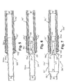
figure 3 est une vue en coupe longitudinale de la canalisation à embouts mâle et femelle de lafigure 2 mais avec en plus un dispositif réducteur de bruit inséré dans l'embout mâle conformément à l'enseignement du document précitéEP-A1-2 106 943 - la
figure 4 est une vue en coupe longitudinale d'une canalisation selon un premier mode de réalisation de l'invention qui se différencie uniquement de celle de lafigure 3 par l'embout femelle utilisé, le dispositif réducteur de bruit étant inchangé, - la
figure 5 est une vue en coupe longitudinale d'une autre canalisation à embouts mâle et femelle de l'art antérieur pour circuit de climatisation par exemple pour véhicule automobile, dépourvue de dispositif réducteur de bruit à l'instar de lafigure 2 , - la
figure 6 est une vue en coupe longitudinale de la canalisation de lafigure 5 mais avec en plus, à l'instar de lafigure 3 , le même dispositif réducteur de bruit inséré dans l'embout mâle, - la
figure 7 est une vue en coupe longitudinale d'une canalisation selon un second mode de réalisation de l'invention qui se différencie uniquement de celle de lafigure 6 par l'embout mâle utilisé, le dispositif réducteur de bruit étant inchangé, - la
figure 8 est un graphique illustrant pour cinq essais acoustiques réalisés respectivement avec les canalisations « témoin » desfigures 2, 3 et avec trois canalisations selon l'invention de lafigure 4 différant entre elles par ladite longueur L2, l'évolution de la fonction de transfert Ps/Pe (ratio entre pressions acoustiques de sortie et d'entrée) en fonction de la fréquence (Hz), et - la
figure 9 est un graphique correspondant à celui de lafigure 5 mais recadré à une plus grande échelle, montrant l'évolution de cette fonction de transfert pour la canalisation « témoin » de lafigure 3 et ces trois canalisations selon l'invention.
- the
figure 1 is a schematic view in perspective of an air conditioning circuit according to the invention for a motor vehicle, showing in particular two lines of low pressure and high pressure of gaseous or supercritical refrigerant with various examples of positioning of a pipe with a noise reducing device according to the invention, - the
figure 2 is a longitudinal sectional view of a piping with male and female nozzles of the prior art and devoid of noise reducing device, used in an air conditioning circuit for example for a motor vehicle, - the
figure 3 is a longitudinal sectional view of the male and female end pipe of thefigure 2 but in addition to a noise reducing device inserted into the male end according to the teaching of the aforementioned documentEP-A1-2 106 943 - the
figure 4 is a longitudinal sectional view of a pipe according to a first embodiment of the invention which differs only from that of thefigure 3 by the socket used, the noise reducing device being unchanged, - the
figure 5 is a longitudinal sectional view of another male and female pipe of the prior art for air conditioning circuit for example for a motor vehicle, without noise reducing device like thefigure 2 , - the
figure 6 is a longitudinal sectional view of the pipeline of thefigure 5 but with the added bonus offigure 3 , the same noise reducing device inserted in the male end, - the
figure 7 is a longitudinal sectional view of a pipe according to a second embodiment of the invention which differs only from that of thefigure 6 by the used male end, the noise reducing device being unchanged, - the
figure 8 is an illustrative graph for five acoustic tests carried out respectively with the "control"Figures 2, 3 and with three pipes according to the invention of thefigure 4 differing from each other by said length L2, the evolution of the transfer function Ps / Pe (ratio between output and input sound pressures) as a function of the frequency (Hz), and - the
figure 9 is a graph corresponding to that of thefigure 5 but reframed on a larger scale, showing the evolution of this transfer function for the "control" pipe of thefigure 3 and these three pipes according to the invention.
Le circuit de climatisation 1 illustré à la
Plus précisément, un circuit 1 selon l'invention comporte :
- une ligne basse pression 6, 6' destinée à véhiculer le fluide frigorigène gazeux entre le compresseur 2
et l'évaporateur 4, et un dispositif réducteur de bruit 300 ou 300' selon l'invention qui est différent des dispositifs connus de type capacités acoustiques et qui peut être monté en ligne dans une conduite 6 ou 6' (dans cette ligne 6, 6', les flèches A indiquent le sens de propagation du bruit généré par le compresseur 2 et les flèches B le sens de circulation du fluide qui est inverse du précédent) ; - une ligne haute
pression 8, 8' pour le fluide frigorigène gazeux ou supercritique qui est raccordée au compresseur 2 et au condenseur 3 et qui peut également incorporer en ligne un tel dispositif réducteur de bruit 300 ou 300' (dans cette ligne 8, 8', la flèche A' indique le sens de propagation du bruit généré par le compresseur 2 et la flèche B' le sens de circulation du fluide qui est le même que le précédent) ; et - une ligne haute pression liquide 9 qui est raccordée au condenseur 3 et à l'évaporateur 4 (dans cette ligne 9, la flèche B" indique le sens de circulation dudit fluide liquide).
- a low-
pressure line 6, 6 'intended to convey the gaseous refrigerant between the compressor 2 and theevaporator 4, and a noise-reducingdevice 300 or 300' according to the invention which is different from known devices of the acoustic capacity type and which can be mounted in line in aline 6 or 6 '(in thisline 6, 6', the arrows A indicate the direction of propagation of the noise generated by the compressor 2 and the arrows B the direction of circulation of the fluid which is opposite from the previous one); - a
high pressure line 8, 8 'for the gaseous or supercritical refrigerant which is connected to the compressor 2 and thecondenser 3 and which can also incorporate such anoise reducing device 300 or 300' in line (in thisline 8, 8 ' the arrow A 'indicates the propagation direction of the noise generated by the compressor 2 and the arrow B' the flow direction of the fluid which is the same as the previous one); and - a high-
pressure liquid line 9 which is connected to thecondenser 3 and the evaporator 4 (in thisline 9, the arrow B "indicates the flow direction of said liquid fluid).
On notera que les quatre emplacements illustrés à la
De manière connue, la capacité acoustique utilisée à ce jour dans la ligne basse pression 6, 6' comporte deux ouvertures respectivement d'entrée et de sortie pour le fluide frigorigène, et l'élargissement de la section de passage pour le fluide qui la caractérise permet d'atténuer les ondes sonores générées par le compresseur 2 et se propageant le long de cette ligne 6, 6'. En contrepartie, cette capacité présente l'inconvénient connu de générer des pertes de charge lors de sa traversée par le fluide.In known manner, the acoustic capacity used to date in the
La canalisation témoin 100 illustrée à la
Plus précisément, l'embout mâle 111 comporte un tronçon d'extrémité 111b formant un léger renflement radial qui se termine par un bord terminal 111a et qui est muni de joints d'étanchéité 111c (au nombre de deux dans cet exemple, étant précisé qu'un seul joint 111c serait utilisable en variante) pour recevoir en contact serré et étanche la face radialement interne de la portion élargie 112a de l'embout femelle 112.More specifically, the
Quant à cette portion élargie 112a de l'embout femelle 112, elle présente de manière connue une longueur totale réduite qui fait que sa longueur L2', mesurée axialement entre le bord terminal 111a et le début de cette portion 112a est quasiment nulle, étant par exemple au plus égale à 1 mm environ. Cette portion élargie 112a se termine classiquement par un court rebord 112b la prolongeant radialement vers l'extérieur, et elle naît d'un élargissement 112c sensiblement tronconique formé à partir d'une portion de base 112d cylindrique de diamètre interne nominal D0' (dans cet exemple identique à D0, ce qui donne pour l'ensemble de la canalisation 100 un diamètre interne nominal pour le fluide D = D0 = D0').As for this
Enfin, deux brides de fixation mâle 113 et femelle 114 pour le raccordement de la canalisation 100 à un organe du circuit de climatisation 1, tel que le compresseur 2, viennent enserrer de manière connue respectivement l'embout mâle 111 juste en retrait de son tronçon d'extrémité 111b, et l'embout femelle 112 en sa portion élargie 112a autour de son rebord 112b, de sorte que ces brides 113 et 114 juxtaposées axialement forment à elles deux un alésage traversant 115 recevant un organe de raccordement.Finally, two
La canalisation 200 de la
- un tronçon amont convergent 223 en forme d'hyperboloïde de révolution (i.e. avec une face radialement externe concave) dont l'extrémité interne (ou extrémité amont) 221 de forme circulaire forme avec la face interne de la paroi de l'embout mâle 111 un espace annulaire d'admission de fluide,
- un tronçon intermédiaire cylindrique 224 agencé de manière coaxiale à l'embout mâle 111, et
- un tronçon aval 225 tronconique qui diverge à partir du tronçon 224 et qui se termine par une collerette radiale constituant l'extrémité externe 222 qui est montée de manière étanche contre le bord terminal 111a de l'embout mâle 111 et qui forme l'extrémité extrémité aval du dispositif 220.
- a convergent
upstream portion 223 in the form of a hyperboloid of revolution (ie with a concave radial radially outer face) whose inner end (or upstream end) 221 of circular shape forms with the inner face of the wall of the male end piece 111 a annular fluid inlet space, - a cylindrical
intermediate section 224 arranged coaxially with themale end piece 111, and - a frustoconical
downstream section 225 which diverges from thesection 224 and which ends with a radial flange constituting theouter end 222 which is sealingly mounted against the terminal edge 111a of themale end piece 111 and which forms the end end downstream of thedevice 220.
On obtient ainsi un volume mort annulaire 240 radialement compris entre le dispositif 220 et la paroi cylindrique de l'embout mâle 111, avec l'espace interne à ce dernier situé en amont de l'extrémité 221 du dispositif 220 qui communique avec ce volume mort 240.An annular
On notera que la longueur L2" relative à la portion élargie 112a, mesurée à la
L'ensemble du dispositif 220 peut être entièrement réalisé en un matériau rigide tel que du métal ou en un matériau plastique rigide (e.g. un polyamide 6.6) ou, en variante, en un tel matériau rigide sauf pour le tronçon intermédiaire 224 qui peut être avantageusement réalisé en un caoutchouc de dureté Shore A voisine de 60, ou en un TPV.The
En référence à la description suivante de la
La canalisation 300 selon le premier mode de l'invention illustré à la
La canalisation 100' illustrée à la
La canalisation 200' illustrée à la
La canalisation 300' selon le second mode de l'invention qui est illustré à la
On a illustré à la
A l'instar du premier mode de l'invention illustré à la
Comme expliqué ci-dessus, on notera que le dispositif 220 est avantageusement monté, en référence à la
- à une extrémité de la conduite 6' de la ligne basse pression 6, 6' qui est raccordée au compresseur 2, de sorte que le dispositif 107 soit monté directement à l'aspiration de ce compresseur 2, ou bien
- à une extrémité de la conduite 8' de la ligne haute
pression 8, 8' qui est raccordée au compresseur 2, de sorte que le dispositif 107 soit monté directement sur le refoulement de ce compresseur 2.
- at one end of the pipe 6 'of the
low pressure line 6, 6' which is connected to the compressor 2, so that the device 107 is mounted directly to the suction of this compressor 2, or - at one end of the pipe 8 'of the
high pressure line 8, 8' which is connected to the compressor 2, so that the device 107 is mounted directly on the discharge of this compressor 2.
On notera toutefois que ces canalisations 300, 300' selon l'invention peuvent en variante être montées non seulement à une extrémité de conduite basse et/ou haute pression 6', 8', mais également ailleurs sur ces lignes 6, 6' et/ou 8, 8'.It should be noted, however, that these
La Demanderesse a réalisé cinq essais acoustiques T2, I1, I2, 13 respectivement avec les canalisations « témoin » 100 et 200 des
Ces essais acoustiques ont été réalisés avec de l'air à titre de fluide et en statique, dans des conditions normales de température (T ambiante) et de pression (P atmosphérique), étant précisé qu'un autre gaz produirait les mêmes courbes que celles des
Le graphique de la
Plus précisément et comme cela est encore plus clairement visible au graphique de la
Au vu de l'ensemble des essais réalisés, la Demanderesse a mis en évidence une plage optimale pour ladite longueur L2 qui est inclusivement comprise entre 1,5 . D et 2,4 . D environ, soit entre 25 mm et 40 mm environ.In view of all the tests carried out, the Applicant has demonstrated an optimum range for said length L2 which is included between 1.5. D and 2.4. Approximately, between 25 mm and 40 mm approximately.
Claims (15)
Priority Applications (1)
| Application Number | Priority Date | Filing Date | Title |
|---|---|---|---|
| PL13161856T PL2647513T3 (en) | 2012-04-03 | 2013-03-29 | Air conditioning circuit duct provided with a noise reducing device, and circuit including it |
Applications Claiming Priority (1)
| Application Number | Priority Date | Filing Date | Title |
|---|---|---|---|
| FR1253036A FR2988649B1 (en) | 2012-04-03 | 2012-04-03 | PIPE FOR AIR CONDITIONING CIRCUIT INCORPORATING A NOISE REDUCING DEVICE, AND SUCH A CIRCUIT INCORPORATING IT. |
Publications (2)
| Publication Number | Publication Date |
|---|---|
| EP2647513A1 true EP2647513A1 (en) | 2013-10-09 |
| EP2647513B1 EP2647513B1 (en) | 2014-09-10 |
Family
ID=47988868
Family Applications (1)
| Application Number | Title | Priority Date | Filing Date |
|---|---|---|---|
| EP20130161856 Active EP2647513B1 (en) | 2012-04-03 | 2013-03-29 | Air conditioning circuit duct provided with a noise reducing device, and circuit including it |
Country Status (9)
| Country | Link |
|---|---|
| US (1) | US9127800B2 (en) |
| EP (1) | EP2647513B1 (en) |
| KR (1) | KR102027006B1 (en) |
| CN (1) | CN103363650B (en) |
| AR (1) | AR090579A1 (en) |
| BR (1) | BR102013007909A2 (en) |
| ES (1) | ES2529656T3 (en) |
| FR (1) | FR2988649B1 (en) |
| PL (1) | PL2647513T3 (en) |
Cited By (1)
| Publication number | Priority date | Publication date | Assignee | Title |
|---|---|---|---|---|
| CZ308291B6 (en) * | 2014-04-10 | 2020-04-22 | Hanon Systems | Damping device and producing it |
Families Citing this family (6)
| Publication number | Priority date | Publication date | Assignee | Title |
|---|---|---|---|---|
| CN104913479B (en) * | 2015-06-09 | 2018-06-19 | 广东欧科空调制冷有限公司 | The pipe connecting structure, casing cooling device and air-conditioning equipment of noise can be reduced |
| KR101990401B1 (en) * | 2017-09-15 | 2019-06-18 | 엘지전자 주식회사 | Linear compressor |
| KR101990146B1 (en) * | 2018-01-12 | 2019-06-18 | 엘지전자 주식회사 | Linear compressor and refrigerator including the same |
| KR102575777B1 (en) * | 2018-08-13 | 2023-09-08 | 삼성전자주식회사 | Air conditioner |
| DE102021101639A1 (en) * | 2021-01-26 | 2022-07-28 | Röchling Automotive Se & Co.Kg | Distribution line component and thus modularly formed distributor assembly |
| CN113007483B (en) * | 2021-02-08 | 2021-11-26 | 哈尔滨工程大学 | Water source device of acoustic test water pipeline |
Citations (5)
| Publication number | Priority date | Publication date | Assignee | Title |
|---|---|---|---|---|
| EP1210694A2 (en) | 1999-08-25 | 2002-06-05 | General Instrument Corporation | A method and system for the provision of electronic commerce and shopping via cable television systems and associated entertainment terminals |
| EP1864838A1 (en) | 2006-06-06 | 2007-12-12 | Hutchinson | Noise-reduction device for automobile air-conditioning circuit, conduit and circuit comprising same |
| US7325570B1 (en) * | 2004-12-06 | 2008-02-05 | Coupled Products, Llc | Method and apparatus for noise suppression in a fluid line |
| EP2106943A1 (en) | 2008-03-31 | 2009-10-07 | Hutchinson | Fluid line with a noise reducing apparatus for a vehicle air conditioning circuit, and circuit incorporating such a fluid line |
| WO2012013874A1 (en) * | 2010-07-29 | 2012-02-02 | Maflow France Automotive | Device for attenuating the intensity of acoustical noise, and air-conditioning circuit including such a device |
Family Cites Families (9)
| Publication number | Priority date | Publication date | Assignee | Title |
|---|---|---|---|---|
| US5791141A (en) * | 1994-04-29 | 1998-08-11 | Techco Corp. | Method and apparatus for reduction of fluid borne noise in hydraulic systems |
| US7007718B2 (en) * | 1997-11-24 | 2006-03-07 | Dayco Products, Llc | Energy attenuation apparatus for a conduit conveying liquid under pressure, system incorporating same, and method of attenuating energy in a conduit |
| DE19848379A1 (en) * | 1998-10-21 | 2000-05-04 | Vickers Aeroquip Int Gmbh | Arrangement for damping a pulsation of a fluid conveyed by a conveying device |
| US7036530B2 (en) * | 1999-12-22 | 2006-05-02 | Dayco Products, Llc | Energy attenuation device for a fluid-conveying line and method of attenuating energy in such a line |
| US6848476B2 (en) * | 2003-06-13 | 2005-02-01 | Dana Corporation | Tuning cable |
| US20070281600A1 (en) * | 2006-05-31 | 2007-12-06 | Prakash Thawani | Air distribution system having a noise reduction feature for use with an automotive vehicle |
| JP2009202682A (en) * | 2008-02-27 | 2009-09-10 | Toyoda Gosei Co Ltd | Duct device for air conditioning |
| DE102009029875A1 (en) * | 2009-06-22 | 2010-12-30 | Airbus Operations Gmbh | Flow restrictor and use of a flow restrictor in an air distribution system of an air conditioning system of an aircraft |
| CN102759186B (en) * | 2012-07-16 | 2015-03-11 | 长城汽车股份有限公司 | Device for reducing noise of vehicle air conditioner air duct and vehicle air conditioner air duct using same |
-
2012
- 2012-04-03 FR FR1253036A patent/FR2988649B1/en not_active Expired - Fee Related
-
2013
- 2013-03-29 ES ES13161856.3T patent/ES2529656T3/en active Active
- 2013-03-29 PL PL13161856T patent/PL2647513T3/en unknown
- 2013-03-29 EP EP20130161856 patent/EP2647513B1/en active Active
- 2013-04-02 BR BRBR102013007909-0A patent/BR102013007909A2/en active Search and Examination
- 2013-04-03 US US13/855,887 patent/US9127800B2/en active Active
- 2013-04-03 KR KR1020130036428A patent/KR102027006B1/en active IP Right Grant
- 2013-04-03 CN CN201310115993.2A patent/CN103363650B/en active Active
- 2013-04-03 AR ARP130101074 patent/AR090579A1/en active IP Right Grant
Patent Citations (5)
| Publication number | Priority date | Publication date | Assignee | Title |
|---|---|---|---|---|
| EP1210694A2 (en) | 1999-08-25 | 2002-06-05 | General Instrument Corporation | A method and system for the provision of electronic commerce and shopping via cable television systems and associated entertainment terminals |
| US7325570B1 (en) * | 2004-12-06 | 2008-02-05 | Coupled Products, Llc | Method and apparatus for noise suppression in a fluid line |
| EP1864838A1 (en) | 2006-06-06 | 2007-12-12 | Hutchinson | Noise-reduction device for automobile air-conditioning circuit, conduit and circuit comprising same |
| EP2106943A1 (en) | 2008-03-31 | 2009-10-07 | Hutchinson | Fluid line with a noise reducing apparatus for a vehicle air conditioning circuit, and circuit incorporating such a fluid line |
| WO2012013874A1 (en) * | 2010-07-29 | 2012-02-02 | Maflow France Automotive | Device for attenuating the intensity of acoustical noise, and air-conditioning circuit including such a device |
Cited By (1)
| Publication number | Priority date | Publication date | Assignee | Title |
|---|---|---|---|---|
| CZ308291B6 (en) * | 2014-04-10 | 2020-04-22 | Hanon Systems | Damping device and producing it |
Also Published As
| Publication number | Publication date |
|---|---|
| KR20130112797A (en) | 2013-10-14 |
| BR102013007909A2 (en) | 2015-06-16 |
| CN103363650B (en) | 2017-12-22 |
| FR2988649A1 (en) | 2013-10-04 |
| ES2529656T3 (en) | 2015-02-24 |
| PL2647513T3 (en) | 2015-03-31 |
| EP2647513B1 (en) | 2014-09-10 |
| US20130255813A1 (en) | 2013-10-03 |
| KR102027006B1 (en) | 2019-09-30 |
| CN103363650A (en) | 2013-10-23 |
| FR2988649B1 (en) | 2014-04-25 |
| US9127800B2 (en) | 2015-09-08 |
| AR090579A1 (en) | 2014-11-19 |
Similar Documents
| Publication | Publication Date | Title |
|---|---|---|
| EP2647513B1 (en) | Air conditioning circuit duct provided with a noise reducing device, and circuit including it | |
| EP2295782B1 (en) | Silencing device for an intake line of a thermal engine and intake line incorporating a silencing device | |
| FR2924764A1 (en) | ACOUSTICAL ATTENUATION DEVICE FOR THE INTAKE LINE OF A THERMAL MOTOR, AND ADMISSION LINE INCORPORATING IT | |
| FR2781548A1 (en) | PIPE CONNECTION WITH ENLARGED METAL PIPE AND MANUFACTURING METHOD THEREOF | |
| EP2516270B1 (en) | Acoustic treatment panel having scalable thickness | |
| EP1780398B1 (en) | Intake silencer for a turbo compressed engine | |
| EP3601746B1 (en) | Central support for auxiliary tubes with elastic return | |
| EP1864838B1 (en) | Noise-reduction device for automobile air-conditioning circuit, conduit and circuit comprising same | |
| FR2912201A1 (en) | Noise attenuation device for internal combustion engine, has axial intake duct communicated with resonating chamber, where duct has two sections which are integrated to each other by its enlarged sections | |
| EP2106943B1 (en) | Fluid line with a noise reducing apparatus for a vehicle air conditioning circuit, and circuit incorporating such a fluid line | |
| WO2017207901A1 (en) | Housing of a gasket for a turbomachine injector | |
| FR2957396A1 (en) | AIR BLEED VALVE | |
| EP2072801B1 (en) | Vibration absorption sleeve for an injection pipe curvature | |
| EP2138750A1 (en) | Device for reducing acoustic interference with flexible implant and conditioning circuit including such a device | |
| EP1801486A1 (en) | Noise suppressor for hydraulic hose, hose with such a noise suppressor and power steering system comprising it | |
| EP3172516B1 (en) | Heat exchanger such as an internal exchanger for a motor vehicle air-conditioning system and system including same | |
| FR2991402A1 (en) | PROGRESSIVE CAVITY PUMP | |
| WO2012013874A1 (en) | Device for attenuating the intensity of acoustical noise, and air-conditioning circuit including such a device | |
| EP1821023B1 (en) | Noise reduction device for air-conditionning for vehicle | |
| EP2674606A2 (en) | Connection and sound attenuation system for intake line of a turbocharged engine, and said inlet line | |
| EP1498672A1 (en) | Tubular element for air conditioning circuit | |
| FR3097622A1 (en) | Noise reduction system | |
| FR3100847A1 (en) | Vacuum device and method for monitoring a deposit of reaction by-products | |
| FR3022006A1 (en) | MECHANICAL ASSEMBLY COMPRISING A SLEEVE, A DRIVE, A RECEIVER MEMBER, AND AT LEAST ONE FIXING DEVICE. | |
| FR3073596A1 (en) | IMPROVED TUBE / FLANGE ASSEMBLY FOR PRESSURIZING SYSTEM OF AERONAUTICAL EQUIPMENT |
Legal Events
| Date | Code | Title | Description |
|---|---|---|---|
| PUAI | Public reference made under article 153(3) epc to a published international application that has entered the european phase |
Free format text: ORIGINAL CODE: 0009012 |
|
| AK | Designated contracting states |
Kind code of ref document: A1 Designated state(s): AL AT BE BG CH CY CZ DE DK EE ES FI FR GB GR HR HU IE IS IT LI LT LU LV MC MK MT NL NO PL PT RO RS SE SI SK SM TR |
|
| AX | Request for extension of the european patent |
Extension state: BA ME |
|
| GRAP | Despatch of communication of intention to grant a patent |
Free format text: ORIGINAL CODE: EPIDOSNIGR1 |
|
| 17P | Request for examination filed |
Effective date: 20140306 |
|
| RBV | Designated contracting states (corrected) |
Designated state(s): AL AT BE BG CH CY CZ DE DK EE ES FI FR GB GR HR HU IE IS IT LI LT LU LV MC MK MT NL NO PL PT RO RS SE SI SK SM TR |
|
| RIC1 | Information provided on ipc code assigned before grant |
Ipc: F16L 55/033 20060101ALI20140327BHEP Ipc: B60H 1/00 20060101AFI20140327BHEP |
|
| INTG | Intention to grant announced |
Effective date: 20140414 |
|
| GRAS | Grant fee paid |
Free format text: ORIGINAL CODE: EPIDOSNIGR3 |
|
| GRAA | (expected) grant |
Free format text: ORIGINAL CODE: 0009210 |
|
| AK | Designated contracting states |
Kind code of ref document: B1 Designated state(s): AL AT BE BG CH CY CZ DE DK EE ES FI FR GB GR HR HU IE IS IT LI LT LU LV MC MK MT NL NO PL PT RO RS SE SI SK SM TR |
|
| REG | Reference to a national code |
Ref country code: GB Ref legal event code: FG4D Free format text: NOT ENGLISH |
|
| REG | Reference to a national code |
Ref country code: CH Ref legal event code: EP |
|
| REG | Reference to a national code |
Ref country code: IE Ref legal event code: FG4D Free format text: LANGUAGE OF EP DOCUMENT: FRENCH |
|
| REG | Reference to a national code |
Ref country code: AT Ref legal event code: REF Ref document number: 686482 Country of ref document: AT Kind code of ref document: T Effective date: 20141015 |
|
| REG | Reference to a national code |
Ref country code: DE Ref legal event code: R096 Ref document number: 602013000236 Country of ref document: DE Effective date: 20141023 |
|
| REG | Reference to a national code |
Ref country code: RO Ref legal event code: EPE |
|
| PG25 | Lapsed in a contracting state [announced via postgrant information from national office to epo] |
Ref country code: GR Free format text: LAPSE BECAUSE OF FAILURE TO SUBMIT A TRANSLATION OF THE DESCRIPTION OR TO PAY THE FEE WITHIN THE PRESCRIBED TIME-LIMIT Effective date: 20141211 Ref country code: LT Free format text: LAPSE BECAUSE OF FAILURE TO SUBMIT A TRANSLATION OF THE DESCRIPTION OR TO PAY THE FEE WITHIN THE PRESCRIBED TIME-LIMIT Effective date: 20140910 Ref country code: FI Free format text: LAPSE BECAUSE OF FAILURE TO SUBMIT A TRANSLATION OF THE DESCRIPTION OR TO PAY THE FEE WITHIN THE PRESCRIBED TIME-LIMIT Effective date: 20140910 Ref country code: NO Free format text: LAPSE BECAUSE OF FAILURE TO SUBMIT A TRANSLATION OF THE DESCRIPTION OR TO PAY THE FEE WITHIN THE PRESCRIBED TIME-LIMIT Effective date: 20141210 Ref country code: SE Free format text: LAPSE BECAUSE OF FAILURE TO SUBMIT A TRANSLATION OF THE DESCRIPTION OR TO PAY THE FEE WITHIN THE PRESCRIBED TIME-LIMIT Effective date: 20140910 |
|
| REG | Reference to a national code |
Ref country code: NL Ref legal event code: VDEP Effective date: 20140910 |
|
| REG | Reference to a national code |
Ref country code: ES Ref legal event code: FG2A Ref document number: 2529656 Country of ref document: ES Kind code of ref document: T3 Effective date: 20150224 |
|
| REG | Reference to a national code |
Ref country code: LT Ref legal event code: MG4D |
|
| REG | Reference to a national code |
Ref country code: FR Ref legal event code: PLFP Year of fee payment: 3 |
|
| PG25 | Lapsed in a contracting state [announced via postgrant information from national office to epo] |
Ref country code: HR Free format text: LAPSE BECAUSE OF FAILURE TO SUBMIT A TRANSLATION OF THE DESCRIPTION OR TO PAY THE FEE WITHIN THE PRESCRIBED TIME-LIMIT Effective date: 20140910 Ref country code: RS Free format text: LAPSE BECAUSE OF FAILURE TO SUBMIT A TRANSLATION OF THE DESCRIPTION OR TO PAY THE FEE WITHIN THE PRESCRIBED TIME-LIMIT Effective date: 20140910 Ref country code: LV Free format text: LAPSE BECAUSE OF FAILURE TO SUBMIT A TRANSLATION OF THE DESCRIPTION OR TO PAY THE FEE WITHIN THE PRESCRIBED TIME-LIMIT Effective date: 20140910 Ref country code: CY Free format text: LAPSE BECAUSE OF FAILURE TO SUBMIT A TRANSLATION OF THE DESCRIPTION OR TO PAY THE FEE WITHIN THE PRESCRIBED TIME-LIMIT Effective date: 20140910 |
|
| REG | Reference to a national code |
Ref country code: AT Ref legal event code: MK05 Ref document number: 686482 Country of ref document: AT Kind code of ref document: T Effective date: 20140910 |
|
| PG25 | Lapsed in a contracting state [announced via postgrant information from national office to epo] |
Ref country code: NL Free format text: LAPSE BECAUSE OF FAILURE TO SUBMIT A TRANSLATION OF THE DESCRIPTION OR TO PAY THE FEE WITHIN THE PRESCRIBED TIME-LIMIT Effective date: 20140910 |
|
| REG | Reference to a national code |
Ref country code: PL Ref legal event code: T3 |
|
| PG25 | Lapsed in a contracting state [announced via postgrant information from national office to epo] |
Ref country code: IS Free format text: LAPSE BECAUSE OF FAILURE TO SUBMIT A TRANSLATION OF THE DESCRIPTION OR TO PAY THE FEE WITHIN THE PRESCRIBED TIME-LIMIT Effective date: 20150110 Ref country code: PT Free format text: LAPSE BECAUSE OF FAILURE TO SUBMIT A TRANSLATION OF THE DESCRIPTION OR TO PAY THE FEE WITHIN THE PRESCRIBED TIME-LIMIT Effective date: 20150112 Ref country code: CZ Free format text: LAPSE BECAUSE OF FAILURE TO SUBMIT A TRANSLATION OF THE DESCRIPTION OR TO PAY THE FEE WITHIN THE PRESCRIBED TIME-LIMIT Effective date: 20140910 Ref country code: SK Free format text: LAPSE BECAUSE OF FAILURE TO SUBMIT A TRANSLATION OF THE DESCRIPTION OR TO PAY THE FEE WITHIN THE PRESCRIBED TIME-LIMIT Effective date: 20140910 Ref country code: EE Free format text: LAPSE BECAUSE OF FAILURE TO SUBMIT A TRANSLATION OF THE DESCRIPTION OR TO PAY THE FEE WITHIN THE PRESCRIBED TIME-LIMIT Effective date: 20140910 |
|
| PG25 | Lapsed in a contracting state [announced via postgrant information from national office to epo] |
Ref country code: AT Free format text: LAPSE BECAUSE OF FAILURE TO SUBMIT A TRANSLATION OF THE DESCRIPTION OR TO PAY THE FEE WITHIN THE PRESCRIBED TIME-LIMIT Effective date: 20140910 |
|
| REG | Reference to a national code |
Ref country code: DE Ref legal event code: R097 Ref document number: 602013000236 Country of ref document: DE |
|
| PLBE | No opposition filed within time limit |
Free format text: ORIGINAL CODE: 0009261 |
|
| STAA | Information on the status of an ep patent application or granted ep patent |
Free format text: STATUS: NO OPPOSITION FILED WITHIN TIME LIMIT |
|
| PG25 | Lapsed in a contracting state [announced via postgrant information from national office to epo] |
Ref country code: DK Free format text: LAPSE BECAUSE OF FAILURE TO SUBMIT A TRANSLATION OF THE DESCRIPTION OR TO PAY THE FEE WITHIN THE PRESCRIBED TIME-LIMIT Effective date: 20140910 |
|
| 26N | No opposition filed |
Effective date: 20150611 |
|
| PG25 | Lapsed in a contracting state [announced via postgrant information from national office to epo] |
Ref country code: MC Free format text: LAPSE BECAUSE OF FAILURE TO SUBMIT A TRANSLATION OF THE DESCRIPTION OR TO PAY THE FEE WITHIN THE PRESCRIBED TIME-LIMIT Effective date: 20140910 Ref country code: LU Free format text: LAPSE BECAUSE OF FAILURE TO SUBMIT A TRANSLATION OF THE DESCRIPTION OR TO PAY THE FEE WITHIN THE PRESCRIBED TIME-LIMIT Effective date: 20150329 |
|
| PG25 | Lapsed in a contracting state [announced via postgrant information from national office to epo] |
Ref country code: SI Free format text: LAPSE BECAUSE OF FAILURE TO SUBMIT A TRANSLATION OF THE DESCRIPTION OR TO PAY THE FEE WITHIN THE PRESCRIBED TIME-LIMIT Effective date: 20140910 |
|
| REG | Reference to a national code |
Ref country code: IE Ref legal event code: MM4A |
|
| PG25 | Lapsed in a contracting state [announced via postgrant information from national office to epo] |
Ref country code: IE Free format text: LAPSE BECAUSE OF NON-PAYMENT OF DUE FEES Effective date: 20150329 |
|
| REG | Reference to a national code |
Ref country code: FR Ref legal event code: PLFP Year of fee payment: 4 |
|
| REG | Reference to a national code |
Ref country code: CH Ref legal event code: PL |
|
| PG25 | Lapsed in a contracting state [announced via postgrant information from national office to epo] |
Ref country code: MT Free format text: LAPSE BECAUSE OF FAILURE TO SUBMIT A TRANSLATION OF THE DESCRIPTION OR TO PAY THE FEE WITHIN THE PRESCRIBED TIME-LIMIT Effective date: 20140910 |
|
| PG25 | Lapsed in a contracting state [announced via postgrant information from national office to epo] |
Ref country code: LI Free format text: LAPSE BECAUSE OF NON-PAYMENT OF DUE FEES Effective date: 20160331 Ref country code: CH Free format text: LAPSE BECAUSE OF NON-PAYMENT OF DUE FEES Effective date: 20160331 |
|
| REG | Reference to a national code |
Ref country code: FR Ref legal event code: PLFP Year of fee payment: 5 |
|
| PG25 | Lapsed in a contracting state [announced via postgrant information from national office to epo] |
Ref country code: BG Free format text: LAPSE BECAUSE OF FAILURE TO SUBMIT A TRANSLATION OF THE DESCRIPTION OR TO PAY THE FEE WITHIN THE PRESCRIBED TIME-LIMIT Effective date: 20140910 Ref country code: HU Free format text: LAPSE BECAUSE OF FAILURE TO SUBMIT A TRANSLATION OF THE DESCRIPTION OR TO PAY THE FEE WITHIN THE PRESCRIBED TIME-LIMIT; INVALID AB INITIO Effective date: 20130329 |
|
| PG25 | Lapsed in a contracting state [announced via postgrant information from national office to epo] |
Ref country code: BE Free format text: LAPSE BECAUSE OF NON-PAYMENT OF DUE FEES Effective date: 20150331 |
|
| PG25 | Lapsed in a contracting state [announced via postgrant information from national office to epo] |
Ref country code: TR Free format text: LAPSE BECAUSE OF FAILURE TO SUBMIT A TRANSLATION OF THE DESCRIPTION OR TO PAY THE FEE WITHIN THE PRESCRIBED TIME-LIMIT Effective date: 20140910 |
|
| GBPC | Gb: european patent ceased through non-payment of renewal fee |
Effective date: 20170329 |
|
| REG | Reference to a national code |
Ref country code: FR Ref legal event code: PLFP Year of fee payment: 6 |
|
| PG25 | Lapsed in a contracting state [announced via postgrant information from national office to epo] |
Ref country code: GB Free format text: LAPSE BECAUSE OF NON-PAYMENT OF DUE FEES Effective date: 20170329 |
|
| PG25 | Lapsed in a contracting state [announced via postgrant information from national office to epo] |
Ref country code: SM Free format text: LAPSE BECAUSE OF FAILURE TO SUBMIT A TRANSLATION OF THE DESCRIPTION OR TO PAY THE FEE WITHIN THE PRESCRIBED TIME-LIMIT Effective date: 20140910 |
|
| PG25 | Lapsed in a contracting state [announced via postgrant information from national office to epo] |
Ref country code: MK Free format text: LAPSE BECAUSE OF FAILURE TO SUBMIT A TRANSLATION OF THE DESCRIPTION OR TO PAY THE FEE WITHIN THE PRESCRIBED TIME-LIMIT Effective date: 20140910 |
|
| PG25 | Lapsed in a contracting state [announced via postgrant information from national office to epo] |
Ref country code: AL Free format text: LAPSE BECAUSE OF FAILURE TO SUBMIT A TRANSLATION OF THE DESCRIPTION OR TO PAY THE FEE WITHIN THE PRESCRIBED TIME-LIMIT Effective date: 20140910 |
|
| PGFP | Annual fee paid to national office [announced via postgrant information from national office to epo] |
Ref country code: RO Payment date: 20230316 Year of fee payment: 11 Ref country code: FR Payment date: 20230327 Year of fee payment: 11 |
|
| PGFP | Annual fee paid to national office [announced via postgrant information from national office to epo] |
Ref country code: PL Payment date: 20230217 Year of fee payment: 11 |
|
| P01 | Opt-out of the competence of the unified patent court (upc) registered |
Effective date: 20230526 |
|
| PGFP | Annual fee paid to national office [announced via postgrant information from national office to epo] |
Ref country code: IT Payment date: 20230328 Year of fee payment: 11 Ref country code: ES Payment date: 20230529 Year of fee payment: 11 |
|
| PGFP | Annual fee paid to national office [announced via postgrant information from national office to epo] |
Ref country code: DE Payment date: 20240320 Year of fee payment: 12 |