EP2647417A1 - Air dryer device - Google Patents
Air dryer device Download PDFInfo
- Publication number
- EP2647417A1 EP2647417A1 EP12163040.4A EP12163040A EP2647417A1 EP 2647417 A1 EP2647417 A1 EP 2647417A1 EP 12163040 A EP12163040 A EP 12163040A EP 2647417 A1 EP2647417 A1 EP 2647417A1
- Authority
- EP
- European Patent Office
- Prior art keywords
- air
- dryer
- air dryer
- temperature
- agent
- Prior art date
- Legal status (The legal status is an assumption and is not a legal conclusion. Google has not performed a legal analysis and makes no representation as to the accuracy of the status listed.)
- Granted
Links
- 239000012530 fluid Substances 0.000 claims abstract description 38
- 230000003993 interaction Effects 0.000 claims abstract description 23
- 238000000034 method Methods 0.000 claims abstract description 8
- 230000008929 regeneration Effects 0.000 claims description 32
- 238000011069 regeneration method Methods 0.000 claims description 32
- 238000012544 monitoring process Methods 0.000 claims description 20
- 238000011068 loading method Methods 0.000 claims description 11
- 230000002123 temporal effect Effects 0.000 claims description 11
- 239000003795 chemical substances by application Substances 0.000 description 79
- XLYOFNOQVPJJNP-UHFFFAOYSA-N water Substances O XLYOFNOQVPJJNP-UHFFFAOYSA-N 0.000 description 30
- 238000006243 chemical reaction Methods 0.000 description 14
- 239000002156 adsorbate Substances 0.000 description 9
- 238000003795 desorption Methods 0.000 description 9
- 238000000151 deposition Methods 0.000 description 6
- 238000001179 sorption measurement Methods 0.000 description 5
- 238000009833 condensation Methods 0.000 description 3
- 230000005494 condensation Effects 0.000 description 3
- 230000008021 deposition Effects 0.000 description 3
- 239000000463 material Substances 0.000 description 3
- 239000003463 adsorbent Substances 0.000 description 2
- 230000003247 decreasing effect Effects 0.000 description 2
- 238000010586 diagram Methods 0.000 description 2
- 230000000694 effects Effects 0.000 description 2
- 239000000284 extract Substances 0.000 description 2
- 238000007710 freezing Methods 0.000 description 2
- 230000008014 freezing Effects 0.000 description 2
- 230000006870 function Effects 0.000 description 2
- 239000008187 granular material Substances 0.000 description 2
- 230000000977 initiatory effect Effects 0.000 description 2
- 230000007257 malfunction Effects 0.000 description 2
- 239000002245 particle Substances 0.000 description 2
- 230000000717 retained effect Effects 0.000 description 2
- 230000002441 reversible effect Effects 0.000 description 2
- 239000007790 solid phase Substances 0.000 description 2
- XAGFODPZIPBFFR-UHFFFAOYSA-N aluminium Chemical compound [Al] XAGFODPZIPBFFR-UHFFFAOYSA-N 0.000 description 1
- 229910052782 aluminium Inorganic materials 0.000 description 1
- 238000013459 approach Methods 0.000 description 1
- 238000009529 body temperature measurement Methods 0.000 description 1
- 238000001816 cooling Methods 0.000 description 1
- 230000003111 delayed effect Effects 0.000 description 1
- 239000002274 desiccant Substances 0.000 description 1
- HNPSIPDUKPIQMN-UHFFFAOYSA-N dioxosilane;oxo(oxoalumanyloxy)alumane Chemical compound O=[Si]=O.O=[Al]O[Al]=O HNPSIPDUKPIQMN-UHFFFAOYSA-N 0.000 description 1
- 230000007613 environmental effect Effects 0.000 description 1
- 239000011796 hollow space material Substances 0.000 description 1
- 239000002808 molecular sieve Substances 0.000 description 1
- 230000003287 optical effect Effects 0.000 description 1
- 230000001151 other effect Effects 0.000 description 1
- 239000011236 particulate material Substances 0.000 description 1
- 239000012071 phase Substances 0.000 description 1
- 238000012545 processing Methods 0.000 description 1
- 229920006395 saturated elastomer Polymers 0.000 description 1
- URGAHOPLAPQHLN-UHFFFAOYSA-N sodium aluminosilicate Chemical compound [Na+].[Al+3].[O-][Si]([O-])=O.[O-][Si]([O-])=O URGAHOPLAPQHLN-UHFFFAOYSA-N 0.000 description 1
- 239000000725 suspension Substances 0.000 description 1
Images


Classifications
-
- B—PERFORMING OPERATIONS; TRANSPORTING
- B01—PHYSICAL OR CHEMICAL PROCESSES OR APPARATUS IN GENERAL
- B01D—SEPARATION
- B01D53/00—Separation of gases or vapours; Recovering vapours of volatile solvents from gases; Chemical or biological purification of waste gases, e.g. engine exhaust gases, smoke, fumes, flue gases, aerosols
- B01D53/26—Drying gases or vapours
- B01D53/261—Drying gases or vapours by adsorption
-
- B—PERFORMING OPERATIONS; TRANSPORTING
- B01—PHYSICAL OR CHEMICAL PROCESSES OR APPARATUS IN GENERAL
- B01D—SEPARATION
- B01D53/00—Separation of gases or vapours; Recovering vapours of volatile solvents from gases; Chemical or biological purification of waste gases, e.g. engine exhaust gases, smoke, fumes, flue gases, aerosols
- B01D53/02—Separation of gases or vapours; Recovering vapours of volatile solvents from gases; Chemical or biological purification of waste gases, e.g. engine exhaust gases, smoke, fumes, flue gases, aerosols by adsorption, e.g. preparative gas chromatography
- B01D53/04—Separation of gases or vapours; Recovering vapours of volatile solvents from gases; Chemical or biological purification of waste gases, e.g. engine exhaust gases, smoke, fumes, flue gases, aerosols by adsorption, e.g. preparative gas chromatography with stationary adsorbents
- B01D53/0407—Constructional details of adsorbing systems
- B01D53/0415—Beds in cartridges
-
- B—PERFORMING OPERATIONS; TRANSPORTING
- B60—VEHICLES IN GENERAL
- B60T—VEHICLE BRAKE CONTROL SYSTEMS OR PARTS THEREOF; BRAKE CONTROL SYSTEMS OR PARTS THEREOF, IN GENERAL; ARRANGEMENT OF BRAKING ELEMENTS ON VEHICLES IN GENERAL; PORTABLE DEVICES FOR PREVENTING UNWANTED MOVEMENT OF VEHICLES; VEHICLE MODIFICATIONS TO FACILITATE COOLING OF BRAKES
- B60T17/00—Component parts, details, or accessories of power brake systems not covered by groups B60T8/00, B60T13/00 or B60T15/00, or presenting other characteristic features
- B60T17/002—Air treatment devices
- B60T17/004—Draining and drying devices
-
- B—PERFORMING OPERATIONS; TRANSPORTING
- B01—PHYSICAL OR CHEMICAL PROCESSES OR APPARATUS IN GENERAL
- B01D—SEPARATION
- B01D2253/00—Adsorbents used in seperation treatment of gases and vapours
- B01D2253/10—Inorganic adsorbents
- B01D2253/104—Alumina
-
- B—PERFORMING OPERATIONS; TRANSPORTING
- B01—PHYSICAL OR CHEMICAL PROCESSES OR APPARATUS IN GENERAL
- B01D—SEPARATION
- B01D2253/00—Adsorbents used in seperation treatment of gases and vapours
- B01D2253/10—Inorganic adsorbents
- B01D2253/106—Silica or silicates
- B01D2253/108—Zeolites
-
- B—PERFORMING OPERATIONS; TRANSPORTING
- B01—PHYSICAL OR CHEMICAL PROCESSES OR APPARATUS IN GENERAL
- B01D—SEPARATION
- B01D2257/00—Components to be removed
- B01D2257/80—Water
-
- B—PERFORMING OPERATIONS; TRANSPORTING
- B01—PHYSICAL OR CHEMICAL PROCESSES OR APPARATUS IN GENERAL
- B01D—SEPARATION
- B01D2259/00—Type of treatment
- B01D2259/40—Further details for adsorption processes and devices
- B01D2259/40007—Controlling pressure or temperature swing adsorption
- B01D2259/40009—Controlling pressure or temperature swing adsorption using sensors or gas analysers
-
- B—PERFORMING OPERATIONS; TRANSPORTING
- B01—PHYSICAL OR CHEMICAL PROCESSES OR APPARATUS IN GENERAL
- B01D—SEPARATION
- B01D2259/00—Type of treatment
- B01D2259/45—Gas separation or purification devices adapted for specific applications
- B01D2259/4566—Gas separation or purification devices adapted for specific applications for use in transportation means
Definitions
- the present invention pertains to an air dryer device, an air dryer cartridge, as well as a method of controlling an air dryer device.
- an air dryer device is usually provided to extract moisture and possibly other undesired elements, i.e., particulate elements, from an air stream.
- An air dryer usually comprises an air dryer cartridge in which a dryer agent is arranged, and may also include a valve housing comprising valves and connection ports as well as an electronic control unit. The dryer agent extracts water from an air flow.
- air dryer devices usually comprise a so-called regeneration mode or regeneration function in which an air flow direction is reversed, and dry air is streamed through the moist dryer agent. The dry air removes water from the dryer agent, so that the air dryer device functions with increased efficiency after regeneration.
- An object of the present invention is to provide an air dryer device in which the efficiency of an air dryer device, in particular the dryer agent, and/or the efficiency of a regeneration mode may be increased.
- the present invention pertains to an air dryer device, in particular for a vehicle, comprising an air dryer cartridge with a housing, the housing containing a dryer agent, as well as first air port providing fluid connection to the housing and a second air port providing fluid connection to the housing.
- the air dryer cartridge comprises a fluid guide providing a fluid connection between the first air port and the second air port, the fluid guide being arranged to allow interaction between an air stream flowing through the fluid guide and the dryer agent.
- the air dryer device further comprises a temperature sensor device adapted to monitor a temperature change due to an interaction between the air stream and the dryer agent. It has been recognized that the interaction of an air stream with the dryer agent, in particular depositing water to the dryer agent or removing water from the dryer agent, is an enthalpic reaction.
- depositing water onto a dryer agent may be an exothermal reaction, raising the temperature of the air stream, the dryer agent, and possibly components in close physical contact thereof.
- the adsorption of water by a dryer agent and condensation of water onto a dryer agent are exothermal reactions.
- removing water from a dryer agent may require heat, and thus may be an endothermal reaction.
- Desorption of water from a dryer agent may be seen as an example of such an endothermal reaction.
- an air dryer device may be connected or connectable to a compressor providing air, in particular pressurized air.
- an air dryer device comprises one or more valves and or ports. It may also comprise one or more sensors, e.g., pressure sensors, and may comprise or be connected or connectable to an electronic control unit.
- An air dryer device may be connected to an air storage device and/or a consumer system to be provided with dried air.
- the first air port may be directly or indirectly connected or connectable to a compressor, and/or the second air port may be directly or indirectly connected or connectable to an air storage or a consumer system.
- a fluid connection may be seen as a connection enabling a fluid, in particular air, to flow between connected elements or components.
- a fluid guide may generally provide a channel or hollow space through which a fluid may flow.
- a fluid guide is arranged inside a housing of an air dryer cartridge.
- the fluid guide may comprise a space in which dryer agent is arranged. It may be adapted to guide an air stream to contact particles or elements of the dryer agent when flowing through the fluid guide.
- An air dryer cartridge may generally be detachably or non-detachably connected to the air dryer device. As such, it may be a separate part or an integral part of the air dryer device.
- the air dryer cartridge may comprise the first air port, which may be in fluid connection with a corresponding port of the air dryer device, and the second air port, which also may be in fluid connection with a corresponding connection port.
- Interaction of an air stream with the dryer agent may refer to the air stream flowing in contact with elements of the dryer agent such that water and/or moisture may be deposited onto the dryer agent or that the air stream may remove water and/or moisture from the dryer agent.
- a dryer agent may generally be a material adapted to extract water out of an air stream, e.g., via adsorption and/or condensation.
- the dryer agent may comprise particulate and/or granulate material.
- a dryer agent may comprise an adsorbent.
- a dryer agent may comprise a molecular sieve, e.g., a zeolith material, or an aluminum-based material.
- Monitoring a temperature change may comprise measuring and/or comparing several measured temperature values.
- a sensor device adapted to measure a temperature and provide signals based on which a temperature change may be determined may be considered to be adapted to monitor a temperature change.
- a temperature sensor device may comprise one or more temperature sensors. It may be considered that the temperature sensor device and/or sensors of the temperature sensor device are adapted to provide signals indicative of a temperature sensed and/or a temperature change. Generally, a temperature change may be determined based on temperature measurements.
- a temperature change may be a spatial change in temperature, e.g., between different locations or different parts of an air stream, and/or a temporal change representing a change in temperature over time at one or more given locations.
- a temperature sensor device adapted to monitor a temperature change due to interaction between the air stream and the dryer agent may be considered to comprise at least one temperature sensor arranged at the location in which it is able to detect a corresponding temperature change.
- One or more temperature sensors of the temperature sensor device may be arranged inside the housing, in particular in contact with the air stream and/or the dryer agent.
- a sensor outside of the housing and/or the air dryer cartridge and/or in close proximity to the first air port or the second air port in the path of an air stream to be flowed through the air dryer cartridge.
- one or more temperature sensors may be provided in a channel of a valve housing providing a fluid connection to the first air port and/or one or more temperature sensors may be provided in a channel of a valve housing providing a fluid connection to the second air port.
- a temperature sensor may be a contact sensor or a non-contact sensor, e.g. an infrared sensor.
- An infrared sensor may, e.g., be arranged outside of the housing to detect changes in temperature of the housing indicative of a temperature change due to interaction between an air stream and the dryer agent.
- a temperature sensor device may be adapted to monitor a spatial and/or temporal temperature change due to an interaction between the air stream and the dryer agent.
- the air dryer device is arranged such that it comprises a first operational mode, in which air may flow from the first air port to the second air port via the fluid guide, and that it comprises a second operational mode, in which air may flow from the second air port to the first air port via the fluid guide.
- a first operational mode in which air may flow from the first air port to the second air port via the fluid guide
- a second operational mode in which air may flow from the second air port to the first air port via the fluid guide.
- an air stream flowing via the fluid guide may interact with the dryer agent.
- the first operational mode may be a loading mode in which air to be dried is provided to the first air port, flows via the fluid guide through the dryer agent, interacts with the dryer agent, and then leaves the air dryer cartridge via the second air port. In this mode, air may be dried when it interacts with the air dryer cartridge.
- the second operational mode may represent a reverse flow of air.
- the second operational mode may be a regeneration mode, in which dry air, e.g., from an air storage
- the temperature sensor device may be connected or connectable to an electronic control unit.
- a connection may refer to a connection via which the temperature sensor device may transmit and/or receive signals from the electronic control unit.
- the temperature sensor device may be adapted to transmit signals representing a measured temperature and/or a temperature change to the electronic control unit.
- the electronic control unit may be adapted to receive and/or process signals from the temperature sensor device.
- the air dryer device may be adapted to be controlled by an electronic control unit. This may improve the level of control and the efficiency of regeneration.
- the electronic control unit may be adapted to control the first and/or second operational mode based on signals from the temperature sensor device. It may generally be considered that the electronic control unit is adapted to monitor whether the direction or sign of a temperature change stalls or changes, in particular during one of the operational modes. A stall or change in sign of a temperature change may be considered to be indicative for the dryer agent having reached an equilibrium or saturation regarding deposition or removal of water in the current operational mode. Stalling may refer to no essential change of temperature occurring over a predetermined time. A change in temperature change may be represented by a temperature beginning to increase after decreasing or to decrease after increasing.
- the electronic control unit may be adapted to monitor whether in a first operational mode a temperature change changes from an increase in temperature to a decrease in temperature.
- the electronic control unit may be adapted to monitor whether in a second operational mode a temperature change changes from a decrease in temperature to an increase in temperature.
- the electronic control unit may generally be adapted to switch the air dryer device between operational modes when it detects a stall or change in the sign of the temperature change.
- An electronic control unit may be adapted to monitor and/or determine the temporal and/or spatial change of temperature based on signals from the temperature sensor device. It may be considered that the electronic control unit is adapted to control the air dryer device based on the monitored change. In particular, it may be considered that an electronic control unit is adapted to end a first operational mode when an increase in measured temperature stalls for a predetermined time or changes to a decrease. It may be considered that the electronic control unit is adapted to end a second operational mode, in particular a regeneration mode, when a decrease in temperature stalls for a predetermined time or changes to an increase. Generally, the electronic control unit may be adapted to determine a local minimum or local maximum of the temperature. A local minimum may be indicative of a regeneration mode reaching equilibrium or saturation.
- a local maximum may be indicative of a loading mode reaching equilibrium or saturation.
- the electronic control unit may be adapted to end an operational mode when it determines that equilibrium or saturation is reached and to switch to the other operational mode. It may be considered that the electronic control unit is adapted to determine a temperature difference between different locations and/or sensors, which may be representative of a spatial temperature change. The electronic control unit may be adapted to control the air dryer device based on this temperature difference. For example, it may be adapted to determine whether a given temperature difference has been reached or check the temporal behavior of the temperature difference.
- the electronic control unit is adapted to switch the air dryer device between the first operational mode and the second operational mode based on signals from the temperature sensor device. Switching between the first operational mode and the second operational mode may be performed when the respective other mode is controlled to be ended.
- the first operational mode may be a loading mode in which the air dryer device is controlled to flow air to be dried through the air dryer cartridge
- the second operational mode may be a regeneration mode.
- the dry air may be controlled to flow through the air dryer cartridge to remove water and/or moisture from the dryer agent.
- the temperature sensor device may comprise at least one temperature sensor arranged in the housing and/or in contact with the dryer agent and/or in the path of an air stream entering or leaving the first air port and/or the second air port and/or in contact with the housing. It may be considered to arrange at least one temperature sensor in the path of an air stream flowing through the first air port and/or a further temperature sensor in the path of an air stream flowing through the second air port. Such sensors may be arranged in close proximity to the respective air port. It may be considered to provide one or more than one temperature sensors inside the housing of the air dryer cartridge.
- one or more temperature sensors may be arranged outside of the cartridge and/or the housing of the cartridge, in particular in the flow path of an air stream close to at least one of the first air port and the second air port.
- Such an arrangement allows spatial monitoring of a temperature change such that, for example, it may be determined whether the air flowing through the first air port is warmer or colder than the air flowing through the second air port due to an interaction of the air stream with the dryer agent.
- it may be considered to provide two or more temperature sensors at different locations inside the housing, for example, in contact with the dryer agent. Accordingly, it is possible to determine locally at several positions whether saturation or equilibrium occurs.
- the present invention also pertains to an air dryer cartridge comprising a housing containing a drying agent, the air dryer cartridge being adapted to be detachably attached to an air dryer device, in particular an air dryer device being described herein.
- the air dryer cartridge further comprises a temperature sensor device adapted to monitor a temperature change due an interaction between the air stream and the dryer agent.
- the cartridge may be a cartridge as described above and in particular may comprise a first air port, a second air port and a fluid guide.
- Such an air dryer cartridge may be used for monitoring a temperature change, based on which the air dryer device may be controlled without necessitating changes to an air dryer device. It may be considered that the temperature sensor device may be connected or connectable to an electronic control unit.
- the temperature sensor device may comprise one or more sensors, which may be arranged inside the housing, in particular in physical contact with the dryer agent and/or an air stream interacting with the dryer agent.
- the invention also pertains to a method of controlling an air dryer device, in particular, an air dryer device as described herein and/or comprising an air dryer cartridge as described herein.
- the method may comprise the steps of monitoring a spatial and/or temporal temperature change due to interaction between an air stream and a dryer agent and controlling the air dryer device based on the monitoring.
- the monitoring and controlling may be performed by an electronic control unit and/or a temperature sensor device.
- a vehicle may be a utility vehicle or a railway vehicle.
- a vehicle may comprise a pneumatic brake as a consumer of dry and/or pressurized air.
- An electronic control unit may be integrated into an air dryer device or may be arranged separately.
- a connection to transmit data or signals and/or receive data or signals, in particular to and/or from an electronic control unit, e.g. via a connection to the temperature sensor device, may be provided via an electrical and/or optical cable and/or via radio and/or via a wireless connection.
- An electronic control unit may generally be provided with signals from sensors, in particular from the temperature sensor device.
- controlling may refer to initiating and/or ending a first operational mode and/or a second operational mode and/or switching between the first operational mode and the second operational mode. It may be considered that controlling by an electronic control unit in particular refers to initiating a regeneration mode and/or a loading mode and/or ending a regeneration mode and/or loading mode.
- an electronic control unit may be part of an air dryer device and/or a temperature sensor device or it may be implemented separately.
- a sensor or sensor device may be considered to be adapted to monitor a temperature change due to an interaction between the air stream and the dryer agent if it is arranged such that it may monitor a location in heat conductive contact with the dryer agent or the air stream in which the temperature change due to the interaction is not overshadowed by other effects, e.g., heat produced by a compressor, cooling effects due to headwind, etc.
- the electronic control unit is adapted to receive a signal indicating an outside temperature and/or to control the air dryer device based on an outside temperature.
- the outside temperature may represent an environmental temperature and/or a temperature outside of the housing of the air dryer cartridge.
- the electronic control unit may be connected or connectable to a corresponding temperature sensor arranged to measure the outside temperature.
- monitoring the temperature change emphasizes relative temperature values but not absolute temperature values.
- the outside temperature may generally have an influence on the exact behavior of a temperature change, but is not expected to change the general shape of a curve describing the behavior of a temperature and/or the temperature change.
- monitoring a temperature change as described herein can be useful for a plurality of purposes. It may be performed to monitor and control an air dryer device during operation. Further, an air dryer device may be calibrated based on such monitoring. Generally, it may be considered that the electronic control unit is adapted to receive calibration data from a connected storage.
- the calibration data may pertain to the behavior of the temperature change to be expected under different conditions, e.g., depending on outside temperatures, pressure conditions, duration periods of operation in a given operational mode, etc. It may be considered to determine the amount of air necessary for a regeneration mode to reach equilibrium and/or the amount of air to be dried until a loading mode reaches equilibrium. Based on these amounts, suitable amounts of air and/or operation durations may be defined for a regeneration mode and/or a loading mode. In this context it may be considered that the efficiency of a dryer agent is reduced even before reaching equilibrium, such that a maximum load of air to be dried may be lower than the amount of air necessary to be dried to reach equilibrium.
- the electronic control unit is adapted to determine whether a regeneration started or ended based on monitoring the temperature change. This provides an easy approach to independently check for errors during the regeneration mode.
- the electronic control unit may be adapted to determine a current state of regeneration based on monitoring the temperature change. It may be considered that the electronic control unit is adapted to determine the current state based on an outside temperature and/or calibration data indicating the expected behavior of the temperature change under given conditions, which may be stored in a memory.
- the electronic control unit may be adapted to determine the efficiency of depositing water to the dryer agent, in particular the efficiency of adsorption, and/or removal of water from the dryer agent, in particular the desorption of water, based on monitoring the temperature change.
- the electronic control unit may be adapted to determine the residual wetness in the dryer agent, in particular an adsorbent, and/or estimate the lifetime of the dryer agent and/or detect damage of the dryer agent and/or detect a malfunction of the air dryer device, in particular regarding the control of the air dryer device, based on monitoring the temperature change.
- the electronic control unit may be adapted to determine the condensation of water downstream of the dryer agent and/or detect freezing based on monitoring the temperature change. It may be considered that the electronic control unit is adapted to provide a warning signal and/or status information regarding the dryer agent and/or the operational modes, e.g. to a vehicle computer, for example via a commonly used bus, which may be a CAN-Bus.
- the electronic control unit may be adapted to control the inlet flow temperature based on monitoring the temperature change.
- monitoring the temperature change as described above provides a plurality of options to monitor and/or control the air dryer device.
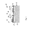
- FIG 1 schematically shows the interaction of an air stream 20 containing an adsorbate 18 in the form of water with a dryer agent 10.
- the dryer agent 10 comprises a solid phase 12 and a boundary surface 14 comprising active sites 16.
- the active sites 16 may be distributed homogenously (left side of Figure 1 ) or heterogeneously (right side of Figure 1 ).
- the adsorbate 18 may react with one of the active sites 16.
- the adsorbate 18 may be provided in a gas phase of the air stream 20. In the boundary area, reactions between the active sides and the adsorbate 18 may occur.
- adsorbate 18 may be adsorbed at an active site 16, representing an exothermal reaction which produces heat. Such a reaction is indicated by arrow 22.
- adsorbate 18 may be removed from an active site 16 and enter the air stream 20, undergoing a desorption reaction, which is indicated by arrow 24.
- This reaction requires energy and is endothermal. Exothermal reactions lead to an increase in temperature of the environment, in particular the dryer agent 10, the adsorbate 18 and the air stream 20. In contrast, endothermal reactions decrease the temperature of the environment. In a situation in which adsorption dominates desorption, e.g., when moist air flows through a dryer agent having adsorbate 10 with relatively high amount of active sides 16 not yet retaining water, an overall increase in temperature occurs. On the other hand, if regeneration is performed on the dryer agent 10 retaining a significant amount of water, desorption is dominant, decreasing the temperature of the environment.
- FIG 2 schematically shows an example for an air dryer cartridge 100 arranged on an air dryer device 102, which is not shown in detail.
- the air dryer device 102 comprises the usual components such as a valve housing, a compressor inlet port, which may be connected to a compressor, and an outlet port which may be connected to a consumer system and/or an air storage.
- the air dryer cartridge 100 comprises a housing 104 containing a dryer agent 106, which in this example is provided in granulate form and may extract moisture from an air stream.
- a first air port 108 and a second air port 110 are provided in the housing 104.
- the housing 104 generally may be enclosed by an outer housing 105 of the air dryer device 102 or the air dryer cartridge 100.
- Air may enter or leave the housing 104 through one of the ports 108, 110.
- the air dryer device 102 may be operated in the first operational mode such that an air stream to be dried flows through first air port 108, through the dryer agent 106, and then leaves the housing 104 through the second air port 110 to be guided to an air storage or a consumer system.
- the first operational mode may be seen as a loading mode.
- the air flow is reversed such that dry air from a consumer system or the air storage may flow through the second air port 110, interacts with the dryer agent 106 to remove moisture and/or water and subsequently leave the housing 104 through the first air port 108.
- the housing 104 may be considered to form a fluid guide connecting the first air port 108 and the second air port 110 and allowing interaction between an air stream and the dryer agent 106.
- a first temperature sensor 112 may be arranged inside the housing in contact with the dryer agent 106. It may be considered that the first temperature sensor 112 is arranged closed to the first air port 108. In particular, it may be arranged in the extension of the general flow direction of an air stream flowing through the first air port 108.
- a second temperature sensor 114 may be arranged inside the housing 104 in contact with the dryer agent 106. The second temperature sensor 114 may be arranged close to the second air port 110, preferably in an extension of a flow direction of an air stream going through the second air port 110.
- the temperature sensors 112, 114 may be considered to be parts of a temperature sensor device. With this arrangement, it is possible to monitor the temporal behavior of a temperature change at the location of each temperature sensor 112, 114. it is also possible to determine a spatial temperature change showing the change in temperature between the locations of the temperature sensors 112, 114. It should be understood that alternatively or additionally one or more temperature sensors may be arranged in a channel connected to the first air port 108 and/or in a channel connected to the second air port 110. The sensors may be arranged outside of the housing 104 in which the dryer agent 106 is contained. In particular, temperature sensors may be arranged in corresponding channels outside of the air cartridge, but preferably inside the air dryer device 102, such that they may be exchanged separately from the air dryer cartridge.
- a temperature sensor may be arranged at or close to a connection port 116 and/or 118, which provide fluid connections between the air dryer cartridge 100 and the valve housing of air dryer device 102.
- the temperature sensors 112, 114 may be connected to an electronic control unit via a wireless connection, e.g. a radio connection.
- Figure 3 shows an example of the temporal behavior of the temperature in different operational modes in an air dryer cartridge as shown in Figure 2 .
- the x-axis corresponds to time, whereas the vertical y-axis corresponds to the measured temperature.
- the steps on the x-axis correspond to 2 seconds, whereas the steps on the y-axis correspond to 0.5 degrees Celsius.
- Graph I represents the state of the air dryer device. At second 2, a regeneration mode is started which roughly lasts until second 39. After this regeneration mode, the air dryer device is put into the loading mode in which air to be dried is provided by a compressor.
- the different operational modes are indicated by the step-like structure of graph I.
- Graph II represents the temperature measured at temperature sensor 114 of Figure 2 in the lower region of housing 100, close to the second air port 110.
- Graph III represents the temperature as measured by temperature sensor 112 arranged close to first port 108 in Figure 2 in the upper region of port 114.
- the regeneration mode is started, the temperature measured at temperature sensors 112, 114 drops due to desorption, which requires heat. The drop in temperature continues until equilibrium is reached.
- the regeneration mode is still performed after equilibrium is reached, the temperature starts to rise again. This is due to the effect that the impact of the air stream leads to friction and heats the dryer agent. It can be seen from Figure 3 that there is a significant delay between the behavior close to the second air port 110 and that close to the first air port 108.
- the temperature increase around the first temperature sensor 110 is more pronounced. It can be easily seen that a good criterion for stopping regeneration is when the direction of a temperature change during a regeneration mode stalls or changes from a decrease to an increase, indicating that no further significant desorption or removal of moisture from a dryer agent may be expected. Analogously, when deciding whether regeneration has to be performed, a change in the direction of the temperature change may indicate that the dryer agent is saturated or has reached equilibrium and cannot efficiently dry an air stream without regeneration.
- an electronic control unit is adapted to end a regeneration mode if the last of the temperature sensors indicates that saturation or equilibrium has been (locally) reached, in particular if no interrupting event like an inadmissible drop of pressure occurs. Also, it may be generally considered that an electronic control unit is adapted to end a loading mode if the first or several, but not all, sensors indicate that saturation or equilibrium has been (locally) reached.
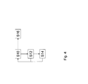
- FIG. 4 shows a flow diagram of a method of controlling an air dryer device.
- a spatial and/or temporal temperature change due to an interaction between an air stream and a dryer agent is monitored, e.g., by a temperature sensor device providing corresponding signals to an electronic control unit.
- an electronic control unit may determine if a saturation or equilibrium is reached at least locally, e.g., by determining whether a local minimum or maximum of the temperature is reached, as shown, for example, in Fig. 3 . If saturation or maximum is reached, in a step S14 the electronic control unit controls the air dryer unit to switch its operational mode. From there, it may be returned to step S10. Otherwise, it is directly returned to step S10.
- step S16 the operational status of the air dryer device is monitored based on the signals of the temperature sensor device. In particular, it may be monitored whether the air dryer device or one of its valve components malfunction or freezing occurs by monitoring the behavior of the temperature change and, if suitable, to compare it with calibration data indicating an expected behavior under given conditions. It should be understood that step S16 does not have to be performed in parallel, but could be included into the steps S10 to S14.
Landscapes
- Chemical & Material Sciences (AREA)
- Engineering & Computer Science (AREA)
- Analytical Chemistry (AREA)
- General Chemical & Material Sciences (AREA)
- Oil, Petroleum & Natural Gas (AREA)
- Chemical Kinetics & Catalysis (AREA)
- Transportation (AREA)
- Mechanical Engineering (AREA)
- Drying Of Gases (AREA)
Abstract
Description
- The present invention pertains to an air dryer device, an air dryer cartridge, as well as a method of controlling an air dryer device.
- For many modern systems, it is necessary to provide dried air, which may be pressurized air. For example, dried air is used in food processing. Dried air is also of particular relevance for modern vehicles such as utility vehicles or trains, in which pressurized air is used to power important systems like brakes or suspensions. To avoid moisture damaging the pneumatic systems using the air, an air dryer device is usually provided to extract moisture and possibly other undesired elements, i.e., particulate elements, from an air stream. An air dryer usually comprises an air dryer cartridge in which a dryer agent is arranged, and may also include a valve housing comprising valves and connection ports as well as an electronic control unit. The dryer agent extracts water from an air flow. Extracted water is usually retained in the dryer agent, and it is required to rid the dryer agent of retained water now and again. For this purpose, air dryer devices usually comprise a so-called regeneration mode or regeneration function in which an air flow direction is reversed, and dry air is streamed through the moist dryer agent. The dry air removes water from the dryer agent, so that the air dryer device functions with increased efficiency after regeneration.
- An object of the present invention is to provide an air dryer device in which the efficiency of an air dryer device, in particular the dryer agent, and/or the efficiency of a regeneration mode may be increased.
- The present invention pertains to an air dryer device, in particular for a vehicle, comprising an air dryer cartridge with a housing, the housing containing a dryer agent, as well as first air port providing fluid connection to the housing and a second air port providing fluid connection to the housing. The air dryer cartridge comprises a fluid guide providing a fluid connection between the first air port and the second air port, the fluid guide being arranged to allow interaction between an air stream flowing through the fluid guide and the dryer agent. The air dryer device further comprises a temperature sensor device adapted to monitor a temperature change due to an interaction between the air stream and the dryer agent. It has been recognized that the interaction of an air stream with the dryer agent, in particular depositing water to the dryer agent or removing water from the dryer agent, is an enthalpic reaction. For example, depositing water onto a dryer agent may be an exothermal reaction, raising the temperature of the air stream, the dryer agent, and possibly components in close physical contact thereof. In particular, the adsorption of water by a dryer agent and condensation of water onto a dryer agent are exothermal reactions. On the other hand, removing water from a dryer agent may require heat, and thus may be an endothermal reaction. Desorption of water from a dryer agent may be seen as an example of such an endothermal reaction. Generally, the interaction of an air stream with a dryer agent requires or produces heat until an equilibrium or saturation is reached, in which essentially no further net deposition or removal of water occurs. In the context of this description, an air dryer device may be connected or connectable to a compressor providing air, in particular pressurized air. It may be considered that an air dryer device comprises one or more valves and or ports. It may also comprise one or more sensors, e.g., pressure sensors, and may comprise or be connected or connectable to an electronic control unit. An air dryer device may be connected to an air storage device and/or a consumer system to be provided with dried air. In particular, the first air port may be directly or indirectly connected or connectable to a compressor, and/or the second air port may be directly or indirectly connected or connectable to an air storage or a consumer system. A fluid connection may be seen as a connection enabling a fluid, in particular air, to flow between connected elements or components. A fluid guide may generally provide a channel or hollow space through which a fluid may flow. It may be considered that a fluid guide is arranged inside a housing of an air dryer cartridge. The fluid guide may comprise a space in which dryer agent is arranged. It may be adapted to guide an air stream to contact particles or elements of the dryer agent when flowing through the fluid guide. An air dryer cartridge may generally be detachably or non-detachably connected to the air dryer device. As such, it may be a separate part or an integral part of the air dryer device. In particular, the air dryer cartridge may comprise the first air port, which may be in fluid connection with a corresponding port of the air dryer device, and the second air port, which also may be in fluid connection with a corresponding connection port. Interaction of an air stream with the dryer agent may refer to the air stream flowing in contact with elements of the dryer agent such that water and/or moisture may be deposited onto the dryer agent or that the air stream may remove water and/or moisture from the dryer agent. A dryer agent may generally be a material adapted to extract water out of an air stream, e.g., via adsorption and/or condensation. The dryer agent may comprise particulate and/or granulate material. A dryer agent may comprise an adsorbent. For example, a dryer agent may comprise a molecular sieve, e.g., a zeolith material, or an aluminum-based material. It may be considered that deposition of water and/or moisture on a dryer agent is an exothermal reaction, whereas removal of water and/or moisture from the dryer agent may be an endothermal reaction. Monitoring a temperature change may comprise measuring and/or comparing several measured temperature values. A sensor device adapted to measure a temperature and provide signals based on which a temperature change may be determined may be considered to be adapted to monitor a temperature change. A temperature sensor device may comprise one or more temperature sensors. It may be considered that the temperature sensor device and/or sensors of the temperature sensor device are adapted to provide signals indicative of a temperature sensed and/or a temperature change. Generally, a temperature change may be determined based on temperature measurements. In particular, a temperature change may be a spatial change in temperature, e.g., between different locations or different parts of an air stream, and/or a temporal change representing a change in temperature over time at one or more given locations. A temperature sensor device adapted to monitor a temperature change due to interaction between the air stream and the dryer agent may be considered to comprise at least one temperature sensor arranged at the location in which it is able to detect a corresponding temperature change. One or more temperature sensors of the temperature sensor device may be arranged inside the housing, in particular in contact with the air stream and/or the dryer agent. It may be also be considered to arrange a sensor outside of the housing and/or the air dryer cartridge and/or in close proximity to the first air port or the second air port in the path of an air stream to be flowed through the air dryer cartridge. For example, one or more temperature sensors may be provided in a channel of a valve housing providing a fluid connection to the first air port and/or one or more temperature sensors may be provided in a channel of a valve housing providing a fluid connection to the second air port. Generally, a temperature sensor may be a contact sensor or a non-contact sensor, e.g. an infrared sensor. An infrared sensor may, e.g., be arranged outside of the housing to detect changes in temperature of the housing indicative of a temperature change due to interaction between an air stream and the dryer agent. Generally, a temperature sensor device may be adapted to monitor a spatial and/or temporal temperature change due to an interaction between the air stream and the dryer agent.
- It may be considered that the air dryer device is arranged such that it comprises a first operational mode, in which air may flow from the first air port to the second air port via the fluid guide, and that it comprises a second operational mode, in which air may flow from the second air port to the first air port via the fluid guide. It may be considered that in both operational modes, an air stream flowing via the fluid guide may interact with the dryer agent. In particular, the first operational mode may be a loading mode in which air to be dried is provided to the first air port, flows via the fluid guide through the dryer agent, interacts with the dryer agent, and then leaves the air dryer cartridge via the second air port. In this mode, air may be dried when it interacts with the air dryer cartridge. The second operational mode may represent a reverse flow of air. In particular, the second operational mode may be a regeneration mode, in which dry air, e.g., from an air storage and/or a consumer system, flows through the dryer agent to remove water, e.g., due to desorption.
- The temperature sensor device may be connected or connectable to an electronic control unit. Generally, such a connection may refer to a connection via which the temperature sensor device may transmit and/or receive signals from the electronic control unit. The temperature sensor device may be adapted to transmit signals representing a measured temperature and/or a temperature change to the electronic control unit. Accordingly, the electronic control unit may be adapted to receive and/or process signals from the temperature sensor device.
- The air dryer device may be adapted to be controlled by an electronic control unit. This may improve the level of control and the efficiency of regeneration. The electronic control unit may be adapted to control the first and/or second operational mode based on signals from the temperature sensor device. It may generally be considered that the electronic control unit is adapted to monitor whether the direction or sign of a temperature change stalls or changes, in particular during one of the operational modes. A stall or change in sign of a temperature change may be considered to be indicative for the dryer agent having reached an equilibrium or saturation regarding deposition or removal of water in the current operational mode. Stalling may refer to no essential change of temperature occurring over a predetermined time. A change in temperature change may be represented by a temperature beginning to increase after decreasing or to decrease after increasing. For example, the electronic control unit may be adapted to monitor whether in a first operational mode a temperature change changes from an increase in temperature to a decrease in temperature. The electronic control unit may be adapted to monitor whether in a second operational mode a temperature change changes from a decrease in temperature to an increase in temperature. The electronic control unit may generally be adapted to switch the air dryer device between operational modes when it detects a stall or change in the sign of the temperature change.
- An electronic control unit may be adapted to monitor and/or determine the temporal and/or spatial change of temperature based on signals from the temperature sensor device. It may be considered that the electronic control unit is adapted to control the air dryer device based on the monitored change. In particular, it may be considered that an electronic control unit is adapted to end a first operational mode when an increase in measured temperature stalls for a predetermined time or changes to a decrease. It may be considered that the electronic control unit is adapted to end a second operational mode, in particular a regeneration mode, when a decrease in temperature stalls for a predetermined time or changes to an increase. Generally, the electronic control unit may be adapted to determine a local minimum or local maximum of the temperature. A local minimum may be indicative of a regeneration mode reaching equilibrium or saturation. A local maximum may be indicative of a loading mode reaching equilibrium or saturation. The electronic control unit may be adapted to end an operational mode when it determines that equilibrium or saturation is reached and to switch to the other operational mode. It may be considered that the electronic control unit is adapted to determine a temperature difference between different locations and/or sensors, which may be representative of a spatial temperature change. The electronic control unit may be adapted to control the air dryer device based on this temperature difference. For example, it may be adapted to determine whether a given temperature difference has been reached or check the temporal behavior of the temperature difference.
- In particular, it may be considered that the electronic control unit is adapted to switch the air dryer device between the first operational mode and the second operational mode based on signals from the temperature sensor device. Switching between the first operational mode and the second operational mode may be performed when the respective other mode is controlled to be ended.
- The first operational mode may be a loading mode in which the air dryer device is controlled to flow air to be dried through the air dryer cartridge, and the second operational mode may be a regeneration mode. In the regeneration mode, the dry air may be controlled to flow through the air dryer cartridge to remove water and/or moisture from the dryer agent.
- The temperature sensor device may comprise at least one temperature sensor arranged in the housing and/or in contact with the dryer agent and/or in the path of an air stream entering or leaving the first air port and/or the second air port and/or in contact with the housing. It may be considered to arrange at least one temperature sensor in the path of an air stream flowing through the first air port and/or a further temperature sensor in the path of an air stream flowing through the second air port. Such sensors may be arranged in close proximity to the respective air port. It may be considered to provide one or more than one temperature sensors inside the housing of the air dryer cartridge. Alternatively or additionally, one or more temperature sensors may be arranged outside of the cartridge and/or the housing of the cartridge, in particular in the flow path of an air stream close to at least one of the first air port and the second air port. Such an arrangement allows spatial monitoring of a temperature change such that, for example, it may be determined whether the air flowing through the first air port is warmer or colder than the air flowing through the second air port due to an interaction of the air stream with the dryer agent. Generally, it may be considered to provide two or more temperature sensors at different locations inside the housing, for example, in contact with the dryer agent. Accordingly, it is possible to determine locally at several positions whether saturation or equilibrium occurs.
- The present invention also pertains to an air dryer cartridge comprising a housing containing a drying agent, the air dryer cartridge being adapted to be detachably attached to an air dryer device, in particular an air dryer device being described herein. The air dryer cartridge further comprises a temperature sensor device adapted to monitor a temperature change due an interaction between the air stream and the dryer agent. The cartridge may be a cartridge as described above and in particular may comprise a first air port, a second air port and a fluid guide. Such an air dryer cartridge may be used for monitoring a temperature change, based on which the air dryer device may be controlled without necessitating changes to an air dryer device. It may be considered that the temperature sensor device may be connected or connectable to an electronic control unit. The temperature sensor device may comprise one or more sensors, which may be arranged inside the housing, in particular in physical contact with the dryer agent and/or an air stream interacting with the dryer agent.
- The invention also pertains to a method of controlling an air dryer device, in particular, an air dryer device as described herein and/or comprising an air dryer cartridge as described herein. The method may comprise the steps of monitoring a spatial and/or temporal temperature change due to interaction between an air stream and a dryer agent and controlling the air dryer device based on the monitoring. The monitoring and controlling may be performed by an electronic control unit and/or a temperature sensor device.
- In the context of this description, a vehicle may be a utility vehicle or a railway vehicle. A vehicle may comprise a pneumatic brake as a consumer of dry and/or pressurized air. An electronic control unit may be integrated into an air dryer device or may be arranged separately. A connection to transmit data or signals and/or receive data or signals, in particular to and/or from an electronic control unit, e.g. via a connection to the temperature sensor device, may be provided via an electrical and/or optical cable and/or via radio and/or via a wireless connection. An electronic control unit may generally be provided with signals from sensors, in particular from the temperature sensor device. It may be adapted to control pneumatic and/or electropneumatic components, which may be parts of the air dryer device and/or may be connected to the air dryer device to control the air dryer device. In particular, controlling may refer to initiating and/or ending a first operational mode and/or a second operational mode and/or switching between the first operational mode and the second operational mode. It may be considered that controlling by an electronic control unit in particular refers to initiating a regeneration mode and/or a loading mode and/or ending a regeneration mode and/or loading mode. Generally, an electronic control unit may be part of an air dryer device and/or a temperature sensor device or it may be implemented separately. A sensor or sensor device may be considered to be adapted to monitor a temperature change due to an interaction between the air stream and the dryer agent if it is arranged such that it may monitor a location in heat conductive contact with the dryer agent or the air stream in which the temperature change due to the interaction is not overshadowed by other effects, e.g., heat produced by a compressor, cooling effects due to headwind, etc. It may be considered that the electronic control unit is adapted to receive a signal indicating an outside temperature and/or to control the air dryer device based on an outside temperature. The outside temperature may represent an environmental temperature and/or a temperature outside of the housing of the air dryer cartridge. For this purpose, the electronic control unit may be connected or connectable to a corresponding temperature sensor arranged to measure the outside temperature. It should be noted that monitoring the temperature change emphasizes relative temperature values but not absolute temperature values. The outside temperature may generally have an influence on the exact behavior of a temperature change, but is not expected to change the general shape of a curve describing the behavior of a temperature and/or the temperature change. It should be understood that monitoring a temperature change as described herein can be useful for a plurality of purposes. It may be performed to monitor and control an air dryer device during operation. Further, an air dryer device may be calibrated based on such monitoring. Generally, it may be considered that the electronic control unit is adapted to receive calibration data from a connected storage. The calibration data may pertain to the behavior of the temperature change to be expected under different conditions, e.g., depending on outside temperatures, pressure conditions, duration periods of operation in a given operational mode, etc. It may be considered to determine the amount of air necessary for a regeneration mode to reach equilibrium and/or the amount of air to be dried until a loading mode reaches equilibrium. Based on these amounts, suitable amounts of air and/or operation durations may be defined for a regeneration mode and/or a loading mode. In this context it may be considered that the efficiency of a dryer agent is reduced even before reaching equilibrium, such that a maximum load of air to be dried may be lower than the amount of air necessary to be dried to reach equilibrium. It may be considered that the electronic control unit is adapted to determine whether a regeneration started or ended based on monitoring the temperature change. This provides an easy approach to independently check for errors during the regeneration mode. The electronic control unit may be adapted to determine a current state of regeneration based on monitoring the temperature change. It may be considered that the electronic control unit is adapted to determine the current state based on an outside temperature and/or calibration data indicating the expected behavior of the temperature change under given conditions, which may be stored in a memory. Alternatively or additionally, the electronic control unit may be adapted to determine the efficiency of depositing water to the dryer agent, in particular the efficiency of adsorption, and/or removal of water from the dryer agent, in particular the desorption of water, based on monitoring the temperature change. The electronic control unit may be adapted to determine the residual wetness in the dryer agent, in particular an adsorbent, and/or estimate the lifetime of the dryer agent and/or detect damage of the dryer agent and/or detect a malfunction of the air dryer device, in particular regarding the control of the air dryer device, based on monitoring the temperature change. Alternatively or additionally, the electronic control unit may be adapted to determine the condensation of water downstream of the dryer agent and/or detect freezing based on monitoring the temperature change. It may be considered that the electronic control unit is adapted to provide a warning signal and/or status information regarding the dryer agent and/or the operational modes, e.g. to a vehicle computer, for example via a commonly used bus, which may be a CAN-Bus. The electronic control unit may be adapted to control the inlet flow temperature based on monitoring the temperature change. Thus, monitoring the temperature change as described above provides a plurality of options to monitor and/or control the air dryer device.
- Further details, aspects, and embodiments of the invention will be described by way of example with reference to the figures.
- Elements in the figures are illustrated for simplicity and clarity and have not necessarily been drawn to scale.
- Figure 1
- schematically shows interactions of water in an air stream with a particle of a dryer agent;
- Figure 2
- schematically shows an air dryer cartridge for an air dryer device.
- Figure 3
- shows the temporal behavior of temperatures measured inside an air dryer cartridge.
- Figure 4
- shows a diagram of a method for controlling an air dryer device.
-
Figure 1 schematically shows the interaction of anair stream 20 containing an adsorbate 18 in the form of water with adryer agent 10. Thedryer agent 10 comprises asolid phase 12 and aboundary surface 14 comprising active sites 16. The active sites 16 may be distributed homogenously (left side ofFigure 1 ) or heterogeneously (right side ofFigure 1 ). The adsorbate 18 may react with one of the active sites 16. The adsorbate 18 may be provided in a gas phase of theair stream 20. In the boundary area, reactions between the active sides and the adsorbate 18 may occur. In particular, adsorbate 18 may be adsorbed at an active site 16, representing an exothermal reaction which produces heat. Such a reaction is indicated byarrow 22. On the other hand, adsorbate 18 may be removed from an active site 16 and enter theair stream 20, undergoing a desorption reaction, which is indicated byarrow 24. This reaction requires energy and is endothermal. Exothermal reactions lead to an increase in temperature of the environment, in particular thedryer agent 10, the adsorbate 18 and theair stream 20. In contrast, endothermal reactions decrease the temperature of the environment. In a situation in which adsorption dominates desorption, e.g., when moist air flows through a dryeragent having adsorbate 10 with relatively high amount of active sides 16 not yet retaining water, an overall increase in temperature occurs. On the other hand, if regeneration is performed on thedryer agent 10 retaining a significant amount of water, desorption is dominant, decreasing the temperature of the environment. -
Figure 2 schematically shows an example for anair dryer cartridge 100 arranged on anair dryer device 102, which is not shown in detail. It may be considered that theair dryer device 102 comprises the usual components such as a valve housing, a compressor inlet port, which may be connected to a compressor, and an outlet port which may be connected to a consumer system and/or an air storage. Theair dryer cartridge 100 comprises ahousing 104 containing adryer agent 106, which in this example is provided in granulate form and may extract moisture from an air stream. Afirst air port 108 and asecond air port 110 are provided in thehousing 104. Thehousing 104 generally may be enclosed by an outer housing 105 of theair dryer device 102 or theair dryer cartridge 100. Air may enter or leave thehousing 104 through one of theports air dryer device 102 may be operated in the first operational mode such that an air stream to be dried flows throughfirst air port 108, through thedryer agent 106, and then leaves thehousing 104 through thesecond air port 110 to be guided to an air storage or a consumer system. Thus, the first operational mode may be seen as a loading mode. In a second operational mode, the air flow is reversed such that dry air from a consumer system or the air storage may flow through thesecond air port 110, interacts with thedryer agent 106 to remove moisture and/or water and subsequently leave thehousing 104 through thefirst air port 108. Accordingly, thehousing 104 may be considered to form a fluid guide connecting thefirst air port 108 and thesecond air port 110 and allowing interaction between an air stream and thedryer agent 106. In this example, afirst temperature sensor 112 may be arranged inside the housing in contact with thedryer agent 106. It may be considered that thefirst temperature sensor 112 is arranged closed to thefirst air port 108. In particular, it may be arranged in the extension of the general flow direction of an air stream flowing through thefirst air port 108. Asecond temperature sensor 114 may be arranged inside thehousing 104 in contact with thedryer agent 106. Thesecond temperature sensor 114 may be arranged close to thesecond air port 110, preferably in an extension of a flow direction of an air stream going through thesecond air port 110. Thetemperature sensors temperature sensor temperature sensors first air port 108 and/or in a channel connected to thesecond air port 110. The sensors may be arranged outside of thehousing 104 in which thedryer agent 106 is contained. In particular, temperature sensors may be arranged in corresponding channels outside of the air cartridge, but preferably inside theair dryer device 102, such that they may be exchanged separately from the air dryer cartridge. In particular, a temperature sensor may be arranged at or close to a connection port 116 and/or 118, which provide fluid connections between theair dryer cartridge 100 and the valve housing ofair dryer device 102. Generally, thetemperature sensors -
Figure 3 shows an example of the temporal behavior of the temperature in different operational modes in an air dryer cartridge as shown inFigure 2 . The x-axis corresponds to time, whereas the vertical y-axis corresponds to the measured temperature. The steps on the x-axis correspond to 2 seconds, whereas the steps on the y-axis correspond to 0.5 degrees Celsius. It should be noted that the temperature has been normalized to 0, as the change in temperature is of relevance, but not the absolute value of the temperature. Graph I represents the state of the air dryer device. At second 2, a regeneration mode is started which roughly lasts until second 39. After this regeneration mode, the air dryer device is put into the loading mode in which air to be dried is provided by a compressor. The different operational modes are indicated by the step-like structure of graph I. Graph II represents the temperature measured attemperature sensor 114 ofFigure 2 in the lower region ofhousing 100, close to thesecond air port 110. Graph III represents the temperature as measured bytemperature sensor 112 arranged close tofirst port 108 inFigure 2 in the upper region ofport 114. As can be seen, when the regeneration mode is started, the temperature measured attemperature sensors Figure 3 that there is a significant delay between the behavior close to thesecond air port 110 and that close to thefirst air port 108. This is due to dry air entering the housing close to thesecond air port 110 being able to quickly regenerate the lower region. However, the air takes on moisture and thus is not able to dry the upper region close tosensor 112 as effectively until the lower region reaches its equilibrium. Therefore, the regeneration of the upper region, or more generally, the region further away from thesecond air port 110, is delayed in comparison to the lower region. In the example shown inFigure 3 , regeneration was interrupted before the upper part aroundfirst temperature sensor 112 was completely regenerated due to low pressure in the air storage used for regeneration. After regeneration, the load mode starts with a reverse effect. Air to be dried enters the air dryer cartridge throughfirst air port 108 with which it interacts such that moisture and water in the air is adsorbed. This leads to an increase in temperature. As the uppermost part of the dryer agent is in contact with moist air earlier than the lowermost part aroundsecond temperature sensor 112, the temperature increase around thefirst temperature sensor 110 is more pronounced. It can be easily seen that a good criterion for stopping regeneration is when the direction of a temperature change during a regeneration mode stalls or changes from a decrease to an increase, indicating that no further significant desorption or removal of moisture from a dryer agent may be expected. Analogously, when deciding whether regeneration has to be performed, a change in the direction of the temperature change may indicate that the dryer agent is saturated or has reached equilibrium and cannot efficiently dry an air stream without regeneration. Generally, it may be considered that an electronic control unit is adapted to end a regeneration mode if the last of the temperature sensors indicates that saturation or equilibrium has been (locally) reached, in particular if no interrupting event like an inadmissible drop of pressure occurs. Also, it may be generally considered that an electronic control unit is adapted to end a loading mode if the first or several, but not all, sensors indicate that saturation or equilibrium has been (locally) reached. -
Figure 4 shows a flow diagram of a method of controlling an air dryer device. In a first step S10, a spatial and/or temporal temperature change due to an interaction between an air stream and a dryer agent is monitored, e.g., by a temperature sensor device providing corresponding signals to an electronic control unit. Based on this monitoring, in a step S12 an electronic control unit may determine if a saturation or equilibrium is reached at least locally, e.g., by determining whether a local minimum or maximum of the temperature is reached, as shown, for example, inFig. 3 . If saturation or maximum is reached, in a step S14 the electronic control unit controls the air dryer unit to switch its operational mode. From there, it may be returned to step S10. Otherwise, it is directly returned to step S10. In a parallel step S16, the operational status of the air dryer device is monitored based on the signals of the temperature sensor device. In particular, it may be monitored whether the air dryer device or one of its valve components malfunction or freezing occurs by monitoring the behavior of the temperature change and, if suitable, to compare it with calibration data indicating an expected behavior under given conditions. It should be understood that step S16 does not have to be performed in parallel, but could be included into the steps S10 to S14. - The features of the invention disclosed in this description, the figures and the claims may be relevant for implementing the invention individually as well as in any combination.
- List of reference numerals
- 10
- Dryer agent
- 12
- Solid phase
- 14
- Boundary surface
- 16
- Active sites
- 18
- Adsorbate
- 20
- Air stream
- 22
- Adsorption
- 24
- Desorption
- 100
- Air dryer cartridge
- 102
- Air dryer device
- 104
- Housing
- 106
- Dryer agent
- 108
- First air port
- 110
- Second air port
- 112
- First temperature sensor
- 114
- Second temperature sensor
- 116
- Connection port
- 118
- Connection port
Claims (10)
- Air dryer device (102), in particular for a vehicle, comprising
an air dryer cartridge (100) with a housing (104), the housing (104) containing a dryer agent (106);
a first air port (108, 116) providing fluid connection to the housing (104);
a second air port (110, 118) providing fluid connection to the housing (104); the air dryer cartridge (100) comprising a fluid guide providing a fluid connection between the first air port (108, 116) and the second air port (110, 118), the fluid guide being arranged to allow interaction between an air stream flowing through the fluid guide and the dryer agent (106);
wherein the air dryer device (102) further comprises a temperature sensor device (112, 114) adapted to monitor a temperature change due to an interaction between the air stream and the dryer agent (106). - Air dryer device according to claim 1, the air dryer device (102) comprising a first operational mode, in which air may flow from the first air port (108, 116) to the second air port (110, 118) via the fluid guide, and a second operational mode, in which air may flow from the second air port (110, 118) to the first air port (108, 116) via the fluid guide.
- Air dryer device according to claim 1 or 2, the temperature sensor device (112, 114) being connected or connectable to an electronic control unit.
- Air dryer device according to one of the preceding claims, the air dryer device (102) further being adapted to be controlled by an electronic control unit.
- Air dryer device according to claim 3 or 4, the electronic control unit being adapted to monitor the temporal and/or spatial change of temperature based on signals from the temperature sensor device (112, 114).
- Air dryer device according to one of claims 3 to 5, wherein the electronic control unit is adapted to switch the air dryer device (102) between the first operational mode and the second operational mode based on signals from the temperature sensor device (112, 114).
- Air dryer device according to one of the preceding claims, wherein the first operational mode is a loading mode in which the air dryer device (102) is controlled to flow air to be dried through the air dryer cartridge (100) and the second operational mode is a regeneration mode.
- Air dryer device according to one of the preceding claims, the temperature sensor device (112, 114) comprising at least one temperature sensor arranged in the housing (104) and/or in contact with dryer agent and/or in the path of an air stream entering or leaving the first air port (108, 116) and/or the second air port (110, 118) and/or in contact with the housing (104).
- Air dryer cartridge (100) comprising a housing (104) containing a dryer agent (106), the air dryer cartridge (100) being adapted to be detachably attached to an air dryer device (102), in particular an air dryer device (102) according to one of the preceding claims, and further comprising a temperature sensor device (112, 114) adapted to monitor a temperature change due to an interaction between the air stream and the dryer agent (106).
- A method of controlling an air dryer device (102), in particular an air dryer device (102) according to one of claims 1 to 8 and/or comprising an air dryer cartridge (100) according to claim 9, comprising the steps of
monitoring a spatial and/or temporal temperature change due to an interaction between an air stream and a dryer agent (106);
controlling the air dryer device (102) based on the monitoring.
Priority Applications (2)
| Application Number | Priority Date | Filing Date | Title |
|---|---|---|---|
| EP12163040.4A EP2647417B1 (en) | 2012-04-03 | 2012-04-03 | Air dryer device |
| PCT/EP2013/057029 WO2013150073A1 (en) | 2012-04-03 | 2013-04-03 | Air dryer device |
Applications Claiming Priority (1)
| Application Number | Priority Date | Filing Date | Title |
|---|---|---|---|
| EP12163040.4A EP2647417B1 (en) | 2012-04-03 | 2012-04-03 | Air dryer device |
Publications (2)
| Publication Number | Publication Date |
|---|---|
| EP2647417A1 true EP2647417A1 (en) | 2013-10-09 |
| EP2647417B1 EP2647417B1 (en) | 2018-01-03 |
Family
ID=48045547
Family Applications (1)
| Application Number | Title | Priority Date | Filing Date |
|---|---|---|---|
| EP12163040.4A Not-in-force EP2647417B1 (en) | 2012-04-03 | 2012-04-03 | Air dryer device |
Country Status (2)
| Country | Link |
|---|---|
| EP (1) | EP2647417B1 (en) |
| WO (1) | WO2013150073A1 (en) |
Families Citing this family (1)
| Publication number | Priority date | Publication date | Assignee | Title |
|---|---|---|---|---|
| KR102847642B1 (en) * | 2020-07-25 | 2025-08-19 | 쯔지앙 산후아 오토모티브 컴포넌츠 컴퍼니 리미티드 | Thermal management components |
Citations (4)
| Publication number | Priority date | Publication date | Assignee | Title |
|---|---|---|---|---|
| EP0088905A2 (en) * | 1982-02-25 | 1983-09-21 | Pall Corporation | Adsorbent fractionator with automatic temperature-sensing cycle control and process |
| US4816043A (en) * | 1985-05-31 | 1989-03-28 | Wilkerson Coporation | Adsorption-desorption fluid fractionation with cycle phase switching controlled by purge and saturation front conditions |
| DE102008012699A1 (en) * | 2008-03-05 | 2009-10-01 | Knorr-Bremse Systeme für Nutzfahrzeuge GmbH | Air filter cartridge for use in filter monitoring system for compressed air processing system of vehicle, comprises sensor for detecting degree of dampness, and transponder is arranged with antenna and memory |
| EP2123343A1 (en) * | 2008-05-21 | 2009-11-25 | WABCO GmbH | Compressed air system for a vehicle |
-
2012
- 2012-04-03 EP EP12163040.4A patent/EP2647417B1/en not_active Not-in-force
-
2013
- 2013-04-03 WO PCT/EP2013/057029 patent/WO2013150073A1/en not_active Ceased
Patent Citations (4)
| Publication number | Priority date | Publication date | Assignee | Title |
|---|---|---|---|---|
| EP0088905A2 (en) * | 1982-02-25 | 1983-09-21 | Pall Corporation | Adsorbent fractionator with automatic temperature-sensing cycle control and process |
| US4816043A (en) * | 1985-05-31 | 1989-03-28 | Wilkerson Coporation | Adsorption-desorption fluid fractionation with cycle phase switching controlled by purge and saturation front conditions |
| DE102008012699A1 (en) * | 2008-03-05 | 2009-10-01 | Knorr-Bremse Systeme für Nutzfahrzeuge GmbH | Air filter cartridge for use in filter monitoring system for compressed air processing system of vehicle, comprises sensor for detecting degree of dampness, and transponder is arranged with antenna and memory |
| EP2123343A1 (en) * | 2008-05-21 | 2009-11-25 | WABCO GmbH | Compressed air system for a vehicle |
Also Published As
| Publication number | Publication date |
|---|---|
| EP2647417B1 (en) | 2018-01-03 |
| WO2013150073A1 (en) | 2013-10-10 |
Similar Documents
| Publication | Publication Date | Title |
|---|---|---|
| US10434464B2 (en) | Compressed-air drying device, method for controlling compressed-air drying device, and vehicle | |
| JP5410802B2 (en) | Compressed air supply device for vehicle and control method of compressed air supply device for vehicle | |
| JP5762754B2 (en) | Compressed air supply device for vehicles | |
| EP2175965B1 (en) | Improved drier for dehumidifying the air intended for oil expansion tank used in electrical equipments | |
| JP5410798B2 (en) | Compressed air supply device for vehicle and control method of compressed air supply device for vehicle | |
| US10150077B2 (en) | Air dryer control using humidity | |
| JP6403678B2 (en) | Compressed air supply device and method of operating compressed air supply device | |
| WO2016011816A1 (en) | Heatless adsorption air dryer control method and device | |
| JP2012516256A (en) | Method for controlling a regeneration cycle for an air dryer in a closed vehicle control system for a vehicle | |
| EP1980312A2 (en) | Adsorption drying unit with optimised management of the flowrate and/or the regeneration phase and air treatment plant comprising such a unit | |
| CA2576625A1 (en) | Vehicle air system and method with forced purging | |
| CN103861433B (en) | Air dryer, compressed air brake system are unified vehicle | |
| US9803778B2 (en) | Heater control for an air dryer | |
| KR102601851B1 (en) | Air supply systems and methods for controlling and/or monitoring air supply systems | |
| EP2647417B1 (en) | Air dryer device | |
| CN102883929A (en) | Device for controlling an electro-pneumatic brake device | |
| JP2014079757A (en) | Compressed-air feeding device for vehicle, compressed-air feeding system for vehicle, and control method for compressed-air feeding device for vehicle | |
| CN117681842A (en) | An electric air pump control system, method and electric vehicle | |
| CN106255540B (en) | Dual purpose dryer for high flow | |
| US20170001617A1 (en) | Air Dryer System for a Locomotive with Optimized Purge Air Control | |
| JP2012087742A (en) | Air dryer protective device | |
| CA2999836A1 (en) | Heater control for an air dryer | |
| BR102018072446A2 (en) | METHOD FOR CONTROLLING AN AIR PROCESSING SYSTEM | |
| US20170106329A1 (en) | Method and Device for Identifying Faults in a Pneumatic System | |
| JP7226990B2 (en) | air supply system |
Legal Events
| Date | Code | Title | Description |
|---|---|---|---|
| PUAI | Public reference made under article 153(3) epc to a published international application that has entered the european phase |
Free format text: ORIGINAL CODE: 0009012 |
|
| AK | Designated contracting states |
Kind code of ref document: A1 Designated state(s): AL AT BE BG CH CY CZ DE DK EE ES FI FR GB GR HR HU IE IS IT LI LT LU LV MC MK MT NL NO PL PT RO RS SE SI SK SM TR |
|
| AX | Request for extension of the european patent |
Extension state: BA ME |
|
| 17P | Request for examination filed |
Effective date: 20140409 |
|
| RBV | Designated contracting states (corrected) |
Designated state(s): AL AT BE BG CH CY CZ DE DK EE ES FI FR GB GR HR HU IE IS IT LI LT LU LV MC MK MT NL NO PL PT RO RS SE SI SK SM TR |
|
| 17Q | First examination report despatched |
Effective date: 20160310 |
|
| GRAP | Despatch of communication of intention to grant a patent |
Free format text: ORIGINAL CODE: EPIDOSNIGR1 |
|
| INTG | Intention to grant announced |
Effective date: 20170901 |
|
| GRAS | Grant fee paid |
Free format text: ORIGINAL CODE: EPIDOSNIGR3 |
|
| GRAA | (expected) grant |
Free format text: ORIGINAL CODE: 0009210 |
|
| AK | Designated contracting states |
Kind code of ref document: B1 Designated state(s): AL AT BE BG CH CY CZ DE DK EE ES FI FR GB GR HR HU IE IS IT LI LT LU LV MC MK MT NL NO PL PT RO RS SE SI SK SM TR |
|
| REG | Reference to a national code |
Ref country code: GB Ref legal event code: FG4D |
|
| REG | Reference to a national code |
Ref country code: CH Ref legal event code: EP Ref country code: AT Ref legal event code: REF Ref document number: 959711 Country of ref document: AT Kind code of ref document: T Effective date: 20180115 |
|
| REG | Reference to a national code |
Ref country code: IE Ref legal event code: FG4D |
|
| REG | Reference to a national code |
Ref country code: DE Ref legal event code: R096 Ref document number: 602012041526 Country of ref document: DE |
|
| REG | Reference to a national code |
Ref country code: SE Ref legal event code: TRGR |
|
| REG | Reference to a national code |
Ref country code: NL Ref legal event code: FP |
|
| REG | Reference to a national code |
Ref country code: FR Ref legal event code: PLFP Year of fee payment: 7 |
|
| REG | Reference to a national code |
Ref country code: LT Ref legal event code: MG4D |
|
| REG | Reference to a national code |
Ref country code: AT Ref legal event code: MK05 Ref document number: 959711 Country of ref document: AT Kind code of ref document: T Effective date: 20180103 |
|
| PG25 | Lapsed in a contracting state [announced via postgrant information from national office to epo] |
Ref country code: CY Free format text: LAPSE BECAUSE OF FAILURE TO SUBMIT A TRANSLATION OF THE DESCRIPTION OR TO PAY THE FEE WITHIN THE PRESCRIBED TIME-LIMIT Effective date: 20180103 Ref country code: HR Free format text: LAPSE BECAUSE OF FAILURE TO SUBMIT A TRANSLATION OF THE DESCRIPTION OR TO PAY THE FEE WITHIN THE PRESCRIBED TIME-LIMIT Effective date: 20180103 Ref country code: NO Free format text: LAPSE BECAUSE OF FAILURE TO SUBMIT A TRANSLATION OF THE DESCRIPTION OR TO PAY THE FEE WITHIN THE PRESCRIBED TIME-LIMIT Effective date: 20180403 Ref country code: FI Free format text: LAPSE BECAUSE OF FAILURE TO SUBMIT A TRANSLATION OF THE DESCRIPTION OR TO PAY THE FEE WITHIN THE PRESCRIBED TIME-LIMIT Effective date: 20180103 Ref country code: LT Free format text: LAPSE BECAUSE OF FAILURE TO SUBMIT A TRANSLATION OF THE DESCRIPTION OR TO PAY THE FEE WITHIN THE PRESCRIBED TIME-LIMIT Effective date: 20180103 Ref country code: ES Free format text: LAPSE BECAUSE OF FAILURE TO SUBMIT A TRANSLATION OF THE DESCRIPTION OR TO PAY THE FEE WITHIN THE PRESCRIBED TIME-LIMIT Effective date: 20180103 |
|
| PG25 | Lapsed in a contracting state [announced via postgrant information from national office to epo] |
Ref country code: PL Free format text: LAPSE BECAUSE OF FAILURE TO SUBMIT A TRANSLATION OF THE DESCRIPTION OR TO PAY THE FEE WITHIN THE PRESCRIBED TIME-LIMIT Effective date: 20180103 Ref country code: AT Free format text: LAPSE BECAUSE OF FAILURE TO SUBMIT A TRANSLATION OF THE DESCRIPTION OR TO PAY THE FEE WITHIN THE PRESCRIBED TIME-LIMIT Effective date: 20180103 Ref country code: GR Free format text: LAPSE BECAUSE OF FAILURE TO SUBMIT A TRANSLATION OF THE DESCRIPTION OR TO PAY THE FEE WITHIN THE PRESCRIBED TIME-LIMIT Effective date: 20180404 Ref country code: LV Free format text: LAPSE BECAUSE OF FAILURE TO SUBMIT A TRANSLATION OF THE DESCRIPTION OR TO PAY THE FEE WITHIN THE PRESCRIBED TIME-LIMIT Effective date: 20180103 Ref country code: BG Free format text: LAPSE BECAUSE OF FAILURE TO SUBMIT A TRANSLATION OF THE DESCRIPTION OR TO PAY THE FEE WITHIN THE PRESCRIBED TIME-LIMIT Effective date: 20180403 Ref country code: RS Free format text: LAPSE BECAUSE OF FAILURE TO SUBMIT A TRANSLATION OF THE DESCRIPTION OR TO PAY THE FEE WITHIN THE PRESCRIBED TIME-LIMIT Effective date: 20180103 Ref country code: IS Free format text: LAPSE BECAUSE OF FAILURE TO SUBMIT A TRANSLATION OF THE DESCRIPTION OR TO PAY THE FEE WITHIN THE PRESCRIBED TIME-LIMIT Effective date: 20180503 |
|
| REG | Reference to a national code |
Ref country code: DE Ref legal event code: R097 Ref document number: 602012041526 Country of ref document: DE |
|
| PG25 | Lapsed in a contracting state [announced via postgrant information from national office to epo] |
Ref country code: EE Free format text: LAPSE BECAUSE OF FAILURE TO SUBMIT A TRANSLATION OF THE DESCRIPTION OR TO PAY THE FEE WITHIN THE PRESCRIBED TIME-LIMIT Effective date: 20180103 Ref country code: RO Free format text: LAPSE BECAUSE OF FAILURE TO SUBMIT A TRANSLATION OF THE DESCRIPTION OR TO PAY THE FEE WITHIN THE PRESCRIBED TIME-LIMIT Effective date: 20180103 Ref country code: IT Free format text: LAPSE BECAUSE OF FAILURE TO SUBMIT A TRANSLATION OF THE DESCRIPTION OR TO PAY THE FEE WITHIN THE PRESCRIBED TIME-LIMIT Effective date: 20180103 Ref country code: AL Free format text: LAPSE BECAUSE OF FAILURE TO SUBMIT A TRANSLATION OF THE DESCRIPTION OR TO PAY THE FEE WITHIN THE PRESCRIBED TIME-LIMIT Effective date: 20180103 |
|
| PLBE | No opposition filed within time limit |
Free format text: ORIGINAL CODE: 0009261 |
|
| STAA | Information on the status of an ep patent application or granted ep patent |
Free format text: STATUS: NO OPPOSITION FILED WITHIN TIME LIMIT |
|
| PG25 | Lapsed in a contracting state [announced via postgrant information from national office to epo] |
Ref country code: CZ Free format text: LAPSE BECAUSE OF FAILURE TO SUBMIT A TRANSLATION OF THE DESCRIPTION OR TO PAY THE FEE WITHIN THE PRESCRIBED TIME-LIMIT Effective date: 20180103 Ref country code: MC Free format text: LAPSE BECAUSE OF FAILURE TO SUBMIT A TRANSLATION OF THE DESCRIPTION OR TO PAY THE FEE WITHIN THE PRESCRIBED TIME-LIMIT Effective date: 20180103 Ref country code: SK Free format text: LAPSE BECAUSE OF FAILURE TO SUBMIT A TRANSLATION OF THE DESCRIPTION OR TO PAY THE FEE WITHIN THE PRESCRIBED TIME-LIMIT Effective date: 20180103 Ref country code: DK Free format text: LAPSE BECAUSE OF FAILURE TO SUBMIT A TRANSLATION OF THE DESCRIPTION OR TO PAY THE FEE WITHIN THE PRESCRIBED TIME-LIMIT Effective date: 20180103 Ref country code: SM Free format text: LAPSE BECAUSE OF FAILURE TO SUBMIT A TRANSLATION OF THE DESCRIPTION OR TO PAY THE FEE WITHIN THE PRESCRIBED TIME-LIMIT Effective date: 20180103 |
|
| REG | Reference to a national code |
Ref country code: CH Ref legal event code: PL |
|
| 26N | No opposition filed |
Effective date: 20181005 |
|
| REG | Reference to a national code |
Ref country code: BE Ref legal event code: MM Effective date: 20180430 |
|
| GBPC | Gb: european patent ceased through non-payment of renewal fee |
Effective date: 20180403 |
|
| REG | Reference to a national code |
Ref country code: IE Ref legal event code: MM4A |
|
| PG25 | Lapsed in a contracting state [announced via postgrant information from national office to epo] |
Ref country code: LU Free format text: LAPSE BECAUSE OF NON-PAYMENT OF DUE FEES Effective date: 20180403 |
|
| PG25 | Lapsed in a contracting state [announced via postgrant information from national office to epo] |
Ref country code: BE Free format text: LAPSE BECAUSE OF NON-PAYMENT OF DUE FEES Effective date: 20180430 Ref country code: SI Free format text: LAPSE BECAUSE OF FAILURE TO SUBMIT A TRANSLATION OF THE DESCRIPTION OR TO PAY THE FEE WITHIN THE PRESCRIBED TIME-LIMIT Effective date: 20180103 Ref country code: GB Free format text: LAPSE BECAUSE OF NON-PAYMENT OF DUE FEES Effective date: 20180403 Ref country code: LI Free format text: LAPSE BECAUSE OF NON-PAYMENT OF DUE FEES Effective date: 20180430 Ref country code: CH Free format text: LAPSE BECAUSE OF NON-PAYMENT OF DUE FEES Effective date: 20180430 |
|
| PG25 | Lapsed in a contracting state [announced via postgrant information from national office to epo] |
Ref country code: IE Free format text: LAPSE BECAUSE OF NON-PAYMENT OF DUE FEES Effective date: 20180403 |
|
| PG25 | Lapsed in a contracting state [announced via postgrant information from national office to epo] |
Ref country code: MT Free format text: LAPSE BECAUSE OF NON-PAYMENT OF DUE FEES Effective date: 20180403 |
|
| PG25 | Lapsed in a contracting state [announced via postgrant information from national office to epo] |
Ref country code: TR Free format text: LAPSE BECAUSE OF FAILURE TO SUBMIT A TRANSLATION OF THE DESCRIPTION OR TO PAY THE FEE WITHIN THE PRESCRIBED TIME-LIMIT Effective date: 20180103 |
|
| PG25 | Lapsed in a contracting state [announced via postgrant information from national office to epo] |
Ref country code: HU Free format text: LAPSE BECAUSE OF FAILURE TO SUBMIT A TRANSLATION OF THE DESCRIPTION OR TO PAY THE FEE WITHIN THE PRESCRIBED TIME-LIMIT; INVALID AB INITIO Effective date: 20120403 Ref country code: PT Free format text: LAPSE BECAUSE OF FAILURE TO SUBMIT A TRANSLATION OF THE DESCRIPTION OR TO PAY THE FEE WITHIN THE PRESCRIBED TIME-LIMIT Effective date: 20180103 |
|
| PG25 | Lapsed in a contracting state [announced via postgrant information from national office to epo] |
Ref country code: MK Free format text: LAPSE BECAUSE OF NON-PAYMENT OF DUE FEES Effective date: 20180103 |
|
| PGFP | Annual fee paid to national office [announced via postgrant information from national office to epo] |
Ref country code: DE Payment date: 20200423 Year of fee payment: 9 Ref country code: NL Payment date: 20200420 Year of fee payment: 9 Ref country code: FR Payment date: 20200421 Year of fee payment: 9 |
|
| PGFP | Annual fee paid to national office [announced via postgrant information from national office to epo] |
Ref country code: SE Payment date: 20200423 Year of fee payment: 9 |
|
| REG | Reference to a national code |
Ref country code: DE Ref legal event code: R119 Ref document number: 602012041526 Country of ref document: DE |
|
| REG | Reference to a national code |
Ref country code: SE Ref legal event code: EUG |
|
| REG | Reference to a national code |
Ref country code: NL Ref legal event code: MM Effective date: 20210501 |
|
| PG25 | Lapsed in a contracting state [announced via postgrant information from national office to epo] |
Ref country code: FR Free format text: LAPSE BECAUSE OF NON-PAYMENT OF DUE FEES Effective date: 20210430 Ref country code: DE Free format text: LAPSE BECAUSE OF NON-PAYMENT OF DUE FEES Effective date: 20211103 Ref country code: SE Free format text: LAPSE BECAUSE OF NON-PAYMENT OF DUE FEES Effective date: 20210404 |
|
| PG25 | Lapsed in a contracting state [announced via postgrant information from national office to epo] |
Ref country code: NL Free format text: LAPSE BECAUSE OF NON-PAYMENT OF DUE FEES Effective date: 20210501 |