EP2646775B1 - Method and system for estimating a path of a mobile element or body - Google Patents
Method and system for estimating a path of a mobile element or body Download PDFInfo
- Publication number
- EP2646775B1 EP2646775B1 EP11805078.0A EP11805078A EP2646775B1 EP 2646775 B1 EP2646775 B1 EP 2646775B1 EP 11805078 A EP11805078 A EP 11805078A EP 2646775 B1 EP2646775 B1 EP 2646775B1
- Authority
- EP
- European Patent Office
- Prior art keywords
- estimating
- path
- accelerometer
- trajectory
- correction
- Prior art date
- Legal status (The legal status is an assumption and is not a legal conclusion. Google has not performed a legal analysis and makes no representation as to the accuracy of the status listed.)
- Active
Links
- 238000000034 method Methods 0.000 title claims description 23
- 238000012937 correction Methods 0.000 claims description 77
- 230000001133 acceleration Effects 0.000 claims description 45
- 210000003423 ankle Anatomy 0.000 claims description 20
- 238000012545 processing Methods 0.000 claims description 7
- 238000004891 communication Methods 0.000 claims description 3
- 238000004590 computer program Methods 0.000 claims description 2
- 238000005259 measurement Methods 0.000 description 77
- 230000010354 integration Effects 0.000 description 30
- 230000033001 locomotion Effects 0.000 description 29
- 210000002683 foot Anatomy 0.000 description 26
- 239000013598 vector Substances 0.000 description 19
- 230000005484 gravity Effects 0.000 description 18
- 238000001514 detection method Methods 0.000 description 14
- 239000011159 matrix material Substances 0.000 description 13
- 239000003550 marker Substances 0.000 description 9
- 238000013459 approach Methods 0.000 description 7
- 230000008859 change Effects 0.000 description 7
- 238000004364 calculation method Methods 0.000 description 6
- 238000006073 displacement reaction Methods 0.000 description 6
- 230000005021 gait Effects 0.000 description 6
- 238000004422 calculation algorithm Methods 0.000 description 5
- 230000009977 dual effect Effects 0.000 description 5
- 238000005070 sampling Methods 0.000 description 5
- 210000002303 tibia Anatomy 0.000 description 5
- 230000002123 temporal effect Effects 0.000 description 4
- 208000031968 Cadaver Diseases 0.000 description 3
- 238000012550 audit Methods 0.000 description 3
- 238000013461 design Methods 0.000 description 3
- 238000001914 filtration Methods 0.000 description 3
- 241001465754 Metazoa Species 0.000 description 2
- 238000011156 evaluation Methods 0.000 description 2
- 230000006870 function Effects 0.000 description 2
- 230000004927 fusion Effects 0.000 description 2
- 230000001771 impaired effect Effects 0.000 description 2
- 210000002414 leg Anatomy 0.000 description 2
- 230000000670 limiting effect Effects 0.000 description 2
- 230000004807 localization Effects 0.000 description 2
- 230000007774 longterm Effects 0.000 description 2
- 238000012544 monitoring process Methods 0.000 description 2
- 239000002245 particle Substances 0.000 description 2
- 239000007787 solid Substances 0.000 description 2
- 230000003068 static effect Effects 0.000 description 2
- 238000013179 statistical model Methods 0.000 description 2
- 230000009466 transformation Effects 0.000 description 2
- 241000282412 Homo Species 0.000 description 1
- 208000018737 Parkinson disease Diseases 0.000 description 1
- 240000008042 Zea mays Species 0.000 description 1
- 230000001174 ascending effect Effects 0.000 description 1
- 239000003795 chemical substances by application Substances 0.000 description 1
- 230000000295 complement effect Effects 0.000 description 1
- 238000010276 construction Methods 0.000 description 1
- 238000007796 conventional method Methods 0.000 description 1
- 230000008878 coupling Effects 0.000 description 1
- 238000010168 coupling process Methods 0.000 description 1
- 238000005859 coupling reaction Methods 0.000 description 1
- 125000004122 cyclic group Chemical group 0.000 description 1
- 238000010586 diagram Methods 0.000 description 1
- 238000000605 extraction Methods 0.000 description 1
- 239000007943 implant Substances 0.000 description 1
- 210000003141 lower extremity Anatomy 0.000 description 1
- 238000013507 mapping Methods 0.000 description 1
- 230000003287 optical effect Effects 0.000 description 1
- 230000010355 oscillation Effects 0.000 description 1
- 238000013139 quantization Methods 0.000 description 1
- 230000002829 reductive effect Effects 0.000 description 1
- 230000000284 resting effect Effects 0.000 description 1
- 230000002441 reversible effect Effects 0.000 description 1
- 230000007704 transition Effects 0.000 description 1
- 238000013519 translation Methods 0.000 description 1
- 238000010200 validation analysis Methods 0.000 description 1
Images


Classifications
-
- G—PHYSICS
- G01—MEASURING; TESTING
- G01C—MEASURING DISTANCES, LEVELS OR BEARINGS; SURVEYING; NAVIGATION; GYROSCOPIC INSTRUMENTS; PHOTOGRAMMETRY OR VIDEOGRAMMETRY
- G01C21/00—Navigation; Navigational instruments not provided for in groups G01C1/00 - G01C19/00
- G01C21/005—Navigation; Navigational instruments not provided for in groups G01C1/00 - G01C19/00 with correlation of navigation data from several sources, e.g. map or contour matching
-
- G—PHYSICS
- G01—MEASURING; TESTING
- G01C—MEASURING DISTANCES, LEVELS OR BEARINGS; SURVEYING; NAVIGATION; GYROSCOPIC INSTRUMENTS; PHOTOGRAMMETRY OR VIDEOGRAMMETRY
- G01C21/00—Navigation; Navigational instruments not provided for in groups G01C1/00 - G01C19/00
- G01C21/20—Instruments for performing navigational calculations
- G01C21/206—Instruments for performing navigational calculations specially adapted for indoor navigation
-
- G—PHYSICS
- G01—MEASURING; TESTING
- G01P—MEASURING LINEAR OR ANGULAR SPEED, ACCELERATION, DECELERATION, OR SHOCK; INDICATING PRESENCE, ABSENCE, OR DIRECTION, OF MOVEMENT
- G01P15/00—Measuring acceleration; Measuring deceleration; Measuring shock, i.e. sudden change of acceleration
- G01P15/02—Measuring acceleration; Measuring deceleration; Measuring shock, i.e. sudden change of acceleration by making use of inertia forces using solid seismic masses
- G01P15/08—Measuring acceleration; Measuring deceleration; Measuring shock, i.e. sudden change of acceleration by making use of inertia forces using solid seismic masses with conversion into electric or magnetic values
- G01P15/0891—Measuring acceleration; Measuring deceleration; Measuring shock, i.e. sudden change of acceleration by making use of inertia forces using solid seismic masses with conversion into electric or magnetic values with indication of predetermined acceleration values
Definitions
- the invention relates to a system for estimating a trajectory of a mobile element or body comprising a sensor assembly comprising an accelerometer and a gyrometer bound together.
- the trajectory of an element is a set of successive Cartesian positions Position_C of the element.
- the invention particularly relates to the estimation of this trajectory or orientation in the context of pedestrian navigation.
- This field is in full expansion, with at least one international conference fully dedicated to the field of navigation and location within buildings (International Conference on Indoor Positioning and Indoor Navigation - IPIN, articles published in IEEE Xplore).
- the invention lies in a context with two measurement modes, namely accelerometers and gyrometers (AG).
- the reference mark is the North mark for "North Frame” in English, which is a fixed landmark in the land referential. This marker is used throughout the movement (walk or run). It is considered as the reference mark: the orientations (angular position) and positions (Cartesian position) are measured with respect to this reference.
- the North coordinate system is defined by its origin O NF and its axes ( x NF , Y NF , Z NF ) which merge with the axes of the terrestrial reference, from east, north and vertical ascending. Its origin O NF may correspond to the place where the movement begins or to any other place.
- the NF navigation mark which is linked to the North mark by a constant rotation around the vertical axis.
- the NF navigation mark is used as a reference mark, and the measurements given in this NF navigation mark have an exponent n.
- the trajectory traversed by the EC sensor assembly can be recovered by a dual integration of the own acceleration at p not in three dimensions or 3D in the NF navigation mark.
- BF be a reference linked to the sensor.
- the vectors expressed in this frame have an exponent b.
- the measurements of the accelerometer are given in the reference BF and gravity (or gravity) is superimposed on the acceleration proper. at p boy Wut .
- the orientation drift is generally expressed as an orientation error of the local coordinate system BF with respect to the NF mark. It can then be considered that an error or drift of the estimated orientation turns the data of the local coordinate system BF, not to the navigation mark NF, but to another navigation mark NF 'affected by the drift and defined in the following of the description.
- the reference NF 'affected by the drift is defined by its orientation relative to the navigation mark or fixed global reference linked to the terrestrial reference NF. This orientation of NF 'with respect to NF is related to the drift of the estimated orientation by integrating the gyrometer. Thus, the orientation of the reference NF 'relative to the NF mark drift slowly over time.
- the measurements given in this reference NF ' have an exponent n'.
- orientation of the NF mark in the NF 'mark is represented by a quaternion qn
- the orientation of the NF mark in the mark BF by a quaternion q bn the orientation of the mark NF' in the mark BF by a quaternion q bn '
- q bn t q bn' t ⁇ q n'n t
- the sign ⁇ being the sign of the product associated with the quaternions.
- the walking cycle can be separated into two phases: the flight phase during which the foot moves (called SW for "SWing phase” in English), and that during which the foot is on the ground or support phase (called ST for "STance phase” in English).
- a step is composed of the succession of the two phases ST and SW and the walk is characterized by a succession of steps.
- R nb l is the rotation matrix associated with the quaternion q nb i as defined by:
- R bn 2 ⁇ q bn , 0 2 - 1 + 2 ⁇ q bn , 1 2 2 ⁇ q bn , 1 ⁇ q bn , 2 - 2 ⁇ q bn , 0 q bn , 3 2 ⁇ q bn , 1 ⁇ q bn , 3 + 2 ⁇ q bn , 0 q bn , 2 2 ⁇ q bn , 1 ⁇ q bn , 2 + 2 ⁇ q bn , 0 q bn , 3 2 ⁇ q bn ,
- the angular positition quaternion q bn l drift with respect to its "true" value due to the drift and noise of gyrometer G measurements.
- the clean acceleration is corrupted due to the drift due to the integration of the gyrometer to obtain the orientation.
- the system implements a procedure for detecting the phase of support or "stance phase” based on fuzzy logic.
- An indirect Kalman filter IKF is implemented (the state is not directly estimated, but an error on the state, as in a fifth article, " Pedestrian Inertial Navigation with Gait Phase Detection Assisted Zero Velocity Updating Young Soo Suh, Sangkyung Park ", 4th International Conference on Autonomous Robots and Agents, Feb 10-12, 2009, Wellington, New Zeal and, where the indirect Kalman filter IKF is implanted in the context of pedestrian navigation, this article using inertial / magnetic sensors and force sensors positioned respectively on the tip of the shoe and under the shoe).
- the constitution of the inertial system is not explicitly described, and a Kalman filter is implemented.
- SLAM algorithm - Simultaneous Location And Mapping is exploited, even if locally, the sensors that make it possible to build the map may be unavailable.
- a ninth article " Pedestrian Indoor Navigation by aiding a Foot-mounted IMU with RFID Signal Strength Measurements ", by Antonio R. Jiménez, Fernando Seco, J. Carlos Prieto and Jorge Guevara, IPIN Conference, Zurich, 2010 , implements an inertial measurement unit attached to a pedestrian's foot and RFID tags.
- the detection of the phases at zero speed is exploited and an inverse Kalman filter is implanted to compensate for the errors of position, speed and attitude or angular position.
- the implanted technique is valid for different types of movement (lateral, backward, walk, run) and does not require an off-line calibration phase or the attenuation of radio signals in the environment. Cape drift is reduced through the use of magnetometers.
- the document FR 2 918 745 proposes a navigation assistance device for a person comprising at least one computer including in memory a digitized map of the place in which the path of the person is provided, a human-machine interface, a set of sensors worn by the person and delivering the information on the movements of the person.
- the set of sensors comprises for example an inertial unit.
- the sensors carried by the user are for example accelerometers, magnetometers, gyrometers, and barometers.
- a computation of the path to be traveled is for example updated according to intermediate objectives identified of the path reached, these objectives being identified on the digitized map. In this case, there is a resetting of the drift to the intermediate objectives.
- the device of the present invention does not require a map of the place. Neither does it require "manual registration" with respect to identified intermediate crossing points.
- the document US20070018890 offers an internal and external navigation device.
- the portable version merges the information provided by several sensors, GPS, pedometers and / or made from accelerometers to two measurement axes, and digital compass. Sensors are placed on the back of an accompanying dog.
- Internal localization is achieved by exploiting the wireless connections already available in many environments due to the existence of WiFi networks. The fusion is performed as part of the Dempster-Shafer theory. The system does not use gyrometers.
- the document EP1488197 combines a GPS device and a Dead Reckoning Unit in the English language, the navigation system being intended for visually impaired people.
- the system also contains a digital camera for capturing images. A scanned map of the environment is also used.
- the Dead Reckoning Unit's Dead Reckoning Unit contains an accelerometer, a gyrometer and a microcontroller; it takes over when the GPS signal is lost or to improve the accuracy of the location obtained by the GPS.
- the DRU makes it possible to estimate the distance traveled and the change of direction, by coupling this information to a digitized map even in the event of loss of the GPS signal. It is possible to locate the user. The distance is estimated from the number of steps taken and the average length of a step.
- the relative direction of the user is estimated using a gyroscope because it is insensitive to magnetic disturbances and is accurate.
- the authors note that other sensors for estimating the distance traveled and the relative change of direction can be exploited and that their device is not limited to the use of an accelerometer and a magnetometer.
- the output of the gyroscope is integrated to give the angle which is coded, for the example presented on four bits, which gives 16 possible values of the angle, and a resolution of 22.5 °.
- the problem of the drift introduced by the integration of the gyrometer is not addressed, probably due to the use of a device incorporating a gyro of high accuracy.
- the patent US6323807 presents an indoor or indoor navigation system with "passive" sensors.
- a first statistical model is constructed from measurements made in known places.
- a second statistical model is obtained from measurements at unknown points.
- the calculator determines the probability that an unknown Cartesian position actually corresponds to a known position.
- the sensors include a triaxial accelerometer, a triaxial magnetometer, a brightness detector, and a temperature sensor. It is also possible to add a low resolution camera, a hygrometry sensor, a gyroscope to measure inclination, a gas detector, and an altimeter. The system requires a learning phase, with extraction of characteristics. It is then akin to a classification system.
- the authors take into account the existing bias in gyro measurements.
- the angle of the tibia relative to the horizontal when the foot is fixed is obtained directly from the measurements provided by the bi-axial accelerometer. From the measurements available at the level of the tibia, the corresponding measurements which should be measured at the level of the ankle are calculated.
- the estimate of the angle bias introduced into the angle calculation by the integration of the measurement provided by the gyroscope implements a low pass filtering by a second order Butterworth filter which is applied to the angle obtained by integration at times when we do not know precisely this angle.
- a single-axis gyroscope is placed on a user's shin near the ankle.
- the inclination of the tibia is obtained by integrating the measurements provided by the gyroscope.
- the initial bias of the gyrometer is obtained by calculating the average value of the signal delivered by the gyrometer when the user is at rest, over a five-second time window.
- the Cartesian position and the orientation or angular position of the foot are estimated from triaxial accelerometric and magnetometric measurements.
- the measurements provided by the gyrometers are integrated to determine the orientation, and the position is obtained by the double integration of the accelerations brought back into the inertial reference frame.
- the angular velocity measurement is integrated and the drift is compensated using the conditions on the angle at the beginning and the end of the pitch.
- the orientation obtained, as a function of time, is then used to express the acceleration in the inertial frame.
- the gravity field is then subtracted, which provides the proper acceleration.
- the latter is integrated twice to determine the position, and the conditions on the beginning and the end of the step are used to eliminate the position drift. This approach of correction of the drift, illustrated by the figure 1 of the seventeenth article, is totally different from that of the present invention.
- the passage of the movable marker to the fixed marker is achieved by using the attitude (given in the form of a quaternion) provided directly by the sensor module, the latter integrating a Kalman filter. The description does not give precise information on the sensors used to calculate this orentation.
- a system for estimating the trajectory of a mobile element or body comprising a sensor assembly comprising an accelerometer and a gyrometer linked together.
- the system comprises means for retroactively correcting an angular position obtained from the gyro measurements at least one of a plurality of successive instants of a time interval from Cartesian positions of the accelerometer to at least one two of said successive instants and predetermined information representative of the trajectory of the accelerometer during said time interval, and from a rotation adapted to minimize a difference between said predetermined information and their equivalent on the trajectory obtained after rotation.
- the predetermined information may relate to the orientation of the trajectory. This orientation can be calculated from the estimated trajectory. For example, if the predetermined information is the orientation of the direction of pitch relative to the North (or heading of the march), then its equivalent on the trajectory is calculated for example by taking the angle between the North-South direction and the projection on the horizontal plane of the vector connecting the first and the last point of the path of the step.
- Such a system makes it possible to compensate the drift by acting on the estimated angles by integrating the measurements of the gyrometer from the trajectory obtained. This makes it possible to manage the problem of drift in a global way.
- the object of the present invention is to obtain a trajectory correction without using measurement data from the magnetometer.
- the correction is based solely on the measurements from the accelerometer and the gyrometer.
- the attitude of the moving marker is obtained via the numerical integration of the gyrometric measurements, and the drift is compensated not on the accelerometric measurements, but on the estimated attitude, taking into account hypotheses on the trajectory, such as, for example, the movement of the pedestrian in a horizontal plane.
- the time interval may correspond to a flight phase of a foot.
- the trajectory can be obtained and the drift in position can be corrected.
- said correction means are adapted to iteratively correct said angular position.
- said predetermined information representative of the trajectory of the accelerometer comprises a substantially planar trajectory of the accelerometer between a first instant and a second instant, among said successive instants of said time interval.
- the movement of an ankle during walking is substantially planar.
- the orientation of the plane of the trajectory is known relative to the vertical or to the north.
- the trajectory between said first and second instants comprises a known heading and / or a known slope.
- said first and second instants are the boundaries of said time interval.
- the time interval corresponds to a cycle or part of the cycle (for example, in the case of walking, the time interval corresponds to the phase separating two successive instants of speed zero of one foot).
- the motion hypothesis planar concerns all the movement during a step.
- said predetermined information representative of the path of the accelerometer comprises possible Cartesian positions stored.
- said retroactive correction means are adapted to distribute the correction in a predetermined manner on all or part of said plurality of successive instants.
- the correction is linear, even equidistributed.
- the correction is not the same at every moment and one can take into account the possible temporal evolution of the drift.
- said correction means are adapted to linearly increase the correction on all or part of said plurality of successive instants.
- a linear distribution of the correction makes it possible not to have a priori on the instants to which the correction must be made, but to take into account the fact that this correction increases over time which is the case when the gyrometer has a bias .
- the system is adapted to be attached to a user, a mobile terminal, or a land, air or sea vehicle.
- a user can be alive (human or animal), or artificial.
- the system comprises fastening means near a peg of a user.
- the retroactive correction step further comprises a retroactive correction of the Cartesian position values using the acceleration values and said at least one corrected angular position value.
- the retroactive correction step is performed in a plurality of iterations, for an iterative correction of said at least one estimated angular position value.
- the rotation parameters are those of a quaternion.
- the a priori knowledge of the trajectory comprises angular orientation parameters, particularly with respect to the vertical or north, of a plane considered to contain the trajectory.
- the a priori knowledge of the trajectory comprises the Cartesian coordinates of at least two points considered to be part of the trajectory.
- the prior knowledge of the trajectory includes heading parameters or slope of the trajectory.
- the retroactive correction step is designed so that the correction performed using the estimated rotation parameters is distributed in a predetermined manner on all or part of said plurality of successive instants.
- the predetermined distribution of the retroactive correction is defined so as to linearly increase correction parameters calculated using the rotation parameters estimated on all or part of said plurality of successive instants.
- the invention also relates to a computer program downloadable from a communication network and / or recorded on a computer readable medium and / or executable by a processor, comprising instructions for performing the steps of a method of estimation of a trajectory according to the invention, when said program is executed on a computer.
- such a trajectory estimation system may comprise means for securing the accelerometer and the gyrometer to a user, for example at the user's ankle, at a mobile terminal or at a land vehicle. , air or sea.
- the present invention proposes, as soon as a step is detected (thanks to a step detection algorithm which makes it possible to determine the beginning and the end of a step), to integrate the measurements of the gyrometer to determine an estimate of the orientation, to reduce the accelerometer measurements in the inertial frame, to compensate for the gravity field and to integrate twice the actual acceleration obtained at each moment of sampling to obtain an estimated trajectory over the duration of the step.
- Prior knowledge on a step is used and combined with the trajectory, that is to say, expressed in the form of predetermined parameters of this trajectory which represent predetermined information, to come to determine a correction of orientation (which minimizes the difference between the predetermined information and their equivalent on the estimated trajectory) applied to the angles initially estimated.
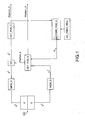
- a trajectory estimation system comprises an EC sensor assembly provided with an accelerometer A with at least one measuring axis and a gyrometer G with at least one measuring axis integrally linked.
- the system comprises a retroactivation module CORR_POS_A of an angular position Position_A of the gyrometer G among a plurality of successive instants, corresponding to the sampling instants on a time interval, from the Cartesian positions Position_C of the accelerometer A to at least two of said successive instants and predetermined information INF _PRED_TRAJ representative of the trajectory of the accelerometer A during the time interval [ t 1 ; t 2 ] by a rotation, which, applied to the trajectory, allows it to better check said predetermined information, ie to minimize a difference between said predetermined information INF_PRED_TRAJ and their equivalent on the trajectory obtained after rotation.
- a model of rotary registration of the trajectory obtained using the measurements of the accelerometer A so that it corresponds as best as possible to the predetermined information (ie the prior knowledge expressed in the form of parameters predetermined) of this trajectory) is inverted to find the rotation parameters of this rotary registration, these rotation parameters being then used to correct the angular position Position_A above.
- the time interval is delimited by a first terminal t 1 and a second terminal later t 2 .
- Samples over the time interval [ t 1 ; t 2 ] are indexed t l so that l varies between 1 and N, and t 1 is t 1 , and t N is t 2 .
- We define the trajectory as the set of Cartesian positions Position_C successive.
- the terminals t 1 and t 2 may correspond to two successive instants of zero velocity of one foot delimiting a phase between two instants of zero velocity of a foot or "MidStance" in English language.
- the system further comprises a memory module MEM_A of first measurements a b delivered by the accelerometer A, and a memory module MEM_G of second measurements ⁇ b delivered by the gyrometer G to said plurality of successive instants of said interval of time, in a movable reference BF linked to the EC sensor assembly.
- a first determination module DET_POS_A determines the angular position Position_A of the gyrometer G defined by angles or a quaternion representing the rotation making it possible to go from the NF mark to the BF mark successive instant audits t 1 , t 2 , ... t N-1 t N , from the second measurements ⁇ b .
- a second determination module DET_POS_C determines the Cartesian position Position_C of the accelerometer A, in the fixed overall reference NF, at said successive instants t 1 , t 2 , ... t N-1 , t N , from the first measurements a b and the angular position Position_A provided by the first determination module DET_POS_A, after a reference change made by a reference change module CR to go from the local reference BF to the NF mark (because after iterations, NF 'tends to confuse with NF, as described later in the description).
- the retroactive correction module CORR_POS_A is adapted to iteratively correct the angular position Position_A.
- the correction can be applied either at angular velocities (ie before an integration of the measurements of the gyrometer G, or applied at angles (ie after an integration of the measurements of the gyrometer G)
- the retroactive correction module CORR_POS_A is, furthermore, adapted to correct the Cartesian position Position_C to at least one of said successive instants t 1 , t 2 , ... t N-1 , t N.
- the predetermined information INF_PRED_TRAJ may comprise a substantially planar trajectory information of the accelerometer between a first instant and a second different instant, among said successive instants t 1 , t 2 , ... t N-1 , t N of said time interval [ t 1 ; t 2 ].
- the orientation of the plane around which the points of the trajectory are located can be known relative to the vertical or to the north.
- the path between said first and second instants may comprise a known heading and / or a known slope.
- the first and second instants may be the limits of the time interval.
- the predetermined information INF_PRED_TRAJ can include possible Cartesian positions stored, that is to say the Cartesian coordinates of points considered a priori as being part of the trajectory.
- the system can be adapted to be attached to a user, a mobile terminal, or a land, air or sea vehicle.
- a mobile terminal or a land, air or sea vehicle.
- fastening means near a user's ankle.
- An originality of the present invention comes from the fact that from knowledge on the trajectory (the trajectory is defined by the set of Cartesian positions between two given instants), the rotation is determined which, by turning the trajectory, makes it possible to satisfy the knowledge on the trajectory, to come correct the orientation or angular position Position_A by making use of this rotation then to recalculate the trajectory.
- correction is applied on a given time window.
- correction approach can be iterative.
- This correction Pos_A_C is distributed, in a predetermined way to define, for example linearly, by a division equirepart of the correction by dividing by the number of samples N, on attitudes or positions Position_A angular positions determined from the gyro measurements. Then the trajectory is recalculated.
- IMUs inertial measurement units
- the EC sensor assembly is attached to the movable body.
- the measurement of the instantaneous rotation vector is a necessity because of changes in attitude or angular position of the EC sensor assembly over time.
- the North reference or fixed global reference, or NF for "North Frame” in English is a fixed reference with respect to the terrestrial reference. It is used throughout the movement (walk or run).
- the North NF mark can be considered as the reference mark: the orientations or angular positions and the positions or positions Cartesian are measured in this reference.
- the fixed global coordinate system NF is defined by its origin O NF and its axes ( x NF , y NF , z NF ).
- the axes refer to the terrestrial landmark by the directions East, North, and High.
- Its origin O NF may be where the movement begins or at any other location.
- the data expressed in this frame are noted with an exponent n.
- the local or sensor-related benchmark or BF for "Body Frame” in English is the repository of the EC sensor assembly in which the raw data is measured. Its center is O BF . The data in this frame are noted with an exponent b. Its axes ( x BF , y BF , z BF ) correspond to the axes of the sensors (in the case of triaxial sensors) at each instant. The coordinates of its origin O BF in the fixed overall reference NF correspond to the location of the sensor in the fixed overall reference NF.
- an intermediate marker or SF for "Step Frame” in English is defined.
- the intermediate marker SF is a reference linked to the Earth, but only during a time interval [ t 1 , t 2 ] (for example during a step).
- This marker is used for movements with less than six degrees of freedom or six DOFs for "Degrees of Freedom” in English. For example, it is used when the sensor assembly EC has an invariant axis of rotation and / or a plane movement during the time interval [ t 1 , t 2 ] .
- the NF mark is a reference close to the NF mark which takes into account the drift due to the integration of the gyrometer. Assuming this zero drift NF and NF 'are merged. Otherwise, the NF 'mark is defined by the axes ( x NF' , y BF , z BF ) and the center O BF .
- the reference NF ' is the reference relative to which are expressed before correction the position_A angular position obtained by integrating the gyro and the cartesian position Position_C estimated double integrating the own acceleration.
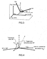
- the figure 3 represents the fixed global NF and local BF benchmarks.
- the local coordinate system BF is linked to the fixed global coordinate system NF by a translation and a rotation.
- all quaternions are, for example, unit quaternions.
- the accelerometer measures the sum of the accelerations applied to the sensor.
- the accelerometer measures, in addition to Earth's gravity, the proper acceleration experienced by the sensor.
- the proper acceleration at p is defined as the external acceleration experienced by the sensor, which is equal to the time derivative of the sensor speed.
- the gyro provides measurements for determining a quaternion of orientation.
- q bn ( t ) [ q bn , 0 ( t ) q bn, 1 ( t ) q bn, 2 ( t ) q bn , 3 ( t )] T the time-varying quaternion describing the orientation of the benchmark local BF relative to the fixed global reference NF.
- the first determination module DET_POS_A of the angular position Position_A of the gyrometer G integrates the differential equation (6) from q bn (0), where q bn (0) . corresponds to the initial orientation.
- equation (6) (or its discretized version) leads to a corrupt estimate of the attitude quaternion, and thus of the attitude or angular position.
- the orientation drift is generally expressed as an erroneous orientation of the local coordinate system BF. Since the main orientation problem is to make a reference change to express the acceleration data of the local coordinate system BF to the fixed global coordinate system NF, it is considered that an erroneous quaternion q nb does not allow a reference change of the local coordinate system. BF at the NF fixed global coordinate system, but at the NF 'mark having drifted, ie turned progressively. Consequently, NF 'is defined as a reference deviated from the fixed overall reference NF; it is described by its orientation relative to the fixed overall reference NF given by the quaternion q n'n .
- Is t 1 ⁇ t 2 the time interval of the SW phase of movement or flight of the foot (foot in the air) of the stride of the detection step number ⁇ (corresponding to the number ⁇ step ). It is assumed that q n'n ( t ) is invariant in time during each flight phase SW for t ⁇ t 1 ⁇ t 2 ⁇ .
- Another problem is the drift of the position because of the double temporal integration of the acceleration measurements.
- the acceleration is integrated only during the flight phase SW, while during the remaining time, the speed is set to zero.
- step detection methods it is possible to determine whether the foot is moving or not.
- the speed of a pedestrian's ankle is calculated step by step, while the orientation is determined continuously at the index of time I with the quaternion q bn' l
- This step is performed by the CR index change module.
- the main problem is that the vertical direction of the NF mark is different from that of the fixed overall mark NF.
- the acceleration is integrated twice, separately for each step, in order to calculate, after all, the complete trajectory of the ankle.
- v I not t v I not t 1 ⁇ + ⁇ t 1 ⁇ t ⁇ at p not t d t
- the calculated position may still be subject to drift because of qn ( t ).
- trajectory of the ankle is included in a plane (plane movement). Assuming that the plane of the trajectory of the true step (plane of the march) is vertical, then any orientation drift would incline the vertical plane.
- the figure 4 illustrates the case of a trajectory drift (for a step) and the corresponding trajectory that we suppose to be the "real trajectory” or "true".
- the quaternion q ⁇ vs corrects the trajectory of the step. It is thus strictly speaking the application of a model of rotary registration of the trajectory as calculated during the steps corresponding to the relations (14) to (17) under the constraint of a priori knowledge on this trajectory constituted by the hypotheses preceding.
- the orientation drift can be represented by the rotation matrix R c or equivalently, with the quaternion q ⁇ vs .
- the rotation matrix R c or equivalently, with the quaternion q ⁇ vs .
- the calculated trajectory can be rotated so as to have a predefined inclination displacement, for example horizontal.
- a predefined inclination displacement for example horizontal.
- qn ( t ) is invariant in time for short durations, more precisely during the flight phase of each step.
- An object of the invention is to calculate the corrected orientation q bn + l by applying a correction q l
- the ⁇ ⁇ vs linearly varying over time at the calculated orientation (in this case the correction increases linearly over time), so as to compensate for the drift of q bn' l by applying the following relation: q b not + l q b not ' l ⁇ q - l
- the ⁇ ⁇ vs for l ⁇ l 2 ⁇ - 1 : l 2 ⁇ in which : q b not ' l q - ⁇ b l ⁇ ...
- The q ⁇ vs ⁇ q bn' The , which is equivalent to q bn +
- The q bn' The ⁇ q - ⁇ vs .
- the trajectory is recalculated from the corrected orientation q bn + .
- the Figures 7a, 7b, and 7c represent the three-dimensional or 3D trajectory of the pedestrian's ankle.
- the correction is made with the first assumption of constant angle between NF and NF '(by equation (24) and the previous ones) and on the Figure 7c , the correction is made with the second hypothesis of linear variation of the angle between NF and NF '.
- the proposed corrections guarantee the constraints, as illustrated by the Figures 7b and 7c .
- Figures 8a and 8b respectively show the same trajectories as those of Figures 6b and 6c in the horizontal plane. In this case, the directions of displacement with respect to North ⁇ b and ⁇ b are biased, but we can notice on that the correction of orientation with the second hypothesis clearly reduces this drift .
Description
L'invention porte sur un système d'estimation d'une trajectoire d'un élément ou d'un corps mobile comprenant un ensemble capteur comprenant un accéléromètre et un gyromètre liés de manière solidaire.The invention relates to a system for estimating a trajectory of a mobile element or body comprising a sensor assembly comprising an accelerometer and a gyrometer bound together.
La trajectoire d'un élément est un ensemble de positions cartésiennes Position_C successives de l'élément.The trajectory of an element is a set of successive Cartesian positions Position_C of the element.
L'invention concerne notamment l'estimation de cette trajectoire ou de l'orientation dans le cadre de la navigation piéton. Ce domaine est en pleine expansion, avec au moins une conférence internationale intégralement dédiée au domaine de la navigation et de la localisation à l'intérieur des bâtiments (International Conference on Indoor Positionning and Indoor Navigation - IPIN, articles publiés dans IEEE Xplore).The invention particularly relates to the estimation of this trajectory or orientation in the context of pedestrian navigation. This field is in full expansion, with at least one international conference fully dedicated to the field of navigation and location within buildings (International Conference on Indoor Positioning and Indoor Navigation - IPIN, articles published in IEEE Xplore).
L'invention se situe dans un contexte à deux modalités de mesure, à savoir accéléromètres et gyromètres (AG).The invention lies in a context with two measurement modes, namely accelerometers and gyrometers (AG).
Sans un système externe permettant de déterminer la direction du Nord ou un magnétomètre pour mesurer le champ magnétique terrestre, il n'est pas possible de garantir que le repère de référence soit le repère Nord pour "North Frame" en langue anglaise, qui est un repère fixe dans le référentiel terrestre. Ce repère est utilisé durant tout le mouvement (marche ou course). Il est considéré comme le repère de référence : les orientations (position angulaire) et positions (position cartésienne) sont mesurées par rapport à ce repère.Without an external system for determining the direction of the North or a magnetometer for measuring the Earth's magnetic field, it is not possible to guarantee that the reference mark is the North mark for "North Frame" in English, which is a fixed landmark in the land referential. This marker is used throughout the movement (walk or run). It is considered as the reference mark: the orientations (angular position) and positions (Cartesian position) are measured with respect to this reference.
Le repère Nord est défini par son origine ONF et ses axes (xNF , YNF , ZNF ) qui se confondent avec les axes du repère terrestre, de directions l'Est, le Nord et la verticale ascendante. Son origine ONF peut correspondre à l'endroit où le mouvement débute ou à tout autre endroit.The North coordinate system is defined by its origin O NF and its axes ( x NF , Y NF , Z NF ) which merge with the axes of the terrestrial reference, from east, north and vertical ascending. Its origin O NF may correspond to the place where the movement begins or to any other place.
Par conséquent, dans cette partie, nous nous référons au repère de navigation NF, qui est lié au repère Nord par une rotation constante autour de l'axe vertical. Dans la suite de la description, le repère de navigation NF est utilisé comme repère de référence, et les mesures données dans ce repère de navigation NF ont un exposant n.Therefore, in this part, we refer to the NF navigation mark, which is linked to the North mark by a constant rotation around the vertical axis. In the remainder of the description, the NF navigation mark is used as a reference mark, and the measurements given in this NF navigation mark have an exponent n.
La trajectoire parcourue par l'ensemble capteur EC peut être récupérée par une double intégration de l'accélération propre ![]()
![]()
Soit le repère BF un repère lié au capteur. Dans la suite, les vecteurs exprimés dans ce repère ont un exposant b. Les mesures de l'accéléromètre..sont données dans le repère BF et la gravité (ou pesanteur) est superposée à l'accélération propre ![]()
![]()
Avant de réaliser la double intégration il est donc nécessaire d'exprimer les mesures dans le repère NF et de compenser la gravité.Before carrying out the double integration, it is therefore necessary to express the measurements in the NF mark and to compensate for the gravity.
Pour réaliser le passage du repère NF au repère BF, une formule de passage est nécessaire. Cette formule peut être obtenue si on connaît l'orientation du capteur. Dans le contexte AG, l'orientation est obtenue en intégrant la mesure du gyromètre. Cependant, cette intégration génère une dérive que nous proposons de limiter dans la présente invention.To make the transition from the NF mark to the BF mark, a passage formula is necessary. This formula can be obtained if we know the orientation of the sensor. In the context AG, the orientation is obtained by integrating the measurement of the gyrometer. However, this integration generates a drift that we propose to limit in the present invention.
Dans la littérature, la dérive d'orientation est généralement exprimée comme une erreur d'orientation du repère local BF par rapport au repère NF. On peut alors considérer qu'une erreur ou dérive de l'orientation estimée tourne les données du repère local BF, non pas vers le repère de navigation NF, mais vers un autre repère de navigation NF' affecté par la dérive et défini dans la suite de la description.In the literature, the orientation drift is generally expressed as an orientation error of the local coordinate system BF with respect to the NF mark. It can then be considered that an error or drift of the estimated orientation turns the data of the local coordinate system BF, not to the navigation mark NF, but to another navigation mark NF 'affected by the drift and defined in the following of the description.
Le repère NF', affecté par la dérive est défini par son orientation par rapport au repère de navigation ou repère global fixe lié au repère terrestre NF. Cette orientation de NF' par rapport à NF, est liée à la dérive de l'orientation estimée en intégrant le gyromètre. Ainsi, l'orientation du repère NF' par rapport au repère NF dérive lentement au fil du temps. Les mesures données dans ce repère NF' ont un exposant n'.The reference NF 'affected by the drift is defined by its orientation relative to the navigation mark or fixed global reference linked to the terrestrial reference NF. This orientation of NF 'with respect to NF is related to the drift of the estimated orientation by integrating the gyrometer. Thus, the orientation of the reference NF 'relative to the NF mark drift slowly over time. The measurements given in this reference NF 'have an exponent n'.
Si on représente l'orientation du repère NF dans le repère NF' par un quaternion qn'n , l'orientation du repère NF dans le repère BF par un quaternion qbn, l'orientation du repère NF' dans le repère BF par un quaternion qbn' , on peut alors écrire par l'équation suivante : ![]()
![]()
Dans une approche classique, il est possible d'estimer la trajectoire d'une cheville d'un utilisateur à partir des données inertielles mesurées par l'accéléromètre et le gyromètre.In a conventional approach, it is possible to estimate the trajectory of a user's ankle from the inertial data measured by the accelerometer and the gyrometer.
Dans ce cas, (au niveau de la cheville), le cycle de marche peut être séparé en deux phases: la phase de vol pendant laquelle le pied se déplace (appelée SW pour "SWing phase" en langue anglaise), et celle pendant laquelle le pied est au sol ou phase d'appui (appelée ST pour "STance phase" en langue anglaise). Un pas est composé de la succession des deux phases ST et SW et la marche est caractérisée par une succession de pas.In this case, (at the ankle), the walking cycle can be separated into two phases: the flight phase during which the foot moves (called SW for "SWing phase" in English), and that during which the foot is on the ground or support phase (called ST for "STance phase" in English). A step is composed of the succession of the two phases ST and SW and the walk is characterized by a succession of steps.
On nomme ![]()
![]()
La vitesse de la cheville d'un piéton peut être calculée pas par pas (après exécution d'une étape de détection), tandis que l'orientation ou position angulaire Position_A est déterminée à chaque indice de temps l avec le quaternion ![]()
![]()
![]()
![]()
![]()
![]()
![]()
![]()
Une fois que l'orientation dans le repère local BF est déterminée, les mesures de l'accéléromètre sont simplement tournées par rotation dans le repère global NF, par la relation ![]()
![]()
![]()

![]()
![]()
![]()
Quand la mesure de l'accéléromètre dans le repère NF a n a été calculée, la gravité doit être compensée pour calculer l'accélération propre : ![]()
![]()
En fait, le quaternion de positition angulaire ![]()
![]()
![]()
![]()
![]()
![]()
Les mesures de l'accéléromètre, et ainsi même l'accélération propre ![]()
![]()
Même si l'accélération propre est calculée avec un quaternion de position angulaire ![]()
![]()
En outre, en raison de la dérive du quaternion ![]()
![]()
Le thème de la navigation et de la localisation dans des bâtiments, i.e. en intérieur ou "indoor" en langue anglaise, est un problème classique rencontré dans la littérature. En 2010, une conférence intégralement dédiée à la navigation et au positionnement indoor a été créée (IPIN pour "International Conference on Indoor Positioning and Indoor Navigation", IEEE). Parmi les articles présentés, neuf sont consacrés à la navigation piéton avec un système de capture de mouvement fixé au pied ou "foot mounted pedestrian navigation" en langue anglaise. Ci-suit un résumé de ces communications ainsi que d'autres communications.The theme of navigation and location in buildings, i.e. indoor or "indoor" in English, is a classic problem encountered in the literature. In 2010, a conference dedicated entirely to navigation and indoor positioning was created (IPIN for "International Conference on Indoor Positioning and Indoor Navigation", IEEE). Among the items presented, nine are devoted to pedestrian navigation with a foot-mounted motion capture system or "foot mounted pedestrian navigation" in English. The following is a summary of these and other communications.
Un premier article, "A High Precision Reference Data Set for Pedestrian Navigation using Foot-Mounted Inertial Sensors", de Michael Angermann, Patrick Robertson, Thomas Kemptner, et Mohammed Khider, IPIN conference, Zurich, 2010, présente une méthodologie d'aquisition de données basée sur un système optique de référence et une unité de mesures inertielles fixée au pied, le problème de l'estimation de la trajectoire n'étant pas abordé.A first article, Michael Angermann, Patrick Robertson, Thomas Kemptner, and Mohammed Khider, IPIN Conference, Zurich, 2010, "A High Precision Reference Data Set for Foot Navigation Using Foot-Mounted Inertial Sensors", presents a methodology for the acquisition of data based on a reference optical system and a unit of inertial measurements fixed to the foot, the problem of the estimation of the trajectory not being addressed.
Un deuxième article, "Evaluation of Zero-Velocity Detectors for Foot-Mounted Inertial avigation Systems", de Isaac Skog, John-Olof Nilsson, et Peter Händel, IPIN conference, Zurich, 2010, s'intéresse au problème de la détection des phases de mouvement à vitesse nulle pour un pied équipé d'une centrale inertielle ("zero velocity detectors for a footmounted inertial sensor based pedestrian navigation system"). Quatre techniques de détection de vitesse nulle sont comparées sur le critère d'erreur de position. Le problème de dérive de position induit par les décalages et dérives des mesures n'est pas abordé.A second article, Isaac Skog's John-Olof Nilsson's "Evaluation of Zero-Velocity Detectors for Foot-Mounted Inertial Avigation Systems," and Peter Händel, IPIN conference, Zurich, 2010, focus on the problem of phase detection. zero-speed movement for a foot equipped with an inertial unit ("zero velocity detectors for a footmounted inertial sensor based pedestrian navigation Four velocity detection techniques are compared on the error of position criterion The problem of position drift induced by the shifts and drifts of the measurements is not addressed.
Un troisième article, "
Un quatrième article, "
Un sixième article, "
Un septième article, "
Dans un huitième article, "
Un neuvième article, "
Un dixième article, "
Un onzième article, "
D'autres articles, tel un douzième article, "
Pour résumer ces treize articles précédents, soit ils mettent en oeuvre un système complémentaire à la centrale inertielle (y compris carte, GPS, UWB) pour compenser la dérive en position, soit ils implantent un filtre de Kalman (IKF, EKF), soit ils exploitent explicitement des mesures fournies par des magnétomètres.To summarize these thirteen previous articles, they implement a complementary system to the inertial unit (including map, GPS, UWB) to compensate for drift in position, or they implement a Kalman filter (IKF, EKF), or they Explicitly exploit measurements provided by magnetometers.
Le document
Le document
Le document
Le brevet
Un quatorzième article "
Un quinzième article,
Un seizième article, "
Un dix-septième article, "
Un dix-huitième article "
Un dix-neuvième article, "
Ces différents systèmes ont une précision limitée et un coût élevé. Ils ne proposent pas de résoudre le problème de la dérive de l'orientation de manière globale en tenant compte d'informations sur la trajectoire. Ils nécessitent souvent un nombre de capteurs supérieur à celui de la présente invention.These different systems have limited accuracy and high cost. They do not propose to solve the problem of orientation drift in a global manner by taking into account information on the trajectory. They often require a higher number of sensors than that of the present invention.
Il est proposé, selon un aspect de l'invention, un système d'estimation de trajectoire d'un élément ou d'un corps mobile, comprenant un ensemble capteur comprenant un accéléromètre et un gyromètre liés de manière solidaire. Le système comprend des moyens de correction rétroactive d'une position angulaire obtenue à partir des mesures du gyromètre à au moins un instant parmi une pluralité d'instants successifs d'un intervalle de temps à partir de positions cartésiennes de l'accéléromètre à au moins deux desdits instants successifs et d'informations prédéterminées représentatives de la trajectoire de l'accéléromètre durant ledit intervalle de temps, et à partir d'une rotation adaptée pour minimiser un écart entre lesdites informations prédéterminées et leur équivalent sur la trajectoire obtenue après rotation.According to one aspect of the invention, there is provided a system for estimating the trajectory of a mobile element or body, comprising a sensor assembly comprising an accelerometer and a gyrometer linked together. The system comprises means for retroactively correcting an angular position obtained from the gyro measurements at least one of a plurality of successive instants of a time interval from Cartesian positions of the accelerometer to at least one two of said successive instants and predetermined information representative of the trajectory of the accelerometer during said time interval, and from a rotation adapted to minimize a difference between said predetermined information and their equivalent on the trajectory obtained after rotation.
Les informations prédéterminées peuvent être relatives à l'orientation de la trajectoire. Cette orientation peut être calculée à partir de la trajectoire estimée. Par exemple, si l'information prédéterminée est l'orientation de la direction du pas par rapport au Nord (ou cap de la marche), alors son équivalent sur la trajectoire est calculé par exemple en prenant l'angle entre la direction Nord-Sud et la projection sur le plan horizontal du vecteur reliant le premier et le dernier point de la trajectoire du pas.The predetermined information may relate to the orientation of the trajectory. This orientation can be calculated from the estimated trajectory. For example, if the predetermined information is the orientation of the direction of pitch relative to the North (or heading of the march), then its equivalent on the trajectory is calculated for example by taking the angle between the North-South direction and the projection on the horizontal plane of the vector connecting the first and the last point of the path of the step.
Un tel système permet de compenser la dérive en agissant sur les angles estimés en intégrant les mesures du gyromètre à partir de la trajectoire obtenue. Cela permet de gérer le problème de la dérive de manière globale.Such a system makes it possible to compensate the drift by acting on the estimated angles by integrating the measurements of the gyrometer from the trajectory obtained. This makes it possible to manage the problem of drift in a global way.
En outre, l'objet de la présente invention est d'obtenir une correction de trajectoire sans utiliser des données de mesure issues du magnétomètre. La correction est basée uniquement sur les mesures issues de l'accéléromètre et du gyromètre.In addition, the object of the present invention is to obtain a trajectory correction without using measurement data from the magnetometer. The correction is based solely on the measurements from the accelerometer and the gyrometer.
Dans la présente invention, l'attitude du repère mobile est obtenu via l'intégration numérique des mesures gyrométriques, et la dérive est compensée non sur les mesures accélérométriques, mais sur l'attitude estimée, en tenant compte d'hypothèses sur la trajectoire, telle que par exemple, le déplacement du piéton dans un plan horizontal.In the present invention, the attitude of the moving marker is obtained via the numerical integration of the gyrometric measurements, and the drift is compensated not on the accelerometric measurements, but on the estimated attitude, taking into account hypotheses on the trajectory, such as, for example, the movement of the pedestrian in a horizontal plane.
L'intervalle de temps peut correspondre à une phase de vol d'un pied.The time interval may correspond to a flight phase of a foot.
Dans un mode de réalisation, le système comprend, en outre :
- des moyens de mémorisation de premières mesures délivrées par l'accéléromètre et de deuxièmes mesures délivrées par le gyromètre à ladite pluralité d'instants successifs dudit intervalle de temps, dans un repère mobile lié à l'ensemble capteur ;
- des premiers moyens de détermination de ladite position angulaire du gyromètre définie par des angles de rotation par rapport à des positions de référence selon les axes d'un repère global fixe lié au repère terrestre, audits instants successifs, à partir desdites deuxièmes mesures ; et
- des deuxièmes moyens de détermination de ladite position cartésienne de l'accéléromètre, dans ledit repère global fixe, auxdits instants successifs, à partir desdites premières mesures et de ladite position angulaire fournie par lesdits premiers moyens de détermination.
- means for storing first measurements delivered by the accelerometer and second measurements delivered by the gyrometer at said plurality of successive instants of said time interval, in a movable reference linked to the sensor assembly;
- first means for determining said angular position of the gyrometer defined by angles of rotation relative to reference positions along the axes of a fixed global reference linked to the terrestrial reference, successive instants audits, from said second measurements; and
- second means for determining said Cartesian position of the accelerometer, in said fixed overall reference, at said successive instants, from said first measurements and said angular position provided by said first determination means.
Ainsi, la trajectoire peut être obtenue et la dérive en position peut être corrigée.Thus, the trajectory can be obtained and the drift in position can be corrected.
Plus particulièrement, le système de l'invention est apte à estimer une trajectoire d'un élément ou d'un corps mobile, en utilisant :
- l'accéléromètre apte à délivrer des mesurés de données, le gyromètre apte à délivrer des mesures de vitesses angulaires,
- des premiers moyens d'estimation de la position angulaire à partir de la vitesse angulaire mesurée par le gyromètre, à au moins deux instants parmi une pluralité d'instants successifs d'un intervalle de temps,
- des deuxièmes moyens d'estimation de la trajectoire de l'élément ou du corps mobile comprenant, à au moins deux desdits instants successifs, une position cartésienne de l'accéléromètre, à partir des mesurés de cet accéléromètre, et à partir de la position angulaire précédemment estimée, et
- des troisièmes moyens d'estimation d'une rotation adaptée pour minimiser un écart entre des informations prédéterminées représentatives de la trajectoire à estimer et leur équivalent sur la trajectoire tournée, obtenue après rotation de la trajectoire précédemment estimée,
- des moyens de correction rétroactive de la position angulaire auxdits au moins deux instants estimée par les premiers moyens d'estimation, à partir des résultats de la rotation estimée par les troisièmes moyens d'estimation,
- des quatrièmes moyens d'estimation de la trajectoire corrigée de l'élément ou du corps mobile comprenant une position cartésienne corrigée de l'accéléromètre à au moins deux desdits instants successifs, à partir des mesures de cet accéléromètre, et à partir de la position angulaire corrigée.
- the accelerometer capable of delivering measured data, the gyro capable of delivering measurements of angular velocities,
- first means for estimating the angular position from the angular velocity measured by the gyro, at at least two instants from a plurality of successive instants of a time interval,
- second means for estimating the trajectory of the element or the moving body comprising, at least two of said successive instants, a Cartesian position of the accelerometer, from the measured values of this accelerometer, and from the angular position previously estimated, and
- third means for estimating a rotation adapted to minimize a difference between predetermined information representative of the trajectory to be estimated and their equivalent on the rotated trajectory, obtained after rotation of the trajectory previously estimated,
- means for retroactively correcting the angular position at said at least two instants estimated by the first estimation means, on the basis of the results of the rotation estimated by the third estimation means,
- fourth means for estimating the corrected trajectory of the element or of the moving body comprising a corrected Cartesian position of the accelerometer at at least two of said successive instants, from the measurements of this accelerometer, and from the angular position corrected.
Selon un mode de réalisation, lesdits moyens de correction sont adaptés pour corriger itérativement ladite position angulaire.According to one embodiment, said correction means are adapted to iteratively correct said angular position.
Ainsi, la précision est améliorée.Thus, the accuracy is improved.
Dans un mode de réalisation, lesdites informations prédéterminées représentatives de la trajectoire de l'accéléromètre comprennent une trajectoire sensiblement planaire de l'accéléromètre entre un premier instant et un deuxième instant différents, parmi lesdits instants successifs dudit intervalle de temps.In one embodiment, said predetermined information representative of the trajectory of the accelerometer comprises a substantially planar trajectory of the accelerometer between a first instant and a second instant, among said successive instants of said time interval.
Ainsi, est prise en compte, une caractéristique communément rencontrée dans les mouvements, notamment humains ou animaux ou robots, et ainsi la précision est améliorée.Thus, is taken into account, a characteristic commonly encountered in movements, including humans or animals or robots, and thus the accuracy is improved.
Par exemple le mouvement d'une cheville durant la marche est sensiblement planaire.For example the movement of an ankle during walking is substantially planar.
Dans un mode de réalisation, l'orientation du plan de la trajectoire est connue par rapport à la verticale ou au nord.In one embodiment, the orientation of the plane of the trajectory is known relative to the vertical or to the north.
Ainsi, la précision est améliorée.Thus, the accuracy is improved.
Selon un mode de réalisation, la trajectoire entre lesdits premier et deuxième instants comprend un cap connu et/ou une pente connue.According to one embodiment, the trajectory between said first and second instants comprises a known heading and / or a known slope.
Ainsi, il est possible de prendre en compte des informations mémorisées concernant la pente du lieu où se trouve l'utilisateur ou le cap du déplacement (lors d'un déplacement dans un couloir par exemple), pour lesquels la position angulaire revient régulièrement à la même valeur.Thus, it is possible to take into account stored information relating to the slope of the location where the user is or the course of movement (during a movement in a corridor for example), for which the angular position regularly returns to the same value.
Dans un mode de réalisation, lesdits premier et deuxième instants sont les bornes dudit intervalle de temps.In one embodiment, said first and second instants are the boundaries of said time interval.
Ainsi, dans le cas de mouvements cycliques, l'intervalle de temps correspond à un cycle ou à une partie du cycle (par exemple, dans le cas de la marche, l'intervalle de temps correspond à la phase séparant deux instants successifs de vitesse nulle d'un pied).Thus, in the case of cyclic movements, the time interval corresponds to a cycle or part of the cycle (for example, in the case of walking, the time interval corresponds to the phase separating two successive instants of speed zero of one foot).
Par ailleurs, si l'intervalle de temps correspond à une phase de mouvement encadrée par deux phases d'immobilité (ou "MidStance" en langue anglaise dans le cas de la marche) comme dans le cas de la marche, l'hypothèse de mouvement planaire concerne tout le mouvement durant un pas.Moreover, if the time interval corresponds to a movement phase framed by two phases of immobility (or "MidStance" in the English language in the case of walking) as in the case of walking, the motion hypothesis planar concerns all the movement during a step.
Selon un mode de réalisation, lesdites informations prédéterminées représentatives de la trajectoire de l'accéléromètre comprennent des positions cartésiennes possibles mémorisées.According to one embodiment, said predetermined information representative of the path of the accelerometer comprises possible Cartesian positions stored.
Ainsi, le calcul de la rotation de la trajectoire prend en compte ces points possibles de passage.Thus, the calculation of the rotation of the trajectory takes into account these possible points of passage.
Dans un mode de réalisation, lesdits moyens de correction rétroactive sont adaptés pour répartir de manière prédéterminée la correction sur tout ou partie de ladite pluralité d'instants successifs. Par exemple, la correction est linéaire, voire équirépartie.In one embodiment, said retroactive correction means are adapted to distribute the correction in a predetermined manner on all or part of said plurality of successive instants. For example, the correction is linear, even equidistributed.
Ainsi, la correction n'est pas la même à chaque instant et on peut tenir compte de l'évolution temporelle possible de la dérive.Thus, the correction is not the same at every moment and one can take into account the possible temporal evolution of the drift.
Par exemple, lesdits moyens de correction sont adaptés pour faire croître linéairement la correction sur tout ou partie de ladite pluralité d'instants successifs.For example, said correction means are adapted to linearly increase the correction on all or part of said plurality of successive instants.
Une répartition linéaire de la correction permet de ne pas avoir d'a priori sur les instants auxquels la correction doit être apportée, mais de tenir compte du fait que cette correction augmente au cours du temps ce qui est le cas lorsque le gyromètre possède un biais.A linear distribution of the correction makes it possible not to have a priori on the instants to which the correction must be made, but to take into account the fact that this correction increases over time which is the case when the gyrometer has a bias .
Dans un mode de réalisation, le système est adapté pour être fixé à un utilisateur, à un terminal mobile, ou à un véhicule terrestre, aérien ou maritime.In one embodiment, the system is adapted to be attached to a user, a mobile terminal, or a land, air or sea vehicle.
Un utilisateur peut être vivant (humain ou animal), ou artificiel.A user can be alive (human or animal), or artificial.
Ainsi, la trajectoire du lieu où est fixé le système peut être estimée.Thus, the trajectory of the place where the system is fixed can be estimated.
Selon un mode de réalisation, le système comprend des moyens de fixation à proximité d'une cheville d'un utilisateur.According to one embodiment, the system comprises fastening means near a peg of a user.
Il est également proposé, selon un autre aspect de l'invention, un procédé d'estimation de trajectoire d'un élément ou d'un corps mobile, dans lequel on corrige de manière rétroactive, une position angulaire, à partir des résultats des étapes successives suivantes consistant à :
- estimer une position angulaire obtenue à partir des mesures d'un gyromètre, à au moins un instant parmi une pluralité d'instants successifs d'un intervalle de temps,
- estimer une position cartésienne d'un accéléromètre lié de manière solidaire au gyromètre à au moins un desdits instants successifs à partir des mesures de l'accéléromètre, et d'informations prédéterminées représentatives de la trajectoire de l'accéléromètre durant ledit intervalle de temps, et
- estimer une rotation adaptée pour minimiser un écart entre lesdites informations prédéterminées et leur équivalent sur la trajectoire obtenue après rotation.
- estimating an angular position obtained from the measurements of a gyrometer, at least one moment among a plurality of successive instants of a time interval,
- estimating a Cartesian position of an accelerometer integrally linked to the gyrometer at at least one of said successive instants from measurements of the accelerometer, and of predetermined information representative of the trajectory of the accelerometer during said time interval, and
- estimating a rotation adapted to minimize a difference between said predetermined information and their equivalent on the trajectory obtained after rotation.
A cet effet, l'invention a pour objet un procédé d'estimation d'une trajectoire d'un élément ou corps mobile à l'aide d'un ensemble capteur, cet ensemble capteur étant fixé à l'élément ou corps mobile et comportant un accéléromètre et un gyromètre liés de manière solidaire, comportant les étapes suivantes :
- réception de valeurs d'accélération fournies par l'accéléromètre et mesurées à au moins deux instants parmi une pluralité d'instants successifs d'un intervalle de temps,
- réception de valeurs de vitesse angulaire fournies par le gyromètre et mesurées à au moins deux instants parmi ladite pluralité d'instants successifs de cet intervalle de temps,
- traitement des valeurs fournies pour l'estimation, d'une part, d'au moins une valeur de position angulaire à l'aide des valeurs de vitesse angulaire et, d'autre part, d'au moins deux valeurs de position cartésienne définissant une trajectoire de l'élément ou corps mobile à l'aide des valeurs d'accélération et de ladite au moins une valeur de position angulaire précédemment estimée,
- estimation de paramètres de rotation, par inversion d'un modèle de recalage rotatoire de la trajectoire estimée sous la contrainte d'une connaissance a priori de la trajectoire, cette connaissance a priori étant constituée de paramètres prédéterminés de cette trajectoire, et
- correction rétroactive de ladite au moins une valeur de position angulaire estimée, par application d'une rotation sur cette valeur à l'aide des paramètres de rotation estimés, de manière à fournir au moins une valeur de position angulaire corrigée.
- receiving acceleration values provided by the accelerometer and measured at least two of a plurality of successive times of a time interval,
- receiving angular velocity values provided by the gyro and measured at least two of said plurality of successive instants of said time interval,
- processing of the values provided for the estimation, on the one hand, of at least one angular position value by means of the angular velocity values and, on the other hand, of at least two Cartesian position values defining a path of the element or moving body using the acceleration values and said at least one previously estimated angular position value,
- estimation of rotation parameters, by inversion of a rotational registration model of the estimated trajectory under the constraint of a priori knowledge of the trajectory, this a priori knowledge consisting of predetermined parameters of this trajectory, and
- retroactively correcting said at least one estimated angular position value by applying a rotation thereof to said value using the estimated rotation parameters to provide at least one corrected angular position value.
De façon optionnelle, l'étape de correction rétroactive comporte en outre une correction rétroactive des valeurs de position cartésienne à l'aide des valeurs d'accélération et de ladite au moins une valeur de position angulaire corrigée.Optionally, the retroactive correction step further comprises a retroactive correction of the Cartesian position values using the acceleration values and said at least one corrected angular position value.
De façon optionnelle également :
- les valeurs d'accélération fournies par l'accéléromètre et les valeurs de vitesse angulaire fournies par le gyromètre sont exprimées dans un repère mobile lié à l'ensemble capteur, et
- lors de l'étape de traitement des valeurs fournies, l'estimation de ladite au moins une valeur de position angulaire est exprimée sous la forme de paramètres d'angles de rotation par rapport aux axes d'un repère global fixe lié au repère terrestre et l'estimation desdites valeurs de position cartésienne est exprimée sous la forme de coordonnées cartésiennes dans ce même repère global fixe.
- the acceleration values provided by the accelerometer and the angular velocity values provided by the gyrometer are expressed in a movable reference linked to the sensor assembly, and
- in the step of processing the values provided, the estimate of said at least one angular position value is expressed as parameters of angles of rotation with respect to the axes of a fixed global reference linked to the terrestrial reference and the estimation of said Cartesian position values is expressed in the form of Cartesian coordinates in the same fixed global coordinate system.
De façon optionnelle également, l'étape de correction rétroactive est réalisée en une pluralité d'itérations, pour une correction itérative de ladite au moins une valeur de position angulaire estimée.Also optionally, the retroactive correction step is performed in a plurality of iterations, for an iterative correction of said at least one estimated angular position value.
De façon optionnelle également, les paramètres de rotation sont ceux d'un quaternion.Also optionally, the rotation parameters are those of a quaternion.
De façon optionnelle également, la connaissance a priori de la trajectoire comporte des paramètres d'orientation angulaire, notamment par rapport à la verticale ou au nord, d'un plan considéré comme devant contenir la trajectoire.Also optionally, the a priori knowledge of the trajectory comprises angular orientation parameters, particularly with respect to the vertical or north, of a plane considered to contain the trajectory.
De façon optionnelle également, la connaissance a priori de la trajectoire comporte les coordonnées cartésiennes d'au moins deux points considérés comme devant faire partie de la trajectoire.Optionally also, the a priori knowledge of the trajectory comprises the Cartesian coordinates of at least two points considered to be part of the trajectory.
De façon optionnelle également, la connaissance a priori de la trajectoire comporte des paramètres de cap ou de pente de la trajectoire.Optionally also, the prior knowledge of the trajectory includes heading parameters or slope of the trajectory.
De façon optionnelle également, l'étape de correction rétroactive est conçue pour que la correction réalisée à l'aide des paramètres de rotation estimés soit répartie de manière prédéterminée sur tout ou partie de ladite pluralité d'instants successifs.Optionally also, the retroactive correction step is designed so that the correction performed using the estimated rotation parameters is distributed in a predetermined manner on all or part of said plurality of successive instants.
De façon optionnelle également, la répartition prédéterminée de la correction rétroactive est définie de manière à faire croître linéairement des paramètres de correction calculés à l'aide des paramètres de rotation estimés sur tout ou partie de ladite pluralité d'instants successifs.Optionally also, the predetermined distribution of the retroactive correction is defined so as to linearly increase correction parameters calculated using the rotation parameters estimated on all or part of said plurality of successive instants.
L'invention a également pour objet un programme d'ordinateur téléchargeable depuis un réseau de communication et/ou enregistré sur un support lisible par ordinateur et/ou exécutable par un processeur, comprenant des instructions pour l'exécution des étapes d'un procédé d'estimation d'une trajectoire selon l'invention, lorsque ledit programme est exécuté sur un ordinateur.The invention also relates to a computer program downloadable from a communication network and / or recorded on a computer readable medium and / or executable by a processor, comprising instructions for performing the steps of a method of estimation of a trajectory according to the invention, when said program is executed on a computer.
Enfin, l'invention a également pour objet un système d'estimation d'une trajectoire d'un élément ou corps mobile, comportant :
- un accéléromètre apte à fournir des valeurs d'accélération mesurées à des instants successifs d'un intervalle de temps donné,
- un gyromètre lié de manière solidaire à l'accéléromètre, apte à fournir des valeurs de vitesse angulaire mesurées à des instants successifs de cet intervalle de temps, et
- des moyens de traitement des valeurs fournies par l'accéléromètre et le gyromètre conçus pour la mise en oeuvre d'un procédé d'estimation d'une trajectoire selon l'invention.
- an accelerometer capable of supplying acceleration values measured at successive instants of a given time interval,
- a gyrometer linked integrally with the accelerometer, able to provide angular velocity values measured at successive times of this time interval, and
- means for processing the values provided by the accelerometer and the gyrometer designed for the implementation of a trajectory estimation method according to the invention.
De façon optionnelle, un tel système d'estimation d'une trajectoire peut comporter des moyens de fixation solidaire de l'accéléromètre et du gyromètre a un utilisateur, par exemple à la cheville de cet utilisateur, à un terminal mobile ou à un véhicule terrestre, aérien ou maritime.Optionally, such a trajectory estimation system may comprise means for securing the accelerometer and the gyrometer to a user, for example at the user's ankle, at a mobile terminal or at a land vehicle. , air or sea.
L'invention sera mieux comprise à l'étude de quelques modes de réalisation décrits à titre d'exemples nullement limitatifs et illustrés par les dessins annexés sur lesquels :
- la
figure 1 illustre un mode de réalisation d'un système selon un aspect de l'invention ; - les
figures 2a et 2b illustrent un exemple liée à la marche d'un piéton ; - la
figure 3 représente les repères global fixe NF et local BF ; - la
figure 4 illustre les trajectoires dans les repères global fixe NF et NF'; - la
figure 5 illustre la correction rétroactive de l'orientation ou position angulaire ; - les
figures 6a, 6b et 6c illustrent les trajectoires estimées sans corriger la dérive (6a), en faisant une correction rétroactive de la dérive mais en appliquant une correction angulaire constante pendant la durée de chaque pas (6b), et en faisant une correction récursive et une correction angulaire rétroactive linéaire (6c) ; et - les
figures 7a et 7b illustrent les projections sur le plan horizontal des trajectoires desfigures 6b et 6c : les courbes en trait gras représentent un aller et retour estimé, les courbes en traits fins représentent le trajet réellement réalisé.
- the
figure 1 illustrates an embodiment of a system according to one aspect of the invention; - the
Figures 2a and 2b illustrate an example related to walking a pedestrian; - the
figure 3 represents the NF and local BF fixed global benchmarks; - the
figure 4 illustrates the trajectories in the fixed global reference marks NF and NF '; - the
figure 5 illustrates the retroactive correction of the orientation or angular position; - the
Figures 6a, 6b and 6c illustrate the estimated trajectories without correcting the drift (6a), making a retroactive correction of the drift but applying a constant angular correction during the duration of each step (6b), and making a recursive correction and a linear retroactive angular correction ( 6c); and - the
Figures 7a and 7b illustrate the horizontal projections of the trajectories of theFigures 6b and 6c : the curves in bold lines represent an estimated round trip, the curves in fine lines represent the path actually achieved.
Dans l'ensemble des figures, les éléments ayants les mêmes références sont similaires.In all the figures, the elements having the same references are similar.
La présente invention propose, dès qu'un pas est détecté (grâce à un algorithme de détection de pas qui permet de déterminer le début et la fin d'un pas), d'intégrer les mesures du gyromètre pour déterminer une estimation de l'orientation, de ramener les mesures de l'accéléromètre dans le repère inertiel, de compenser le champ de gravité et d'intégrer deux fois l'accélération propre obtenue à chaque instant d'échantillonnage pour obtenir une trajctoire estimée sur la durée du pas.The present invention proposes, as soon as a step is detected (thanks to a step detection algorithm which makes it possible to determine the beginning and the end of a step), to integrate the measurements of the gyrometer to determine an estimate of the orientation, to reduce the accelerometer measurements in the inertial frame, to compensate for the gravity field and to integrate twice the actual acceleration obtained at each moment of sampling to obtain an estimated trajectory over the duration of the step.
Les connaissances a priori sur un pas sont utilisées et combinées à la trajectoire, c'est-à-dire exprimées sous la forme de paramètres prédéterminés de cette trajectoire qui représentent des informations prédéterminées, pour venir déterminer une correction d'orientation (qui minimise l'écart entre les informations prédéterminées et leur équivalent sur la trajectoire estimée) qu'on applique sur les angles estimés initialement.Prior knowledge on a step is used and combined with the trajectory, that is to say, expressed in the form of predetermined parameters of this trajectory which represent predetermined information, to come to determine a correction of orientation (which minimizes the difference between the predetermined information and their equivalent on the estimated trajectory) applied to the angles initially estimated.
Ensuite, en temps différé, on réutilise les mesures fournies par l'accéléromètre, ce qui permet d'estimer la trajectoire corrigée. Si l'écart entre les informations prédéterminées et leur équivalent sur la trajectoire dépasse un seuil, on recommence le cycle d'estimation d'une correction d'angle puis la réestimation de la trajectoire.Then, in deferred time, one reuses the measurements provided by the accelerometer, which makes it possible to estimate the corrected trajectory. If the difference between the predetermined information and their equivalent on the trajectory exceeds a threshold, the estimation cycle of an angle correction is restarted, then the reestimation of the trajectory.
Sur la
Le système comprend un module de correction rétroactive CORR_POS_A d'une position angulaire Position_A du gyromètre G parmi une pluralité d'instants successifs, correspondant aux instants d'échantillonnage sur un intervalle de temps, à partir des positions cartésiennes Position_C de l'accéléromètre A à au moins deux desdits instants successifs et d'informations prédéterminées INF _PRED_TRAJ représentatives de la trajectoire de l'accéléromètre A durant l'intervalle de temps [t 1;t2 ] par une rotation, qui, appliquée à la trajectoire, lui permet de vérifier au mieux lesdites informations prédéterminées, i.e. de minimiser un écart entre lesdites informations prédéterminées INF_PRED_TRAJ et leur équivalent sur la trajectoire obtenue après rotation. En d'autres termes équivalents, un modèle de recalage rotatoire de la trajectoire obtenue à l'aide des mesures de l'accéléromètre A pour qu'elle corresponde le mieux possible aux informations prédéterminées (i.e. la connaissance a priori exprimée sous la forme de paramètres prédéterminés de cette trajectoire) est inversé pour retrouver les paramètres de rotation de ce recalage rotatoire, ces paramètres de rotation étant ensuite utilisés pour corriger la position angulaire Position_A précitée.The system comprises a retroactivation module CORR_POS_A of an angular position Position_A of the gyrometer G among a plurality of successive instants, corresponding to the sampling instants on a time interval, from the Cartesian positions Position_C of the accelerometer A to at least two of said successive instants and predetermined information INF _PRED_TRAJ representative of the trajectory of the accelerometer A during the time interval [ t 1 ; t 2 ] by a rotation, which, applied to the trajectory, allows it to better check said predetermined information, ie to minimize a difference between said predetermined information INF_PRED_TRAJ and their equivalent on the trajectory obtained after rotation. In other words equivalent, a model of rotary registration of the trajectory obtained using the measurements of the accelerometer A so that it corresponds as best as possible to the predetermined information (ie the prior knowledge expressed in the form of parameters predetermined) of this trajectory) is inverted to find the rotation parameters of this rotary registration, these rotation parameters being then used to correct the angular position Position_A above.
L'intervalle de temps est délimité par une première borne t1 et par une deuxième borne ultérieure t2. Les échantillons sur l'intervalle de temps [t 1;t 2] sont indicés tl de sorte que l varie entre 1 et N, et t 1 vaut t1, et tN vaut t2. On définit la trajectoire comme l'ensemble des positions cartésiennes Position_C successives.The time interval is delimited by a first terminal t 1 and a second terminal later t 2 . Samples over the time interval [ t 1 ; t 2 ] are indexed t l so that l varies between 1 and N, and t 1 is t 1 , and t N is t 2 . We define the trajectory as the set of Cartesian positions Position_C successive.
Les bornes t1 et t2 peuvent correspondre à deux instants successifs de vitesse nulle d'un pied, délimitant une phase entre deux instants de vitesse nulle d'un pied ou "MidStance" en langue anglaise.The terminals t 1 and t 2 may correspond to two successive instants of zero velocity of one foot delimiting a phase between two instants of zero velocity of a foot or "MidStance" in English language.
Le système comprend, en outre, un module de mémorisation MEM_A de premières mesures ab délivrées par l'accéléromètre A, et un module de mémorisation MEM_G de deuxièmes mesures ωb délivrées par le gyromètre G à ladite pluralité d'instants successifs dudit intervalle de temps, dans un repère mobile BF lié à l'ensemble capteur EC.The system further comprises a memory module MEM_A of first measurements a b delivered by the accelerometer A, and a memory module MEM_G of second measurements ω b delivered by the gyrometer G to said plurality of successive instants of said interval of time, in a movable reference BF linked to the EC sensor assembly.
Un premier module de détermination DET_POS_A détermine la position angulaire Position_A du gyromètre G définie par des angles ou un quaternion représentant la rotation permettant de passer du repère NF au repère BF audits instants successifs t1, t2, ... tN-1 tN, à partir des deuxièmes mesures ωb.A first determination module DET_POS_A determines the angular position Position_A of the gyrometer G defined by angles or a quaternion representing the rotation making it possible to go from the NF mark to the BF mark successive instant audits t 1 , t 2 , ... t N-1 t N , from the second measurements ω b .
Un deuxième module de détermination DET_POS_C détermine la position cartésienne Position_C de l'accéléromètre A, dans le repère global fixe NF, auxdits instants successifs t1, t2, ... tN-1, tN, à partir des premières mesures ab et de la position angulaire Position_A fournie par le premier module de détermination DET_POS_A, après un changement de repère effectué par un module de changement de repère CR permettant de passer du repère local BF au repère NF (car après itérations, NF' tend à se confondre avec NF, comme décrit ultérieurement dans la description).A second determination module DET_POS_C determines the Cartesian position Position_C of the accelerometer A, in the fixed overall reference NF, at said successive instants t 1 , t 2 , ... t N-1 , t N , from the first measurements a b and the angular position Position_A provided by the first determination module DET_POS_A, after a reference change made by a reference change module CR to go from the local reference BF to the NF mark (because after iterations, NF 'tends to confuse with NF, as described later in the description).
Le module de correction rétroactive CORR_POS_A est adapté pour corriger itérativement la position angulaire Position_A. La correction peut être appliquée soit à des vitesses angulaires (i.e. avant une intégration des mesures du gyromètre G, soit appliquée à des angles (i.e. après une intégration des mesures du gyromètre G)The retroactive correction module CORR_POS_A is adapted to iteratively correct the angular position Position_A. The correction can be applied either at angular velocities (ie before an integration of the measurements of the gyrometer G, or applied at angles (ie after an integration of the measurements of the gyrometer G)
Le module de correction rétroactive CORR_POS_A est, en outre, adapté pour corriger la position cartésienne Position_C à au moins un desdits instants successifs t1, t2, ... tN-1, tN.The retroactive correction module CORR_POS_A is, furthermore, adapted to correct the Cartesian position Position_C to at least one of said successive instants t 1 , t 2 , ... t N-1 , t N.
Les informations prédéterminées INF_PRED_TRAJ peuvent comprendre une information de trajectoire sensiblement planaire de l'accéléromètre entre un premier instant et un deuxième instant différents, parmi lesdits instants successifs t1, t2, ... tN-1, tN dudit intervalle de temps [t 1;t 2].The predetermined information INF_PRED_TRAJ may comprise a substantially planar trajectory information of the accelerometer between a first instant and a second different instant, among said successive instants t 1 , t 2 , ... t N-1 , t N of said time interval [ t 1 ; t 2 ].
L'orientation du plan autour duquel se situent les points de la trajectoire peut être connue par rapport à la verticale ou au nord. La trajectoire entre lesdits premier et deuxième instants peut comprendre un cap connu et/ou une pente connue.The orientation of the plane around which the points of the trajectory are located can be known relative to the vertical or to the north. The path between said first and second instants may comprise a known heading and / or a known slope.
Les premier et deuxième instants peuvent être les bornes de l'intervalle de temps.The first and second instants may be the limits of the time interval.
Les informations prédéterminées INF_PRED_TRAJ peuvent comprendre des positions cartésiennes possibles mémorisées, c'est-à-dire les coordonnées cartésiennes de points considérés a priori comme devant faire partie de la trajectoire.The predetermined information INF_PRED_TRAJ can include possible Cartesian positions stored, that is to say the Cartesian coordinates of points considered a priori as being part of the trajectory.
Le système peut être adapté pour être fixé à un utilisateur, à un terminal mobile, ou à un véhicule terrestre, aérien ou maritime. Par exemple, il peut être muni de moyens de fixation à proximité d'une cheville d'un utilisateur.The system can be adapted to be attached to a user, a mobile terminal, or a land, air or sea vehicle. For example, it may be provided with fastening means near a user's ankle.
La présente invention est à mettre en comparaison avec une démarche classique d'estimation de la trajectoire d'un solide à partir de mesures fournies par un gyromètre et un accéléromètre comprenant quatre étapes :
- intégrer les mesures gyrométriques afin d'estimer l'orientation du repère BF lié à l'ensemble capteur EC par rapport au repère de référence NF ;
- ramener les mesures accélérométriques du repère BF de l'ensemble capteur EC dans le repère de référence NF ;
- compenser la gravité pour obtenir l'accélération propre du solide dans le repère de référence ; et
- effectuer une double intégration temporelle de cette accélération.
- integrating the gyrometric measurements in order to estimate the orientation of the reference BF linked to the sensor assembly EC with respect to the reference reference frame NF;
- to bring back the accelerometric measurements of the reference BF of the sensor assembly EC into the reference reference frame NF;
- compensate for the gravity to obtain the proper acceleration of the solid in the reference frame; and
- perform a double temporal integration of this acceleration.
Compte tenu des biais existant sur les mesures, il est notoirement connu que cette démarche ne peut pas à long terme fournir une trajectoire correcte. Aussi, des techniques sont connues pour essayer de corriger la dérive, ou "drift" en langue anglaise, de la trajectoire.Given existing biases on measurement, it is well known that this approach can not provide a correct path in the long term. Also, techniques are known to try to correct the drift, or "drift" in English, of the trajectory.
Une originalité de la présente invention vient du fait qu'à partir de connaissances sur la trajectoire (la trajectoire est définie par l'ensemble des positions cartésiennes entre deux instants donnés), on détermine la rotation qui, en tournant la trajectoire, permet de satisfaire les connaissances sur la trajectoire, de venir corriger l'orientation ou position angulaire Position_A en se servant de cette rotation puis de recalculer la trajectoire.An originality of the present invention comes from the fact that from knowledge on the trajectory (the trajectory is defined by the set of Cartesian positions between two given instants), the rotation is determined which, by turning the trajectory, makes it possible to satisfy the knowledge on the trajectory, to come correct the orientation or angular position Position_A by making use of this rotation then to recalculate the trajectory.
Notons que la correction est appliquée sur une fenêtre temporelle donnée. En outre, la démarche de correction peut être itérative.Note that the correction is applied on a given time window. In addition, the correction approach can be iterative.
Prenons l'exemple de la marche illustré sur les
Cette correction Pos_A_C est répartie, d'une manière prédéterminée à définir, par exemple linéairement, par une division équirépartie de la correction en la divisant par le nombre d'échantillons N, sur les attitudes ou positions angulaires Position_A déterminées à partir des mesures gyrométriques. Puis la trajectoire est recalculée.This correction Pos_A_C is distributed, in a predetermined way to define, for example linearly, by a division equirepart of the correction by dividing by the number of samples N, on attitudes or positions Position_A angular positions determined from the gyro measurements. Then the trajectory is recalculated.
On définit ci-après les repères utilisés dans cette demande de brevet ainsi que le modèle des capteurs utilisés.The marks used in this patent application and the model of the sensors used are defined below.
On suppose que les unités de mesures inertielles ou IMU pour "Inertial Measurement Units" en langue anglaise, i.e. l'ensemble capteur EC, mesurent des vecteurs en trois dimensions ou 3D.It is assumed that the inertial measurement units (IMUs) for the English Inertial Measurement Units, i.e. the EC sensor set, measure three-dimensional or 3D vectors.
Tous ces vecteurs sont mesurés dans le repère BF de l'ensemble capteur EC, ce qui signifie que les mesures dépendent de l'attitude ou orientation du capteur.All these vectors are measured in the reference BF of the sensor assembly EC, which means that the measurements depend on the attitude or orientation of the sensor.
L'ensemble capteur EC est fixé au corps mobile. Ainsi, la mesure du vecteur de rotation instantanée est une nécessité, à cause des changements d'attitude ou position angulaire de l'ensemble capteur EC au cours du temps.The EC sensor assembly is attached to the movable body. Thus, the measurement of the instantaneous rotation vector is a necessity because of changes in attitude or angular position of the EC sensor assembly over time.
Tout d'abord, il faut définir quatre repères respectivement notés NF, BF, SF et NF'.First of all, it is necessary to define four marks respectively denoted NF, BF, SF and NF '.
Le repère Nord ou repère global fixe, ou NF pour "North Frame" en langue anglaise, est un repère fixe par rapport au référentiel terrestre. Il est utilisé durant tout le mouvement (marche ou course). Le repère Nord NF peut être considéré comme le repère de référence : les orientations ou positions angulaires et les positions ou positions cartésiennes sont mesurées dans ce repère. Le repère global fixe NF est défini par son origine ONF et ses axes (xNF , yNF , zNF ). Les axes se référent au repère terrestre par les directions Est, Nord, et Haut. Son origine ONF peut correspondre à l'endroit où le mouvement débute ou à tout autre endroit. Les données exprimées dans ce repère sont notées avec un exposant n.The North reference or fixed global reference, or NF for "North Frame" in English, is a fixed reference with respect to the terrestrial reference. It is used throughout the movement (walk or run). The North NF mark can be considered as the reference mark: the orientations or angular positions and the positions or positions Cartesian are measured in this reference. The fixed global coordinate system NF is defined by its origin O NF and its axes ( x NF , y NF , z NF ). The axes refer to the terrestrial landmark by the directions East, North, and High. Its origin O NF may be where the movement begins or at any other location. The data expressed in this frame are noted with an exponent n.
Le repère local ou lié au capteur ou BF pour "Body Frame" en langue anglaise est le référentiel de l'ensemble capteur EC dans lequel les données brutes sont mesurées. Son centre est OBF. Les données dans ce repère sont notées avec un exposant b. Ses axes (xBF , yBF , zBF ) correspondent aux axes des capteurs (dans le cas de capteurs triaxiaux) à chaque instant. Les coordonnées de son origine OBF dans le repère global fixe NF correspondent à l'emplacement du capteur dans le repère global fixe NF.The local or sensor-related benchmark or BF for "Body Frame" in English is the repository of the EC sensor assembly in which the raw data is measured. Its center is O BF . The data in this frame are noted with an exponent b. Its axes ( x BF , y BF , z BF ) correspond to the axes of the sensors (in the case of triaxial sensors) at each instant. The coordinates of its origin O BF in the fixed overall reference NF correspond to the location of the sensor in the fixed overall reference NF.
Un repère intermédiaire ou SF pour "Step Frame" en langue anglaise est défini. Dans la présente demande, le repère intermédiaire SF est un repère lié à la Terre, mais seulement pendant un intervalle de temps [t 1,t 2] (par exemple au cours d'un pas). Ce repère est utilisé pour des mouvements ayant moins de six degrés de liberté ou six DOF pour "Degrees Of Freedom" en langue anglaise. Par exemple, il est utilisé quand l'ensemble capteur EC a un axe de rotation invariant et/ou un mouvement plan durant l'intervalle de temps [t 1,t 2]. An intermediate marker or SF for "Step Frame" in English is defined. In the present application, the intermediate marker SF is a reference linked to the Earth, but only during a time interval [ t 1 , t 2 ] (for example during a step). This marker is used for movements with less than six degrees of freedom or six DOFs for "Degrees of Freedom" in English. For example, it is used when the sensor assembly EC has an invariant axis of rotation and / or a plane movement during the time interval [ t 1 , t 2 ] .
xSF est l'axe de rotation et l'ensemble capteur EC est soumis à un mouvement plan dans le plan défini par (y SF, zSF ). Chaque fois que le plan est vertical, y SF est choisi pour être l'axe horizontal, tandis que l'axe z SF est l'axe vertical. L'origine de ce repère SF correspond à l'emplacement du capteur au début de l'intervalle de temps (par exemple à t=t1). Les données exprimées dans ce repère sont notées avec un exposant s. x SF is the axis of rotation and the sensor assembly EC is subjected to a plane movement in the plane defined by (y SF , z SF ). Whenever the plane is vertical, y SF is chosen to be the horizontal axis, while the z axis SF is the vertical axis. The origin of this marker SF corresponds to the location of the sensor at the beginning of the time interval (for example at t = t 1 ). The data expressed in this frame are noted with an exponent s.
Le repère NF' est un repère proche du repère NF qui tient compte de la dérive due à l'intégration du gyromètre. En supposant cette dérive nulle NF et NF' sont confondus. Sinon, le repère NF' est défini par les axes (xNF' , yBF , zBF ) et le centre OBF .The NF mark is a reference close to the NF mark which takes into account the drift due to the integration of the gyrometer. Assuming this zero drift NF and NF 'are merged. Otherwise, the NF 'mark is defined by the axes ( x NF' , y BF , z BF ) and the center O BF .
Le repère NF' est le repère par rapport auquel sont exprimées avant correction la position angulaire Position_A obtenue en intégrant le gyromètre et la position cartésienne Position_C estimée en double intégrant l'accélération propre.The reference NF 'is the reference relative to which are expressed before correction the position_A angular position obtained by integrating the gyro and the cartesian position Position_C estimated double integrating the own acceleration.
La
La rotation entre les repères nécessaire pour obtenir les données mesurées par l'ensemble capteur EC dans le repère NF doit être calculée. Pour ce faire, est définie une matrice de rotation R nb qui fait passer un vecteur x, exprimé dans le repère BF lié à l'ensemble capteur, au même vecteur exprimé dans le repère global fixe NF par la relation suivante: ![]()
![]()
La matrice de transformation inverse est ![]()
![]()
L'orientation du repère fixe NF dans le repère local BF peut être exprimée par lequaternion unité qbn, avec ∥qbn ∥2 =1.The orientation of the fixed marker NF in the local coordinate system BF can be expressed by the quaternion unit q bn , with ∥ q bn ∥ 2 = 1.
Notons que dans la suite de la description, les position angulaires ou attitudes et corrections angulaires sont exprimées par des quaternions, mais de manière non limitatives, ces valeurs pourraient être exprimées différemment, par exemple des angles d'Euler.Note that in the following description, the angular positions or angular attitudes and corrections are expressed by quaternions, but in a non-limiting manner, these values could be expressed differently, for example Euler angles.
Dans la présente demande, tous les quaternions sont, par exemple, des quaternions unitaires.In the present application, all quaternions are, for example, unit quaternions.
Le quaternion unité qbn est décrit avec l'angle de rotation ψ autour de l'axe de rotation défini par le vecteur unitaire de direction q bn à trois dimensions ou avec un vecteur unitaire à quatre dimensions comme suit : 
On peut noter que qnb est le conjugué de qbn, et que : 
La matrice de rotation R nb est liée aux quaternions par la relation suivante: 
On donne maintenant le modèle des mesures fournies par les capteurs utilisés dans un mode de réalisation pour lequel l'accéléromètre et le gyromètre sont triaxiaux.The model of the measurements provided by the sensors used in an embodiment for which the accelerometer and the gyrometer are triaxial is now given.
L'accéléromètre mesure la somme des accélérations appliquées au capteur.The accelerometer measures the sum of the accelerations applied to the sensor.
Sur Terre, l'accéléromètre mesure, en sus de la gravité terrestre, l'accélération propre subie par le capteur. L'accélération propre a p est définie comme l'accélération externe subie par le capteur, qui est égale à la dérivée temporelle de la vitesse du capteur. Ainsi, l'accélération a b fournie par le capteur dans le repère local BF est donnée par la relation suivante : ![]()
![]()
Dans laquelle t représente le temps, g n = [0 0 - g] T représente le vecteur de gravité terrestre avec g = 9.81 m/s2 et ![]()
![]()
Notons que cette équation est purement statique, contrairement à l'équation relative aux mesures du gyromètre qui est dynamique. Par ailleurs, du bruit peut corrompre les mesures.Note that this equation is purely static, unlike the equation relating to gyro measurements that is dynamic. On the other hand, noise can corrupt the measurements.
Le gyromètre fournit des mesures permettant de déterminer un quaternion d'orientation. Soit qbn (t) = [q bn,0(t) q bn,1(t) q bn,2(t) q bn,3(t)] T le quaternion variable dans le temps décrivant l'orientation du repère local BF par rapport au repère global fixe NF. Il est connu que le modèle dynamique du quaternion d'orientation qbn (t) suit l'équation différentielle du premier ordre suivante : 
![]()
![]()
Pour calculer le quaternion d'orientation (unitaire) qbn (t), le premier module de détermination DET_POS_A de la position angulaire Position_A du gyromètre G intègre l'équation différentielle (6) à partir de qbn (0), où qbn (0). correspond à l'orientation initiale.To calculate the quaternion of orientation (unitary) q bn ( t ), the first determination module DET_POS_A of the angular position Position_A of the gyrometer G integrates the differential equation (6) from q bn (0), where q bn (0) . corresponds to the initial orientation.
Comme la fonction continue ω b (t) n'est pas connue, mais seulement un échantillonnage d'échantillons ω b(l), les échantillons ![]()
![]()
On suppose que la période d'échantillonnage Ts est suffisamment petite pour supposer que ω b (t) est constant entre les indices de temps (l-1) et (l), et que ω b (t) est égal à ω b(l-1) sur cet intervalle de temps. Ainsi ![]()
![]()
![]()
![]()
![]()
![]()
Il est possible de montrer que le calcul de ![]()
![]()

![]()
![]()
![]()
![]()
Notons que les mesures du gyromètre sont corrompues par du bruit et une dérive (ou offset). Par conséquent, l'intégration directe de l'équation (6) (ou de sa version discrétisée) conduit à une estimation corrompue du quaternion d'attitude, et donc de l'attitude ou position angulaire.Note that the gyro measurements are corrupted by noise and drift (or offset). Therefore, the direct integration of equation (6) (or its discretized version) leads to a corrupt estimate of the attitude quaternion, and thus of the attitude or angular position.
On peut remarquer que dans l'état de la technique, la dérive d'orientation est généralement exprimée comme une orientation erronée du repère local BF. Comme le principal problème d'orientation est de faire un changement de repère pour exprimer les données d'accélération du repère local BF au repère global fixe NF, on considère qu'un quaternion qnb erroné ne permet pas un changement de repère du repère local BF au repère global fixe NF, mais au repère NF' ayant dérivé, i.e. tourné progressivement. Par conséquent, NF' est défini comme un repère ayant dévié par rapport au repère global fixe NF ; il est décrit par son orientation par rapport au repère global fixe NF donnée par le quaternion qn'n . Le repère NF' dérive lentement au cours du temps et son quaternion d'orientation qn'n varie donc lentement au cours du temps de façon que ces quaternions satisfassent l'équation suivante: qbn (t) = qbn' (t) ⊗ qn'n (t).It may be noted that in the state of the art, the orientation drift is generally expressed as an erroneous orientation of the local coordinate system BF. Since the main orientation problem is to make a reference change to express the acceleration data of the local coordinate system BF to the fixed global coordinate system NF, it is considered that an erroneous quaternion q nb does not allow a reference change of the local coordinate system. BF at the NF fixed global coordinate system, but at the NF 'mark having drifted, ie turned progressively. Consequently, NF 'is defined as a reference deviated from the fixed overall reference NF; it is described by its orientation relative to the fixed overall reference NF given by the quaternion q n'n . The reference NF 'drifts slowly over time and its quaternion of orientation q does not vary slowly over time so that these quaternions satisfy the following equation: q bn ( t ) = q bn' ( t ) ⊗ q n'n ( t ).
Ci-suit la description d'un exemple de réalisation, illustrée avec des quaternions, appliqué au cas de la marche d'un individu.Here follows the description of an exemplary embodiment, illustrated with quaternions, applied to the case of walking an individual.
On décrit maintenant la prise en compte de l'erreur sur le champ de gravité lors du calcul des accélérations propres.We now describe how the error on the gravity field is taken into account when calculating the own accelerations.
Soit ![]()
![]()
![]()
![]()
Un autre problème est la dérive de la position à cause de la double intégration temporelle des mesures d'accélération.Another problem is the drift of the position because of the double temporal integration of the acceleration measurements.
Afin de limiter la dérive de position, l'accélération est intégrée uniquement durant la phase de vol SW, tandis que pendant le temps restant, la vitesse est fixée à zéro.In order to limit the position drift, the acceleration is integrated only during the flight phase SW, while during the remaining time, the speed is set to zero.
A partir de méthodes de détection de pas, il est possible de déterminer si le pied est ou non en mouvement.From step detection methods, it is possible to determine whether the foot is moving or not.
La vitesse de la cheville d'un piéton est calculée pas par pas, tandis que l'orientation est déterminée continûment à l'indice de temps I avec le quaternion ![]()
![]()
qui détermine l'orientation du repère NF' dans le repère local BF (et non le repère global fixe NF en raison de l'intégration du bruit et de la dérive existant sur les mesures du gyromètre).which determines the orientation of the reference NF 'in the local coordinate system BF (and not the fixed overall reference NF due to the integration of the noise and the existing drift on the measurements of the gyrometer).
En l'absence d'observation de l'orientation, il est impossible de déterminer le quaternion de rotation qnn' . C'est pourquoi on n'est pas en mesure de déterminer qbn. In the absence of observation of the orientation, it is impossible to determine the quaternion of rotation q nn ' . This is why we are not able to determine q bn .
Par conséquent, on se contente de calculer l'orientation du capteur dans le repère NF' par l'intégration de mesures de la vitesse angulaire en trois dimensions : ![]()
![]()
![]()
![]()
![]()
![]()
![]()
![]()
Une fois que l'orientation du repère local BF est déterminée, les termes d'accélération sont tout simplement exprimés dans le repère NF' qui a dérivé, comme dans la relation : ![]()
![]()
![]()
![]()
![]()
![]()
Une fois qu'on connaît a n' , la gravité doit être compensée pour calculer l'accélération propre.Once we know a n ' , the gravity must be compensated to calculate the proper acceleration.
Le problème principal est que la direction verticale du repère NF' est différente de celle du repère global fixe NF.The main problem is that the vertical direction of the NF mark is different from that of the fixed overall mark NF.
Même si au début on commence avec une orientation de capteur connue, l'orientation calculée dérive dans le temps. Cela signifie que la gravité terrestre g n' ne peut pas être déterminée avec précision. Il n'est pas plus acceptable de supposer que g n' = g[0 0 -1] T pour déduire la gravité à partir de l'accélération a n' .Even if at the beginning one starts with a known sensor orientation, the calculated orientation drifts in time. This means that the gravity g n 'can not be accurately determined. It is not more acceptable to assume that g n ' = g [0 0 -1] T to deduce gravity from acceleration a n' .
De ce fait, la relation suivante : ![]()
![]()
En fait, une telle approximation corromprait l'accélération propre. Par conséquent, une erreur importante serait introduite dans l'estimation de la position ou position cartésienne, après la double intégration de ce biais affectant l'accélération propre.In fact, such an approximation would corrupt the proper acceleration. Consequently, an important error would be introduced in the estimation of the position or Cartesian position, after the double integration of this bias affecting the own acceleration.
Une autre façon de déterminer g n' consiste à utiliser l'accélération a n' (t) au cours de l'intervalle de temps ![]()
![]()
![]()
![]()
![]()
![]()
![]()
![]()
En supposant que le quaternion qn'n est invariant dans le temps pour ![]()

![]()
Selon la relation (15), la valeur moyenne de a" sur l'intervalle ![]()
![]()
![]()
![]()
En fin de compte, l'accélération est intégrée deux fois, séparément pour chaque pas, afin de calculer, après tout, la trajectoire complète de la cheville. On a le système suivant : 
![]()
![]()
![]()
![]()
![]()
![]()
Comme l'accélération dans le repère NF' est centrée lors de chaque pas (16), alors ![]()
![]()
Les étapes correspondant aux relations (14) à (17) sont réalisées par le deuxième module de détermination DET_POS_C de la position cartésienne Position_C de l'accéléromètre A.The steps corresponding to the relations (14) to (17) are carried out by the second determination module DET_POS_C of the Cartesian position Position_C of the accelerometer A.
Ici, la position calculée peut encore être sujette à dérive à cause de qn'n (t). Pour limiter la dérive et corriger la trajectoire, il est possible d'inclure des informations supplémentaires sur les caractéristiques de la marche.Here, the calculated position may still be subject to drift because of qn ( t ). To limit drift and correct course, it is possible to include additional information on walking characteristics.
Par ailleurs, certaines caractéristiques de la trajectoire de la cheville sont exploitées. Par exemple, on peut admettre que la trajectoire de la cheville est incluse dans un plan (mouvement plan). En supposant que le plan de la trajectoire du vrai pas (plan de la marche) est vertical, alors toute dérive d'orientation inclinerait le plan vertical.In addition, certain characteristics of the trajectory of the ankle are exploited. For example, we can admit that the trajectory of the ankle is included in a plane (plane movement). Assuming that the plane of the trajectory of the true step (plane of the march) is vertical, then any orientation drift would incline the vertical plane.
Supposons que les hypothèses suivantes soient remplies, correspondant aux informations prédéterminées INF_PRED_TRAJ (c'est-à-dire la connaissance a priori de la trajectoire exprimée sous la forme de paramètres prédéterminés de cette trajectoire) :
- le piéton marche sur un plancher horizontal:

- le plan de la marche est vertical:

- the pedestrian walks on a horizontal floor:
- the plan of the walk is vertical:
Soit ![]()
![]()
Considérons ![]()
![]()

![]()
![]()
![]()
![]()
![]()
![]()
Pour satisfaire les hypothèses précédentes, ces vecteurs exprimés dans le repère fixe NF peuvent être écrits selon le système suivant : 
Comme on ignore le "vrai" cap, il est impossible de déterminer la valeur exacte du cap dans le repère global fixe NF. En d'autres termes, on est en mesure de corriger la trajectoire indépendamment du cap car on n'est pas en mesure d'ajuster le cap de la foulée. En l'espèce, on considère dans le repère NF le même cap de foulée que celui dans le repère NF'.As we ignore the "true" heading, it is impossible to determine the exact value of the heading in the fixed overall reference NF. In other words, it is possible to correct the course independently of the course because we are not able to adjust the course of the stride. In this case, we consider in the NF mark the same course of stride as that in the reference NF '.
On peut alors écrire : 
La dérive d'orientation peut être représentée par la matrice de rotation R c ou de façon équivalente, avec le quaternion qψ
Notons que les vecteurs {e 1,e 2,e 3} vérifient les caractéristiques de rotation (produit scalaire et norme). On suppose également que ces vecteurs sont linéairement indépendants, sinon le quaternion de rotation n'est pas unique. Aussi, la matrice de rotation de correction R c est donnée par la relation suivante : ![]()
![]()
Aussi qψ
Une autre manière de calculer qψ

L'angle donné par atan() dans la relation (23) est définie dans l'intervalle [0 π].The angle given by atan () in relation (23) is defined in the interval [0 π].
Dans tous les cas, on remarquera que le calcul direct de q ψ c ou la détermination de l'axe de rotation q c et de l'angle de rotation ψ c constituent bien une inversion de modèle de recalage rotatoire.In all cases, it will be noted that the direct calculation of q ψ c or the determination of the axis of rotation q c and the rotation angle ψ c do indeed constitute a reversal of a rotary registration model.
Les étapes correspondant aux relations (18) à (23) sont réalisées par le module de correction rétroactive CORR_POS_A.The steps corresponding to the relations (18) to (23) are performed by the retroactive correction module CORR_POS_A.
Au cours d'un déplacement d'un piéton dans un espace couvert ou "indoor" en langue anglaise, il est fréquent de pouvoir supposer une marche horizontale (ou une inclinaison fixe correspondant à des escaliers). Ainsi, on peut tourner la trajectoire calculée de manière à avoir un déplacement d'inclinaison prédéfinie, par exemple horizontal. Dans le présent scénario, en plus de l'hypothèse d'un déplacement horizontal, on impose une trajectoire de cheville sensiblement dans un plan de mouvement vertical.During a movement of a pedestrian in a covered or "indoor" space in English, it is common to be able to assume a horizontal walk (or a fixed inclination corresponding to stairs). Thus, the calculated trajectory can be rotated so as to have a predefined inclination displacement, for example horizontal. In the present scenario, in addition to the assumption of a horizontal displacement, one imposes an ankle trajectory substantially in a plane of vertical movement.
En plus de ces hypothèses, deux hypothèses sur l'évolution de la dérive du repère NF' par rapport au repère NF sont possibles.In addition to these hypotheses, two hypotheses on the evolution of the drift of the NF 'reference relative to the NF mark are possible.
La première suppose que qn'n (t) est invariant dans le temps pour de courtes durées, plus précisément au cours de la phase de vol de chaque pas. Ainsi, pour chaque étape, le repère NF' est supposé être lié au repère global fixe NF par une rotation constante. Si qn'n (t) est invariant dans le temps pour ![]()
![]()
![]()
![]()
Ensuite, la trajectoire est recalculée avec une correction qui est appliquée pas par pas comme explicité dans le système suivant : 
![]()
![]()
Toutefois, le repère NF' dérive continuellement dans le temps et même pendant la phase de vol du pied.However, the NF mark 'drifts continuously in time and even during the flight phase of the foot.
On suppose que l'erreur d'orientation ou de position angulaire est due à l'intégration des biais des mesures du gyromètre G au cours du temps. Ainsi, l'intégration d'un biais constant fait dériver linéairement l'orientation. Par conséquent, il est commode non seulement de corriger l'orientation finale, mais de réinjecter et de distribuer cette correction tout au long de la trajectoire comme illustré sur la
Si le repère NF' dérive à cause d'un biais constant du gyromètre G, alors l'angle de la rotation donnée par qn'n croît linéairement dans le temps. Si le biais du gyromètre G varie lentement dans le temps, alors les dérives de l'angle de rotation qn'n peuvent encore être considérées linéaires pour une courte durée (par exemple pendant la phase de vol du pied).If the reference NF 'drifts due to a constant bias of the gyrometer G, then the angle of rotation given by q does not increase linearly over time. If using the gyroscope G varies slowly over time, so the excesses of q n'n rotation angle can still be considered linear for a short time (for example during the foot of the flight phase).
Comme le montre la
- une première étape calcule l'orientation du quaternion de correction qψ
c ; - une deuxième étape détermine les quaternions corrigés


- a first step calculates the orientation of the correction quaternion q ψ
vs ; - a second step determines the quaternions corrected
Pour être plus précis, on donne les équations qui sont utilisées pour estimer la trajectoire corrigée. Soit ![]()
![]()
![]()
![]()
Sans commande de correction, l'orientation ![]()
![]()
Un but de l'invention est de calculer l'orientation corrigée ![]()
![]()
![]()
![]()

![]()
![]()
![]()
![]()
Dans la relation (25), ![]()
![]()
![]()
![]()
![]()
![]()
![]()
![]()
La trajectoire est recalculée à partir de l'orientation corrigée ![]()

![]()
![]()
![]()
![]()
![]()
La matrice ![]()
![]()
![]()
![]()
![]()
![]()
Aussi, la vitesse et la position de l'ensemble capteur EC sont calculées par le système suivant : 
Une fois la trajectoire de la cheville calculée, il est possible de recalculer dans une autre boucle un nouveau quaternion de correction qψ![]()
![]()
![]()
![]()
On peut remarquer que dans la relation (25), ![]()
![]()
![]()
![]()


![]()
![]()
![]()
![]()
L'invention proposée est testée et comparée à une approche classique différente à partir de données expérimentales identiques. Un piéton muni d'un ensemble capteur 3A3G, pour accéléromètre triaxial et gyromètre triaxial, fixés solidairement sur sa cheville, marche à l'intérieur d'un bâtiment où le sol est supposé plan et horizontal, le plan de la marche étant supposé vertical.The proposed invention is tested and compared to a different conventional approach from identical experimental data. A pedestrian equipped with a 3A3G sensor assembly, for triaxial accelerometer and triaxial gyrometer, fixed integrally on his ankle, walks inside a building where the floor is assumed to be flat and horizontal, the plane of the walk being assumed to be vertical.
Les
Comme explicité précédemment, le quaternion de correction qψ![]()
![]()
![]()
![]()
On a les relations suivantes : 

![]()
![]()
![]()
![]()
Les figures 8a et 8b montrent respectivement les mêmes trajectoires que celles des ![]()
![]()
![]()
![]()
Claims (13)
- Method for estimating a path of a moving element or body using a sensor assembly, wherein said sensor assembly is mounted on the moving element or body and comprises an accelerometer and a gyrometer which are rigidly connected, comprising the following steps:- receiving acceleration values provided by the accelerometer and measured for at least two times from a plurality of successive times of a time interval,- receiving angular velocity values provided by the gyrometer and measured for at least two times from said plurality of successive times of said time interval,- processing the values provided for estimating, on the one hand, at least one angular position value using the angular velocity values and, on the other hand, at least two Cartesian position values defining a path of the moving element or body using the acceleration values and said at least one previously estimated angular position value,characterized in that it further comprises the following steps:- estimating rotation parameters, by inverting a rotational realignment model of the estimated path subject to prior knowledge of the path, wherein this prior knowledge consists of predetermined parameters of the path, and- retroactively correcting said at least one estimated angular position value, by applying a rotation on this value using the estimated rotation parameters, so as to provide at least one corrected angular position value.
- Method for estimating a path according to claim 1, wherein the retroactive correction step further comprises a retroactive correction of the Cartesian position values using the acceleration values and said at least one corrected angular position value.
- Method for estimating a path according to claim 1 or 2, wherein:- the acceleration values provided by the accelerometer and the angular velocity values provided by the gyrometer are expressed in a moving frame linked with the sensor assembly, and- during the step for processing the values provided, the estimation of said at least one angular position value is expressed in the form of rotational angle parameters in relation to the axes of a fixed global frame linked with the Earth's frame and the estimation of said Cartesian position values is expressed in the form of Cartesian coordinates in the same fixed global frame.
- Method for estimating a path according to any of claims 1 to 3, wherein the retroactive correction step is performed in a plurality of iterations, for an iterative correction of said at least one estimated angular position value.
- Method for estimating a path according to any of claims 1 to 4, wherein the rotation parameters are those of a quaternion.
- Method for estimating a path according to any of claims 1 to 5, wherein the prior knowledge of the path includes angular orientation parameters, particularly in relation to the vertical and the North, of a plane considered to contain the path.
- Method for estimating a path according to any of claims 1 to 6, wherein the prior knowledge of the path includes the Cartesian coordinates of at least two points considered to be part of the path.
- Method for estimating a path according to any of claims 1 to 7, wherein the prior knowledge of the path includes heading or slope parameters of the path.
- Method for estimating a path according to any of claims 1 to 8, wherein the retroactive correction step is devised so that the correction made using the estimated rotation parameters is distributed in a predetermined manner over all or part of said plurality of successive times.
- Method for estimating a path according to claim 9, wherein the predetermined distribution of the retroactive correction is defined so as to increase, in a linear fashion, correction parameters calculated using the estimated rotation parameters over all of part of said plurality of successive times.
- Computer program downloadable from a communication network and/or saved on a computer-readable medium and executable by a processor, comprising instructions for executing the steps of a method for estimating a path according to any of claims 1 to 10, when said program is executed on a computer.
- System for estimating a path of a moving element or body, comprising:- an accelerometer suitable for providing acceleration values measured at successive times of a given time interval,- a gyrometer rigidly connected to the accelerometer, suitable for providing angular velocity values measured at successive times of said time interval, and- means for processing the values provided by the accelerometer and the gyrometer devised for implementing a method for estimating a path according to any of claims 1 to 10.
- System for estimating a path according to claim 12, comprising means for rigidly mounting the accelerometer and the gyrometer on a user, for example on the user's ankle, on a mobile terminal or on a land, air or sea vehicle.
Applications Claiming Priority (3)
| Application Number | Priority Date | Filing Date | Title |
|---|---|---|---|
| FR1059965 | 2010-12-01 | ||
| FR1059966A FR2968395B1 (en) | 2010-12-01 | 2010-12-01 | SYSTEM FOR ESTIMATING A TRACK |
| PCT/FR2011/052840 WO2012072957A1 (en) | 2010-12-01 | 2011-12-01 | Method and system for estimating a path of a mobile element or body |
Publications (2)
| Publication Number | Publication Date |
|---|---|
| EP2646775A1 EP2646775A1 (en) | 2013-10-09 |
| EP2646775B1 true EP2646775B1 (en) | 2015-10-14 |
Family
ID=45446071
Family Applications (1)
| Application Number | Title | Priority Date | Filing Date |
|---|---|---|---|
| EP11805078.0A Active EP2646775B1 (en) | 2010-12-01 | 2011-12-01 | Method and system for estimating a path of a mobile element or body |
Country Status (6)
| Country | Link |
|---|---|
| US (1) | US10352959B2 (en) |
| EP (1) | EP2646775B1 (en) |
| JP (1) | JP6015664B2 (en) |
| KR (1) | KR20130127991A (en) |
| CN (1) | CN103314274B (en) |
| WO (1) | WO2012072957A1 (en) |
Families Citing this family (32)
| Publication number | Priority date | Publication date | Assignee | Title |
|---|---|---|---|---|
| US9395190B1 (en) | 2007-05-31 | 2016-07-19 | Trx Systems, Inc. | Crowd sourced mapping with robust structural features |
| US9297658B2 (en) | 2012-06-12 | 2016-03-29 | Trx Systems, Inc. | Wi-Fi enhanced tracking algorithms |
| US20140236529A1 (en) * | 2013-02-18 | 2014-08-21 | Motorola Mobility Llc | Method and Apparatus for Determining Displacement from Acceleration Data |
| US11156464B2 (en) | 2013-03-14 | 2021-10-26 | Trx Systems, Inc. | Crowd sourced mapping with robust structural features |
| US11268818B2 (en) | 2013-03-14 | 2022-03-08 | Trx Systems, Inc. | Crowd sourced mapping with robust structural features |
| CN103813446B (en) * | 2014-02-17 | 2017-06-23 | 百度在线网络技术(北京)有限公司 | A kind of method and device for estimating dwell regions scope |
| WO2017184478A1 (en) * | 2016-04-17 | 2017-10-26 | President And Fellows Of Harvard College | Magnetic receptive sensor and optimized drawing and erasing for vertically driving robot |
| CA2983574C (en) * | 2014-04-22 | 2021-11-16 | Blast Motion Inc. | Initializing an inertial sensor using soft constraints and penalty functions |
| US10518879B1 (en) * | 2014-07-10 | 2019-12-31 | Hrl Laboratories, Llc | System and method for drift-free global trajectory estimation of a mobile platform |
| CN104197975B (en) * | 2014-08-13 | 2016-06-01 | 电子科技大学 | A kind of sensor measuring accuracy raising method based on the constraint of observed value differential |
| CN106575150B (en) | 2014-08-16 | 2020-03-03 | 谷歌有限责任公司 | Method for recognizing gestures using motion data and wearable computing device |
| GB201500411D0 (en) * | 2014-09-15 | 2015-02-25 | Isis Innovation | Determining the position of a mobile device in a geographical area |
| TWI525304B (en) * | 2014-11-26 | 2016-03-11 | 財團法人資訊工業策進會 | Pedestrian navigation system and method thereof |
| US9759561B2 (en) | 2015-01-06 | 2017-09-12 | Trx Systems, Inc. | Heading constraints in a particle filter |
| KR102280780B1 (en) * | 2015-03-06 | 2021-07-22 | 삼성전자주식회사 | Method and electronic device for improving accuracy of measurement of motion sensor |
| US9846040B2 (en) * | 2015-05-08 | 2017-12-19 | Sharp Laboratories Of America, Inc. | System and method for determining the orientation of an inertial measurement unit (IMU) |
| US9844481B2 (en) * | 2015-07-13 | 2017-12-19 | Panasonic Intellectual Property Management Co., Ltd. | Standing/sitting motion assist system, standing/sitting motion assist method, standing/sitting motion assist robot, and non-transitory computer-readable recording medium |
| JP6352877B2 (en) * | 2015-09-18 | 2018-07-04 | ヤフー株式会社 | MAP GENERATION DEVICE, MAP GENERATION METHOD, AND MAP GENERATION PROGRAM |
| US20180236352A1 (en) * | 2015-12-04 | 2018-08-23 | Uti Limited Partnership | Wearable inertial electronic device |
| US10156907B2 (en) * | 2015-12-14 | 2018-12-18 | Invensense, Inc. | Device for analyzing the movement of a moving element and associated method |
| WO2017104646A1 (en) * | 2015-12-18 | 2017-06-22 | 株式会社リコー | Information processing system, information processing device, information processing method, program, and recording medium |
| EP3211370A1 (en) * | 2016-02-29 | 2017-08-30 | Movea | Method for filtering signals from a sensor assembly comprising at least one sensor for measuring a vector physical field that is substantially constant in time and space in a frame of reference |
| CN105865452B (en) * | 2016-04-29 | 2018-10-02 | 浙江国自机器人技术有限公司 | A kind of mobile platform position and orientation estimation method based on indirect Kalman filtering |
| FR3051952B1 (en) * | 2016-05-24 | 2019-06-14 | Thales | METHOD AND DEVICE FOR LOCATING OBJECTS OR MOBILE PERSONS |
| CN107255795B (en) * | 2017-06-13 | 2020-01-07 | 山东大学 | Indoor mobile robot positioning method and device based on EKF/EFIR hybrid filtering |
| CN109115216B (en) * | 2017-06-23 | 2021-06-15 | 北京方位捷讯科技有限公司 | Pedestrian step length detection method, device and system |
| CN111527465A (en) * | 2017-12-29 | 2020-08-11 | 德国弗劳恩霍夫应用研究促进协会 | Method of predicting motion of an object, method of calibrating a motion model, method of obtaining a predefined quantity and method of generating a virtual reality view |
| CN111256695B (en) * | 2020-01-14 | 2022-09-09 | 电子科技大学 | UWB/INS combined indoor positioning method based on particle filter algorithm |
| EP4018928A1 (en) * | 2020-12-23 | 2022-06-29 | Feetme | Footwear and method for foot velocity estimation |
| CN113074739B (en) * | 2021-04-09 | 2022-09-02 | 重庆邮电大学 | UWB/INS fusion positioning method based on dynamic robust volume Kalman |
| KR102537028B1 (en) * | 2021-06-11 | 2023-05-30 | 국방과학연구소 | Carrot chasing guidance control method and apparatus, and air vehicle having the apparatus |
| CN114808754A (en) * | 2022-05-18 | 2022-07-29 | 中铁二十四局集团有限公司 | High-precision real-time prediction method for spatial position of large-scale swivel bridge |
Family Cites Families (17)
| Publication number | Priority date | Publication date | Assignee | Title |
|---|---|---|---|---|
| EP1096941B1 (en) * | 1998-05-07 | 2005-08-10 | University Of South Florida | Bone marrow cells as a source of neurons for brain and spinal cord repair |
| US6323807B1 (en) | 2000-02-17 | 2001-11-27 | Mitsubishi Electric Research Laboratories, Inc. | Indoor navigation with wearable passive sensors |
| US6609052B2 (en) * | 2001-03-16 | 2003-08-19 | Visteon Global Technologies, Inc. | Torque sensor backup in a steer-by-wire system |
| AU2003215462A1 (en) | 2002-03-20 | 2003-09-29 | Visuaide Inc. | Wireless handheld navigation system for visually impaired pedestrians |
| US7409290B2 (en) * | 2004-04-17 | 2008-08-05 | American Gnc Corporation | Positioning and navigation method and system thereof |
| US20070018890A1 (en) * | 2005-07-22 | 2007-01-25 | Kulyukin Vladimir A | Multi-sensor wayfinding device |
| EP1930693B1 (en) * | 2005-09-30 | 2013-02-13 | Pioneer Corporation | Position estimation device, position estimation method, position estimation program, and computer-readable recording medium |
| JP2007163297A (en) * | 2005-12-14 | 2007-06-28 | Hitachi Ltd | Positioning terminal |
| FR2895500B1 (en) * | 2005-12-23 | 2008-03-28 | Commissariat Energie Atomique | METHOD OF ESTIMATING MOVEMENT OF A SOLID |
| US7860676B2 (en) * | 2007-06-28 | 2010-12-28 | Hillcrest Laboratories, Inc. | Real-time dynamic tracking of bias |
| US8797214B2 (en) * | 2007-07-06 | 2014-08-05 | Qualcomm Incorporated | Tracking implementing geopositioning and local modes |
| FR2918745B1 (en) | 2007-07-12 | 2009-09-18 | Commissariat Energie Atomique | DEVICE FOR ASSISTING THE NAVIGATION OF A PERSON |
| JP2009156721A (en) * | 2007-12-27 | 2009-07-16 | Hitachi Ltd | Method and device for detecting position of object |
| JP5142801B2 (en) * | 2008-04-22 | 2013-02-13 | アルパイン株式会社 | Offset correction apparatus and offset correction method |
| JP2009276094A (en) * | 2008-05-12 | 2009-11-26 | Sumitomo Electric Ind Ltd | Attitude determination apparatus and method, movement direction determination apparatus, position determination apparatus, and computer program |
| CN101750060A (en) * | 2008-12-22 | 2010-06-23 | 财团法人工业技术研究院 | Locating and detecting system by utilizing sensing element and method |
| TWI407102B (en) * | 2010-01-26 | 2013-09-01 | Prolific Technology Inc | Method of sensing motion in a 3d space |
-
2011
- 2011-12-01 WO PCT/FR2011/052840 patent/WO2012072957A1/en active Application Filing
- 2011-12-01 JP JP2013541411A patent/JP6015664B2/en not_active Expired - Fee Related
- 2011-12-01 US US13/991,018 patent/US10352959B2/en active Active
- 2011-12-01 KR KR1020137017216A patent/KR20130127991A/en not_active Application Discontinuation
- 2011-12-01 CN CN201180065180.6A patent/CN103314274B/en not_active Expired - Fee Related
- 2011-12-01 EP EP11805078.0A patent/EP2646775B1/en active Active
Also Published As
| Publication number | Publication date |
|---|---|
| CN103314274A (en) | 2013-09-18 |
| CN103314274B (en) | 2016-05-11 |
| KR20130127991A (en) | 2013-11-25 |
| EP2646775A1 (en) | 2013-10-09 |
| JP2014506318A (en) | 2014-03-13 |
| WO2012072957A1 (en) | 2012-06-07 |
| JP6015664B2 (en) | 2016-10-26 |
| US10352959B2 (en) | 2019-07-16 |
| US20130338961A1 (en) | 2013-12-19 |
Similar Documents
| Publication | Publication Date | Title |
|---|---|---|
| EP2646775B1 (en) | Method and system for estimating a path of a mobile element or body | |
| EP2646776B1 (en) | Method and system for determining the values of parameters representative of a movement of at least two limbs of an entity represented in the form of an articulated line | |
| EP3359915B1 (en) | Method for estimating the movement of a pedestrian | |
| EP2434256B1 (en) | Camera and inertial measurement unit integration with navigation data feedback for feature tracking | |
| FR3012597B1 (en) | INTERNAL AND EXTERNAL LOCALIZATION METHOD AND PORTABLE DEVICE IMPLEMENTING SAID METHOD | |
| EP1984696B1 (en) | Motion capture device and associated method | |
| US11223764B2 (en) | Method for determining bias in an inertial measurement unit of an image acquisition device | |
| EP2428934B1 (en) | Method for estimating the movement of a carrier in relation to an environment and calculation device for a navigation system | |
| WO2011120141A1 (en) | Dynamic network adjustment for rigorous integration of passive and active imaging observations into trajectory determination | |
| WO2010046364A1 (en) | Device and method for determining a characteristic of a path formed by consecutive positions of a triaxial accelerometer rigidly connected to a mobile element | |
| WO2015091402A1 (en) | Method of determining the orientation of a sensor reference frame tied to a mobile terminal furnished with a sensor assembly, carried or worn by a user and comprising at least one motion tied motion sensor | |
| WO2018085689A1 (en) | Camera-based heading-hold navigation | |
| EP2932182A1 (en) | Method for accurately geolocating an image sensor installed on board an aircraft | |
| Benzerrouk et al. | Mems imu/zupt based cubature kalman filter applied to pedestrian navigation system | |
| WO2016087784A1 (en) | Method of estimating the motion of a carrier with respect to an environment and calculation device for navigation system | |
| EP3447654B1 (en) | Method for determining the trajectory of a moving object, program and device for implementing said method | |
| FR2968395A1 (en) | System for estimating trajectory of e.g. human in pedestrian navigation field, has module correcting angular position of rate gyro using Cartesian position of accelerometer and predetermined information representing accelerometer trajectory | |
| CN115127554B (en) | Unmanned aerial vehicle autonomous navigation method and system based on multi-source vision assistance | |
| FR3041769A1 (en) | GEOLOCATION PROCESS | |
| CN116026319A (en) | Fusion positioning method, fusion positioning device, processor, storage medium and electronic device | |
| CN114279439A (en) | Inertial navigation data correction method, device and system | |
| Hun et al. | An experimental study of UAV motion sensing using GPS aided MEMS inertial sensor |
Legal Events
| Date | Code | Title | Description |
|---|---|---|---|
| PUAI | Public reference made under article 153(3) epc to a published international application that has entered the european phase |
Free format text: ORIGINAL CODE: 0009012 |
|
| 17P | Request for examination filed |
Effective date: 20130531 |
|
| AK | Designated contracting states |
Kind code of ref document: A1 Designated state(s): AL AT BE BG CH CY CZ DE DK EE ES FI FR GB GR HR HU IE IS IT LI LT LU LV MC MK MT NL NO PL PT RO RS SE SI SK SM TR |
|
| DAX | Request for extension of the european patent (deleted) | ||
| GRAP | Despatch of communication of intention to grant a patent |
Free format text: ORIGINAL CODE: EPIDOSNIGR1 |
|
| INTG | Intention to grant announced |
Effective date: 20150512 |
|
| GRAS | Grant fee paid |
Free format text: ORIGINAL CODE: EPIDOSNIGR3 |
|
| GRAA | (expected) grant |
Free format text: ORIGINAL CODE: 0009210 |
|
| AK | Designated contracting states |
Kind code of ref document: B1 Designated state(s): AL AT BE BG CH CY CZ DE DK EE ES FI FR GB GR HR HU IE IS IT LI LT LU LV MC MK MT NL NO PL PT RO RS SE SI SK SM TR |
|
| REG | Reference to a national code |
Ref country code: GB Ref legal event code: FG4D Free format text: NOT ENGLISH |
|
| REG | Reference to a national code |
Ref country code: AT Ref legal event code: REF Ref document number: 755478 Country of ref document: AT Kind code of ref document: T Effective date: 20151015 Ref country code: CH Ref legal event code: EP |
|
| REG | Reference to a national code |
Ref country code: IE Ref legal event code: FG4D Free format text: LANGUAGE OF EP DOCUMENT: FRENCH |
|
| REG | Reference to a national code |
Ref country code: DE Ref legal event code: R096 Ref document number: 602011020666 Country of ref document: DE |
|
| REG | Reference to a national code |
Ref country code: FR Ref legal event code: PLFP Year of fee payment: 5 |
|
| REG | Reference to a national code |
Ref country code: NL Ref legal event code: MP Effective date: 20151014 |
|
| REG | Reference to a national code |
Ref country code: LT Ref legal event code: MG4D |
|
| REG | Reference to a national code |
Ref country code: AT Ref legal event code: MK05 Ref document number: 755478 Country of ref document: AT Kind code of ref document: T Effective date: 20151014 |
|
| PG25 | Lapsed in a contracting state [announced via postgrant information from national office to epo] |
Ref country code: HR Free format text: LAPSE BECAUSE OF FAILURE TO SUBMIT A TRANSLATION OF THE DESCRIPTION OR TO PAY THE FEE WITHIN THE PRESCRIBED TIME-LIMIT Effective date: 20151014 Ref country code: ES Free format text: LAPSE BECAUSE OF FAILURE TO SUBMIT A TRANSLATION OF THE DESCRIPTION OR TO PAY THE FEE WITHIN THE PRESCRIBED TIME-LIMIT Effective date: 20151014 Ref country code: NO Free format text: LAPSE BECAUSE OF FAILURE TO SUBMIT A TRANSLATION OF THE DESCRIPTION OR TO PAY THE FEE WITHIN THE PRESCRIBED TIME-LIMIT Effective date: 20160114 Ref country code: NL Free format text: LAPSE BECAUSE OF FAILURE TO SUBMIT A TRANSLATION OF THE DESCRIPTION OR TO PAY THE FEE WITHIN THE PRESCRIBED TIME-LIMIT Effective date: 20151014 Ref country code: IS Free format text: LAPSE BECAUSE OF FAILURE TO SUBMIT A TRANSLATION OF THE DESCRIPTION OR TO PAY THE FEE WITHIN THE PRESCRIBED TIME-LIMIT Effective date: 20160214 Ref country code: IT Free format text: LAPSE BECAUSE OF FAILURE TO SUBMIT A TRANSLATION OF THE DESCRIPTION OR TO PAY THE FEE WITHIN THE PRESCRIBED TIME-LIMIT Effective date: 20151014 Ref country code: LT Free format text: LAPSE BECAUSE OF FAILURE TO SUBMIT A TRANSLATION OF THE DESCRIPTION OR TO PAY THE FEE WITHIN THE PRESCRIBED TIME-LIMIT Effective date: 20151014 |
|
| PG25 | Lapsed in a contracting state [announced via postgrant information from national office to epo] |
Ref country code: LV Free format text: LAPSE BECAUSE OF FAILURE TO SUBMIT A TRANSLATION OF THE DESCRIPTION OR TO PAY THE FEE WITHIN THE PRESCRIBED TIME-LIMIT Effective date: 20151014 Ref country code: FI Free format text: LAPSE BECAUSE OF FAILURE TO SUBMIT A TRANSLATION OF THE DESCRIPTION OR TO PAY THE FEE WITHIN THE PRESCRIBED TIME-LIMIT Effective date: 20151014 Ref country code: PL Free format text: LAPSE BECAUSE OF FAILURE TO SUBMIT A TRANSLATION OF THE DESCRIPTION OR TO PAY THE FEE WITHIN THE PRESCRIBED TIME-LIMIT Effective date: 20151014 Ref country code: AT Free format text: LAPSE BECAUSE OF FAILURE TO SUBMIT A TRANSLATION OF THE DESCRIPTION OR TO PAY THE FEE WITHIN THE PRESCRIBED TIME-LIMIT Effective date: 20151014 Ref country code: GR Free format text: LAPSE BECAUSE OF FAILURE TO SUBMIT A TRANSLATION OF THE DESCRIPTION OR TO PAY THE FEE WITHIN THE PRESCRIBED TIME-LIMIT Effective date: 20160115 Ref country code: SE Free format text: LAPSE BECAUSE OF FAILURE TO SUBMIT A TRANSLATION OF THE DESCRIPTION OR TO PAY THE FEE WITHIN THE PRESCRIBED TIME-LIMIT Effective date: 20151014 Ref country code: BE Free format text: LAPSE BECAUSE OF NON-PAYMENT OF DUE FEES Effective date: 20151231 Ref country code: RS Free format text: LAPSE BECAUSE OF FAILURE TO SUBMIT A TRANSLATION OF THE DESCRIPTION OR TO PAY THE FEE WITHIN THE PRESCRIBED TIME-LIMIT Effective date: 20151014 Ref country code: PT Free format text: LAPSE BECAUSE OF FAILURE TO SUBMIT A TRANSLATION OF THE DESCRIPTION OR TO PAY THE FEE WITHIN THE PRESCRIBED TIME-LIMIT Effective date: 20160215 |
|
| REG | Reference to a national code |
Ref country code: DE Ref legal event code: R097 Ref document number: 602011020666 Country of ref document: DE |
|
| PG25 | Lapsed in a contracting state [announced via postgrant information from national office to epo] |
Ref country code: CZ Free format text: LAPSE BECAUSE OF FAILURE TO SUBMIT A TRANSLATION OF THE DESCRIPTION OR TO PAY THE FEE WITHIN THE PRESCRIBED TIME-LIMIT Effective date: 20151014 Ref country code: LU Free format text: LAPSE BECAUSE OF FAILURE TO SUBMIT A TRANSLATION OF THE DESCRIPTION OR TO PAY THE FEE WITHIN THE PRESCRIBED TIME-LIMIT Effective date: 20151201 Ref country code: MC Free format text: LAPSE BECAUSE OF FAILURE TO SUBMIT A TRANSLATION OF THE DESCRIPTION OR TO PAY THE FEE WITHIN THE PRESCRIBED TIME-LIMIT Effective date: 20151014 |
|
| REG | Reference to a national code |
Ref country code: CH Ref legal event code: PL |
|
| PLBE | No opposition filed within time limit |
Free format text: ORIGINAL CODE: 0009261 |
|
| STAA | Information on the status of an ep patent application or granted ep patent |
Free format text: STATUS: NO OPPOSITION FILED WITHIN TIME LIMIT |
|
| PG25 | Lapsed in a contracting state [announced via postgrant information from national office to epo] |
Ref country code: DK Free format text: LAPSE BECAUSE OF FAILURE TO SUBMIT A TRANSLATION OF THE DESCRIPTION OR TO PAY THE FEE WITHIN THE PRESCRIBED TIME-LIMIT Effective date: 20151014 Ref country code: RO Free format text: LAPSE BECAUSE OF FAILURE TO SUBMIT A TRANSLATION OF THE DESCRIPTION OR TO PAY THE FEE WITHIN THE PRESCRIBED TIME-LIMIT Effective date: 20151014 Ref country code: SM Free format text: LAPSE BECAUSE OF FAILURE TO SUBMIT A TRANSLATION OF THE DESCRIPTION OR TO PAY THE FEE WITHIN THE PRESCRIBED TIME-LIMIT Effective date: 20151014 Ref country code: SK Free format text: LAPSE BECAUSE OF FAILURE TO SUBMIT A TRANSLATION OF THE DESCRIPTION OR TO PAY THE FEE WITHIN THE PRESCRIBED TIME-LIMIT Effective date: 20151014 Ref country code: EE Free format text: LAPSE BECAUSE OF FAILURE TO SUBMIT A TRANSLATION OF THE DESCRIPTION OR TO PAY THE FEE WITHIN THE PRESCRIBED TIME-LIMIT Effective date: 20151014 |
|
| 26N | No opposition filed |
Effective date: 20160715 |
|
| REG | Reference to a national code |
Ref country code: IE Ref legal event code: MM4A |
|
| PG25 | Lapsed in a contracting state [announced via postgrant information from national office to epo] |
Ref country code: LI Free format text: LAPSE BECAUSE OF NON-PAYMENT OF DUE FEES Effective date: 20151231 Ref country code: CH Free format text: LAPSE BECAUSE OF NON-PAYMENT OF DUE FEES Effective date: 20151231 Ref country code: IE Free format text: LAPSE BECAUSE OF NON-PAYMENT OF DUE FEES Effective date: 20151201 |
|
| PG25 | Lapsed in a contracting state [announced via postgrant information from national office to epo] |
Ref country code: SI Free format text: LAPSE BECAUSE OF FAILURE TO SUBMIT A TRANSLATION OF THE DESCRIPTION OR TO PAY THE FEE WITHIN THE PRESCRIBED TIME-LIMIT Effective date: 20151014 |
|
| REG | Reference to a national code |
Ref country code: FR Ref legal event code: PLFP Year of fee payment: 6 |
|
| PG25 | Lapsed in a contracting state [announced via postgrant information from national office to epo] |
Ref country code: BG Free format text: LAPSE BECAUSE OF FAILURE TO SUBMIT A TRANSLATION OF THE DESCRIPTION OR TO PAY THE FEE WITHIN THE PRESCRIBED TIME-LIMIT Effective date: 20151014 Ref country code: HU Free format text: LAPSE BECAUSE OF FAILURE TO SUBMIT A TRANSLATION OF THE DESCRIPTION OR TO PAY THE FEE WITHIN THE PRESCRIBED TIME-LIMIT; INVALID AB INITIO Effective date: 20111201 |
|
| PG25 | Lapsed in a contracting state [announced via postgrant information from national office to epo] |
Ref country code: CY Free format text: LAPSE BECAUSE OF FAILURE TO SUBMIT A TRANSLATION OF THE DESCRIPTION OR TO PAY THE FEE WITHIN THE PRESCRIBED TIME-LIMIT Effective date: 20151014 |
|
| PG25 | Lapsed in a contracting state [announced via postgrant information from national office to epo] |
Ref country code: MT Free format text: LAPSE BECAUSE OF FAILURE TO SUBMIT A TRANSLATION OF THE DESCRIPTION OR TO PAY THE FEE WITHIN THE PRESCRIBED TIME-LIMIT Effective date: 20151014 |
|
| REG | Reference to a national code |
Ref country code: FR Ref legal event code: PLFP Year of fee payment: 7 |
|
| PG25 | Lapsed in a contracting state [announced via postgrant information from national office to epo] |
Ref country code: TR Free format text: LAPSE BECAUSE OF FAILURE TO SUBMIT A TRANSLATION OF THE DESCRIPTION OR TO PAY THE FEE WITHIN THE PRESCRIBED TIME-LIMIT Effective date: 20151014 Ref country code: MK Free format text: LAPSE BECAUSE OF FAILURE TO SUBMIT A TRANSLATION OF THE DESCRIPTION OR TO PAY THE FEE WITHIN THE PRESCRIBED TIME-LIMIT Effective date: 20151014 |
|
| PG25 | Lapsed in a contracting state [announced via postgrant information from national office to epo] |
Ref country code: AL Free format text: LAPSE BECAUSE OF FAILURE TO SUBMIT A TRANSLATION OF THE DESCRIPTION OR TO PAY THE FEE WITHIN THE PRESCRIBED TIME-LIMIT Effective date: 20151014 |
|
| PGFP | Annual fee paid to national office [announced via postgrant information from national office to epo] |
Ref country code: GB Payment date: 20231116 Year of fee payment: 13 |
|
| PGFP | Annual fee paid to national office [announced via postgrant information from national office to epo] |
Ref country code: FR Payment date: 20231122 Year of fee payment: 13 Ref country code: DE Payment date: 20231114 Year of fee payment: 13 |