EP2646712B1 - Zahnradgetriebe mit schrägverzahnung - Google Patents
Zahnradgetriebe mit schrägverzahnung Download PDFInfo
- Publication number
- EP2646712B1 EP2646712B1 EP11778914.9A EP11778914A EP2646712B1 EP 2646712 B1 EP2646712 B1 EP 2646712B1 EP 11778914 A EP11778914 A EP 11778914A EP 2646712 B1 EP2646712 B1 EP 2646712B1
- Authority
- EP
- European Patent Office
- Prior art keywords
- elevation
- spur gear
- mechanism according
- tooth
- gearwheel mechanism
- Prior art date
- Legal status (The legal status is an assumption and is not a legal conclusion. Google has not performed a legal analysis and makes no representation as to the accuracy of the status listed.)
- Not-in-force
Links
Images
Classifications
-
- F—MECHANICAL ENGINEERING; LIGHTING; HEATING; WEAPONS; BLASTING
- F16—ENGINEERING ELEMENTS AND UNITS; GENERAL MEASURES FOR PRODUCING AND MAINTAINING EFFECTIVE FUNCTIONING OF MACHINES OR INSTALLATIONS; THERMAL INSULATION IN GENERAL
- F16H—GEARING
- F16H1/00—Toothed gearings for conveying rotary motion
- F16H1/02—Toothed gearings for conveying rotary motion without gears having orbital motion
- F16H1/04—Toothed gearings for conveying rotary motion without gears having orbital motion involving only two intermeshing members
- F16H1/06—Toothed gearings for conveying rotary motion without gears having orbital motion involving only two intermeshing members with parallel axes
- F16H1/08—Toothed gearings for conveying rotary motion without gears having orbital motion involving only two intermeshing members with parallel axes the members having helical, herringbone, or like teeth
-
- F—MECHANICAL ENGINEERING; LIGHTING; HEATING; WEAPONS; BLASTING
- F16—ENGINEERING ELEMENTS AND UNITS; GENERAL MEASURES FOR PRODUCING AND MAINTAINING EFFECTIVE FUNCTIONING OF MACHINES OR INSTALLATIONS; THERMAL INSULATION IN GENERAL
- F16H—GEARING
- F16H57/00—General details of gearing
- F16H57/02—Gearboxes; Mounting gearing therein
- F16H57/02004—Gearboxes; Mounting gearing therein the gears being positioned relative to one another by rolling members or by specially adapted surfaces on the gears, e.g. by a rolling surface with the diameter of the pitch circle
-
- Y—GENERAL TAGGING OF NEW TECHNOLOGICAL DEVELOPMENTS; GENERAL TAGGING OF CROSS-SECTIONAL TECHNOLOGIES SPANNING OVER SEVERAL SECTIONS OF THE IPC; TECHNICAL SUBJECTS COVERED BY FORMER USPC CROSS-REFERENCE ART COLLECTIONS [XRACs] AND DIGESTS
- Y10—TECHNICAL SUBJECTS COVERED BY FORMER USPC
- Y10T—TECHNICAL SUBJECTS COVERED BY FORMER US CLASSIFICATION
- Y10T74/00—Machine element or mechanism
- Y10T74/19—Gearing
- Y10T74/19642—Directly cooperating gears
- Y10T74/19679—Spur
-
- Y—GENERAL TAGGING OF NEW TECHNOLOGICAL DEVELOPMENTS; GENERAL TAGGING OF CROSS-SECTIONAL TECHNOLOGIES SPANNING OVER SEVERAL SECTIONS OF THE IPC; TECHNICAL SUBJECTS COVERED BY FORMER USPC CROSS-REFERENCE ART COLLECTIONS [XRACs] AND DIGESTS
- Y10—TECHNICAL SUBJECTS COVERED BY FORMER USPC
- Y10T—TECHNICAL SUBJECTS COVERED BY FORMER US CLASSIFICATION
- Y10T74/00—Machine element or mechanism
- Y10T74/19—Gearing
- Y10T74/19949—Teeth
- Y10T74/19963—Spur
Definitions
- the invention relates to a gear transmission, comprising at least two helical gears meshing with each other according to the preamble of claim 1.
- the known pressure comb is produced as a separate, ring-shaped individual part (pressure ring) and joined to the relevant spur gear, the attachment between the spur gear and the pressure ring generally being effected by shrinkage fitting.
- the pressure ring which is fastened centrally or frontally on the spur gear, preferably has cone-shaped contact surfaces, which engage on corresponding contact surfaces of the counter-wheel, for. B. support the groove edges of an annular groove on the mating gear. Between the contact surfaces, a lubricating film forms.
- a disadvantage of the known pressure rings or pressure combs manufactured as an additional component is not always reliable attachment to the spur gear. As a result of centrifugal force during operation, there may be a loosening or loosening of the shrink fit.
- At least one elevation of the tooth profile beyond the tip circle is provided in the case of the first spur gear, wherein the elevation extends partially over one or more regions of the tooth width. Due to the elevation of the tooth profile, ie the toothing results in a pointed tooth profile, which has at least one lateral contact surface in the region of the elevation. Due to the elevation of the tooth profile resulting from the helical teeth axial forces can be absorbed within the spur gear by the at least one contact surface on the first spur gear is supported on a corresponding contact surface on the second spur gear in the axial direction.
- a mating of abutment surfaces on the first and second spur gears results in support in an axial direction, while two pairings of abutment surfaces on the first and second spur gears result in support in both axial directions.
- the elevation of the tooth profile leads to an overlap of both spur gears in the axial direction. This allows complex thrust bearings, z. B. tapered roller bearings omitted, which significantly reduces the manufacturing cost of such a gear transmission.
- the elevations on each individual tooth profile, that is formed on the tooth head in one piece with the toothing or the spur gear or sprocket are examples of the elevations on each individual tooth profile, that is formed on the tooth head in one piece with the toothing or the spur gear or sprocket.
- the at least one elevation is arranged within the tooth width:
- an elevation may be arranged in the middle of the tooth width or a plurality of elevations may be provided over the range of the tooth width.
- Each elevation is associated with an annular groove on the second spur gear, in which engages the elevation on the tooth profile and thus produces an overlap in the axial direction. With its groove flanks, the annular groove forms the contact surfaces for the contact surfaces arranged on the elevations.
- elevations are provided only on the end faces of the first spur gear, which comprise the second spur gear.
- the second spur gear then no annular groove is required, but only frontally arranged contact surfaces, which form two pairings with the contact surfaces on the elevations, which absorb the axial forces in both directions.
- the contact surfaces may be flat, conical or spherical.
- a lubricating film forms between the contact surfaces of the first and second spur gears.
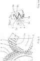
- Fig. 1 shows a first gear 1 and a second gear 2, which each have a helical gear 3, 4.
- the two gears 1, 2, also called spur gears 1, 2, are engaged with each other and generate due to the helical teeth Axial forces.
- Both spur gears 1, 2 each have an approximately equal tooth width b.
- the helical gearing 3, also referred to below as gearing 3 is elevated in the central region of the tooth width b, so that prismatic bodies 5 are formed, which are arranged like roof-shaped ridges or serrations on the tooth tips.
- the prismatic bodies 5, also generally called elevations 5, have contact surfaces 5a on both sides, which in Fig. 1 a are shown enlarged. In the drawing, only the front contact surfaces 5a are visible.
- Corresponding to the elevations 5 on the first spur gear 1 is in the second spur gear 2, a circumferential groove 6, also called annular groove 6, incorporated, in which engage the elevations 5.
- Fig. 1 a shows the engagement of the two spur gears 3, 4 of the first and the second spur gear 1, 2 in a view in the axial direction.
- a tooth of the helical gearing 3 has a tooth profile 3a with a tooth head 3b and a tip circle diameter D K1 .
- the toothing 4 of the second spur gear 2 has a tooth profile 4a with a root diameter D F2 .
- the incorporated into the second spur gear 2 annular groove 6 extends in the radial direction over the personally Vietnamese crochet messyr D F2 inward and has a groove base diameter D N shown in dashed lines, where D N ⁇ D F2 .
- the elevation is arranged in the form of the prismatic body 5, which in Fig.
- FIG. 1 and Fig. 1 A illustrated embodiment represents one of several solutions of the invention. Possible - but not shown - is z. As well as that several elevations or prismatic bodies are provided in the direction of the tooth width b, which engage in corresponding annular grooves on the second spur gear. Thus, a larger overlap area for transmitting the axial forces can be created. However, it is also possible to arrange the elevations frontally on the first spur gear 2, wherein the elevations each have only one inwardly directed contact surface and engage around the second spur gear from the outside. This creates a closed power flow within the spur gear stage with regard to the axial forces that occur.
Landscapes
- Engineering & Computer Science (AREA)
- General Engineering & Computer Science (AREA)
- Mechanical Engineering (AREA)
- Gears, Cams (AREA)
- Gear Transmission (AREA)
Description
- Die Erfindung betrifft ein Zahnradgetriebe, umfassend mindestens zwei miteinander kämmende Stirnräder mit Schrägverzahnung nach dem Oberbegriff des Patentanspruches 1.
- Bei Stirnradstufen mit Schrägverzahnung treten Axialkräfte auf, welche durch entsprechend dimensionierte Axiallager aufgenommen werden müssen. Hierfür werden häufig Kegelrollenlager verwendet, die einerseits relativ teuer sind und andererseits eine relativ hohe Wärmentwicklung aufweisen. Man hat daher bereits vorgeschlagen, anstelle der kostenaufwändigen Axiallager so genannte Druckkämme an den Stirnrädern mit Schrägverzahnung anzuordnen, wodurch die Axialkräfte aufgenommen werden. In dem Fachaufsatz "Hydrodynamische Axialkraftübertragung bei Wellen schnelllaufender Getriebe" von H. Langer, veröffentlicht in der Zeitschrift Konstruktion 34 (1982) Heft 12, Seite 473 - 478 sind derartige Druckkämme beschrieben. Der bekannte Druckkamm wird als separates, ringförmig ausgebildetes Einzelteil (Druckring) hergestellt und mit dem betreffenden Stirnrad gefügt, wobei die Befestigung zwischen Stirnrad und Druckring im Allgemeinen durch eine Schrumpfpassung erfolgt. Der Druckring, der mittig oder stirnseitig am Stirnrad befestigt wird, weist bevorzugt kegelförmig ausgebildete Anlaufflächen auf, welche sich an entsprechenden Anlaufflächen des Gegenrades, z. B. den Nutflanken einer Ringnut am Gegenrad abstützen. Zwischen den Anlaufflächen bildet sich ein Schmierfilm aus. Nachteilig bei den bekannten als zusätzliches Bauteil hergestellten Druckringen oder Druckkämmen ist die nicht immer zuverlässige Befestigung auf dem Stirnrad. Infolge Fliehkrafteinwirkung während des Betriebes kann es zu einem Lockern oder Lösen des Schrumpfsitzes kommen.
- Durch die
DE 1 215 463 wurde ein Zahnradgetriebe mit einem schräg verzahnten Ritzel bekannt, auf welches mittig ein Ring mit konischen Anlageflächen aufgeschrumpft ist. Die konischen Anlageflächen laufen gegen Nutflanken einer Ringnut, welche mittig in den beiden Gegenrädern, die mit dem Ritzel kämmen, angeordnet sind. Der Ring, der auch als Druckkamm bezeichnet werden kann, nimmt die aus der Schrägverzahnung resultierenden Axialkräfte auf, sodass entsprechende Axiallager entfallen können. - Es ist Aufgabe der vorliegenden Erfindung, ein Zahnradgetriebe der eingangs genannten Art derart auszubilden, dass die aus der Schrägverzahnung resultierenden Axialkräfte möglichst ohne Axiallager sicher und dauerhaft aufgenommen werden können.
- Die Aufgabe der Erfindung wird durch die Merkmale des unabhängigen Patentanspruches 1 gelöst. Vorteilhafte Ausgestaltungen ergeben sich aus den Unteransprüchen.
- Erfindungsgemäß ist bei dem ersten Stirnrad mindestens eine Überhöhung des Zahnprofils über den Kopfkreis hinaus vorgesehen, wobei sich die Überhöhung partiell über einen oder mehrere Bereiche der Zahnbreite erstreckt. Durch die Überhöhung des Zahnprofils, d. h. der Verzahnung ergibt sich ein zugespitztes Zahnprofil, welches im Bereich der Überhöhung mindestens eine seitliche Anlauffläche aufweist. Durch die Überhöhung des Zahnprofils können die aus der Schrägverzahnung resultierenden Axialkräfte innerhalb der Stirnradstufe aufgenommen werden, indem sich die mindestens eine Anlauffläche am ersten Stirnrad an einer korrespondierenden Anlauffläche am zweiten Stirnrad in axialer Richtung abstützt. Eine Paarung von Anlaufflächen am ersten und am zweiten Stirnrad führt zu einer Abstützung in einer axialen Richtung, während zwei Paarungen von Anlaufflächen am ersten und am zweiten Stirnrad zu einer Abstützung in beiden axialen Richtungen führen. Die Überhöhung des Zahnprofils führt zu einer Überdeckung beider Stirnräder in axialer Richtung. Dadurch können aufwändige Axiallager, z. B. Kegelrollenlager entfallen, was die Herstellungskosten eines solchen Zahnradgetriebes erheblich senkt. Im Gegensatz zum eingangs genannten Stand der Technik sind die Überhöhungen an jedem einzelnen Zahnprofil, d. h. am Zahnkopf einstückig mit der Verzahnung bzw. dem Stirnrad oder Zahnkranz ausgebildet. Es wird zunächst eine Verzahnung mit über die gesamte Zahnbreite durchgehender Überhöhung hergestellt, und anschließend wird das über den Kopfkreis hinausstehende Material spangebend teilweise abgetragen, z. B. abgedreht, sodass partielle Überhöhungen stehen bleiben. Vorteilhaft bei dieser einstückigen Ausbildung ist, dass kein zusätzliches Bauteil zur Aufnahme der Axialkräfte in Form eines zusätzlichen ringförmigen Druckkammes benötigt wird, der sich unter der betrieblichen Beanspruchung lockern oder lösen könnte. Insofern ist die erfindungsgemäße Lösung sicherer und dauerhafter.
- Nach einer bevorzugten Ausführungsform ist die mindestens eine Überhöhung innerhalb der Zahnbreite angeordnet: Beispielsweise kann eine Überhöhung in der Mitte der Zahnbreite angeordnet oder es können mehrere Überhöhungen über den Bereich der Zahnbreite vorgesehen sein. Jeder Überhöhung ist eine Ringnut am zweiten Stirnrad zugeordnet, in welche die Überhöhung am Zahnprofil eingreift und damit eine Überdeckung in axialer Richtung herstellt. Die Ringnut bildet mit ihren Nutflanken die Anlaufflächen für die an den Überhöhungen angeordneten Anlaufflächen.
- Nach einer weiteren bevorzugten Ausführungsform sind nur an den Stirnseiten des ersten Stirnrades Überhöhungen vorgesehen, welche das zweite Stirnrad umfassen. Am zweiten Stirnrad ist dann keine Ringnut erforderlich, sondern lediglich stirnseitig angeordnete Anlaufflächen, welche mit den Anlaufflächen an den Überhöhungen zwei Paarungen bilden, welche die Axialkräfte in beiden Richtungen aufnehmen. Die Anlaufflächen können plan, konisch oder ballig ausgebildet sein. Wie aus dem eingangs genannten Stand der Technik bekannt, bildet sich zwischen den Anlaufflächen vom ersten und zweiten Stirnrad ein Schmierfilm aus.
- Ein Ausführungsbeispiel der Erfindung ist in der Zeichnung dargestellt und wird im Folgenden näher beschrieben. Es zeigen
- Fig. 1
- einen Ausschnitt einer erfindungsgemäßen Stirnradstufe in perspektivischer Darstellung und
- Fig. 1a
- einen vergrößerten Ausschnitt des Zahneingriffes beider Stirnräder.
-
Fig. 1 zeigt ein erstes Zahnrad 1 und ein zweites Zahnrad 2, welche jeweils eine Schrägverzahnung 3, 4 aufweisen. Die beiden Zahnräder 1, 2, auch Stirnräder 1, 2 genannt, stehen miteinander in Eingriff und erzeugen aufgrund der Schrägverzahnung Axialkräfte. Beide Stirnräder 1, 2 weisen jeweils eine etwa gleichgroße Zahnbreite b auf. Am ersten Stirnrad 1 ist die Schrägverzahnung 3, im Folgenden auch kurz Verzahnung 3 genannt, im mittleren Bereich der Zahnbreite b überhöht, sodass prismatische Körper 5 ausgebildet werden, welche wie dachförmige Reiter oder Zacken auf den Zahnköpfen angeordnet sind. Die prismatischen Körper 5, allgemein auch Überhöhungen 5 genannt, weisen beiderseits Anlaufflächen 5a auf, welche inFig. 1 a vergrößert dargestellt sind. In der Zeichnung sind jeweils nur die vorderen Anlaufflächen 5a erkennbar. Korrespondierend zu den Überhöhungen 5 am ersten Stirnrad 1 ist im zweiten Stirnrad 2 eine umlaufende Nut 6, auch Ringnut 6 genannt, eingearbeitet, in welche die Überhöhungen 5 eingreifen. -
Fig. 1 a zeigt den Eingriff der beiden Stirnverzahnungen 3, 4 des ersten und des zweiten Stirnrades 1, 2 in einer Ansicht in axialer Richtung. Ein Zahn der Schrägverzahnung 3 weist ein Zahnprofil 3a mit einem Zahnkopf 3b und einem Kopfkreisdurchmesser DK1 auf. Die Verzahnung 4 des zweiten Stirnrades 2 weist ein Zahnprofil 4a mit einem Fußkreisdurchmesser DF2 auf. Die in das zweite Stirnrad 2 eingearbeitete Ringnut 6 erstreckt sich in radialer Richtung über den Fußkreisdurchmesser DF2 nach innen und weist einen gestrichelt dargestellten Nutgrunddurchmesser DN auf, wobei DN < DF2 ist. Auf dem Zahnkopf 3b des ersten Stirnrades 1 ist die Überhöhung in Form des prismatischen Körpers 5 angeordnet, welcher inFig. 1 a etwa die Form eines gleichseitigen Dreiecks aufweist. Im Bereich der Ringnut 6 ergibt sich durch den über den Fußkreisdurchmesser DF2 hineinragenden prismatischen Körper 5 eine Überdeckung 5a' in axialer Richtung, über welche die Axialkräfte übertragen werden. Die auf den Zahnköpfen 3b angeordneten prismatischen Körper 5 sind einstückig mit der Stirnverzahnung 3 hergestellt, wobei letztere einstückig mit dem ersten Stirnrad 1 oder als Zahnkranz ausgebildet sein kann. Man stellt also vorzugsweise zunächst eine Stirnverzahnung mit einem vorläufigen Kopfkreisdurchmesser her, der größer als der Kopfkreisdurchmesser DK2 der fertigen Schrägverzahnung 3 ist. Anschließend wird das Material beiderseits der Zacken 5 spangebend abgetragen, z. B. durch Abdrehen. Die Überhöhungen 5 bleiben dann - wie inFig. 1 dargestellt - stehen. - Die in
Fig. 1 und Fig. 1 a dargestellte Ausführungsform stellt eine von mehreren erfindungsgemäßen Lösungen dar. Möglich - jedoch nicht dargestellt - ist z. B. auch, dass mehrere Überhöhungen oder prismatische Körper in Richtung der Zahnbreite b vorgesehen werden, welche in entsprechende Ringnuten am zweiten Stirnrad eingreifen. Damit kann eine größere Überdeckungsfläche zur Übertragung der Axialkräfte geschaffen werden. Möglich ist es jedoch auch, die Überhöhungen stirnseitig am ersten Stirnrad 2 anzuordnen, wobei die Überhöhungen jeweils nur eine nach innen gerichtete Anlagefläche aufweisen und das zweite Stirnrad von außen umgreifen. Damit ist ein hinsichtlich der auftretenden Axialkräfte geschlossener Kraftfluss innerhalb der Stirnradstufe geschaffen. -
- 1
- erstes Stirnrad
- 2
- zweites Stirnrad
- 3
- Schrägverzahnung
- 3a
- Zahnprofil
- 3b
- Zahnkopf
- 4
- Schrägverzahnung
- 4a
- Zahnprofil
- 5
- Überhöhung (prismatischer Körper)
- 5a
- Anlauffläche
- 5a'
- Überdeckung
- 6
- Ringnut
- b
- Zahnbreite
- DK1
- Kopfkreisdurchmesser, Rad 1
- DF2
- Fußkreisdurchmesser, Rad 2
- DN
- Nutgrunddurchmesser, Rad 2
Claims (7)
- Zahnradgetriebe, umfassend mindestens zwei miteinander kämmende, eine Zahnbreite (b) aufweisende Stirnräder (1, 2) mit Schrägverzahnungen (3, 4), wobei ein erstes Stirnrad (1) ein Zahnprofil (3a) mit einem Kopfkreisdurchmesser (DK1) und ein zweites Stirnrad (2) ein Zahnprofil (4a) mit einem Fußkreisdurchmesser (DF2) aufweisen, dadurch gekennzeichnet, dass das erste Stirnrad (1) mindestens eine sich partiell über die Zahnbreite erstreckende Überhöhung (5) des Zahnprofils (3a) über den Kopfkreisdurchmesser (DK1) hinaus aufweist und dass die mindestens eine Überhöhung (5) mindestens eine Anlauffläche (5a) in axialer Richtung aufweist.
- Zahnradgetriebe nach Anspruch 1, dadurch gekennzeichnet, dass die mindestens eine Überhöhung (5) innerhalb der Zahnbreite (b) angeordnet und dass der mindestens einen Überhöhung (5) am zweiten Stirnrad (2) eine Ringnut (6) zugeordnet ist, deren Nutflanken Anlaufflächen bilden.
- Zahnradgetriebe nach Anspruch 2, dadurch gekennzeichnet, dass die Ringnut (6) einen Nutgrunddurchmesser (DN) aufweist, der kleiner als der Fußkreisdurchmesser (DF2) ist.
- Zahnradgetriebe nach Anspruch 2 oder 3, dadurch gekennzeichnet, dass die Überhöhung (5) und die korrespondierende Ringnut (6) etwa in der Mitte der Zahnbreite (b) angeordnet sind und Anlaufflächen (5a) auf beiden Seiten aufweisen.
- Zahnradgetriebe nach Anspruch 1, dadurch gekennzeichnet, dass die mindestens eine Überhöhung (5) am ersten Stirnrad (1) stirnseitig angeordnet ist und das zweite Stirnrad (2) umfassen.
- Zahnradgetriebe nach einem der Ansprüche 1 bis 5, dadurch gekennzeichnet, dass die mindestens eine Überhöhung (5) als prismatischer Körper (5) ausgebildet ist.
- Zahnradgetriebe nach einem der Ansprüche 1 bis 6, dadurch gekennzeichnet, dass die mindestens eine Überhöhung (5) einstückig mit der Schrägverzahnung (3) ausgebildet ist.
Applications Claiming Priority (2)
| Application Number | Priority Date | Filing Date | Title |
|---|---|---|---|
| DE201010062364 DE102010062364A1 (de) | 2010-12-02 | 2010-12-02 | Zahnradgetriebe mit Schrägverzahnung |
| PCT/EP2011/069512 WO2012072373A1 (de) | 2010-12-02 | 2011-11-07 | Zahnradgetriebe mit schrägverzahnung |
Publications (2)
| Publication Number | Publication Date |
|---|---|
| EP2646712A1 EP2646712A1 (de) | 2013-10-09 |
| EP2646712B1 true EP2646712B1 (de) | 2016-03-23 |
Family
ID=44906180
Family Applications (1)
| Application Number | Title | Priority Date | Filing Date |
|---|---|---|---|
| EP11778914.9A Not-in-force EP2646712B1 (de) | 2010-12-02 | 2011-11-07 | Zahnradgetriebe mit schrägverzahnung |
Country Status (7)
| Country | Link |
|---|---|
| US (1) | US9016157B2 (de) |
| EP (1) | EP2646712B1 (de) |
| CN (1) | CN103228958B (de) |
| DE (1) | DE102010062364A1 (de) |
| ES (1) | ES2574184T3 (de) |
| RU (1) | RU2551251C2 (de) |
| WO (1) | WO2012072373A1 (de) |
Families Citing this family (5)
| Publication number | Priority date | Publication date | Assignee | Title |
|---|---|---|---|---|
| DE102010062364A1 (de) * | 2010-12-02 | 2012-06-06 | Zf Friedrichshafen Ag | Zahnradgetriebe mit Schrägverzahnung |
| CN103742626B (zh) * | 2014-01-21 | 2017-01-25 | 谭奇万 | 一种齿轮的轮齿结构及其齿轮泵及其流体传动装置 |
| CN105545927A (zh) * | 2015-11-27 | 2016-05-04 | 沪东重机有限公司 | 便于失效更替的柴油机曲轴齿轮连接结构 |
| CN105889416A (zh) * | 2016-06-23 | 2016-08-24 | 长沙艾科瑞齿轮机械有限责任公司 | 一种平衡轴向力的斜齿传动装置及使用该装置的行星齿轮 |
| CN109114169A (zh) * | 2018-10-08 | 2019-01-01 | 天津工业大学 | 航空螺旋面齿轮传动系统 |
Family Cites Families (21)
| Publication number | Priority date | Publication date | Assignee | Title |
|---|---|---|---|---|
| FR632830A (de) * | 1922-06-15 | 1928-01-16 | ||
| US1766153A (en) * | 1928-11-19 | 1930-06-24 | Trbojevich Nikola | Sliding-gear and method of synchronizing the same |
| US2335504A (en) * | 1942-11-13 | 1943-11-30 | Gazda Antoine | Gear tooth |
| GB918241A (en) * | 1959-07-06 | 1963-02-13 | Smidth & Co As F L | Improvements in gear trains |
| DE1188890B (de) * | 1962-08-09 | 1965-03-11 | Gustav Niemann Dr Ing | Stirnradgetriebe |
| DE1215463B (de) | 1962-12-22 | 1966-04-28 | Asea Ab | Zahnradgetriebe |
| NL7004747A (de) * | 1970-04-02 | 1971-10-05 | ||
| JPS5397151A (en) * | 1977-02-02 | 1978-08-25 | Kanji Imazaike | Gear |
| DE3022020C2 (de) | 1980-06-12 | 1982-09-30 | Voith Getriebe Kg, 7920 Heidenheim | Axiale Kraftübertragungs-Einrichtung für ein Stirnradgetriebe |
| JPS57131652U (de) * | 1981-02-10 | 1982-08-17 | ||
| FR2519722B1 (fr) * | 1982-01-08 | 1985-07-26 | Intelautomatisme Cie | Butee a collet a double effet pour train d'engrenages a axes paralleles |
| DE3934377A1 (de) * | 1988-11-09 | 1990-05-10 | Borg Warner Automotive | Anti-klappervorrichtung fuer ein getriebe |
| GB2304169B (en) * | 1995-08-10 | 1997-07-09 | Samsung Electronics Co Ltd | Gear mechanisms |
| US6230578B1 (en) * | 1999-04-30 | 2001-05-15 | Axicon Technologies, Inc. | Variable face width gearing |
| RU2191937C2 (ru) * | 2000-06-07 | 2002-10-27 | ОАО "Ижевский завод нефтяного машиностроения" | Косозубая цилиндрическая передача с упорными кольцами |
| US6837123B2 (en) * | 2001-03-23 | 2005-01-04 | Hawkins Richard M | Non-involute gears with conformal contact |
| US6993989B2 (en) * | 2002-04-26 | 2006-02-07 | Denso Corporation | Starting apparatus |
| JP4470163B2 (ja) * | 2003-09-03 | 2010-06-02 | 株式会社エンプラス | 成形プラスチック歯車及びこれを使用した間歇回転伝達機構、成形プラスチック歯車の使用方法 |
| US7926380B2 (en) * | 2006-05-17 | 2011-04-19 | Murata Machinery, Ltd. | Resin gears, developing unit, photoconductor drum unit, image forming apparatus or image reading apparatus having the same |
| AT508260B1 (de) * | 2009-05-20 | 2010-12-15 | Miba Sinter Austria Gmbh | Zahnrad |
| DE102010062364A1 (de) * | 2010-12-02 | 2012-06-06 | Zf Friedrichshafen Ag | Zahnradgetriebe mit Schrägverzahnung |
-
2010
- 2010-12-02 DE DE201010062364 patent/DE102010062364A1/de not_active Withdrawn
-
2011
- 2011-11-07 RU RU2013129954/11A patent/RU2551251C2/ru active
- 2011-11-07 US US13/883,063 patent/US9016157B2/en not_active Expired - Fee Related
- 2011-11-07 CN CN201180056063.3A patent/CN103228958B/zh not_active Expired - Fee Related
- 2011-11-07 ES ES11778914.9T patent/ES2574184T3/es active Active
- 2011-11-07 EP EP11778914.9A patent/EP2646712B1/de not_active Not-in-force
- 2011-11-07 WO PCT/EP2011/069512 patent/WO2012072373A1/de not_active Ceased
Also Published As
| Publication number | Publication date |
|---|---|
| US20130239724A1 (en) | 2013-09-19 |
| ES2574184T3 (es) | 2016-06-15 |
| CN103228958A (zh) | 2013-07-31 |
| CN103228958B (zh) | 2017-02-15 |
| RU2013129954A (ru) | 2015-01-10 |
| WO2012072373A1 (de) | 2012-06-07 |
| DE102010062364A1 (de) | 2012-06-06 |
| RU2551251C2 (ru) | 2015-05-20 |
| EP2646712A1 (de) | 2013-10-09 |
| US9016157B2 (en) | 2015-04-28 |
Similar Documents
| Publication | Publication Date | Title |
|---|---|---|
| EP1834102B1 (de) | Wellen-naben-verbindung mit sicherungssystem | |
| DE102012214884B3 (de) | Kupplungsanordnung und Kupplungselement | |
| EP2184514B1 (de) | Spannungswellengetriebe | |
| DE102004062379B3 (de) | Zahnradpaarung aus Kronenrad und Ritzel | |
| DE102004006723A1 (de) | Planetenradgetriebe | |
| DE2843459A1 (de) | Stirnrad-planetengetriebe mit lastausgleich | |
| EP2730807B1 (de) | Planetengetriebe mit mehreren Getriebestufen | |
| EP2182233B1 (de) | Synchronnabe | |
| DE2924349A1 (de) | Druckkammgetriebe | |
| DE102019125310A1 (de) | Planetenwälzgetriebe | |
| AT518787B1 (de) | Zahnradanordnung | |
| DE10329870B3 (de) | Zahnrad und Zahnradsatz | |
| WO2012072373A1 (de) | Zahnradgetriebe mit schrägverzahnung | |
| DE3121662A1 (de) | "getriebe" | |
| AT520015B1 (de) | Baugruppe mit einer Steckverzahnung | |
| WO2015154920A1 (de) | Elektromechanische lenkvorrichtung mit einem zahnrad und verfahren zum herstellen eines zahnrads | |
| EP4155580B1 (de) | Koaxialgetriebe | |
| DE2458399A1 (de) | Universalfraeskopf | |
| DE102017111039A1 (de) | Mehrteiliges Zahnrad mit Welle-Nabe-Verbindung | |
| DE3022020C2 (de) | Axiale Kraftübertragungs-Einrichtung für ein Stirnradgetriebe | |
| DE2545681A1 (de) | Getriebe | |
| EP3169913B1 (de) | Wellgetriebe mit trockenlauf | |
| DE10235677B4 (de) | Einseitige axiale Sicherung von Zahnrädern in Kronenradwinkeltrieben | |
| DE19929639B4 (de) | Welle-Nabe-Verbindung mit umgeformten Anschlagschrägen in Wellenverzahnung | |
| DE102019212221A1 (de) | Wellgetriebe |
Legal Events
| Date | Code | Title | Description |
|---|---|---|---|
| PUAI | Public reference made under article 153(3) epc to a published international application that has entered the european phase |
Free format text: ORIGINAL CODE: 0009012 |
|
| 17P | Request for examination filed |
Effective date: 20130516 |
|
| AK | Designated contracting states |
Kind code of ref document: A1 Designated state(s): AL AT BE BG CH CY CZ DE DK EE ES FI FR GB GR HR HU IE IS IT LI LT LU LV MC MK MT NL NO PL PT RO RS SE SI SK SM TR |
|
| DAX | Request for extension of the european patent (deleted) | ||
| GRAP | Despatch of communication of intention to grant a patent |
Free format text: ORIGINAL CODE: EPIDOSNIGR1 |
|
| RIC1 | Information provided on ipc code assigned before grant |
Ipc: F16H 1/08 20060101ALI20150921BHEP Ipc: F16H 57/02 20120101AFI20150921BHEP |
|
| INTG | Intention to grant announced |
Effective date: 20151021 |
|
| GRAS | Grant fee paid |
Free format text: ORIGINAL CODE: EPIDOSNIGR3 |
|
| GRAA | (expected) grant |
Free format text: ORIGINAL CODE: 0009210 |
|
| AK | Designated contracting states |
Kind code of ref document: B1 Designated state(s): AL AT BE BG CH CY CZ DE DK EE ES FI FR GB GR HR HU IE IS IT LI LT LU LV MC MK MT NL NO PL PT RO RS SE SI SK SM TR |
|
| REG | Reference to a national code |
Ref country code: GB Ref legal event code: FG4D Free format text: NOT ENGLISH |
|
| REG | Reference to a national code |
Ref country code: CH Ref legal event code: EP |
|
| REG | Reference to a national code |
Ref country code: AT Ref legal event code: REF Ref document number: 783478 Country of ref document: AT Kind code of ref document: T Effective date: 20160415 |
|
| REG | Reference to a national code |
Ref country code: IE Ref legal event code: FG4D Free format text: LANGUAGE OF EP DOCUMENT: GERMAN |
|
| REG | Reference to a national code |
Ref country code: DE Ref legal event code: R096 Ref document number: 502011009195 Country of ref document: DE |
|
| REG | Reference to a national code |
Ref country code: RO Ref legal event code: EPE |
|
| REG | Reference to a national code |
Ref country code: ES Ref legal event code: FG2A Ref document number: 2574184 Country of ref document: ES Kind code of ref document: T3 Effective date: 20160615 |
|
| REG | Reference to a national code |
Ref country code: SE Ref legal event code: TRGR |
|
| REG | Reference to a national code |
Ref country code: LT Ref legal event code: MG4D |
|
| REG | Reference to a national code |
Ref country code: NL Ref legal event code: MP Effective date: 20160323 |
|
| PG25 | Lapsed in a contracting state [announced via postgrant information from national office to epo] |
Ref country code: FI Free format text: LAPSE BECAUSE OF FAILURE TO SUBMIT A TRANSLATION OF THE DESCRIPTION OR TO PAY THE FEE WITHIN THE PRESCRIBED TIME-LIMIT Effective date: 20160323 Ref country code: GR Free format text: LAPSE BECAUSE OF FAILURE TO SUBMIT A TRANSLATION OF THE DESCRIPTION OR TO PAY THE FEE WITHIN THE PRESCRIBED TIME-LIMIT Effective date: 20160624 Ref country code: HR Free format text: LAPSE BECAUSE OF FAILURE TO SUBMIT A TRANSLATION OF THE DESCRIPTION OR TO PAY THE FEE WITHIN THE PRESCRIBED TIME-LIMIT Effective date: 20160323 Ref country code: NO Free format text: LAPSE BECAUSE OF FAILURE TO SUBMIT A TRANSLATION OF THE DESCRIPTION OR TO PAY THE FEE WITHIN THE PRESCRIBED TIME-LIMIT Effective date: 20160623 |
|
| PG25 | Lapsed in a contracting state [announced via postgrant information from national office to epo] |
Ref country code: NL Free format text: LAPSE BECAUSE OF FAILURE TO SUBMIT A TRANSLATION OF THE DESCRIPTION OR TO PAY THE FEE WITHIN THE PRESCRIBED TIME-LIMIT Effective date: 20160323 Ref country code: LV Free format text: LAPSE BECAUSE OF FAILURE TO SUBMIT A TRANSLATION OF THE DESCRIPTION OR TO PAY THE FEE WITHIN THE PRESCRIBED TIME-LIMIT Effective date: 20160323 Ref country code: LT Free format text: LAPSE BECAUSE OF FAILURE TO SUBMIT A TRANSLATION OF THE DESCRIPTION OR TO PAY THE FEE WITHIN THE PRESCRIBED TIME-LIMIT Effective date: 20160323 Ref country code: RS Free format text: LAPSE BECAUSE OF FAILURE TO SUBMIT A TRANSLATION OF THE DESCRIPTION OR TO PAY THE FEE WITHIN THE PRESCRIBED TIME-LIMIT Effective date: 20160323 |
|
| REG | Reference to a national code |
Ref country code: FR Ref legal event code: PLFP Year of fee payment: 6 |
|
| PG25 | Lapsed in a contracting state [announced via postgrant information from national office to epo] |
Ref country code: IS Free format text: LAPSE BECAUSE OF FAILURE TO SUBMIT A TRANSLATION OF THE DESCRIPTION OR TO PAY THE FEE WITHIN THE PRESCRIBED TIME-LIMIT Effective date: 20160723 Ref country code: EE Free format text: LAPSE BECAUSE OF FAILURE TO SUBMIT A TRANSLATION OF THE DESCRIPTION OR TO PAY THE FEE WITHIN THE PRESCRIBED TIME-LIMIT Effective date: 20160323 Ref country code: PL Free format text: LAPSE BECAUSE OF FAILURE TO SUBMIT A TRANSLATION OF THE DESCRIPTION OR TO PAY THE FEE WITHIN THE PRESCRIBED TIME-LIMIT Effective date: 20160323 |
|
| PG25 | Lapsed in a contracting state [announced via postgrant information from national office to epo] |
Ref country code: SK Free format text: LAPSE BECAUSE OF FAILURE TO SUBMIT A TRANSLATION OF THE DESCRIPTION OR TO PAY THE FEE WITHIN THE PRESCRIBED TIME-LIMIT Effective date: 20160323 Ref country code: SM Free format text: LAPSE BECAUSE OF FAILURE TO SUBMIT A TRANSLATION OF THE DESCRIPTION OR TO PAY THE FEE WITHIN THE PRESCRIBED TIME-LIMIT Effective date: 20160323 Ref country code: PT Free format text: LAPSE BECAUSE OF FAILURE TO SUBMIT A TRANSLATION OF THE DESCRIPTION OR TO PAY THE FEE WITHIN THE PRESCRIBED TIME-LIMIT Effective date: 20160725 |
|
| REG | Reference to a national code |
Ref country code: DE Ref legal event code: R097 Ref document number: 502011009195 Country of ref document: DE |
|
| PLBE | No opposition filed within time limit |
Free format text: ORIGINAL CODE: 0009261 |
|
| STAA | Information on the status of an ep patent application or granted ep patent |
Free format text: STATUS: NO OPPOSITION FILED WITHIN TIME LIMIT |
|
| PG25 | Lapsed in a contracting state [announced via postgrant information from national office to epo] |
Ref country code: DK Free format text: LAPSE BECAUSE OF FAILURE TO SUBMIT A TRANSLATION OF THE DESCRIPTION OR TO PAY THE FEE WITHIN THE PRESCRIBED TIME-LIMIT Effective date: 20160323 |
|
| PG25 | Lapsed in a contracting state [announced via postgrant information from national office to epo] |
Ref country code: BG Free format text: LAPSE BECAUSE OF FAILURE TO SUBMIT A TRANSLATION OF THE DESCRIPTION OR TO PAY THE FEE WITHIN THE PRESCRIBED TIME-LIMIT Effective date: 20160623 Ref country code: BE Free format text: LAPSE BECAUSE OF NON-PAYMENT OF DUE FEES Effective date: 20161130 |
|
| 26N | No opposition filed |
Effective date: 20170102 |
|
| PG25 | Lapsed in a contracting state [announced via postgrant information from national office to epo] |
Ref country code: SI Free format text: LAPSE BECAUSE OF FAILURE TO SUBMIT A TRANSLATION OF THE DESCRIPTION OR TO PAY THE FEE WITHIN THE PRESCRIBED TIME-LIMIT Effective date: 20160323 |
|
| REG | Reference to a national code |
Ref country code: CH Ref legal event code: PL |
|
| GBPC | Gb: european patent ceased through non-payment of renewal fee |
Effective date: 20161107 |
|
| PG25 | Lapsed in a contracting state [announced via postgrant information from national office to epo] |
Ref country code: CH Free format text: LAPSE BECAUSE OF NON-PAYMENT OF DUE FEES Effective date: 20161130 Ref country code: LI Free format text: LAPSE BECAUSE OF NON-PAYMENT OF DUE FEES Effective date: 20161130 |
|
| REG | Reference to a national code |
Ref country code: IE Ref legal event code: MM4A |
|
| PG25 | Lapsed in a contracting state [announced via postgrant information from national office to epo] |
Ref country code: LU Free format text: LAPSE BECAUSE OF NON-PAYMENT OF DUE FEES Effective date: 20161130 |
|
| REG | Reference to a national code |
Ref country code: FR Ref legal event code: PLFP Year of fee payment: 7 |
|
| PG25 | Lapsed in a contracting state [announced via postgrant information from national office to epo] |
Ref country code: IE Free format text: LAPSE BECAUSE OF NON-PAYMENT OF DUE FEES Effective date: 20161107 Ref country code: GB Free format text: LAPSE BECAUSE OF NON-PAYMENT OF DUE FEES Effective date: 20161107 |
|
| REG | Reference to a national code |
Ref country code: AT Ref legal event code: MM01 Ref document number: 783478 Country of ref document: AT Kind code of ref document: T Effective date: 20161107 |
|
| PG25 | Lapsed in a contracting state [announced via postgrant information from national office to epo] |
Ref country code: AT Free format text: LAPSE BECAUSE OF NON-PAYMENT OF DUE FEES Effective date: 20161107 |
|
| REG | Reference to a national code |
Ref country code: BE Ref legal event code: MM Effective date: 20161130 |
|
| PGFP | Annual fee paid to national office [announced via postgrant information from national office to epo] |
Ref country code: IT Payment date: 20171123 Year of fee payment: 7 Ref country code: SE Payment date: 20171113 Year of fee payment: 7 |
|
| PG25 | Lapsed in a contracting state [announced via postgrant information from national office to epo] |
Ref country code: CY Free format text: LAPSE BECAUSE OF FAILURE TO SUBMIT A TRANSLATION OF THE DESCRIPTION OR TO PAY THE FEE WITHIN THE PRESCRIBED TIME-LIMIT Effective date: 20160323 Ref country code: HU Free format text: LAPSE BECAUSE OF FAILURE TO SUBMIT A TRANSLATION OF THE DESCRIPTION OR TO PAY THE FEE WITHIN THE PRESCRIBED TIME-LIMIT; INVALID AB INITIO Effective date: 20111107 |
|
| PG25 | Lapsed in a contracting state [announced via postgrant information from national office to epo] |
Ref country code: MC Free format text: LAPSE BECAUSE OF FAILURE TO SUBMIT A TRANSLATION OF THE DESCRIPTION OR TO PAY THE FEE WITHIN THE PRESCRIBED TIME-LIMIT Effective date: 20160323 Ref country code: MK Free format text: LAPSE BECAUSE OF FAILURE TO SUBMIT A TRANSLATION OF THE DESCRIPTION OR TO PAY THE FEE WITHIN THE PRESCRIBED TIME-LIMIT Effective date: 20160323 |
|
| PG25 | Lapsed in a contracting state [announced via postgrant information from national office to epo] |
Ref country code: MT Free format text: LAPSE BECAUSE OF FAILURE TO SUBMIT A TRANSLATION OF THE DESCRIPTION OR TO PAY THE FEE WITHIN THE PRESCRIBED TIME-LIMIT Effective date: 20160323 |
|
| REG | Reference to a national code |
Ref country code: FR Ref legal event code: PLFP Year of fee payment: 8 |
|
| PG25 | Lapsed in a contracting state [announced via postgrant information from national office to epo] |
Ref country code: AL Free format text: LAPSE BECAUSE OF FAILURE TO SUBMIT A TRANSLATION OF THE DESCRIPTION OR TO PAY THE FEE WITHIN THE PRESCRIBED TIME-LIMIT Effective date: 20160323 Ref country code: TR Free format text: LAPSE BECAUSE OF FAILURE TO SUBMIT A TRANSLATION OF THE DESCRIPTION OR TO PAY THE FEE WITHIN THE PRESCRIBED TIME-LIMIT Effective date: 20160323 |
|
| PGFP | Annual fee paid to national office [announced via postgrant information from national office to epo] |
Ref country code: ES Payment date: 20181203 Year of fee payment: 8 Ref country code: FR Payment date: 20181011 Year of fee payment: 8 |
|
| REG | Reference to a national code |
Ref country code: SE Ref legal event code: EUG |
|
| PG25 | Lapsed in a contracting state [announced via postgrant information from national office to epo] |
Ref country code: SE Free format text: LAPSE BECAUSE OF NON-PAYMENT OF DUE FEES Effective date: 20181108 |
|
| PG25 | Lapsed in a contracting state [announced via postgrant information from national office to epo] |
Ref country code: IT Free format text: LAPSE BECAUSE OF NON-PAYMENT OF DUE FEES Effective date: 20181107 |
|
| PGFP | Annual fee paid to national office [announced via postgrant information from national office to epo] |
Ref country code: RO Payment date: 20191002 Year of fee payment: 9 Ref country code: DE Payment date: 20191022 Year of fee payment: 9 |
|
| PG25 | Lapsed in a contracting state [announced via postgrant information from national office to epo] |
Ref country code: FR Free format text: LAPSE BECAUSE OF NON-PAYMENT OF DUE FEES Effective date: 20191130 |
|
| REG | Reference to a national code |
Ref country code: DE Ref legal event code: R119 Ref document number: 502011009195 Country of ref document: DE |
|
| PG25 | Lapsed in a contracting state [announced via postgrant information from national office to epo] |
Ref country code: RO Free format text: LAPSE BECAUSE OF NON-PAYMENT OF DUE FEES Effective date: 20201107 |
|
| PG25 | Lapsed in a contracting state [announced via postgrant information from national office to epo] |
Ref country code: ES Free format text: LAPSE BECAUSE OF NON-PAYMENT OF DUE FEES Effective date: 20191108 |
|
| PG25 | Lapsed in a contracting state [announced via postgrant information from national office to epo] |
Ref country code: DE Free format text: LAPSE BECAUSE OF NON-PAYMENT OF DUE FEES Effective date: 20210601 |
|
| P01 | Opt-out of the competence of the unified patent court (upc) registered |
Effective date: 20230528 |
|
| PGFP | Annual fee paid to national office [announced via postgrant information from national office to epo] |
Ref country code: CZ Payment date: 20231018 Year of fee payment: 13 |
|
| PG25 | Lapsed in a contracting state [announced via postgrant information from national office to epo] |
Ref country code: CZ Free format text: LAPSE BECAUSE OF NON-PAYMENT OF DUE FEES Effective date: 20241107 |