EP2646699B1 - Bearing wear detection assembly - Google Patents
Bearing wear detection assembly Download PDFInfo
- Publication number
- EP2646699B1 EP2646699B1 EP11797069.9A EP11797069A EP2646699B1 EP 2646699 B1 EP2646699 B1 EP 2646699B1 EP 11797069 A EP11797069 A EP 11797069A EP 2646699 B1 EP2646699 B1 EP 2646699B1
- Authority
- EP
- European Patent Office
- Prior art keywords
- bearing
- detection assembly
- wear detection
- recited
- bearing wear
- Prior art date
- Legal status (The legal status is an assumption and is not a legal conclusion. Google has not performed a legal analysis and makes no representation as to the accuracy of the status listed.)
- Active
Links
- 238000001514 detection method Methods 0.000 title claims description 24
- 239000000919 ceramic Substances 0.000 claims description 15
- BQCADISMDOOEFD-UHFFFAOYSA-N Silver Chemical compound [Ag] BQCADISMDOOEFD-UHFFFAOYSA-N 0.000 claims description 5
- 229910052709 silver Inorganic materials 0.000 claims description 5
- 239000004332 silver Substances 0.000 claims description 5
- 239000004020 conductor Substances 0.000 claims description 3
- 238000005516 engineering process Methods 0.000 description 16
- 239000004519 grease Substances 0.000 description 5
- 230000008901 benefit Effects 0.000 description 3
- 238000012423 maintenance Methods 0.000 description 3
- 229910000831 Steel Inorganic materials 0.000 description 2
- 239000000463 material Substances 0.000 description 2
- 238000000034 method Methods 0.000 description 2
- 239000010959 steel Substances 0.000 description 2
- 230000000712 assembly Effects 0.000 description 1
- 238000000429 assembly Methods 0.000 description 1
- 230000001934 delay Effects 0.000 description 1
- 238000013467 fragmentation Methods 0.000 description 1
- 238000006062 fragmentation reaction Methods 0.000 description 1
- 230000000977 initiatory effect Effects 0.000 description 1
- 239000000314 lubricant Substances 0.000 description 1
- 230000007257 malfunction Effects 0.000 description 1
- 230000007246 mechanism Effects 0.000 description 1
- 238000012986 modification Methods 0.000 description 1
- 230000004048 modification Effects 0.000 description 1
- 230000008439 repair process Effects 0.000 description 1
Images


Classifications
-
- F—MECHANICAL ENGINEERING; LIGHTING; HEATING; WEAPONS; BLASTING
- F16—ENGINEERING ELEMENTS AND UNITS; GENERAL MEASURES FOR PRODUCING AND MAINTAINING EFFECTIVE FUNCTIONING OF MACHINES OR INSTALLATIONS; THERMAL INSULATION IN GENERAL
- F16C—SHAFTS; FLEXIBLE SHAFTS; ELEMENTS OR CRANKSHAFT MECHANISMS; ROTARY BODIES OTHER THAN GEARING ELEMENTS; BEARINGS
- F16C19/00—Bearings with rolling contact, for exclusively rotary movement
- F16C19/52—Bearings with rolling contact, for exclusively rotary movement with devices affected by abnormal or undesired conditions
-
- F—MECHANICAL ENGINEERING; LIGHTING; HEATING; WEAPONS; BLASTING
- F16—ENGINEERING ELEMENTS AND UNITS; GENERAL MEASURES FOR PRODUCING AND MAINTAINING EFFECTIVE FUNCTIONING OF MACHINES OR INSTALLATIONS; THERMAL INSULATION IN GENERAL
- F16C—SHAFTS; FLEXIBLE SHAFTS; ELEMENTS OR CRANKSHAFT MECHANISMS; ROTARY BODIES OTHER THAN GEARING ELEMENTS; BEARINGS
- F16C33/00—Parts of bearings; Special methods for making bearings or parts thereof
- F16C33/72—Sealings
- F16C33/76—Sealings of ball or roller bearings
- F16C33/78—Sealings of ball or roller bearings with a diaphragm, disc, or ring, with or without resilient members
- F16C33/784—Sealings of ball or roller bearings with a diaphragm, disc, or ring, with or without resilient members mounted to a groove in the inner surface of the outer race and extending toward the inner race
- F16C33/7843—Sealings of ball or roller bearings with a diaphragm, disc, or ring, with or without resilient members mounted to a groove in the inner surface of the outer race and extending toward the inner race with a single annular sealing disc
- F16C33/7846—Sealings of ball or roller bearings with a diaphragm, disc, or ring, with or without resilient members mounted to a groove in the inner surface of the outer race and extending toward the inner race with a single annular sealing disc with a gap between the annular disc and the inner race
-
- G—PHYSICS
- G01—MEASURING; TESTING
- G01B—MEASURING LENGTH, THICKNESS OR SIMILAR LINEAR DIMENSIONS; MEASURING ANGLES; MEASURING AREAS; MEASURING IRREGULARITIES OF SURFACES OR CONTOURS
- G01B7/00—Measuring arrangements characterised by the use of electric or magnetic techniques
- G01B7/14—Measuring arrangements characterised by the use of electric or magnetic techniques for measuring distance or clearance between spaced objects or spaced apertures
- G01B7/144—Measuring play on bearings
-
- F—MECHANICAL ENGINEERING; LIGHTING; HEATING; WEAPONS; BLASTING
- F16—ENGINEERING ELEMENTS AND UNITS; GENERAL MEASURES FOR PRODUCING AND MAINTAINING EFFECTIVE FUNCTIONING OF MACHINES OR INSTALLATIONS; THERMAL INSULATION IN GENERAL
- F16C—SHAFTS; FLEXIBLE SHAFTS; ELEMENTS OR CRANKSHAFT MECHANISMS; ROTARY BODIES OTHER THAN GEARING ELEMENTS; BEARINGS
- F16C19/00—Bearings with rolling contact, for exclusively rotary movement
- F16C19/02—Bearings with rolling contact, for exclusively rotary movement with bearing balls essentially of the same size in one or more circular rows
- F16C19/04—Bearings with rolling contact, for exclusively rotary movement with bearing balls essentially of the same size in one or more circular rows for radial load mainly
- F16C19/06—Bearings with rolling contact, for exclusively rotary movement with bearing balls essentially of the same size in one or more circular rows for radial load mainly with a single row or balls
-
- F—MECHANICAL ENGINEERING; LIGHTING; HEATING; WEAPONS; BLASTING
- F16—ENGINEERING ELEMENTS AND UNITS; GENERAL MEASURES FOR PRODUCING AND MAINTAINING EFFECTIVE FUNCTIONING OF MACHINES OR INSTALLATIONS; THERMAL INSULATION IN GENERAL
- F16C—SHAFTS; FLEXIBLE SHAFTS; ELEMENTS OR CRANKSHAFT MECHANISMS; ROTARY BODIES OTHER THAN GEARING ELEMENTS; BEARINGS
- F16C2326/00—Articles relating to transporting
- F16C2326/43—Aeroplanes; Helicopters
-
- F—MECHANICAL ENGINEERING; LIGHTING; HEATING; WEAPONS; BLASTING
- F16—ENGINEERING ELEMENTS AND UNITS; GENERAL MEASURES FOR PRODUCING AND MAINTAINING EFFECTIVE FUNCTIONING OF MACHINES OR INSTALLATIONS; THERMAL INSULATION IN GENERAL
- F16C—SHAFTS; FLEXIBLE SHAFTS; ELEMENTS OR CRANKSHAFT MECHANISMS; ROTARY BODIES OTHER THAN GEARING ELEMENTS; BEARINGS
- F16C2380/00—Electrical apparatus
- F16C2380/26—Dynamo-electric machines or combinations therewith, e.g. electro-motors and generators
Definitions
- the subject disclosure relates to bearing enclosures with wear detection, and more particularly to an improved wear detection mechanism based on sensing a damaged ball cage.
- generator designs commonly use life lubricated deep groove ball bearings to support rotor loads.
- the bearings are also replaced at established intervals to avoid costly repairs and or malfunctions.
- a typical DC air cooled generator often has auxiliary bearing systems to prevent potentially catastrophic failure.
- the auxiliary bearing supports the rotor load after the main bearing has failed.
- auxiliary bearing system for the aircraft operator is to avoid dispatch delays caused by a generator bearing failure and the immediate need for aircraft maintenance.
- Prior art systems such as the system described in document US2009208159 , rely on recognizing increase in radial play due to bearing wear. For preloaded bearings, determining the radial play is difficult and inexact, which often results in delay in bearing wear detection. Further, the prior art technology was acceptable for steel ball bearing designs since the steel balls progressively wear creating the radial play in advance of catastrophic ball cage damage. However, ceramic ball bearing designs wear differently, which prevents these methods from being optimal.
- Ceramic balls increase the life of the bearing. Although the ceramic balls are very robust, the other components may stop to function properly causing failure.
- a common failure mode of a ceramic deep groove ball bearing is that the grease degrades which causes the ball cage to fail from dynamic instability. Eventually parts of the ball cage are expelled from the bearing. It is noteworthy that because the bearing is preloaded, the ball cage failure does not result in a significant increase in radial play. Thus, cage damage may go undetected for some time. Frequently, as radial play increases, the gathered balls bind the inner ring and outer ring which normally causes the outer ring to rotate in the bearing liner bore. Continuous operation under these conditions causes damage to generator components and also imparts heat and high loading on the auxiliary bearing.
- the subject technology also alleviates and may even eliminate the need for auxiliary bearings since the ceramic ball bearing may function for a significant period of time after grease depletion and the initiation of cage damage. If this period of reliable operation (with cage damage) is greater than the period normally expected by aircraft operators (approximately 20 hours) then the auxiliary bearing may not be necessary.
- the sensor for determining cage deformation is integrated into the bearing. Thus, the overall bill of materials for the generator is reduced.
- Another embodiment of the subject technology is directed to an electromechanical fuse integrated into the enclosure or seal of a bearing assembly.
- the enclosure is an integrated part of the bearing assembly and is installed after the grease operation.
- the electro-mechanical fuse provides continuity through a bearing sensing circuit. Ball cage damage causes the fuse to open and, in turn, the bearing sensing circuit indicates bearing wear. Thus, damage to other generator components is greatly reduced because the generator is removed for maintenance in a timely manner.
- Still another embodiment is directed to a bearing assembly including a bearing enclosure with bearings mounted for movement in a race formed by the bearing enclosure.
- a ball cage is within the bearing enclosure and surrounds the bearings.
- a fuse couples to the bearing enclosure and a bearing sensing circuit couples to the fuse. Under normal operation, the electro-mechanical fuse provides continuity to the bearing sensing circuit. Under operation after bearing wear, the fuse breaks such that the bearing sensing circuit generates a signal indicating bearing wear.
- the fuse may be an annular disc and a thin layer of conductive material fixed to the disc to provide electrical continuity within the bearing sensing circuit.
- the annular disc is ceramic and the thin layer is silver paste.
- the annular disc is preferably bonded to an inside surface of the bearing enclosure at a radial location approximately equal to a radial location of the ball cage.
- Yet another embodiment is directed to a bearing wear detection assembly including an electro-mechanical fuse including a disc with a conductive portion, and a bearing sensing circuit connected to the electro-mechanical fuse such that when the fuse opens, the bearing sensing circuit generates a signal indicating bearing wear.
- the disc is ceramic and the conductive portion is a thin layer of silver paste. The thin layer may be arcuate so that a gap forms between two ends thereof. Leads connect to each end, respectively, for completing an electrical connection to the bearing sensing circuit.
- the disc may be bonded to an inside surface of a bearing assembly enclosure at a radial location approximately equal to a radial location of a ball cage surrounding bearings.
- the illustrated embodiments can be understood as providing exemplary features of varying detail of certain embodiments, and therefore, unless otherwise specified, features, components, modules, elements, and/or aspects of the illustrations can be otherwise combined, interconnected, sequenced, separated, interchanged, positioned, and/or rearranged without materially departing from the disclosed systems or methods. Additionally, the shapes and sizes of components are also exemplary and unless otherwise specified, can be altered without materially affecting or limiting the disclosed technology.
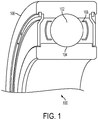
- FIG. 1 a cross-sectional perspective view of a bearing assembly 100 in accordance with the subject technology is shown.
- Heavy equipment such as bulldozers and a variety of other applications now known and later developed may advantageously utilize the subject technology for detecting wear of like bearing assemblies.
- the bearing assembly 100 is well-suited for use in aircraft electrical generators.
- the bearing assembly 100 includes bearings 102 mounted for movement in a track or race 104 formed by an enclosure 106.
- the enclosure 106 also houses a ball cage 108 that surrounds the bearings.
- the area surrounding the bearings 102 usually includes a lubricant such as grease.
- the grease may be maintained in place by seals (not shown).
- the bearings 102 are shown as balls but may be cylinders, rollers and the like.
- FIG. 2 a schematic representation of an electromechanical fuse 110 coupled to a bearing sensing circuit 112 in accordance with the subject technology is shown.
- the electro-mechanical fuse 110 is integrated into the enclosure 102 of the bearing assembly 100 as described below with respect to Figure 3 .
- the electro-mechanical fuse 110 provides continuity to the bearing sensing circuit 112.
- the bearing sensing circuit 112 outputs a signal indicating the wear condition of the bearing assembly 100 is acceptable.
- the signal may ultimately reach the aircraft pilot as an affirmative indication of acceptable parameters or simply the lack of an indication of operational issues and the like.
- the race 104 and ball cage 108 are particularly susceptible to damage because the bearings 102 are usually a relatively harder material.
- deformation of the ball cage 108 or even loose debris resulting from portions of the ball cage 108 breaking loose can create a damaging force on the electro-mechanical fuse 110.
- the damage causes the electro-mechanical fuse 110 to be broken, e.g., the fuse 100 opens.
- electrical continuity with the bearing sensing circuit 112 is lost and the bearing sensing circuit 112 generates a signal indicating bearing wear.
- damage to other generator components is greatly reduced because the generator is removed for maintenance in a timely manner.
- the electro-mechanical fuse 110 may be located in a plurality of different locations such as for example on one or more seals instead of or in addition to being located within the enclosure 102.
- the bearing enclosure component 114 may be an integral part of the enclosure 106 of the bearing assembly 100 or formed as a subcomponent of the bearing enclosure 106 as shown. As shown, the bearing enclosure component 114 is a subcomponent that forms a wall of the bearing enclosure 106.
- the bearing enclosure component 114 has a thin annular disc 116 bonded thereto. In one embodiment, the annular disc 116 is made from ceramic such that the disc 116 is relatively fragile. The ceramic disc 116 is bonded to the bearing enclosure component such that the ceramic disc 116 is at an inside surface of the enclosure 106 at the same radial location as the ball cage 108.
- a thin layer 118 of conductive material is fixed to the disc 116 to provide electrical continuity within the bearing sensing circuit 112.
- the thin layer 118 is silver paste fired onto the disc 116 before bonding to the enclosure component 114.
- the thin layer 118 is arcuate so that a gap 120 forms between two ends 122 thereof.
- Two thin leads (not shown) pass through holes 124 in the bearing enclosure component 114 to electrically attach to the ends 122, respectively.
- the leads are soldered to the thin layer 118 on one end and routed outside the enclosure 106 to connect to the bearing sensing circuit 112 on the other end.
- the thin layer 118 completes the bearing sensing circuit 112.
- the bearing sensing circuit 112 generates a signal or lack of a signal, as the case may be, indicating normal conditions.
- debris breaks the fragile disc 116.
- the electrical continuity of the thin layer 118 is broken. The loss of electrical continuity causes a bearing wear indication signal to be generated by the bearing sensing circuit 112.
- the subject technology is easily applied to bearings that are not floating. On bearings that float, some restriction of bearing rotation is preferable so that the thin layer 118 does not open under normal precession of the bearings 102.
- the anti-rotation may be an anti-rotation pin with low shear strength so that the anti-rotation aspects could be easily overridden by abnormally high rotational forces such as those caused by increased rotational torque in the main bearing.
- the subject technology is applicable to use in any type of bearing assembly with significant advantages for aircraft electrical generator applications.
- the functions of several elements may, in alternative embodiments, be carried out by fewer elements, or a single element.
- any functional element may perform fewer, or different, operations than those described with respect to the illustrated embodiment.
- functional elements shown as distinct for purposes of illustration may be incorporated within other functional elements, separated in different hardware or distributed in various ways in a particular implementation. Further, relative size and location are merely somewhat schematic and it is understood that not only the same but many other embodiments could have varying depictions.
Landscapes
- Engineering & Computer Science (AREA)
- General Engineering & Computer Science (AREA)
- Mechanical Engineering (AREA)
- Physics & Mathematics (AREA)
- General Physics & Mathematics (AREA)
- Rolling Contact Bearings (AREA)
Description
- The subject disclosure relates to bearing enclosures with wear detection, and more particularly to an improved wear detection mechanism based on sensing a damaged ball cage.
- In aircraft and other applications, generator designs commonly use life lubricated deep groove ball bearings to support rotor loads. The bearings are also replaced at established intervals to avoid costly repairs and or malfunctions. A typical DC air cooled generator often has auxiliary bearing systems to prevent potentially catastrophic failure. The auxiliary bearing supports the rotor load after the main bearing has failed.
- Systems are designed such that a bearing failure sensor alerts the flight crew that wear has been detected in the main bearing. Under current guidelines, the airline may continue revenue flight operations for a limited number of hours from the alert, after which the generator must be removed for bearing replacement. One advantage of the auxiliary bearing system for the aircraft operator is to avoid dispatch delays caused by a generator bearing failure and the immediate need for aircraft maintenance.
- There are problems associated with prior art bearing wear detection systems. Prior art systems, such as the system described in document
US2009208159 , rely on recognizing increase in radial play due to bearing wear. For preloaded bearings, determining the radial play is difficult and inexact, which often results in delay in bearing wear detection. Further, the prior art technology was acceptable for steel ball bearing designs since the steel balls progressively wear creating the radial play in advance of catastrophic ball cage damage. However, ceramic ball bearing designs wear differently, which prevents these methods from being optimal. - It is desirable to use ceramic balls in the main bearings because ceramic balls increase the life of the bearing. Although the ceramic balls are very robust, the other components may stop to function properly causing failure. A common failure mode of a ceramic deep groove ball bearing is that the grease degrades which causes the ball cage to fail from dynamic instability. Eventually parts of the ball cage are expelled from the bearing. It is noteworthy that because the bearing is preloaded, the ball cage failure does not result in a significant increase in radial play. Thus, cage damage may go undetected for some time. Frequently, as radial play increases, the gathered balls bind the inner ring and outer ring which normally causes the outer ring to rotate in the bearing liner bore. Continuous operation under these conditions causes damage to generator components and also imparts heat and high loading on the auxiliary bearing. As the bearing reaches the end of usefulness, radial play increases only after the cage has been consumed and considerable wear occurs on the inner and outer rings of the bearing. Examples of bearing wear detection systems are shown in
U.S. Patent No. 6,100,809 issued on August 8, 2000 to Novoselsky et al. andU.S. Patent No. 6,119,504 issued on September 19, 2000 to Claus . - There is a need, therefore, for an improved bearing enclosure which avoids delay in detection of ceramic ball main bearing failure. As a result, detection of an impending bearing failure is improved. Since deformation of the ball cage and/or portions of the ball cage breaking loose are an indication of bearing enclosure damage, the subject technology senses ball cage damage early to accomplish the early wear detection.
- In some applications, the subject technology also alleviates and may even eliminate the need for auxiliary bearings since the ceramic ball bearing may function for a significant period of time after grease depletion and the initiation of cage damage. If this period of reliable operation (with cage damage) is greater than the period normally expected by aircraft operators (approximately 20 hours) then the auxiliary bearing may not be necessary. In one embodiment, the sensor for determining cage deformation is integrated into the bearing. Thus, the overall bill of materials for the generator is reduced.
- Another embodiment of the subject technology is directed to an electromechanical fuse integrated into the enclosure or seal of a bearing assembly. The enclosure is an integrated part of the bearing assembly and is installed after the grease operation. Under normal operation, the electro-mechanical fuse provides continuity through a bearing sensing circuit. Ball cage damage causes the fuse to open and, in turn, the bearing sensing circuit indicates bearing wear. Thus, damage to other generator components is greatly reduced because the generator is removed for maintenance in a timely manner.
- Still another embodiment is directed to a bearing assembly including a bearing enclosure with bearings mounted for movement in a race formed by the bearing enclosure. A ball cage is within the bearing enclosure and surrounds the bearings. A fuse couples to the bearing enclosure and a bearing sensing circuit couples to the fuse. Under normal operation, the electro-mechanical fuse provides continuity to the bearing sensing circuit. Under operation after bearing wear, the fuse breaks such that the bearing sensing circuit generates a signal indicating bearing wear. The fuse may be an annular disc and a thin layer of conductive material fixed to the disc to provide electrical continuity within the bearing sensing circuit. The annular disc is ceramic and the thin layer is silver paste. The annular disc is preferably bonded to an inside surface of the bearing enclosure at a radial location approximately equal to a radial location of the ball cage.
- Yet another embodiment is directed to a bearing wear detection assembly including an electro-mechanical fuse including a disc with a conductive portion, and a bearing sensing circuit connected to the electro-mechanical fuse such that when the fuse opens, the bearing sensing circuit generates a signal indicating bearing wear. Preferably, the disc is ceramic and the conductive portion is a thin layer of silver paste. The thin layer may be arcuate so that a gap forms between two ends thereof. Leads connect to each end, respectively, for completing an electrical connection to the bearing sensing circuit. The disc may be bonded to an inside surface of a bearing assembly enclosure at a radial location approximately equal to a radial location of a ball cage surrounding bearings.
- It should be appreciated that the present technology can be implemented and utilized in numerous ways, including without limitation as an apparatus, a system and a device for applications now known and later developed within the scope of the appended claims. These and other unique features of the system disclosed herein will become more readily apparent from the following description and the accompanying drawings.
- So that those having ordinary skill in the art to which the disclosed system appertains will more readily understand how to make and use the same, reference may be had to the following drawings.
-
Figure 1 is a cross-sectional perspective view of a bearing assembly in accordance with the subject technology. -
Figure 2 is a schematic representation of a bearing sensing circuit with a fuse in accordance with the subject technology. -
Figure 3 is a perspective view of a bearing enclosure component having an electro-mechanical fuse in accordance with the subject technology. - The present disclosure overcomes many of the prior art problems associated with bearing wear detection systems. The advantages, and other features of the technology disclosed herein, will become more readily apparent to those having ordinary skill in the art from the following detailed description of certain preferred embodiments taken in conjunction with the drawings which set forth representative embodiments of the present invention and wherein like reference numerals identify similar structural elements.
- Unless otherwise specified, the illustrated embodiments can be understood as providing exemplary features of varying detail of certain embodiments, and therefore, unless otherwise specified, features, components, modules, elements, and/or aspects of the illustrations can be otherwise combined, interconnected, sequenced, separated, interchanged, positioned, and/or rearranged without materially departing from the disclosed systems or methods. Additionally, the shapes and sizes of components are also exemplary and unless otherwise specified, can be altered without materially affecting or limiting the disclosed technology.
- Now referring to
Figure 1 , a cross-sectional perspective view of a bearingassembly 100 in accordance with the subject technology is shown. Heavy equipment such as bulldozers and a variety of other applications now known and later developed may advantageously utilize the subject technology for detecting wear of like bearing assemblies. The bearingassembly 100 is well-suited for use in aircraft electrical generators. - The bearing
assembly 100 includesbearings 102 mounted for movement in a track orrace 104 formed by anenclosure 106. Theenclosure 106 also houses aball cage 108 that surrounds the bearings. The area surrounding thebearings 102 usually includes a lubricant such as grease. The grease may be maintained in place by seals (not shown). Thebearings 102 are shown as balls but may be cylinders, rollers and the like. - Referring now to
Figure 2 , a schematic representation of anelectromechanical fuse 110 coupled to abearing sensing circuit 112 in accordance with the subject technology is shown. The electro-mechanical fuse 110 is integrated into theenclosure 102 of the bearingassembly 100 as described below with respect toFigure 3 . Under normal operation, the electro-mechanical fuse 110 provides continuity to thebearing sensing circuit 112. In other words, when the electro-mechanical fuse 110 is intact and electrically coupled to thebearing sensing circuit 112, the bearingsensing circuit 112 outputs a signal indicating the wear condition of the bearingassembly 100 is acceptable. The signal may ultimately reach the aircraft pilot as an affirmative indication of acceptable parameters or simply the lack of an indication of operational issues and the like. - Referring again to
Figure 1 , as the bearingassembly 100 wears, pitting and fragmentation of the components occurs. Therace 104 andball cage 108 are particularly susceptible to damage because thebearings 102 are usually a relatively harder material. For example, deformation of theball cage 108 or even loose debris resulting from portions of theball cage 108 breaking loose can create a damaging force on the electro-mechanical fuse 110. The damage causes the electro-mechanical fuse 110 to be broken, e.g., thefuse 100 opens. As a result, electrical continuity with the bearingsensing circuit 112 is lost and the bearingsensing circuit 112 generates a signal indicating bearing wear. Thus, damage to other generator components is greatly reduced because the generator is removed for maintenance in a timely manner. The electro-mechanical fuse 110 may be located in a plurality of different locations such as for example on one or more seals instead of or in addition to being located within theenclosure 102. - Referring now to
Figure 3 , a perspective view of a bearingenclosure component 114 having an electro-mechanical fuse 110 in accordance with the subject technology is shown. The bearingenclosure component 114 may be an integral part of theenclosure 106 of the bearingassembly 100 or formed as a subcomponent of the bearingenclosure 106 as shown. As shown, the bearingenclosure component 114 is a subcomponent that forms a wall of the bearingenclosure 106. The bearingenclosure component 114 has a thinannular disc 116 bonded thereto. In one embodiment, theannular disc 116 is made from ceramic such that thedisc 116 is relatively fragile. Theceramic disc 116 is bonded to the bearing enclosure component such that theceramic disc 116 is at an inside surface of theenclosure 106 at the same radial location as theball cage 108. - A
thin layer 118 of conductive material is fixed to thedisc 116 to provide electrical continuity within the bearingsensing circuit 112. Preferably, thethin layer 118 is silver paste fired onto thedisc 116 before bonding to theenclosure component 114. Thethin layer 118 is arcuate so that agap 120 forms between twoends 122 thereof. Two thin leads (not shown) pass throughholes 124 in the bearingenclosure component 114 to electrically attach to theends 122, respectively. The leads are soldered to thethin layer 118 on one end and routed outside theenclosure 106 to connect to thebearing sensing circuit 112 on the other end. - As noted above, during normal operation, the
thin layer 118 completes the bearingsensing circuit 112. In this condition, the bearingsensing circuit 112 generates a signal or lack of a signal, as the case may be, indicating normal conditions. However, as wear occurs and the bearingcage 108 and/or other components fail, debris breaks thefragile disc 116. As a result, the electrical continuity of thethin layer 118 is broken. The loss of electrical continuity causes a bearing wear indication signal to be generated by the bearingsensing circuit 112. - The subject technology is easily applied to bearings that are not floating. On bearings that float, some restriction of bearing rotation is preferable so that the
thin layer 118 does not open under normal precession of thebearings 102. The anti-rotation may be an anti-rotation pin with low shear strength so that the anti-rotation aspects could be easily overridden by abnormally high rotational forces such as those caused by increased rotational torque in the main bearing. - As would be appreciated by those of ordinary skill in the pertinent art, the subject technology is applicable to use in any type of bearing assembly with significant advantages for aircraft electrical generator applications. The functions of several elements may, in alternative embodiments, be carried out by fewer elements, or a single element. Similarly, in some embodiments, any functional element may perform fewer, or different, operations than those described with respect to the illustrated embodiment. Also, functional elements shown as distinct for purposes of illustration may be incorporated within other functional elements, separated in different hardware or distributed in various ways in a particular implementation.
Further, relative size and location are merely somewhat schematic and it is understood that not only the same but many other embodiments could have varying depictions. - While the invention has been described with respect to preferred embodiments, those skilled in the art will readily appreciate that various changes and/or modifications can be made to the invention without departing from the scope of the invention as defined by the appended claims.
Claims (12)
- A bearing wear detection assembly (100) comprising:- a bearing enclosure (106); and- a fuse (110) including a disc (116) with a conductive portion (118),characterized in that the bearing wear detection assembly includes a ball cage (108) mounted with the bearing enclosure and surrounding bearings (102),
and in that the fuse is mounted to the bearing enclosure at a radial location approximately equal to a radial location of the ball cage such that as the bearings wear, the ball cage (108) generates debris that break the disk (116) and, in turn, disrupt electrical continuity in the conductive portion (118). - A bearing wear detection assembly as recited in Claim 1, further comprising a bearing sensing circuit (112) connected to the conductive portion (118) such that when the electrical continuity is disrupted, the bearing sensing circuit generates a signal indicating bearing wear.
- A bearing wear detection assembly as recited in Claim 1, wherein the disc (116) is made from ceramic, the conductive portion is a thin layer (118) of silver paste, and the bearings (102) are ceramic balls.
- A bearing wear detection assembly as recited in Claim 1, further comprising an anti-rotation pin for restricting bearing rotation.
- A bearing wear detection assembly as recited in Claim 1, wherein the fuse is an electro-mechanical fuse (110), and further including a bearing sensing circuit (112) coupled to the electro-mechanical fuse, wherein under normal operation, the electro-mechanical fuse provides continuity to the bearing sensing circuit, and under operation after bearing wear, the fuse is disrupted such that the bearing sensing circuit generates a signal indicating bearing wear.
- A bearing wear detection assembly as recited in Claim 5, wherein the disc (116) is a fragile annular disc and the conductive portion (118) is a thin layer of conductive material fixed to the fragile annular disc to provide electrical continuity within the bearing sensing circuit (112).
- A bearing wear detection assembly as recited in Claim 6, wherein the annular disc (116) is ceramic and the thin layer (118) is silver paste.
- A bearing wear detection assembly as recited in Claim 6, wherein the annular disc (116) is bonded to an inside surface of the bearing enclosure (106) at a radial location approximately equal to a radial location of the ball cage (108).
- A bearing wear detection assembly as recited in Claim 5, wherein the bearings (102) are not floating.
- A bearing wear detection assembly as recited in Claim 3 or 6, wherein the thin layer (118) is arcuate so that a gap (120) forms between two ends (122) thereof and further comprising leads connected to each end (122), respectively, for completing an electrical connection to the bearing sensing circuit (112).
- A bearing wear detection assembly as recited in Claim 5, wherein the bearings
(102) are floating, and further comprising means for restricting bearing rotation. - A bearing wear detection assembly as recited in Claim 11, wherein the means for
restricting is an anti-rotation pin.
Applications Claiming Priority (2)
| Application Number | Priority Date | Filing Date | Title |
|---|---|---|---|
| US12/956,308 US8876393B2 (en) | 2010-11-30 | 2010-11-30 | Bearing enclosure with integrated wear detection |
| PCT/US2011/062006 WO2012074867A1 (en) | 2010-11-30 | 2011-11-23 | Bearing enclosure with integrated wear detection |
Publications (2)
| Publication Number | Publication Date |
|---|---|
| EP2646699A1 EP2646699A1 (en) | 2013-10-09 |
| EP2646699B1 true EP2646699B1 (en) | 2017-01-25 |
Family
ID=45349564
Family Applications (1)
| Application Number | Title | Priority Date | Filing Date |
|---|---|---|---|
| EP11797069.9A Active EP2646699B1 (en) | 2010-11-30 | 2011-11-23 | Bearing wear detection assembly |
Country Status (3)
| Country | Link |
|---|---|
| US (1) | US8876393B2 (en) |
| EP (1) | EP2646699B1 (en) |
| WO (1) | WO2012074867A1 (en) |
Families Citing this family (5)
| Publication number | Priority date | Publication date | Assignee | Title |
|---|---|---|---|---|
| US8002472B2 (en) * | 2008-06-30 | 2011-08-23 | Nucor Corporation | Slew bearing system |
| US9115761B2 (en) | 2013-06-03 | 2015-08-25 | Honeywell International Inc. | Ball bearing assembly notification mechanism |
| US20160160925A1 (en) * | 2014-12-04 | 2016-06-09 | Schaeffler Technologies AG & Co. KG | Rolling bearing assembly with carbon fiber seal |
| JP6602645B2 (en) * | 2015-11-02 | 2019-11-06 | ニッタ株式会社 | Sealing material fixing structure |
| US11453487B2 (en) * | 2018-06-28 | 2022-09-27 | Sikorsky Aircraft Corporation | Redundant helicopter pitch change bearing |
Family Cites Families (13)
| Publication number | Priority date | Publication date | Assignee | Title |
|---|---|---|---|---|
| AT279281B (en) * | 1968-02-23 | 1970-02-25 | Man Turbo Gmbh | Axially braced bearings, especially for high-speed shafts |
| US3999376A (en) * | 1973-07-05 | 1976-12-28 | Ford Motor Company | One-piece ceramic support housing for a gas turbine with a rotary regenerator |
| FR2706956B1 (en) * | 1993-06-25 | 1995-08-18 | Roulements Soc Nouvelle | |
| DE19755000C1 (en) | 1997-12-11 | 1999-03-04 | Krupp Ag Hoesch Krupp | Wear measuring device for roller bearing |
| US6100809A (en) | 1998-11-24 | 2000-08-08 | Alliedsignal Inc. | Bearing wear detection system |
| EP1203960B2 (en) * | 2000-11-06 | 2018-02-07 | Nsk Ltd | Rolling bearing device and ring with sensor for the rolling bearing device |
| FR2823273B1 (en) * | 2001-04-06 | 2003-07-18 | Roulements Soc Nouvelle | BEARING PROVIDED WITH A SENSOR ASSEMBLY SHEATH |
| DE10323889A1 (en) * | 2003-05-27 | 2004-12-16 | Ehrfeld Mikrotechnik Ag | Rolling bearings with polymer electronics |
| JP2005315269A (en) * | 2004-04-26 | 2005-11-10 | Honda Motor Co Ltd | Bearing structure |
| JP2005344842A (en) | 2004-06-03 | 2005-12-15 | Nsk Ltd | Monitor and monitoring method |
| JP2006010477A (en) * | 2004-06-25 | 2006-01-12 | Ntn Corp | Bearing device for wheel with built-in load sensor |
| EP1816458B1 (en) * | 2004-11-24 | 2013-03-06 | JTEKT Corporation | Sensor device and rolling bearing with sensor |
| DE102008009283B4 (en) * | 2008-02-15 | 2021-07-29 | Schaeffler Technologies AG & Co. KG | Wheel bearing device for a motor vehicle |
-
2010
- 2010-11-30 US US12/956,308 patent/US8876393B2/en not_active Expired - Fee Related
-
2011
- 2011-11-23 EP EP11797069.9A patent/EP2646699B1/en active Active
- 2011-11-23 WO PCT/US2011/062006 patent/WO2012074867A1/en active Application Filing
Non-Patent Citations (1)
| Title |
|---|
| None * |
Also Published As
| Publication number | Publication date |
|---|---|
| US8876393B2 (en) | 2014-11-04 |
| EP2646699A1 (en) | 2013-10-09 |
| WO2012074867A1 (en) | 2012-06-07 |
| US20120134612A1 (en) | 2012-05-31 |
Similar Documents
| Publication | Publication Date | Title |
|---|---|---|
| EP2646699B1 (en) | Bearing wear detection assembly | |
| CA2884602C (en) | Rotary machine, bearing and method for manufacturing a rotary machine | |
| US5642944A (en) | Auxiliary bearing system | |
| CN101344036B (en) | Turbo engine | |
| EP1022438B1 (en) | Method and apparatus for supporting a rotatable shaft within a gas turbine engine | |
| CN105431638B (en) | Rotating machinery with least one Active Magnetic Bearing and auxiliary rolling bearing | |
| US9359073B2 (en) | Aircraft tail rotor system | |
| US5998894A (en) | Modular bearing failure sensor for an electrical generator | |
| EP3004653B1 (en) | Rotating machine with at least one active magnetic bearing and spaced auxiliary rolling bearings | |
| CN108119542B (en) | Landing bearing assembly and rotary machine equipped with such an assembly | |
| EP3266709B1 (en) | Bearing monitoring system for an air cycle machine and method of monitoring | |
| EP3211306B1 (en) | System and method for monitoring bearing health in a journal assembly | |
| IL204213A (en) | Overload detection | |
| EP2412080B1 (en) | Bearing assembly | |
| US8622699B2 (en) | Device adapted to be fitted with propeller blades | |
| US20150078808A1 (en) | Rod end wear prevention | |
| US6413048B1 (en) | Elastomeric bearing | |
| US11807354B2 (en) | Gearbox and associated aircraft | |
| EP3530972B1 (en) | Shaft shear section | |
| WO2008069708A1 (en) | Bearing component and bearing arrangement comprising the bearing component |
Legal Events
| Date | Code | Title | Description |
|---|---|---|---|
| PUAI | Public reference made under article 153(3) epc to a published international application that has entered the european phase |
Free format text: ORIGINAL CODE: 0009012 |
|
| 17P | Request for examination filed |
Effective date: 20130621 |
|
| AK | Designated contracting states |
Kind code of ref document: A1 Designated state(s): AL AT BE BG CH CY CZ DE DK EE ES FI FR GB GR HR HU IE IS IT LI LT LU LV MC MK MT NL NO PL PT RO RS SE SI SK SM TR |
|
| DAX | Request for extension of the european patent (deleted) | ||
| RAP1 | Party data changed (applicant data changed or rights of an application transferred) |
Owner name: SAFRAN POWER UK LTD. |
|
| 17Q | First examination report despatched |
Effective date: 20160301 |
|
| RIC1 | Information provided on ipc code assigned before grant |
Ipc: G01B 7/14 20060101ALI20160704BHEP Ipc: F16C 33/78 20060101ALI20160704BHEP Ipc: F16C 19/52 20060101AFI20160704BHEP |
|
| GRAP | Despatch of communication of intention to grant a patent |
Free format text: ORIGINAL CODE: EPIDOSNIGR1 |
|
| INTG | Intention to grant announced |
Effective date: 20160819 |
|
| STAA | Information on the status of an ep patent application or granted ep patent |
Free format text: STATUS: GRANT OF PATENT IS INTENDED |
|
| GRAS | Grant fee paid |
Free format text: ORIGINAL CODE: EPIDOSNIGR3 |
|
| GRAA | (expected) grant |
Free format text: ORIGINAL CODE: 0009210 |
|
| STAA | Information on the status of an ep patent application or granted ep patent |
Free format text: STATUS: THE PATENT HAS BEEN GRANTED |
|
| AK | Designated contracting states |
Kind code of ref document: B1 Designated state(s): AL AT BE BG CH CY CZ DE DK EE ES FI FR GB GR HR HU IE IS IT LI LT LU LV MC MK MT NL NO PL PT RO RS SE SI SK SM TR |
|
| REG | Reference to a national code |
Ref country code: GB Ref legal event code: FG4D |
|
| REG | Reference to a national code |
Ref country code: CH Ref legal event code: EP |
|
| REG | Reference to a national code |
Ref country code: AT Ref legal event code: REF Ref document number: 864337 Country of ref document: AT Kind code of ref document: T Effective date: 20170215 |
|
| REG | Reference to a national code |
Ref country code: IE Ref legal event code: FG4D |
|
| REG | Reference to a national code |
Ref country code: DE Ref legal event code: R096 Ref document number: 602011034718 Country of ref document: DE |
|
| REG | Reference to a national code |
Ref country code: LT Ref legal event code: MG4D |
|
| REG | Reference to a national code |
Ref country code: NL Ref legal event code: MP Effective date: 20170125 |
|
| REG | Reference to a national code |
Ref country code: AT Ref legal event code: MK05 Ref document number: 864337 Country of ref document: AT Kind code of ref document: T Effective date: 20170125 |
|
| PG25 | Lapsed in a contracting state [announced via postgrant information from national office to epo] |
Ref country code: NL Free format text: LAPSE BECAUSE OF FAILURE TO SUBMIT A TRANSLATION OF THE DESCRIPTION OR TO PAY THE FEE WITHIN THE PRESCRIBED TIME-LIMIT Effective date: 20170125 |
|
| PG25 | Lapsed in a contracting state [announced via postgrant information from national office to epo] |
Ref country code: GR Free format text: LAPSE BECAUSE OF FAILURE TO SUBMIT A TRANSLATION OF THE DESCRIPTION OR TO PAY THE FEE WITHIN THE PRESCRIBED TIME-LIMIT Effective date: 20170426 Ref country code: LT Free format text: LAPSE BECAUSE OF FAILURE TO SUBMIT A TRANSLATION OF THE DESCRIPTION OR TO PAY THE FEE WITHIN THE PRESCRIBED TIME-LIMIT Effective date: 20170125 Ref country code: FI Free format text: LAPSE BECAUSE OF FAILURE TO SUBMIT A TRANSLATION OF THE DESCRIPTION OR TO PAY THE FEE WITHIN THE PRESCRIBED TIME-LIMIT Effective date: 20170125 Ref country code: IS Free format text: LAPSE BECAUSE OF FAILURE TO SUBMIT A TRANSLATION OF THE DESCRIPTION OR TO PAY THE FEE WITHIN THE PRESCRIBED TIME-LIMIT Effective date: 20170525 Ref country code: HR Free format text: LAPSE BECAUSE OF FAILURE TO SUBMIT A TRANSLATION OF THE DESCRIPTION OR TO PAY THE FEE WITHIN THE PRESCRIBED TIME-LIMIT Effective date: 20170125 Ref country code: NO Free format text: LAPSE BECAUSE OF FAILURE TO SUBMIT A TRANSLATION OF THE DESCRIPTION OR TO PAY THE FEE WITHIN THE PRESCRIBED TIME-LIMIT Effective date: 20170425 |
|
| PG25 | Lapsed in a contracting state [announced via postgrant information from national office to epo] |
Ref country code: BG Free format text: LAPSE BECAUSE OF FAILURE TO SUBMIT A TRANSLATION OF THE DESCRIPTION OR TO PAY THE FEE WITHIN THE PRESCRIBED TIME-LIMIT Effective date: 20170425 Ref country code: PT Free format text: LAPSE BECAUSE OF FAILURE TO SUBMIT A TRANSLATION OF THE DESCRIPTION OR TO PAY THE FEE WITHIN THE PRESCRIBED TIME-LIMIT Effective date: 20170525 Ref country code: RS Free format text: LAPSE BECAUSE OF FAILURE TO SUBMIT A TRANSLATION OF THE DESCRIPTION OR TO PAY THE FEE WITHIN THE PRESCRIBED TIME-LIMIT Effective date: 20170125 Ref country code: AT Free format text: LAPSE BECAUSE OF FAILURE TO SUBMIT A TRANSLATION OF THE DESCRIPTION OR TO PAY THE FEE WITHIN THE PRESCRIBED TIME-LIMIT Effective date: 20170125 Ref country code: LV Free format text: LAPSE BECAUSE OF FAILURE TO SUBMIT A TRANSLATION OF THE DESCRIPTION OR TO PAY THE FEE WITHIN THE PRESCRIBED TIME-LIMIT Effective date: 20170125 Ref country code: ES Free format text: LAPSE BECAUSE OF FAILURE TO SUBMIT A TRANSLATION OF THE DESCRIPTION OR TO PAY THE FEE WITHIN THE PRESCRIBED TIME-LIMIT Effective date: 20170125 Ref country code: PL Free format text: LAPSE BECAUSE OF FAILURE TO SUBMIT A TRANSLATION OF THE DESCRIPTION OR TO PAY THE FEE WITHIN THE PRESCRIBED TIME-LIMIT Effective date: 20170125 Ref country code: SE Free format text: LAPSE BECAUSE OF FAILURE TO SUBMIT A TRANSLATION OF THE DESCRIPTION OR TO PAY THE FEE WITHIN THE PRESCRIBED TIME-LIMIT Effective date: 20170125 |
|
| REG | Reference to a national code |
Ref country code: FR Ref legal event code: PLFP Year of fee payment: 7 |
|
| REG | Reference to a national code |
Ref country code: DE Ref legal event code: R097 Ref document number: 602011034718 Country of ref document: DE |
|
| PG25 | Lapsed in a contracting state [announced via postgrant information from national office to epo] |
Ref country code: IT Free format text: LAPSE BECAUSE OF FAILURE TO SUBMIT A TRANSLATION OF THE DESCRIPTION OR TO PAY THE FEE WITHIN THE PRESCRIBED TIME-LIMIT Effective date: 20170125 Ref country code: CZ Free format text: LAPSE BECAUSE OF FAILURE TO SUBMIT A TRANSLATION OF THE DESCRIPTION OR TO PAY THE FEE WITHIN THE PRESCRIBED TIME-LIMIT Effective date: 20170125 Ref country code: RO Free format text: LAPSE BECAUSE OF FAILURE TO SUBMIT A TRANSLATION OF THE DESCRIPTION OR TO PAY THE FEE WITHIN THE PRESCRIBED TIME-LIMIT Effective date: 20170125 Ref country code: SK Free format text: LAPSE BECAUSE OF FAILURE TO SUBMIT A TRANSLATION OF THE DESCRIPTION OR TO PAY THE FEE WITHIN THE PRESCRIBED TIME-LIMIT Effective date: 20170125 Ref country code: EE Free format text: LAPSE BECAUSE OF FAILURE TO SUBMIT A TRANSLATION OF THE DESCRIPTION OR TO PAY THE FEE WITHIN THE PRESCRIBED TIME-LIMIT Effective date: 20170125 |
|
| PG25 | Lapsed in a contracting state [announced via postgrant information from national office to epo] |
Ref country code: DK Free format text: LAPSE BECAUSE OF FAILURE TO SUBMIT A TRANSLATION OF THE DESCRIPTION OR TO PAY THE FEE WITHIN THE PRESCRIBED TIME-LIMIT Effective date: 20170125 Ref country code: SM Free format text: LAPSE BECAUSE OF FAILURE TO SUBMIT A TRANSLATION OF THE DESCRIPTION OR TO PAY THE FEE WITHIN THE PRESCRIBED TIME-LIMIT Effective date: 20170125 |
|
| PLBE | No opposition filed within time limit |
Free format text: ORIGINAL CODE: 0009261 |
|
| STAA | Information on the status of an ep patent application or granted ep patent |
Free format text: STATUS: NO OPPOSITION FILED WITHIN TIME LIMIT |
|
| 26N | No opposition filed |
Effective date: 20171026 |
|
| PG25 | Lapsed in a contracting state [announced via postgrant information from national office to epo] |
Ref country code: SI Free format text: LAPSE BECAUSE OF FAILURE TO SUBMIT A TRANSLATION OF THE DESCRIPTION OR TO PAY THE FEE WITHIN THE PRESCRIBED TIME-LIMIT Effective date: 20170125 |
|
| PG25 | Lapsed in a contracting state [announced via postgrant information from national office to epo] |
Ref country code: MC Free format text: LAPSE BECAUSE OF FAILURE TO SUBMIT A TRANSLATION OF THE DESCRIPTION OR TO PAY THE FEE WITHIN THE PRESCRIBED TIME-LIMIT Effective date: 20170125 |
|
| PG25 | Lapsed in a contracting state [announced via postgrant information from national office to epo] |
Ref country code: CH Free format text: LAPSE BECAUSE OF NON-PAYMENT OF DUE FEES Effective date: 20171130 Ref country code: LI Free format text: LAPSE BECAUSE OF NON-PAYMENT OF DUE FEES Effective date: 20171130 |
|
| PG25 | Lapsed in a contracting state [announced via postgrant information from national office to epo] |
Ref country code: LU Free format text: LAPSE BECAUSE OF NON-PAYMENT OF DUE FEES Effective date: 20171123 |
|
| REG | Reference to a national code |
Ref country code: BE Ref legal event code: MM Effective date: 20171130 |
|
| REG | Reference to a national code |
Ref country code: IE Ref legal event code: MM4A |
|
| PG25 | Lapsed in a contracting state [announced via postgrant information from national office to epo] |
Ref country code: MT Free format text: LAPSE BECAUSE OF NON-PAYMENT OF DUE FEES Effective date: 20171123 |
|
| REG | Reference to a national code |
Ref country code: FR Ref legal event code: PLFP Year of fee payment: 8 |
|
| PG25 | Lapsed in a contracting state [announced via postgrant information from national office to epo] |
Ref country code: IE Free format text: LAPSE BECAUSE OF NON-PAYMENT OF DUE FEES Effective date: 20171123 |
|
| PG25 | Lapsed in a contracting state [announced via postgrant information from national office to epo] |
Ref country code: BE Free format text: LAPSE BECAUSE OF NON-PAYMENT OF DUE FEES Effective date: 20171130 |
|
| PG25 | Lapsed in a contracting state [announced via postgrant information from national office to epo] |
Ref country code: HU Free format text: LAPSE BECAUSE OF FAILURE TO SUBMIT A TRANSLATION OF THE DESCRIPTION OR TO PAY THE FEE WITHIN THE PRESCRIBED TIME-LIMIT; INVALID AB INITIO Effective date: 20111123 |
|
| PG25 | Lapsed in a contracting state [announced via postgrant information from national office to epo] |
Ref country code: CY Free format text: LAPSE BECAUSE OF NON-PAYMENT OF DUE FEES Effective date: 20170125 |
|
| PG25 | Lapsed in a contracting state [announced via postgrant information from national office to epo] |
Ref country code: MK Free format text: LAPSE BECAUSE OF FAILURE TO SUBMIT A TRANSLATION OF THE DESCRIPTION OR TO PAY THE FEE WITHIN THE PRESCRIBED TIME-LIMIT Effective date: 20170125 |
|
| PG25 | Lapsed in a contracting state [announced via postgrant information from national office to epo] |
Ref country code: TR Free format text: LAPSE BECAUSE OF FAILURE TO SUBMIT A TRANSLATION OF THE DESCRIPTION OR TO PAY THE FEE WITHIN THE PRESCRIBED TIME-LIMIT Effective date: 20170125 |
|
| PG25 | Lapsed in a contracting state [announced via postgrant information from national office to epo] |
Ref country code: AL Free format text: LAPSE BECAUSE OF FAILURE TO SUBMIT A TRANSLATION OF THE DESCRIPTION OR TO PAY THE FEE WITHIN THE PRESCRIBED TIME-LIMIT Effective date: 20170125 |
|
| PGFP | Annual fee paid to national office [announced via postgrant information from national office to epo] |
Ref country code: DE Payment date: 20211020 Year of fee payment: 11 |
|
| REG | Reference to a national code |
Ref country code: DE Ref legal event code: R119 Ref document number: 602011034718 Country of ref document: DE |
|
| PG25 | Lapsed in a contracting state [announced via postgrant information from national office to epo] |
Ref country code: DE Free format text: LAPSE BECAUSE OF NON-PAYMENT OF DUE FEES Effective date: 20230601 |
|
| PGFP | Annual fee paid to national office [announced via postgrant information from national office to epo] |
Ref country code: GB Payment date: 20231019 Year of fee payment: 13 |
|
| PGFP | Annual fee paid to national office [announced via postgrant information from national office to epo] |
Ref country code: FR Payment date: 20231020 Year of fee payment: 13 |