EP2645741A1 - Corded audio device with wireless data exchange - Google Patents
Corded audio device with wireless data exchange Download PDFInfo
- Publication number
- EP2645741A1 EP2645741A1 EP12161542.1A EP12161542A EP2645741A1 EP 2645741 A1 EP2645741 A1 EP 2645741A1 EP 12161542 A EP12161542 A EP 12161542A EP 2645741 A1 EP2645741 A1 EP 2645741A1
- Authority
- EP
- European Patent Office
- Prior art keywords
- audio device
- housing
- connector
- speaker
- media player
- Prior art date
- Legal status (The legal status is an assumption and is not a legal conclusion. Google has not performed a legal analysis and makes no representation as to the accuracy of the status listed.)
- Withdrawn
Links
- 230000005236 sound signal Effects 0.000 claims abstract description 16
- 230000035945 sensitivity Effects 0.000 claims description 2
- 230000003213 activating effect Effects 0.000 description 3
- 230000004913 activation Effects 0.000 description 2
- 238000001514 detection method Methods 0.000 description 2
- 210000000613 ear canal Anatomy 0.000 description 2
- 238000003780 insertion Methods 0.000 description 2
- 230000037431 insertion Effects 0.000 description 2
- VTLYHLREPCPDKX-UHFFFAOYSA-N 1,2-dichloro-3-(2,3-dichlorophenyl)benzene Chemical compound ClC1=CC=CC(C=2C(=C(Cl)C=CC=2)Cl)=C1Cl VTLYHLREPCPDKX-UHFFFAOYSA-N 0.000 description 1
- ALFHIHDQSYXSGP-UHFFFAOYSA-N 1,2-dichloro-3-(2,4-dichlorophenyl)benzene Chemical compound ClC1=CC(Cl)=CC=C1C1=CC=CC(Cl)=C1Cl ALFHIHDQSYXSGP-UHFFFAOYSA-N 0.000 description 1
- 241000287828 Gallus gallus Species 0.000 description 1
- 230000005540 biological transmission Effects 0.000 description 1
- 230000000694 effects Effects 0.000 description 1
- 210000003128 head Anatomy 0.000 description 1
- 230000004044 response Effects 0.000 description 1
Images


Classifications
-
- H—ELECTRICITY
- H04—ELECTRIC COMMUNICATION TECHNIQUE
- H04R—LOUDSPEAKERS, MICROPHONES, GRAMOPHONE PICK-UPS OR LIKE ACOUSTIC ELECTROMECHANICAL TRANSDUCERS; DEAF-AID SETS; PUBLIC ADDRESS SYSTEMS
- H04R3/00—Circuits for transducers, loudspeakers or microphones
-
- H—ELECTRICITY
- H04—ELECTRIC COMMUNICATION TECHNIQUE
- H04R—LOUDSPEAKERS, MICROPHONES, GRAMOPHONE PICK-UPS OR LIKE ACOUSTIC ELECTROMECHANICAL TRANSDUCERS; DEAF-AID SETS; PUBLIC ADDRESS SYSTEMS
- H04R5/00—Stereophonic arrangements
- H04R5/033—Headphones for stereophonic communication
-
- H—ELECTRICITY
- H04—ELECTRIC COMMUNICATION TECHNIQUE
- H04R—LOUDSPEAKERS, MICROPHONES, GRAMOPHONE PICK-UPS OR LIKE ACOUSTIC ELECTROMECHANICAL TRANSDUCERS; DEAF-AID SETS; PUBLIC ADDRESS SYSTEMS
- H04R1/00—Details of transducers, loudspeakers or microphones
- H04R1/10—Earpieces; Attachments therefor ; Earphones; Monophonic headphones
- H04R1/1041—Mechanical or electronic switches, or control elements
-
- H—ELECTRICITY
- H04—ELECTRIC COMMUNICATION TECHNIQUE
- H04R—LOUDSPEAKERS, MICROPHONES, GRAMOPHONE PICK-UPS OR LIKE ACOUSTIC ELECTROMECHANICAL TRANSDUCERS; DEAF-AID SETS; PUBLIC ADDRESS SYSTEMS
- H04R2201/00—Details of transducers, loudspeakers or microphones covered by H04R1/00 but not provided for in any of its subgroups
- H04R2201/10—Details of earpieces, attachments therefor, earphones or monophonic headphones covered by H04R1/10 but not provided for in any of its subgroups
- H04R2201/103—Combination of monophonic or stereophonic headphones with audio players, e.g. integrated in the headphone
-
- H—ELECTRICITY
- H04—ELECTRIC COMMUNICATION TECHNIQUE
- H04R—LOUDSPEAKERS, MICROPHONES, GRAMOPHONE PICK-UPS OR LIKE ACOUSTIC ELECTROMECHANICAL TRANSDUCERS; DEAF-AID SETS; PUBLIC ADDRESS SYSTEMS
- H04R2430/00—Signal processing covered by H04R, not provided for in its groups
- H04R2430/01—Aspects of volume control, not necessarily automatic, in sound systems
-
- H—ELECTRICITY
- H04—ELECTRIC COMMUNICATION TECHNIQUE
- H04R—LOUDSPEAKERS, MICROPHONES, GRAMOPHONE PICK-UPS OR LIKE ACOUSTIC ELECTROMECHANICAL TRANSDUCERS; DEAF-AID SETS; PUBLIC ADDRESS SYSTEMS
- H04R2460/00—Details of hearing devices, i.e. of ear- or headphones covered by H04R1/10 or H04R5/033 but not provided for in any of their subgroups, or of hearing aids covered by H04R25/00 but not provided for in any of its subgroups
- H04R2460/03—Aspects of the reduction of energy consumption in hearing devices
Definitions
- the present invention relates to a corded audio device adapted for wireless data exchange with a media player or other communication device.
- Wireless audio devices using different wireless communication protocols such as Bluetooth, are known and require frequent recharging or exchange of batteries.
- a corded audio device comprising a first housing; a first speaker for converting an electronic signal into sound, the first speaker being accommodated in the first housing; a cord with a connector for connection to and receiving an audio signal from a media player, the cord being connected to the first speaker; and a radio unit comprising a radio transmitter for sending control information to the media player.
- the control information may comprise identification data of the audio device.
- the audio device according to the present invention may be used for media players or other communication devices from different manufacturers using different standards for control signals.
- the combination of a radio unit and a cord enables wireless reading of audio device identifier or other audio device parameters and at the same time allows for use of a simple standard connector for connecting the audio device to a media player or other communication device.
- the battery requirements for the audio device may be limited, since only control information is sent wirelessly and audio signals are received and/or sent on a wired connection.
- a more user-friendly audio device is provided since a user does not have to charge/replace batteries of the audio device on a regular basis.
- a media player or other communication device can adapt sound or audio parameters to the audio device based on an audio device identifier (identification data) and/or other control information from the audio device.
- the audio device may be headphones, earphones, speakerphones (conferencing devices) or a headset.
- the media player may be a music or film player, mobile phone, a smart phone with or without a touch screen, or a tablet computer.
- the audio device comprises a first housing and a first speaker or first speakers for converting an electronic signal into sound.
- the first speaker may be accommodated in the first housing.
- the first housing may accommodate a single first speaker or a plurality of first speakers, e.g. including a first primary speaker and a first secondary speaker.
- the audio device comprises a cord with a connector, e.g. for connection to and receiving an audio signal from a media player.
- the cord may comprise a primary part with a first end and a second end.
- the connector may be attached to the cord at the first end of the primary part.
- the cord may comprise one or more secondary parts, e.g. a first secondary part and/or a second secondary part, each having a first end and a second end.
- the cord may comprise a number of wires including a first wire and a second wire connecting one or more terminals of the connector to different parts of the audio device.
- the cord or parts thereof may be connected to the first speaker(s).
- the audio signal may be analog or digital.
- An analog audio signal from the media player may be fed directly to the first speaker(s) or a first speaker unit optionally including a filter unit.
- an analog or digital audio signal from the media player may be fed to a first processing unit a common processing unit between the connector and the first speaker(s).
- the cord may comprise at least one or a plurality of wires connected to respective terminals of the connector.
- the cord may comprise a first wire connected to a first connector terminal and/or a second wire connected to a second connector terminal.
- the number of wires and terminals may be limited, e.g. the cord may comprise less than 5 wires.
- the audio device comprises a radio unit comprising a radio transmitter for sending control information to the media player.
- the control information comprises identification data of the audio device.
- the identification data of the audio device may comprise one or more of speaker performance data, e.g. speaker frequency response and/or speaker impedance, model number data, user interface data, and speaker sensitivity data.
- the media player may then be configured for selecting one or more audio signal parameters of the audio signal based on the identification data of the audio device.
- the audio device may comprise a control unit incorporating the radio unit.
- a control unit may comprise a printed circuit board (PCB) with the radio unit mounted thereon.
- the radio unit may comprise or be constituted by a Bluetooth chip, such as a Blutooth Low Energy (BLE) Chip.
- the control unit may comprise one or more of at least one clock generator, an antenna and a memory.
- the antenna may be incorporated in the radio unit.
- the memory may store identification data of the audio device.
- the audio device may comprise first battery terminals connected to the radio unit, e.g. for feeding the radio unit and/or control unit. A first battery may be connected to or attached to the first battery terminals.
- the audio device may comprise a user interface enabling a user to provide user input to the audio device.
- the user interface may comprise one or more buttons, e.g. including a first button and optionally a second button. In one or more embodiments, the user interface has between two and ten buttons.
- the user interface may be connected to one or more input terminals of a control unit, e.g. directly to one or more input terminals of the radio unit or a BLE chip.
- the user interface may comprise a microphone and a voice command detection unit adapted for receiving and processing voice commands for voice control of the audio device.
- the user interface may comprise a connect button, where the audio device is adapted to send identification data of the audio device upon activation of the connect button.
- the audio device may be adapted to send control information to the media player based on the user input from the user interface.
- the radio unit may be adapted to send a first control signal when a first button of the user interface is activated or pressed.
- the radio unit may comprise one or more antennas.
- the audio device may be adapted to send different control signals to the media player, e.g. enabling a user to control the media player and operation thereof.
- the radio unit unit may be adapted for Bluetooth communication, e.g. according to the Bluetooth Low Energy (BLE) protocol.
- BLE Bluetooth Low Energy
- the audio device may comprise a control housing attached to the cord, wherein the user interface and/or the radio unit is/are arranged in the control housing.
- a control housing with user interface and radio unit attached to the cord may improve user friendliness of the audio device by facilitating user input during use.
- the control housing may be positioned at a distance from the first housing along the cord. The distance between the first housing and the control housing along the cord may be at least 5 cm, such as in the range from 5 cm to about 80 cm.
- the user interface and/or the radio unit may be arranged in the connector.
- a user interface and radio unit arranged in the connector may improve user friendliness of the audio device by facilitating user input during use.
- the user interface and/or the radio unit may be arranged in the first housing.
- a user interface and radio unit arranged in the first housing may provide a simple audio device with few complex parts, e.g. by incorporating movable parts into few or a single housing. This may lead to reduced assembly costs.
- the radio unit may comprise a radio receiver for receiving control information from the media player.
- the control information to the media player may comprise control data or different control signals for the media player, e.g. control data or control signals indicative of one or more of the following: “VOLUME UP”, “VOLUME DOWN”, “CONNECT”, “DISCONNECT”, “NEXT”, “PREVIOUS”, “PLAY/PAUSE”, “STOP”.
- the audio device may comprise one or more battery compartments for accommodating one or more batteries for delivering power to the audio device.
- the audio device may comprise a set of battery charge terminals for allowing recharging of at least a first battery and/or a second battery.
- the audio device may comprise a second housing and a second speaker or second speakers for converting an electronic signal into sound.
- the second speaker(s) may be accommodated in the second housing.
- the second may accommodate a single second speaker or a plurality of second speakers, e.g. including a second primary speaker and a second secondary speaker.
- the cord may be connected to the second speaker(s).
- An analog audio signal from the media player may be fed directly to the second speaker(s) or a second speaker unit optionally including a filter unit.
- an analog or digital audio signal from the media player may be fed to a second processing unit or to the common processing unit between the connector and the second speaker(s).
- the audio device may comprise second battery terminals, e.g. connected to processing unit, e.g. the first processing unit and/or the second processing unit. Second battery terminals may be connected to the common processing unit.
- the connector may be a two-terminal connector, a three-terminal connector, or a four-terminal connector. Accordingly, the number of terminals is relatively low, reducing the complexity of the connector.
- the audio device may be adapted for two-way audio communication. Accordingly, the audio device may comprise a microphone and the wherein the audio device may be configured for bi-directional or two-way audio communication via the cord.
- the audio device may be adapted to detect connection status of the connector, i.e. whether the connector is plugged into a media player or not, and send control information to the media player via the radio unit based on the connection status.
- the audio device may thus comprise a detector unit for detecting connection status and adapted for activating the radio unit by triggering sending of identification data.
- the radio unit is disabled when the connector is not connected as by the detector unit.
- Fig. 1 schematically shows an audio device according to the present invention.
- the audio device 2 comprises a first housing 4, a first speaker 6 for converting an electronic signal into sound, the first speaker 6 being accommodated in the first housing 4 as seen in Fig. 2 .
- the audio device 2 has a cord 8 with a primary part 8A having a first end with a connector 10 for connection to and receiving an audio signal from a media player 11, the cord 8 being connected to the first speaker 6.
- the audio device 2 comprises a radio unit 12 comprising a radio transmitter for sending control information to the media player 11 on a wireless connection 24, the control information comprising identification data of the audio device 2.
- the radio unit 12 is accommodated in the first housing 4 as seen in Fig. 2 .
- the audio device 2 comprises a second housing 14 accommodating a second speaker 16 as seen in Fig. 3 connected to the connector 10 via cord 8.
- the audio device may comprise a connecting band or device 17, such as a head band or neck band, connecting the first housing 4 and the second housing 14.
- a second secondary part part 8C may connect the second speaker 16 to the primary part 8A.
- Fig. 2 schematically illustrates an exemplary first housing 4 accommodating a first speaker 6.
- the first speaker 6 is connected to a first wire 18A and a second wire 18B of the primary part 8A of the cord 8.
- the wires 18A and 18B are connected to respective first and second terminals of the connector 10 for receiving an audio signal from a media player.
- the radio unit 12 or a control unit 20 comprising the radio unit 12 is accommodated in the first housing 4.
- the radio unit 12 and/or the control unit 20 comprises a radio transmitter 22 for sending control information to the media player over a wireless connection 24.
- a user interface 26, e.g. comprising one or more push buttons, is connected to the radio unit 12 and/or control unit 20 thereby enabling a user to control the radio unit, e.g.
- the second housing 14 with the second speaker 16, the third wire 28A and the fourth wire 28B, and the second secondary part 8C may be omitted and the connector 10 may be a two-terminal connector.
- the connecting band 17 may be omitted for an audio device 2 where the first housing 4 and/or the second housing 14 are adapted for at least partly insertion into the ear canal.
- the second housing 14, the second secondary part 8C, the third wire 28A and the fourth wire 28B may be omitted and the connector 10 may be a two-terminal connector.
- Fig. 3 illustrates an exemplary housing for use in the audio device, e.g. first housing 4 and/or second housing 14 accomodating a speaker 6, 16, respectively.
- the second speaker 16 may be connected to respective second and third terminals of the connector 10 for receiving an audio signal from a media player via third wire 28A and fourth wire 28B, respectively.
- the fourth wire 28B may be connected to the second wire 18B.
- the cord 8 may be a three-wire cord with a first wire 18A connected to a first terminal of the connector 10 and third wire 28A connected to a third terminal of the connector, the first and third wire acting as signal wires, the cord further comprising a common ground wire (second wire 18B) connected to a second terminal of the connector.
- Fig. 4 illustrates an exemplary audio device 102, e.g. of the earphone type.
- the audio device 102 comprises a first housing 4' and a second housing 14, e.g. as illustrated in Fig. 3 .
- the first housing 4' and the second housing 14 are in the audio device 102 shaped for at least partly insertion into the ear canal of a user.
- the primary part 8A and the first secondary part 8B connect the first speaker 6 to a first terminal and a second terminal of the connector 10.
- the primary part 8A and the second secondary part 8C connects the second speaker 16 to a second and third terminal of the connector 10.
- a control housing 30 is attached to the cord.
- the distance between the first housing 4' and the control housing 30 along the cord, i.e. along the first secondary part 8B is about 20 cm.
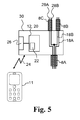
- Fig. 5 shows an exemplary control housing 30, e.g. of the audio device 102 in Fig. 4 .
- the control housing 30 accomodates the radio unit 12 and/or control unit 20.
- a user interface 26 is also accomodated in the control housing 30'.
- the fourth wire 28B is connected to the second wire 18B in the control housing and the primary part 8A has three wires connected to respective first, second and third terminals of the connector 10 which here is three-terminal connector.
- the third wire 28A and the fourth wire 28B may be omitted and the connector 10 may be a two-terminal connector.
- Fig. 6 shows an exemplary control housing 30', e.g. of the audio device 102 in Fig. 4 .
- the control housing 30' is similar to the control housing 30 in fig. 5 and additionally comprises a microphone 32 connected to a fifh wire 34A and a sixth wire 34B.
- the fifth wire 34A forms a part of the primary part 8A and is connected to a fourth terminal of the connector 10 which here is four-terminal connector.
- the audio device 102 with the control housing 30' is adapted for bi-directional audio communication via the primary part 8A of the cord 8.
- the second housing 14, the second secondary part 8C, the third wire 28A and the fourth wire 28B may be omitted and the connector 10 may be a three-terminal connector.
- the audio device may comprise a microphone that is mounted on a microphone arm attached, e.g. movably attached, to the first housing.
- the sixth wire may be connected to the second wire in the first housing.
- a microphone may be accommodated in the first housing or the second housing for bi-directional audio communication via the primary part of the cord.
- Fig. 7 illustrates an exemplary audio device according to the invention.
- the audio device 202 comprises a first housing 4", a second housing 14, a cord comprising a primary part 8A, a first secondary part 8B, and a second secondary part 8C.
- the primary part 8A has a first end with a connector 10 for connection to and receiving an audio signal from a media player 11.
- the audio device 202 comprises a control housing 30", e.g. as illustrated in Fig. 8 for sending wireless control information to the media player.
- Fig. 8 illustrates an exemplary control housing of an audio device.
- the control housing 30" accommodates a radio unit 12 and a user interface 26 for sending control information to a media player. Further, the control housing 30" accommodates a microphone 32 for bi-directional audio communication via the primay part 8A of the cord.
- Fig. 9 schematically illustrates an exemplary first housing of an audio device.
- a second secondary part 8C of the cord connects the first housing 4" to a second housing 14.
- the fourth wire 28B is connected to the second wire 18B in the first housing 4".
- Fig. 10 schematically illustrates an exemplary connector of an audio device.
- the connector 10 is a four-terminal connector, e.g. a TRRS (tip, ring, ring, sleeve). connector, and comprises a connector housing 35.
- the connector has a first terminal 36A connected to first wire 18A of the primary part 8A of the cord for connection to respective terminal of connector in a media player. Further, the connector has a second terminal 36B connected to second wire 18B, a third terminal 36C connected to third wire 28A and optionally a fourth terminal 36d connected to a fifth wire 34A.
- the number of terminals and wires in the connector and the primary part of the cord depends on the desired functionality and number of different parts of the audio device.
- the connector 10 may be a TRS connector (tip, ring, sleeve). It is cylindrical in shape, typically with three contacts or terminals, although sometimes with two (a TS connector) or four (a TRRS connector).
- the connector may be an audio jack, phone jack, phone plug, and jack plug. Specific models may be termed stereo plug, mini-jack, mini-stereo, headphone jack, tiny telephone connector and bantam plug.
- the male part of the connector may have a diameter of 3.5 mm or 2.5 mm.
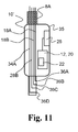
- Fig. 11 schematically illustrates an exemplary connector of an audio device.
- the connector 10' comprises a connector housing 35 accommodating a radio unit 12 and a user interface 26 for sending control information to a media player.
- One or more embodiments of the audio device may comprise the first housing 4" and connector 10'.
- Fig. 12 schematically illustrates a control unit 20.
- the control unit comprises a printed circuit board (PCB) 40 comprising wires for connecting different parts of the control unit.
- the control unit 20 comprises a radio unit 12 with a radio transmitter in form of a bluetooth low energy (BLE) chip 42 and an antenna 56 mounted on the PCB 40.
- BLE bluetooth low energy
- control unit 20 comprises a memory unit 44 connected to the BLE chip 42 via connection 46 comprising the necessary number of wires.
- the control unit comprises a number of switches 48, 50, 52, 54 connected to the BLE chip and forming a part of the user interface 26 thereby enabling a user to provide input to the BLE chip by activating the switches.
- the number of switches may be adapted to the desired number of input buttons.
- the antenna 56 is connected to the BLE chip in order to send radio signals to a media player.
- the control unit 20 also comprises a first clock unit 60 operating at a first frequency f 1 (e.g. about 8 MHz or about 16 MHz) and optionally a second clock unit 62 operating at a second frequency f 2 (e.g.
- the second clock unit 62 may be replaced by a downclocking circuit (not shown).
- the control circuit 20 may further comprise a first battery terminal 64A and a second battery terminal 64B for connection of a battery.
- control circuit comprises a detector unit 66 connected to the BLE chip.
- the detector circuit may be adapted to detect whether the audio device is connected or not (connection status).
- the BLE chip 42 may be adapted to send control information to the media player via the antenna based on the connection status of the audio device.
- a magnetic detection principle may be applied in the detector unit 66, e.g. by detecting signal activity between two wires in the audio device, e.g. the first wire and the second wire.
- Fig. 13 discloses a microphone housing for an audio device according to the invention, e.g. an audio device comprising a connector 10'.
- the microphone housing 80 is attached, mounted to or molded around the cord.
- the distance between the first housing and the microphone housing 80 along the cord, i.e. along the first secondary part 8B is in the range from 5 cm to about 40 cm, e.g. about 10 cm, about 15 cm or about 20 cm.
Landscapes
- Physics & Mathematics (AREA)
- Engineering & Computer Science (AREA)
- Acoustics & Sound (AREA)
- Signal Processing (AREA)
- Circuit For Audible Band Transducer (AREA)
- Details Of Audible-Bandwidth Transducers (AREA)
- Telephone Set Structure (AREA)
Abstract
Description
- The present invention relates to a corded audio device adapted for wireless data exchange with a media player or other communication device.
- The functionality of communication devices and audio devices, such as headphones and headsets, to be used with communication devices becomes increasingly advanced. Different manufacturers have developed their own connector standards for wired communication necessitating customized audio devices for different communication devices. The many different connector standards are cumbersome for the users and manufacturers.
- Wireless audio devices using different wireless communication protocols, such as Bluetooth, are known and require frequent recharging or exchange of batteries.
- Thus, there is a need for a user-friendly audio device that can be used for different communication devices.
- Accordingly, a corded audio device is provided, the audio device comprising a first housing; a first speaker for converting an electronic signal into sound, the first speaker being accommodated in the first housing; a cord with a connector for connection to and receiving an audio signal from a media player, the cord being connected to the first speaker; and a radio unit comprising a radio transmitter for sending control information to the media player. The control information may comprise identification data of the audio device.
- The audio device according to the present invention may be used for media players or other communication devices from different manufacturers using different standards for control signals. The combination of a radio unit and a cord enables wireless reading of audio device identifier or other audio device parameters and at the same time allows for use of a simple standard connector for connecting the audio device to a media player or other communication device.
- It is an advantage of the present invention that the battery requirements for the audio device may be limited, since only control information is sent wirelessly and audio signals are received and/or sent on a wired connection. Thus a more user-friendly audio device is provided since a user does not have to charge/replace batteries of the audio device on a regular basis.
- It is an advantage of the present invention that a media player or other communication device can adapt sound or audio parameters to the audio device based on an audio device identifier (identification data) and/or other control information from the audio device.
- It is an advantage of the present invention that the sound quality delivered to a user is not subjected to disadvantages related to radio transmission, such as interference problems.
- The above and other features and advantages of the present invention will become readily apparent to those skilled in the art by the following detailed description of exemplary embodiments thereof with reference to the attached drawings, in which:
- Fig. 1
- schematically illustrates an exemplary audio device according to the invention,
- Fig. 2
- schematically illustrates an exemplary first housing of an audio device,
- Fig. 3
- schematically illustrates an exemplary first or second housing of an audio device,
- Fig. 4
- schematically illustrates an exemplary audio device according to the invention,
- Fig. 5
- schematically illustrates an exemplary control housing of an audio device,
- Fig. 6
- schematically illustrates an exemplary control housing of an audio device,
- Fig. 7
- schematically illustrates an exemplary audio device according to the invention,
- Fig. 8
- schematically illustrates an exemplary control housing of an audio device,
- Fig. 9
- schematically illustrates an exemplary first housing of an audio device,
- Fig. 10
- schematically illustrates an exemplary connector of an audio device,
- Fig. 11
- schematically illustrates an exemplary connector of an audio device,
- Fig. 12
- schematically illustrates an exemplary control unit of an audio device, and
- Fig. 13
- schematically illustrates an exemplary microphone housing of an audio device.
- The figures are schematic and simplified for clarity, and they merely show details which are essential to the understanding of the invention, while other details may have been left out. Throughout, the same reference numerals are used for identical or corresponding parts.
- The audio device may be headphones, earphones, speakerphones (conferencing devices) or a headset.
- The media player may be a music or film player, mobile phone, a smart phone with or without a touch screen, or a tablet computer.
- The audio device comprises a first housing and a first speaker or first speakers for converting an electronic signal into sound. The first speaker may be accommodated in the first housing. The first housing may accommodate a single first speaker or a plurality of first speakers, e.g. including a first primary speaker and a first secondary speaker.
- Further, the audio device comprises a cord with a connector, e.g. for connection to and receiving an audio signal from a media player. The cord may comprise a primary part with a first end and a second end. The connector may be attached to the cord at the first end of the primary part. The cord may comprise one or more secondary parts, e.g. a first secondary part and/or a second secondary part, each having a first end and a second end. The cord may comprise a number of wires including a first wire and a second wire connecting one or more terminals of the connector to different parts of the audio device. The cord or parts thereof may be connected to the first speaker(s). The audio signal may be analog or digital. An analog audio signal from the media player may be fed directly to the first speaker(s) or a first speaker unit optionally including a filter unit. In one or more embodiments, an analog or digital audio signal from the media player may be fed to a first processing unit a common processing unit between the connector and the first speaker(s). The cord may comprise at least one or a plurality of wires connected to respective terminals of the connector. The cord may comprise a first wire connected to a first connector terminal and/or a second wire connected to a second connector terminal. The number of wires and terminals may be limited, e.g. the cord may comprise less than 5 wires. The number N of wires in the cord may be in the range from 1 to 4, e.g. N=2 or N=3, or N=4.
- The audio device comprises a radio unit comprising a radio transmitter for sending control information to the media player. Optionally, the control information comprises identification data of the audio device. The identification data of the audio device may comprise one or more of speaker performance data, e.g. speaker frequency response and/or speaker impedance, model number data, user interface data, and speaker sensitivity data. The media player may then be configured for selecting one or more audio signal parameters of the audio signal based on the identification data of the audio device.
- The audio device may comprise a control unit incorporating the radio unit. For example, a control unit may comprise a printed circuit board (PCB) with the radio unit mounted thereon. The radio unit may comprise or be constituted by a Bluetooth chip, such as a Blutooth Low Energy (BLE) Chip. The control unit may comprise one or more of at least one clock generator, an antenna and a memory. The antenna may be incorporated in the radio unit. The memory may store identification data of the audio device. The audio device may comprise first battery terminals connected to the radio unit, e.g. for feeding the radio unit and/or control unit. A first battery may be connected to or attached to the first battery terminals.
- The audio device may comprise a user interface enabling a user to provide user input to the audio device. The user interface may comprise one or more buttons, e.g. including a first button and optionally a second button. In one or more embodiments, the user interface has between two and ten buttons. The user interface may be connected to one or more input terminals of a control unit, e.g. directly to one or more input terminals of the radio unit or a BLE chip. The user interface may comprise a microphone and a voice command detection unit adapted for receiving and processing voice commands for voice control of the audio device. The user interface may comprise a connect button, where the audio device is adapted to send identification data of the audio device upon activation of the connect button.
- The audio device may be adapted to send control information to the media player based on the user input from the user interface. For example, the radio unit may be adapted to send a first control signal when a first button of the user interface is activated or pressed. The radio unit may comprise one or more antennas. Upon activation of different buttons of the userface, the audio device may be adapted to send different control signals to the media player, e.g. enabling a user to control the media player and operation thereof. The radio unit unit may be adapted for Bluetooth communication, e.g. according to the Bluetooth Low Energy (BLE) protocol.
- The audio device may comprise a control housing attached to the cord, wherein the user interface and/or the radio unit is/are arranged in the control housing. A control housing with user interface and radio unit attached to the cord may improve user friendliness of the audio device by facilitating user input during use. The control housing may be positioned at a distance from the first housing along the cord. The distance between the first housing and the control housing along the cord may be at least 5 cm, such as in the range from 5 cm to about 80 cm.
- The user interface and/or the radio unit may be arranged in the connector. A user interface and radio unit arranged in the connector may improve user friendliness of the audio device by facilitating user input during use.
- The user interface and/or the radio unit may be arranged in the first housing. A user interface and radio unit arranged in the first housing may provide a simple audio device with few complex parts, e.g. by incorporating movable parts into few or a single housing. This may lead to reduced assembly costs.
- There may be a need for controlling the audio device from the media player thereby improving the overall user experience. The radio unit may comprise a radio receiver for receiving control information from the media player.
- The control information to the media player may comprise control data or different control signals for the media player, e.g. control data or control signals indicative of one or more of the following: "VOLUME UP", "VOLUME DOWN", "CONNECT", "DISCONNECT", "NEXT", "PREVIOUS", "PLAY/PAUSE", "STOP".
- The audio device may comprise one or more battery compartments for accommodating one or more batteries for delivering power to the audio device. The audio device may comprise a set of battery charge terminals for allowing recharging of at least a first battery and/or a second battery.
- The audio device may comprise a second housing and a second speaker or second speakers for converting an electronic signal into sound. The second speaker(s) may be accommodated in the second housing. The second may accommodate a single second speaker or a plurality of second speakers, e.g. including a second primary speaker and a second secondary speaker.
- The cord may be connected to the second speaker(s). An analog audio signal from the media player may be fed directly to the second speaker(s) or a second speaker unit optionally including a filter unit. In one or more embodiments, an analog or digital audio signal from the media player may be fed to a second processing unit or to the common processing unit between the connector and the second speaker(s). The audio device may comprise second battery terminals, e.g. connected to processing unit, e.g. the first processing unit and/or the second processing unit. Second battery terminals may be connected to the common processing unit.
- The connector may be a two-terminal connector, a three-terminal connector, or a four-terminal connector. Accordingly, the number of terminals is relatively low, reducing the complexity of the connector.
- The audio device may be adapted for two-way audio communication. Accordingly, the audio device may comprise a microphone and the wherein the audio device may be configured for bi-directional or two-way audio communication via the cord.
- It may be desirable to reduce the number of required user input or user operations during setup or connecting the audio device. At the same time, it is desired to send identification data with as large time interval as possible in order to save power. Accordingly, the audio device may be adapted to detect connection status of the connector, i.e. whether the connector is plugged into a media player or not, and send control information to the media player via the radio unit based on the connection status. The audio device may thus comprise a detector unit for detecting connection status and adapted for activating the radio unit by triggering sending of identification data. In one or more embodiments, the radio unit is disabled when the connector is not connected as by the detector unit.
-
Fig. 1 schematically shows an audio device according to the present invention. Theaudio device 2 comprises afirst housing 4, a first speaker 6 for converting an electronic signal into sound, the first speaker 6 being accommodated in thefirst housing 4 as seen inFig. 2 . Theaudio device 2 has a cord 8 with aprimary part 8A having a first end with aconnector 10 for connection to and receiving an audio signal from amedia player 11, the cord 8 being connected to the first speaker 6. Further, theaudio device 2 comprises a radio unit 12 comprising a radio transmitter for sending control information to themedia player 11 on awireless connection 24, the control information comprising identification data of theaudio device 2. In the audio device inFig. 1 , the radio unit 12 is accommodated in thefirst housing 4 as seen inFig. 2 . Optionally, theaudio device 2 comprises asecond housing 14 accommodating a second speaker 16 as seen inFig. 3 connected to theconnector 10 via cord 8. The audio device may comprise a connecting band ordevice 17, such as a head band or neck band, connecting thefirst housing 4 and thesecond housing 14. A secondsecondary part part 8C may connect the second speaker 16 to theprimary part 8A. -
Fig. 2 schematically illustrates an exemplaryfirst housing 4 accommodating a first speaker 6. The first speaker 6 is connected to afirst wire 18A and asecond wire 18B of theprimary part 8A of the cord 8. Thewires connector 10 for receiving an audio signal from a media player. The radio unit 12 or acontrol unit 20 comprising the radio unit 12 is accommodated in thefirst housing 4. The radio unit 12 and/or thecontrol unit 20 comprises aradio transmitter 22 for sending control information to the media player over awireless connection 24. Further, auser interface 26, e.g. comprising one or more push buttons, is connected to the radio unit 12 and/orcontrol unit 20 thereby enabling a user to control the radio unit, e.g. by activating a first push button which will trigger sending identification data to themedia player 11. In anaudio device 2 with afirst housing 4, thesecond housing 14 with the second speaker 16, thethird wire 28A and thefourth wire 28B, and the secondsecondary part 8C may be omitted and theconnector 10 may be a two-terminal connector. The connectingband 17 may be omitted for anaudio device 2 where thefirst housing 4 and/or thesecond housing 14 are adapted for at least partly insertion into the ear canal. In anaudio device 2, thesecond housing 14, the secondsecondary part 8C, thethird wire 28A and thefourth wire 28B may be omitted and theconnector 10 may be a two-terminal connector. -
Fig. 3 illustrates an exemplary housing for use in the audio device, e.g.first housing 4 and/orsecond housing 14 accomodating a speaker 6, 16, respectively. The second speaker 16 may be connected to respective second and third terminals of theconnector 10 for receiving an audio signal from a media player viathird wire 28A andfourth wire 28B, respectively. Thefourth wire 28B may be connected to thesecond wire 18B. Accordingly, the cord 8 may be a three-wire cord with afirst wire 18A connected to a first terminal of theconnector 10 andthird wire 28A connected to a third terminal of the connector, the first and third wire acting as signal wires, the cord further comprising a common ground wire (second wire 18B) connected to a second terminal of the connector. -
Fig. 4 illustrates anexemplary audio device 102, e.g. of the earphone type. Theaudio device 102 comprises a first housing 4' and asecond housing 14, e.g. as illustrated inFig. 3 . The first housing 4' and thesecond housing 14 are in theaudio device 102 shaped for at least partly insertion into the ear canal of a user. Theprimary part 8A and the firstsecondary part 8B connect the first speaker 6 to a first terminal and a second terminal of theconnector 10. Theprimary part 8A and the secondsecondary part 8C connects the second speaker 16 to a second and third terminal of theconnector 10. Acontrol housing 30 is attached to the cord. The distance between the first housing 4' and thecontrol housing 30 along the cord, i.e. along the firstsecondary part 8B is about 20 cm. -
Fig. 5 shows anexemplary control housing 30, e.g. of theaudio device 102 inFig. 4 . Thecontrol housing 30 accomodates the radio unit 12 and/orcontrol unit 20. Auser interface 26 is also accomodated in the control housing 30'. Thefourth wire 28B is connected to thesecond wire 18B in the control housing and theprimary part 8A has three wires connected to respective first, second and third terminals of theconnector 10 which here is three-terminal connector. In anaudio device 102 with acontrol housing 30, thesecond housing 14, the secondsecondary part 8C, thethird wire 28A and thefourth wire 28B may be omitted and theconnector 10 may be a two-terminal connector. -
Fig. 6 shows an exemplary control housing 30', e.g. of theaudio device 102 inFig. 4 . The control housing 30' is similar to thecontrol housing 30 infig. 5 and additionally comprises amicrophone 32 connected to afifh wire 34A and asixth wire 34B. Thefifth wire 34A forms a part of theprimary part 8A and is connected to a fourth terminal of theconnector 10 which here is four-terminal connector. Theaudio device 102 with the control housing 30' is adapted for bi-directional audio communication via theprimary part 8A of the cord 8. In anaudio device 102 with a control housing 30', thesecond housing 14, the secondsecondary part 8C, thethird wire 28A and thefourth wire 28B may be omitted and theconnector 10 may be a three-terminal connector. - The audio device may comprise a microphone that is mounted on a microphone arm attached, e.g. movably attached, to the first housing. The sixth wire may be connected to the second wire in the first housing. A microphone may be accommodated in the first housing or the second housing for bi-directional audio communication via the primary part of the cord.
-
Fig. 7 illustrates an exemplary audio device according to the invention. Theaudio device 202 comprises afirst housing 4", asecond housing 14, a cord comprising aprimary part 8A, a firstsecondary part 8B, and a secondsecondary part 8C. Theprimary part 8A has a first end with aconnector 10 for connection to and receiving an audio signal from amedia player 11. Theaudio device 202 comprises acontrol housing 30", e.g. as illustrated inFig. 8 for sending wireless control information to the media player. -
Fig. 8 illustrates an exemplary control housing of an audio device. Thecontrol housing 30" accommodates a radio unit 12 and auser interface 26 for sending control information to a media player. Further, thecontrol housing 30" accommodates amicrophone 32 for bi-directional audio communication via theprimay part 8A of the cord. -
Fig. 9 schematically illustrates an exemplary first housing of an audio device. A secondsecondary part 8C of the cord connects thefirst housing 4" to asecond housing 14. Thefourth wire 28B is connected to thesecond wire 18B in thefirst housing 4". -
Fig. 10 schematically illustrates an exemplary connector of an audio device. Theconnector 10 is a four-terminal connector, e.g. a TRRS (tip, ring, ring, sleeve). connector, and comprises aconnector housing 35. The connector has afirst terminal 36A connected tofirst wire 18A of theprimary part 8A of the cord for connection to respective terminal of connector in a media player. Further, the connector has asecond terminal 36B connected tosecond wire 18B, athird terminal 36C connected tothird wire 28A and optionally a fourth terminal 36d connected to afifth wire 34A. The number of terminals and wires in the connector and the primary part of the cord depends on the desired functionality and number of different parts of the audio device. From a connection quality perspective, it may be desirable to keep the number of terminals to four or less. Theconnector 10 may be a TRS connector (tip, ring, sleeve). It is cylindrical in shape, typically with three contacts or terminals, although sometimes with two (a TS connector) or four (a TRRS connector). The connector may be an audio jack, phone jack, phone plug, and jack plug. Specific models may be termed stereo plug, mini-jack, mini-stereo, headphone jack, tiny telephone connector and bantam plug. The male part of the connector may have a diameter of 3.5 mm or 2.5 mm. -
Fig. 11 schematically illustrates an exemplary connector of an audio device. The connector 10' comprises aconnector housing 35 accommodating a radio unit 12 and auser interface 26 for sending control information to a media player. One or more embodiments of the audio device may comprise thefirst housing 4" and connector 10'. -
Fig. 12 schematically illustrates acontrol unit 20. The control unit comprises a printed circuit board (PCB) 40 comprising wires for connecting different parts of the control unit. Thecontrol unit 20 comprises a radio unit 12 with a radio transmitter in form of a bluetooth low energy (BLE)chip 42 and anantenna 56 mounted on thePCB 40. - Further, the
control unit 20 comprises amemory unit 44 connected to theBLE chip 42 viaconnection 46 comprising the necessary number of wires. The control unit comprises a number ofswitches user interface 26 thereby enabling a user to provide input to the BLE chip by activating the switches. The number of switches may be adapted to the desired number of input buttons. Theantenna 56 is connected to the BLE chip in order to send radio signals to a media player. Thecontrol unit 20 also comprises afirst clock unit 60 operating at a first frequency f1 (e.g. about 8 MHz or about 16 MHz) and optionally asecond clock unit 62 operating at a second frequency f2 (e.g. in the range from 10-40 KHz, such as about 32.8 KHz). Thesecond clock unit 62 may be replaced by a downclocking circuit (not shown). Thecontrol circuit 20 may further comprise afirst battery terminal 64A and asecond battery terminal 64B for connection of a battery. - Optionally, the control circuit comprises a
detector unit 66 connected to the BLE chip. The detector circuit may be adapted to detect whether the audio device is connected or not (connection status). TheBLE chip 42 may be adapted to send control information to the media player via the antenna based on the connection status of the audio device. A magnetic detection principle may be applied in thedetector unit 66, e.g. by detecting signal activity between two wires in the audio device, e.g. the first wire and the second wire. -
Fig. 13 discloses a microphone housing for an audio device according to the invention, e.g. an audio device comprising a connector 10'. Themicrophone housing 80 is attached, mounted to or molded around the cord. The distance between the first housing and themicrophone housing 80 along the cord, i.e. along the firstsecondary part 8B is in the range from 5 cm to about 40 cm, e.g. about 10 cm, about 15 cm or about 20 cm. - It should be noted that in addition to the exemplary embodiments of the invention shown in the accompanying drawings, the invention may be embodied in different forms and should not be construed as limited to the embodiments set forth herein. Rather, these embodiments are provided so that this disclosure will be thorough and complete, and will fully convey the concept of the invention to those skilled in the art.
-
- 2, 102, 202
- Audio device
- 4, 4', 4"
- First housing
- 6
- First speaker
- 8
- Cord
- 8A
- Primary part
- 8B
- First secondary part
- 8C
- Second secondary part
- 10
- Connector
- 11
- Media player
- 12
- Radio unit
- 14
- Second housing
- 16
- Second speaker
- 18A
- First wire
- 18B
- Second wire
- 20
-
Control unit 20 - 22
- Radio transmitter
- 24
- Wireless connection
- 26
- User interface
- 28A
- Third wire
- 28B
- Fourth wire
- 30, 30', 30"
- Control housing
- 32
- Microphone
- 34A
- Fifth wire
- 34B
- Sixth wire
- 35
- Connector housing
- 36A
- First terminal, First connector terminal
- 36B
- Second terminal, Second connector terminal
- 36C
- Third terminal, Third connector terminal
- 36D
- Fourth terminal, Fourth connector terminal
- 40
- PCB
- 42
- BLE chip
- 44
- Memory unit
- 46
- Connection
- 48
- First switch
- 50
- Second switch
- 52
- Third switch
- 54
- Fourth switch
- 56
- Antenna
- 60
- First clock unit
- 62
- Second clock unit
- 64A
- First battery terminal
- 64B
- Second battery terminal
- 66
- Detector unit
- 80
- Microphone housing
Claims (15)
- A corded audio device comprising
a first housing;
a first speaker for converting an electronic signal into sound, the first speaker being accommodated in the first housing;
a cord with a connector for connection to and receiving an audio signal from a media player, the cord being connected to the first speaker; and
a radio unit comprising a radio transmitter for sending control information to the media player, the control information comprising identification data of the audio device. - Audio device according to any of the preceding claims, wherein the audio device comprises a user interface enabling a user to provide user input to the audio device.
- Audio device according to claim 2, wherein the audio device is adapted to send control information to the media player based on the user input from the user interface.
- Audio device according to any of claims 2-3, comprising a control housing attached to the cord, wherein the user interface and/or the radio unit is/are arranged in the control housing.
- Audio device according to any of claims 2-3, wherein the user interface and/or the radio unit is/are arranged in the connector.
- Audio device according to any of claims 2-3, wherein the user interface and/or the radio unit is/are arranged in the first housing.
- Audio device according to any of the preceding claims, wherein the radio unit comprises a radio receiver for receiving control information from the media player.
- Audio device according to any of the preceding claims, wherein the identification data of the audio device comprises one or more of speaker performance data, model number data, user interface data, and speaker sensitivity data.
- Audio device according to any of the preceding claims, wherein the control information to the media player comprises control data for the media player.
- Audio device according to any of the preceding claims, comprising a battery compartment for accommodating a battery for delivering power to the audio device.
- Audio device according to any of the preceding claims, comprising a second housing and a second speaker for converting an electronic signal into sound, the second speaker being accommodated in the second housing and connected to the cord.
- Audio device according to any of the preceding claims, wherein the connector is a two-terminal connector, a three-terminal connector, or a four-terminal connector.
- Audio device according to any of the preceding claims, comprising a microphone and wherein the audio device is configured for bi-directional audio communication via the cord.
- Audio device according to any of the preceding claims, wherein the radio unit is adapted for Bluetooth communication, e.g. according to the Bluetooth Low Energy (BLE) protocol.
- Audio device according to any of the preceding claims, wherein the audio device is adapted to detect connection status of the connector and send control information to the media player via the radio unit based on the connection status.
Priority Applications (3)
| Application Number | Priority Date | Filing Date | Title |
|---|---|---|---|
| EP12161542.1A EP2645741A1 (en) | 2012-03-27 | 2012-03-27 | Corded audio device with wireless data exchange |
| US13/850,676 US20130259257A1 (en) | 2012-03-27 | 2013-03-26 | Corded audio device with wireless data exchange |
| CN2013101029286A CN103369419A (en) | 2012-03-27 | 2013-03-27 | Corded audio device |
Applications Claiming Priority (1)
| Application Number | Priority Date | Filing Date | Title |
|---|---|---|---|
| EP12161542.1A EP2645741A1 (en) | 2012-03-27 | 2012-03-27 | Corded audio device with wireless data exchange |
Publications (1)
| Publication Number | Publication Date |
|---|---|
| EP2645741A1 true EP2645741A1 (en) | 2013-10-02 |
Family
ID=46025343
Family Applications (1)
| Application Number | Title | Priority Date | Filing Date |
|---|---|---|---|
| EP12161542.1A Withdrawn EP2645741A1 (en) | 2012-03-27 | 2012-03-27 | Corded audio device with wireless data exchange |
Country Status (3)
| Country | Link |
|---|---|
| US (1) | US20130259257A1 (en) |
| EP (1) | EP2645741A1 (en) |
| CN (1) | CN103369419A (en) |
Families Citing this family (4)
| Publication number | Priority date | Publication date | Assignee | Title |
|---|---|---|---|---|
| US10171912B2 (en) | 2015-07-29 | 2019-01-01 | Hewlett-Packard Development Company, L.P. | Analog device connection |
| US20170155993A1 (en) * | 2015-11-30 | 2017-06-01 | Bragi GmbH | Wireless Earpieces Utilizing Graphene Based Microphones and Speakers |
| US20190342664A1 (en) * | 2018-05-03 | 2019-11-07 | Plantronics, Inc. | Control device with mute functionality for a headset audio system and headset audio system |
| US20190342650A1 (en) * | 2018-05-03 | 2019-11-07 | Plantronics, Inc. | Control device for a headset audio system and headset audio system |
Citations (2)
| Publication number | Priority date | Publication date | Assignee | Title |
|---|---|---|---|---|
| JP2001054184A (en) * | 1999-05-31 | 2001-02-23 | Toshiba Corp | Sound system and head mount sound device |
| US6233002B1 (en) * | 1997-09-25 | 2001-05-15 | Nec Corporation | Earphone system with operability improved and terminal equipment system with the earphone system |
Family Cites Families (4)
| Publication number | Priority date | Publication date | Assignee | Title |
|---|---|---|---|---|
| US5608700A (en) * | 1995-01-06 | 1997-03-04 | Ikeda; Takeshi | Remote controller having integrated circuit memory for recording and replaying signals from audio playback devices and/or external voice signals |
| CN101202787A (en) * | 2006-12-15 | 2008-06-18 | 英业达股份有限公司 | Electronic device |
| US8144915B2 (en) * | 2007-01-06 | 2012-03-27 | Apple Inc. | Wired headset with integrated switch |
| US20110110514A1 (en) * | 2009-11-09 | 2011-05-12 | Research In Motion Limited | Multi-button remote control headset with improved signaling |
-
2012
- 2012-03-27 EP EP12161542.1A patent/EP2645741A1/en not_active Withdrawn
-
2013
- 2013-03-26 US US13/850,676 patent/US20130259257A1/en not_active Abandoned
- 2013-03-27 CN CN2013101029286A patent/CN103369419A/en active Pending
Patent Citations (2)
| Publication number | Priority date | Publication date | Assignee | Title |
|---|---|---|---|---|
| US6233002B1 (en) * | 1997-09-25 | 2001-05-15 | Nec Corporation | Earphone system with operability improved and terminal equipment system with the earphone system |
| JP2001054184A (en) * | 1999-05-31 | 2001-02-23 | Toshiba Corp | Sound system and head mount sound device |
Also Published As
| Publication number | Publication date |
|---|---|
| US20130259257A1 (en) | 2013-10-03 |
| CN103369419A (en) | 2013-10-23 |
Similar Documents
| Publication | Publication Date | Title |
|---|---|---|
| US20170295421A1 (en) | Wireless earphone set | |
| EP2837206B1 (en) | Pulsed input push-to-talk systems, methods and apparatus | |
| JP2017123653A (en) | Wireless communication device | |
| CN107770663B (en) | In-ear wireless earphone and realization method for automatic charging and switching on/off of in-ear wireless earphone | |
| CN104581479B (en) | A kind of detachable wireless headphone system | |
| WO2012009984A1 (en) | Method and device for sharing micro-usb interface between earphone and usb | |
| CN206077633U (en) | A kind of In-Ear wireless headset | |
| EP2299669B1 (en) | Electronic device and system and method thereof for identifying electronic accessory and controlling electronic device | |
| EP3058752A1 (en) | Pulsed input push-to-talk wireless adapter systems and methods | |
| US9774152B2 (en) | Forward and backward compatible 5 pole audio plug and jack system | |
| CN103682724B (en) | Mobile terminal | |
| US11265934B2 (en) | Audio communication system with a dongle | |
| CN107770662B (en) | Automatic charging and switching circuit | |
| US20130259257A1 (en) | Corded audio device with wireless data exchange | |
| CN203909716U (en) | Novel mind headset | |
| EP3142382B1 (en) | Method, apparatus and system for supplying power to active noise cancelling earphone | |
| CN210536921U (en) | Multifunctional TWS Bluetooth earphone sound box | |
| CN103856865A (en) | Electronic device integrating earphone and loudspeaker | |
| US20170374447A1 (en) | Earbuds for use both wirelessly and with a wired connection | |
| CN213661872U (en) | Wireless earphone charging bin capable of clearing double-ear pairing records through one key | |
| CN208798187U (en) | A kind of adapter | |
| CN110401900A (en) | Headset connector | |
| CN205726246U (en) | A kind of bluetooth earphone of band interface | |
| CN110248271A (en) | The playback method being wirelessly transferred using wireless headset | |
| CN209861126U (en) | Multifunctional earphone |
Legal Events
| Date | Code | Title | Description |
|---|---|---|---|
| PUAI | Public reference made under article 153(3) epc to a published international application that has entered the european phase |
Free format text: ORIGINAL CODE: 0009012 |
|
| AK | Designated contracting states |
Kind code of ref document: A1 Designated state(s): AL AT BE BG CH CY CZ DE DK EE ES FI FR GB GR HR HU IE IS IT LI LT LU LV MC MK MT NL NO PL PT RO RS SE SI SK SM TR |
|
| AX | Request for extension of the european patent |
Extension state: BA ME |
|
| 17P | Request for examination filed |
Effective date: 20140402 |
|
| RBV | Designated contracting states (corrected) |
Designated state(s): AL AT BE BG CH CY CZ DE DK EE ES FI FR GB GR HR HU IE IS IT LI LT LU LV MC MK MT NL NO PL PT RO RS SE SI SK SM TR |
|
| STAA | Information on the status of an ep patent application or granted ep patent |
Free format text: STATUS: THE APPLICATION IS DEEMED TO BE WITHDRAWN |
|
| 18D | Application deemed to be withdrawn |
Effective date: 20140403 |