EP2645708A2 - Stripe noise correction method of captured image, photographing apparatus and electronic endoscopic apparatus - Google Patents
Stripe noise correction method of captured image, photographing apparatus and electronic endoscopic apparatus Download PDFInfo
- Publication number
- EP2645708A2 EP2645708A2 EP13161706.0A EP13161706A EP2645708A2 EP 2645708 A2 EP2645708 A2 EP 2645708A2 EP 13161706 A EP13161706 A EP 13161706A EP 2645708 A2 EP2645708 A2 EP 2645708A2
- Authority
- EP
- European Patent Office
- Prior art keywords
- image
- color
- correction
- pixels
- stripe noise
- Prior art date
- Legal status (The legal status is an assumption and is not a legal conclusion. Google has not performed a legal analysis and makes no representation as to the accuracy of the status listed.)
- Granted
Links
Images


Classifications
-
- H—ELECTRICITY
- H04—ELECTRIC COMMUNICATION TECHNIQUE
- H04N—PICTORIAL COMMUNICATION, e.g. TELEVISION
- H04N9/00—Details of colour television systems
- H04N9/64—Circuits for processing colour signals
- H04N9/646—Circuits for processing colour signals for image enhancement, e.g. vertical detail restoration, cross-colour elimination, contour correction, chrominance trapping filters
-
- H—ELECTRICITY
- H04—ELECTRIC COMMUNICATION TECHNIQUE
- H04N—PICTORIAL COMMUNICATION, e.g. TELEVISION
- H04N23/00—Cameras or camera modules comprising electronic image sensors; Control thereof
- H04N23/50—Constructional details
- H04N23/555—Constructional details for picking-up images in sites, inaccessible due to their dimensions or hazardous conditions, e.g. endoscopes or borescopes
-
- H—ELECTRICITY
- H04—ELECTRIC COMMUNICATION TECHNIQUE
- H04N—PICTORIAL COMMUNICATION, e.g. TELEVISION
- H04N25/00—Circuitry of solid-state image sensors [SSIS]; Control thereof
-
- H—ELECTRICITY
- H04—ELECTRIC COMMUNICATION TECHNIQUE
- H04N—PICTORIAL COMMUNICATION, e.g. TELEVISION
- H04N25/00—Circuitry of solid-state image sensors [SSIS]; Control thereof
- H04N25/60—Noise processing, e.g. detecting, correcting, reducing or removing noise
- H04N25/67—Noise processing, e.g. detecting, correcting, reducing or removing noise applied to fixed-pattern noise, e.g. non-uniformity of response
- H04N25/671—Noise processing, e.g. detecting, correcting, reducing or removing noise applied to fixed-pattern noise, e.g. non-uniformity of response for non-uniformity detection or correction
- H04N25/677—Noise processing, e.g. detecting, correcting, reducing or removing noise applied to fixed-pattern noise, e.g. non-uniformity of response for non-uniformity detection or correction for reducing the column or line fixed pattern noise
-
- G—PHYSICS
- G02—OPTICS
- G02F—OPTICAL DEVICES OR ARRANGEMENTS FOR THE CONTROL OF LIGHT BY MODIFICATION OF THE OPTICAL PROPERTIES OF THE MEDIA OF THE ELEMENTS INVOLVED THEREIN; NON-LINEAR OPTICS; FREQUENCY-CHANGING OF LIGHT; OPTICAL LOGIC ELEMENTS; OPTICAL ANALOGUE/DIGITAL CONVERTERS
- G02F1/00—Devices or arrangements for the control of the intensity, colour, phase, polarisation or direction of light arriving from an independent light source, e.g. switching, gating or modulating; Non-linear optics
- G02F1/01—Devices or arrangements for the control of the intensity, colour, phase, polarisation or direction of light arriving from an independent light source, e.g. switching, gating or modulating; Non-linear optics for the control of the intensity, phase, polarisation or colour
- G02F1/13—Devices or arrangements for the control of the intensity, colour, phase, polarisation or direction of light arriving from an independent light source, e.g. switching, gating or modulating; Non-linear optics for the control of the intensity, phase, polarisation or colour based on liquid crystals, e.g. single liquid crystal display cells
- G02F1/133—Constructional arrangements; Operation of liquid crystal cells; Circuit arrangements
- G02F1/1333—Constructional arrangements; Manufacturing methods
- G02F1/1347—Arrangement of liquid crystal layers or cells in which the final condition of one light beam is achieved by the addition of the effects of two or more layers or cells
- G02F1/13471—Arrangement of liquid crystal layers or cells in which the final condition of one light beam is achieved by the addition of the effects of two or more layers or cells in which all the liquid crystal cells or layers remain transparent, e.g. FLC, ECB, DAP, HAN, TN, STN, SBE-LC cells
- G02F1/13473—Arrangement of liquid crystal layers or cells in which the final condition of one light beam is achieved by the addition of the effects of two or more layers or cells in which all the liquid crystal cells or layers remain transparent, e.g. FLC, ECB, DAP, HAN, TN, STN, SBE-LC cells for wavelength filtering or for colour display without the use of colour mosaic filters
Definitions
- a solid-state imaging device for photographing a color image includes a plurality of pixels (photo-diodes) arranged on a semiconductor substrate in a two-dimensional array type. And, in the solid-state imaging device, a color filter is stacked on each of the pixels, and, for example, an amplifier or an analog/digital (A/D) convertor is provided in each pixel column.
- A/D analog/digital
- the image sensor of an electronic endoscopic apparatus is inserted into a body cavity, which is a dark place, and captures a subject image under insufficient illuminating light, which is illuminated to an affected part from a front end of an endoscopic scope via a slender light guide.
- the configuration of the signal read-out circuit that reads out the accumulated charges of each of the photo sensors of the solid-state imaging device 58 as an imaging signal is known, and a general configuration such as, for example, a three transistor configuration or a four transistor configuration may be applied thereto. The descriptions thereof will be omitted herein.
- the image data output from the DSP 86 is input to the display control circuit 88, and the display control circuit 88 converts the image data input from the DSP 86 into a signal format corresponding to the monitor 38 to be displayed to the screen of the monitor 38.
- a photographing apparatus of the exemplary embodiment includes: the image sensor set forth in any one as described above; the memory set forth in any one as described above; and an image processing unit that performs the stripe noise correction set forth in any one as described.
Landscapes
- Engineering & Computer Science (AREA)
- Multimedia (AREA)
- Signal Processing (AREA)
- Endoscopes (AREA)
- Instruments For Viewing The Inside Of Hollow Bodies (AREA)
- Transforming Light Signals Into Electric Signals (AREA)
- Closed-Circuit Television Systems (AREA)
Abstract
Description
- The present invention relates to a stripe noise correction method of a captured image, a photographing apparatus and an electronic endoscopic apparatus.
- A solid-state imaging device (an image sensor) for photographing a color image includes a plurality of pixels (photo-diodes) arranged on a semiconductor substrate in a two-dimensional array type. And, in the solid-state imaging device, a color filter is stacked on each of the pixels, and, for example, an amplifier or an analog/digital (A/D) convertor is provided in each pixel column.
- It is difficult to manufacture the amplifiers or the like, each of which is installed in the corresponding pixel column, to have the same performance, and a fluctuation in manufacture may occur. For this reason, a vertical stripe noise caused by the fluctuation in manufacture of the amplifiers or the like overlaps with a captured image of a subject. Since the vertical stripe noise deteriorates the image quality when the vertical stripe noise exists in a captured image, a correction processing is performed to reduce the vertical stripe noise. Although this example is described with the vertical stripe noise, a transverse stripe noise occurs when an amplifier or the like is provided in each pixel row. Although descriptions below are made with respect to the vertical stripe noise, the descriptions will be equally applied to the transverse stripe noise.
- Since a vertical stripe noise is a fixed pattern noise, an inherent vertical stripe noise component of a solid-state imaging device may be calculated in advance. When a subject is captured, the vertical stripe noise correction may be performed by subtracting the vertical stripe noise component from a real detection signal of each of the pixels. However, since the vertical stripe noise correction is performed in a digital signal processing, a portion below the decimal point of the vertical stripe noise component cannot be removed. Accordingly, a quantization error occurs. That is, the quantization error remains as a narrow vertical stripe noise.
- As disclosed in Patent Document 1 (
JP-B-4396757 JP-A-2005-167918 - The vertical stripe correction method discussed above has no problem when the method is applied to an image sensor mounted in a compact or single-lens reflex (SLR) digital camera. This is because the photographing is performed using a sunlight or a bright illuminating light as illuminating light.
- Under bright illuminating light, the absolute value of a signal amount S detected by each pixel is large. As a result, even when small random noise is overlapped, the noise component is less noticeable in the captured image.
- On the other hand, there is a problem in the vertical stripe noise correction of an image sensor used under a special environment. For example, the image sensor of an electronic endoscopic apparatus is inserted into a body cavity, which is a dark place, and captures a subject image under insufficient illuminating light, which is illuminated to an affected part from a front end of an endoscopic scope via a slender light guide.
- The insufficient illuminating light means that the absolute value of the signal amount S detected by each of the pixels is small, and the noise amount N is relatively increased. For this reason, the S/N (signal-to-noise ratio) is deteriorated as compared to an image sensor capable of using sunlight as illuminating light, and thus, the vertical stripe noise becomes noticeable.
- Specifically, an image captured by an electronic endoscopic apparatus is displayed on a monitor in a moving image format. Accordingly, when the vertical stripe noise overlaps on the same portion for every frame by the quantization error, the vertical stripe noise will more noticeable on the monitor image. With respect to the vertical stripe noise, even in white light observation other than the special light observation (narrow-band light observation), in which the wavelength band of the illuminating light is narrowed by weakening the illuminating light, fine vertical stripe noise becomes noticeable by performing an emphasizing processing to the observation image.
- The related art merely makes vertical stripe noise based on a quantization error noticeable by overlapping an artificially produced random noise, and does not remove a vertical stripe noise component caused by the quantization error. Further, the related art does not consider a method to remove vertical stripe noise with high precision from a single-plate image sensor for capturing a color image.
- An object of the present invention is to provide a stripe noise correction method of a captured image, a photographing apparatus, and an electronic endoscopic apparatus in which the stripe noise is capable of being removed with high precision from the image captured by a single-plate image sensor for capturing a color image even when the image sensor is used under a special environment.
- According to an aspect of the invention, a stripe noise correction method of a captured image includes: capturing, by a single-plate type image sensor for color image capturing that includes a plurality of pixels arranged in a square lattice array and a plurality of color filters with different colors which are respectively stacked on each of the pixels in a mosaic type, a plurality of images each of which has the same color with one of the colors of the color filters; calculating an average image for color images for the plurality of images and dividing the captured image signals of the average image into individual colors of the color filters; calculating, for each color, the stripe noise value for each pixel column or each pixel row by subtracting the average value of the captured image signals in the entire area where the pixels of the image sensor are arranged from the average value of the captured image signals of each pixel column or each pixel row of the image sensor; storing a value calculated by rounding off a portion below the decimal point of the stripe noise value into a memory as correction data of an integer part that corrects the stripe noise for each color; and storing the magnitude of a quantization error calculated by rounding off for each color and for each pixel column or each pixel row into the memory as correction data of a fractional part; and correcting the captured image signals of the image captured by the image sensor with the correction data of the integer part and the fractional part read from the memory.
- According to another aspect of the invention, a photographing apparatus includes: the aforementioned image sensor; the memory; and an image processing unit that performs the stripe noise correction.
- According to another aspect of the invention, an electronic endoscopic apparatus includes: an endoscopic scope that is inserted into a body cavity; the aforementioned image sensor that is accommodated in the front end part of the endoscopic scope; an illuminating unit that illuminates illuminating light from the front end part of the endoscopic scope; the memory; and an image processing unit that performs the stripe noise correction.
- With any one of the configurations discussed above, a stripe noise caused by a fluctuation in manufacturing a solid-state imaging device may be removed with high precision, thereby obtaining a captured image with high quality.
-
-
FIG. 1 is a system configuration view of an entire electronic endoscopic apparatus according to an exemplary embodiment of the present invention. -
FIG. 2 is a front view a front end surface of a front end part of the electronic endoscope illustrated inFIG. 1 . -
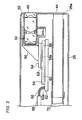
FIG. 3 is a longitudinal cross-sectional view of the front end part of the electronic endoscope illustrated inFIG. 1 . -
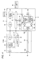
FIG. 4 is a block configuration diagram of a control system of the electronic endoscopic apparatus illustrated inFIG. 1 . -
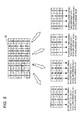
FIG. 5 is an explanatory diagram for calculating vertical stripe noise for each of four colors (Gr, Gb, R, B) with a solid-state imaging device of which the color filter arrangement is a Bayer array. -
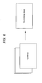
FIG. 6 is an explanatory diagram of a color image when a profile of a vertical stripe noise is calculated. -
FIG. 7 is a characteristic diagram of a low-frequency noise removed vertical stripe noise. -
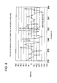
FIG. 8 is a characteristic diagram illustrating residue data after corrected with vertical stripe correction data of an integer part. -
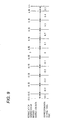
FIG. 9 is an explanatory diagram of vertical stripe correction data of a fractional part. -
FIG. 10 is an explanatory diagram in a case where vertical stripe correction data of a fractional part is performed. -
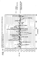
FIG. 11 is a characteristic diagram illustrating an effect when the vertical stripe correction in a fractional part is performed. - Hereinafter, an exemplary embodiment of the present invention will be described with reference to the accompanying drawings.
-
FIG. 1 is a system configuration view of an entire electronic endoscopic apparatus according to an exemplary embodiment of the present invention. The electronic endoscopic apparatus (endoscope system) 10 of the present exemplary embodiment includes anendoscopic scope 12, and aprocessor device 14 and alight source device 16 that constitute a main body apparatus. Theendoscopic scope 12 includes aflexible inserting unit 20 that is inserted into a body cavity of a patient (a subject), a manipulatingunit 22 installed to be connected with a base end of theinserting unit 20, and auniversal cord 24 that is connected with theprocessor device 14 and thelight source device 16. - A front-
end part 26 is continuously formed in the front-end of theinserting unit 20, an imaging chip 54 (an imaging device seeFIG. 3 ) for photographing the inside of the body cavity is accommodated in the front-end part 26. Acurved unit 28 formed by connecting a plurality of curved pieces is installed in the rear of the front-end part 26. Thecurved unit 28 is curvedly operated in the up-down and left-right directions by pushing/pulling a wire provided by being inserted within theinserting unit 20 when anangle knob 30 installed in the manipulatingunit 22 is manipulated. Therefore, the front-end part 26 faces a desired direction within the body cavity. - A
connector 36 is installed in the base end of theuniversal cord 24. Theconnector 36 is a complex type, and is connected to thelight source device 16 as well as theprocessor device 14. - The
processor device 14 supplies power to theendoscopic scope 12 via a cable 68 (seeFIG. 3 ) inserted through theuniversal cord 24 to control the driving of theimaging chip 54, and at the same time, theprocessor device 14 receives an imaging signal transmitted from theimaging chip 54 via thecable 68, and performs various signal processings on the received imaging signal to convert into image data. - The image data converted in the
processor device 14 is displayed in amonitor 38 as an endoscopic photographing image (an observation image). Themonitor 38 is connected to theprocessor device 14 with a cable. Theprocessor device 14 is also electrically connected to thelight source device 16 via theconnector 36, and generally controls the operations of the electronicendoscopic apparatus 10 including thelight source device 16. -
FIG. 2 is a front view illustrating a front-end surface 26a of the front-end part 26 of theendoscopic scope 12. As illustrated inFIG. 2 , anobservation window 40, illuminatingwindows 42, aforceps outlet 44, an air/water transferring nozzle 46 are formed in the front-end surface 26a of the front-end part 26. - The
observation window 40 is arranged at a center part of the front-end surface 26a and a position offset from the center of the front-end surface 26a. Two illuminatingwindows 42 are arranged in symmetric locations with respect to theobservation window 40, and illuminate the light from thelight source device 16 to the portion to be observed within the body cavity. - The
forceps outlet 44 is connected to a forceps channel 70 (See,FIG. 3 ) arranged within the insertingunit 20, and is communicated with a forceps inlet 34 (seeFIG. 1 ) installed in the manipulatingunit 22. Various treatment tools, of which front-ends are provided with, for example, an injection needle or a high frequency mess, are inserted through theforceps inlet 34, and the front-ends of the various treatment tools come out from theforceps outlet 44 and into the body cavity. - The air/
water transferring nozzle 46 sprays cleaning water or air supplied from an air/water transferring device accommodated in thelight source device 16 toward the inside of the body cavity or theobservation window 40 according to the manipulation of an air/water transferring button 32 (seeFIG. 1 ) installed in the manipulatingunit 22. -
FIG. 3 is a view illustrating the longitudinal cross-section of the front-end part 26 of theendoscopic scope 12. As illustrated inFIG. 3 , abarrel 52 is disposed inside theobservation window 40. Thebarrel 52 holds an objectoptical system 50 to receive an image light of a portion to be observed within the body cavity. Thebarrel 52 is attached such that the optic axis of the objectoptical system 50 is parallel to the center axis of the insertingunit 20. Aprism 56 is connected to the rear end of thebarrel 52. Theprism 56 guides a light such that the image light of the portion to be observed is bent through the objectoptical system 50 at right angles to be directed to theimaging chip 54. - The
imaging chip 54 is a monolithic semiconductor (a sensor chip) which is integrally formed with a solid-state imaging device 58 and aperipheral circuit 60 that performs the driving and the input/output of the signals of the solid-state imaging device 58. Theimaging chip 54 is mounted on asupport substrate 62. - The imaging surface (light-receiving surface) 58a of the solid-
state imaging device 58 is arranged to face an exit surface of theprism 56. A rectangular plate shapedcover glass 64 is attached on theimaging surface 58a via a rectangular frame shapedspacer 63. Theimaging chip 54, thespacer 63 and thecover glass 64 are assembled using an adhesive, and as a result, theimaging surface 58a is protected from the infiltration of dust or the like. - A plurality of input/
output terminals 62a are installed side by side in the width direction in the rear end of thesupport substrate 62 installed to extend toward the rear end of the insertingunit 20. The input/output terminals 62a are connected to signallines 66 to exchange various signals with theprocessor device 14 through theuniversal cord 24, and are electrically connected to theperipheral circuit 60 within theimaging chip 54 through, for example, wirings or bonding pads (not illustrated) formed in thesupport substrate 62. - The signal lines 66 are integrally inserted within a
flexible tubular cable 68. Thecable 68 is inserted into the inside of each of the insertingunit 20, the manipulatingunit 22 and theuniversal cord 24, and is connected to theconnector 36. - Although not illustrated in
FIGS. 2 and3 , an illuminating unit is installed in the inner side of the illuminatingwindows 42. Theexit end 120a of a light guide 120 (seeFIG. 4 ) that guides the illuminating lights from thelight source device 16 is disposed in the illuminating unit, and theexit end 120a is installed to face the illuminatingwindows 42. Thelight guide 120 is inserted into the inside of each of the insertingunit 20, the manipulatingunit 22 and theuniversal cord 24, like thecable 68, and is connected to theconnector 36 at the incident end thereof. -
FIG. 4 is a block diagram illustrating a control system of the electronicendoscopic apparatus 10. As illustrated inFIG. 4 , theimaging device 58, an analog signal processing circuit (an analog front end; AFE) 72, a timing generator (TG) 78, and aCPU 80 are installed in thefront end part 26 of theendoscopic scope 12. TheAFE 72 or theTG 78 corresponds to theperipheral circuit 60 inFIG. 3 . TheCPU 80 is connected to amemory 81 such as, for example, an EEPROM. The vertical stripe correction data of the solid-state imaging device 58 is preserved in thememory 81. - The
TG 78 generates a driving pulse (for example, a vertical/horizontal scan pulse and a reset pulse) of the solid-state imaging device 58 and a synchronized pulse for theAFE 72, based on the control of theCPU 80. The solid-state imaging device 58 is driven according to the driving pulse inputted from theTG 78, and photoelectrically converts the optical shape imaged on theimaging surface 58a through the objectoptical system 50 to output as an imaging signal. - A plurality of pixels are arranged in a matrix type in the
imaging surface 58a of the solid-state imaging device 58, and a photo sensor (photoelectric conversion device) is installed in each of the pixels. The light incident to theimaging surface 58a of the solid-state imaging device 58 is accumulated in the photo sensor of each of the pixels as electrical charges. The signal electrical charges accumulated in the photo sensor of each of the pixels are sequentially read out as pixel signals and output in a predetermined frame rate by vertical and horizontal scanning using a vertical scan circuit and a horizontal scan circuit (both not illustrated). - The solid-
state imaging device 58 is a single-plate color imaging type solid-state imaging device including color filters (for example, primary color filters in a Bayer array) formed by a plurality of color segments. - The configuration of the signal read-out circuit that reads out the accumulated charges of each of the photo sensors of the solid-
state imaging device 58 as an imaging signal is known, and a general configuration such as, for example, a three transistor configuration or a four transistor configuration may be applied thereto. The descriptions thereof will be omitted herein. - The
AFE 72 is constituted by a correlated double sampling (CDS) circuit, an automatic gain circuit (AGC), and an A/D converter. The CDS circuit performs a correlated double sampling processing with respect to an imaging signal outputted from the solid-state imaging device 58 to remove an amp noise and a reset noise generated from the solid-state imaging device 58. TheAFE 72 is provided for each of the columns of the solid-state imaging device 58. - The AGC amplifies the imaging signal of which the noise is removed by the CDS circuit to a gain (amplifying rate) designated from the
CPU 80. The A/D converter converts the imaging signal amplified by the AGC into a digital signal in a predetermined bit number, and outputs the converted signal. The imaging signal (digital imaging signal) digitalized and output from theAFE 72 is input to theprocessor device 14 via the signal lines 66. - The
processor device 14 is configured to include theCPU 82, aROM 84, aRAM 85, an image processing circuit (DSP) 86, and adisplay control circuit 88. - The
CPU 82 controls each part of theprocessor device 14, and at the same time, generally controls the entire electronicendoscopic apparatus 10. Various programs to control the operations of theprocessor device 14 or control data are stored in advance in theROM 84. For example, programs executed by theCPU 82 or data are temporarily stored in theRAM 85. - The
DSP 86 performs, for example, a vertical stripe noise correction processing, a color interpolation, a color separation, a color balance adjustment, a gamma adjustment, and an image enhancement processing to generate an image data with respect to the imaging signal imputed from theAFE 72 based on the control of theCPU 82. - The image data output from the
DSP 86 is input to thedisplay control circuit 88, and thedisplay control circuit 88 converts the image data input from theDSP 86 into a signal format corresponding to themonitor 38 to be displayed to the screen of themonitor 38. - The manipulating
unit 90 of theprocessor device 14 is provided with a mode conversion button to select or convert the operation modes of the solid-state imaging device 58, or various buttons to receive other instruction inputs from user. - The
light source device 16 is configured to include a mainlight source 100, a main lightsource driving circuit 101, a speciallight source 102, a special lightsource driving circuit 103, aCPU 104, and amultiplexer unit 105. TheCPU 104 communicates with theCPU 82 of theprocessor device 14 to control the main lightsource driving circuit 101 and the special lightsource driving circuit 103. - The main
light source 100 emits a white light, and the speciallight source 102 emits a special light of a narrow band of which the center is, for example, 420 nm. The white light or the special light exits to theincident end 120b of thelight guide 120 through themultiplexer unit 105. - When the inside of a body cavity is observed with the electronic
endoscopic apparatus 10 as described above, theendoscopic scope 12, theprocessor device 14, thelight source device 16, and themonitor 38 are turned ON, the insertingunit 20 of theendoscopic scope 12 is inserted into the body cavity. A moving image in the inside of the body cavity captured by the solid-state imaging device 58 is observed through themonitor 38 while illuminating the inside of the body cavity using the illuminating light from thelight source device 16. - When an image to be displayed in the
monitor 38 is generated, theDSP 86 receives captured image signals (an RAW signals) outputted from the solid-state imaging device 58 and performs vertical stripe correction for each of the colors. Then, theDSP 86 performs known various image processings such as, for example, a synchronization processing (de-mosaic processing), a gamma correction processing and an RGB/YC conversion processing to the captured image signals of each pixel position after the vertical stripe correction, thereby generating an image to be displayed on themonitor 38. - In the present exemplary embodiment, the vertical stripe correction data used when performing the vertical stripe correction is determined in the following manner, and is stored in the
memory 81. - The upper part of
FIG. 5 is a schematic view of a surface of the solid-state imaging device 58. Three primary color filters of R (red), G (green), and B (blue) are arranged in a Bayer array in the solid-state imaging device 58 in which a plurality of pixels are arranged in a square lattice array. In the present exemplary embodiment, a green (G) filter adjacent to a pixel equipped with an R filter in a transverse direction (row direction) is set to a "Gr", and a green (G) filter adjacent to a pixel equipped with a B filter in the transverse direction is set to a "Gb". The Gr and Gb are the same in color, but are treated as having different colors when the vertical stripe correction data are calculated. - About 10 single color images of red (R), green (G), and blue (B) are captured using the solid-
state imaging device 58, and a detection value of each of the pixels of an average image thereof is calculated, as illustrated inFIG. 6 . - Next, as illustrated in
FIG. 5 , each of the images is divided into color surfaces of four colors of R, Gr, Gb, and B, and an average value (total average value) of the pixel detection values of the entire area for each of the colors (R, Gr, Gb, B) is calculated. Separately, an average value (column average value) of the detection values of the individual pixels aligned in the same vertical direction (column direction) is calculated for each of the colors (R, Gr, Gb, B). - Then, "a column average value - a total average value" is calculated for each of the colors (R, Gr, Gb, B) and for each of the pixel columns. A data group of the "column average values - total average values" for each of the colors and for each of the pixel columns forms a profile of a vertical stripe strength.
- It is not only the values of the vertical stripe noise that are included in the profile of the vertical stripe strength.
FIG. 8 is a graph illustrating a profile of the vertical stripe strength of, for example, Gr color. The transverse axis indicates a transverse position (column coordinate position) of the solid-state imaging device 58, and the vertical axis indicates the value of the vertical stripe strength. - The removal of the vertical stripe noise may be performed, for example, as below. In the Bayer array illustrated in the upper part of
FIG. 5 , columns where Gr colors and B colors are aligned and columns where Gb colors and R colors are aligned are alternately arranged. A value of a Gr color which is calculated by subtracting the vertical stripe correction data for the Gr color at the pixel column position from a real Gr pixel detection value detected from the pixel column of Gr colors and B colors, is set to a Gr pixel detection value after the vertical stripe correction. The same calculation will be performed with respect to the B colors, Gb colors, and R colors. - Even if such vertical stripe noise correction is performed, a vertical stripe may appear in sight in the observation image in an observation performed under a special environment, for example, such as an electronic endoscope. This is believed due to an effect of the quantization error by rounding off below the decimal point.
- Hereinafter, the correction to remove the effect of the quantization error will be described. That is, how to perform the correction of the fractional part equal to or less than ±0.5 by rounding off below the decimal point will be described.
-
FIG. 8 is a graph illustrating a vertical strip strength distribution after the vertical stripe correction of the captured image using the vertical stripe correction data of an integer. That is, it is a graph illustrating residue data after the correction by an integer part. The transverse axis is the coordinate of a pixel column position, and the vertical axis is the residue strength of a vertical stripe. - Since the portion below the decimal point is rounded off, the residue of a vertical stripe is within the range of -0.5 to +0.5. However, the amplitude of the residue strength of the vertical stripe may theoretically become "1" in its maximum. For this reason, the residue equal to or less than ±0.5 needs to be corrected to be smaller in order to perform the vertical stripe correction with higher precision.
- Therefore, in the present exemplary embodiment, the vertical stripe correction data of a fractional part may be assigned to residue data after the residue data is corrected by the vertical stripe correction data of an integer, as illustrated in
FIG. 9 . The assignment of the vertical stripe correction data of the fractional part is determined based on the following viewpoint of (a). - (a) In comparison of an image and residue data after correction by the vertical stripe correction data of an integer, the vertical stripe of which the residue is equal to or less than about ±0.05 (the maximum amplitude is 0.1) is not remarkably noticeable.
- From the viewpoint (a), the correction data of
FIG. 9 are set forth as below. The correction data are set to eleven vertical stripe correction data: "0" when the residue data is "-0.05 to +0.05", "0.1" when the residue data is "0.05 to 0.15", "0.2" when the residue data is "0.15 to 0.25", "0.3" when the residue data is "0.25 to 0.35", "0.4" when the residue data is "0.35 to 0.45", "0.5" when the residue data is "0.45 to 0.5", "-0.1" when the residue data is "-0.05 to -0.15", "-0.2" when the residue data is "-0.15 to -0.25", "-0.3" when the residue data is "-0.25 to -0.35", "-0.4" when the residue data is "-0.35 to -0.45", and "-0.5" when the residue data is "-0.45 to -0.5". Meanwhile, how to assign the correction data of a fractional part for residue data is not limited to the example ofFIG. 9 . -
FIG. 10 is an explanatory diagram of a correction method by correction data of a fractional part. Like the correction using vertical stripe correction data of an integer part as described above, the correction using the vertical stripe correction data of a fractional part is also performed after a captured image signal is converted into digital data by an A/D converter. For this reason, the correction of a portion below the decimal point cannot be performed as it is. That is, the addition and subtraction of, for example, "0.3" cannot be performed for a pixel detection value after the correction of the integer part. Therefore, for example, when the correction of "0.3" for Gr color in the pixel column thereof is performed, the Gr pixels belonging to the pixel column are subtracted by "1" in a ratio of three pixels to ten pixels. Therefore, it becomes equivalent to the case where the ten pixels are subtracted by "0.3" on average. In this way, the correction of each of "±0.1", "±0.2", "±0.3", "±0.4" and "±0.5" is performed as illustrated inFIG. 10 . - Such correction is performed for every frame of a moving image. Pixels to be subtracted by the value "1" whenever frames are changed may be selected randomly using, for example, random numbers rather than being fixed. As a result of simulation, it was found out that the results are the same regardless of whether the pixels to be subtracted are fixed or randomly selected. However, it is believed that the correction through the random selection is more stable. The user may be allowed to select either method.
-
FIG. 11 is a graph illustrating an effect by performing the correction of a fractional part. The characteristic graph I represents the effect when only the vertical stripe correction of an integer part was performed (as inFIG. 8 ), and the residue data of a vertical stripe of "±0.5" remain. In contrast, the characteristic graph II is a graph when the vertical stripe correction of an integer part and the vertical stripe correction of a fractional part are both performed. The residue data of a vertical stripe become equal to or less than "±0.05" as illustrated in (a), so that the vertical stripe becomes noticeable. - As described above, in the present exemplary embodiment, when the vertical stripe noise is removed for each color of the color filters stacked in the image sensor, the vertical stripe correction data of an integer part is calculated for each of the colors by rounding off below the decimal point, and the vertical stripe correction data of a fractional part below the decimal point is calculated for each of the colors, so that the correction is performed using both data. Accordingly, even in an observation image under a special environment as an electronic endoscope, it is possible to make the visibility of the observation image good.
- Meanwhile, even if the known noise reduction processing performed by comparing prior and post images is performed, there is no effect to the vertical stripe noise correction result of the present exemplary embodiment. For this reason, the noise reduction processing may be jointly used in order to reduce a noise component other than the vertical stripe noise.
- As described above, although the vertical stripe correction of an image captured by a CMOS type imaging device accommodated in a front end part of an electronic endoscopic apparatus has been disclosed as an example, the present invention, of course, may be applied to the vertical stripe correction of an image captured by a CMOS type or CCD type imaging device mounted in, for example, a general digital camera and a video camera. Further, of course, the above-described exemplary embodiments may be applied to a transverse stripe noise.
- As described above, the stripe noise correction method of a captured image according to the present exemplary embodiment includes: capturing, by a single-plate type image sensor for color image capturing that includes a plurality of pixels arranged in a square lattice array and a plurality of color filters with different colors which are respectively stacked on each of the pixels in a mosaic type, a plurality of images each of which has the same color with one of the colors of the color filters; calculating an average image for color images for the plurality of images and dividing the captured image signals of the average image into individual colors of the color filters; calculating, for each color, the stripe noise value for each pixel column or each pixel row by subtracting the average value of the captured image signals in the entire area where the pixels of the image sensor are arranged from the average value of the captured image signals of each pixel column or each pixel row of the image sensor; storing a value calculated by rounding off a portion below the decimal point of the stripe noise value into a memory as correction data of an integer part that corrects the stripe noise for each color; and storing the magnitude of a quantization error calculated by rounding off for each color and for each pixel column or each pixel row into the memory as correction data of a fractional part; and correcting the captured image signals of the image captured by the image sensor with the correction data of the integer part and the fractional part read from the memory.
- In the stripe noise correction method of the captured image of the exemplary embodiment, when the magnitude of the quantization error which is rounded off below the decimal point is n/m where m and n are positive integers and m>n, the values of n pixels among m pixels of the pixel column or the pixel row are subtracted by "1" and the values of the remaining (m-n) pixels are not subtracted to perform the correction based on the correction data of the fractional part.
- In the stripe noise correction method of the captured image of the exemplary embodiment, how to select the n pixels among the m pixels is randomly changed for each frame of the captured image which is a moving image.
- A photographing apparatus of the exemplary embodiment includes: the image sensor set forth in any one as described above; the memory set forth in any one as described above; and an image processing unit that performs the stripe noise correction set forth in any one as described.
- An electronic endoscopic apparatus of the exemplary embodiment includes: an endoscopic scope that is inserted into a body cavity; the image sensor that is accommodated in the front end part of the endoscopic scope and set forth in any one as described above; an illuminating unit that illuminates illuminating light from the front end part of the endoscopic scope; the memory set forth in any one as described above; and an image processing unit that performs the stripe noise correction set forth in any one as described above.
- In the electronic endoscopic apparatus of the exemplary embodiment, the illuminating unit illuminates a special light of a narrow band as the illuminating light.
- According to the exemplary emodiments as described above, the stripe noise may be removed with high precision, and thus a high quality of captured image may be obtained.
- The stripe noise correction method according to the present invention may correct the stripe noise of the captued image in a high precision, and may be effectualy applid to, for example, a digital camera, a digital video camera, a handheld phone with a camera, an electronic equimpment with a camera, and an electronic endoscope.
Claims (6)
- A stripe noise correction method of a captured image comprising:capturing, by a single-plate type image sensor for color image capturing that includes a plurality of pixels arranged in a square lattice array and a plurality of color filters with different colors which are respectively stacked on each of the pixels in a mosaic type, a plurality of images each of which has the same color with one of the colors of the color filters;calculating an average image for color images for the plurality of images and dividing the captured image signals of the average image into individual colors of the color filters;calculating, for each color, the stripe noise value for each pixel column or each pixel row by subtracting the average value of the captured image signals in the entire area where the pixels of the image sensor are arranged from the average value of the captured image signals of each pixel column or each pixel row of the image sensor;storing a value calculated by rounding off a portion below the decimal point of the stripe noise value into a memory as correction data of an integer part that corrects the stripe noise for each color; and storing the magnitude of a quantization error calculated by rounding off for each color and for each pixel column or each pixel row into the memory as correction data of a fractional part; andcorrecting the captured image signals of the image captured by the image sensor with the correction data of the integer part and the fractional part read from the memory.
- The stripe noise correction method of claim 1, wherein,
when the magnitude of the quantization error which is rounded off below the decimal point is n/m where m and n are positive integers and m>n, the values of n pixels among m pixels of the pixel column or the pixel row are subtracted by "1" and the values of the remaining (m-n) pixels are not subtracted to perform the correction based on the correction data of the fractional part. - The stripe correction method of claim 2, wherein,
how to select the n pixels among the m pixels is randomly changed for each frame of the captured image which is a moving image. - A photographing apparatus comprising:the image sensor according to any one of claims 1 to 3;the memory; andan image processing unit that performs the stripe noise correction.
- An electronic endoscopic apparatus comprising:an endoscopic scope that is inserted into a body cavity;the image sensor that is accommodated in the front end part of the endoscopic scope according to any one of claims 1 to 3;an illuminating unit that illuminates illuminating light from the front end part of the endoscopic scope;the memory; andan image processing unit that performs the stripe noise correction.
- The electronic endoscopic apparatus of claim 5, wherein,
the illuminating unit illuminates a special light of a narrow band as the illuminating light.
Applications Claiming Priority (1)
| Application Number | Priority Date | Filing Date | Title |
|---|---|---|---|
| JP2012080680A JP5648010B2 (en) | 2012-03-30 | 2012-03-30 | Device operating method, photographing apparatus and electronic endoscope apparatus |
Publications (3)
| Publication Number | Publication Date |
|---|---|
| EP2645708A2 true EP2645708A2 (en) | 2013-10-02 |
| EP2645708A3 EP2645708A3 (en) | 2017-02-22 |
| EP2645708B1 EP2645708B1 (en) | 2018-01-10 |
Family
ID=48092696
Family Applications (1)
| Application Number | Title | Priority Date | Filing Date |
|---|---|---|---|
| EP13161706.0A Not-in-force EP2645708B1 (en) | 2012-03-30 | 2013-03-28 | Stripe noise correction method of captured image, photographing apparatus and electronic endoscopic apparatus |
Country Status (3)
| Country | Link |
|---|---|
| US (1) | US9282302B2 (en) |
| EP (1) | EP2645708B1 (en) |
| JP (1) | JP5648010B2 (en) |
Cited By (4)
| Publication number | Priority date | Publication date | Assignee | Title |
|---|---|---|---|---|
| CN105828692A (en) * | 2013-12-20 | 2016-08-03 | 奥林巴斯株式会社 | Endoscopic device |
| CN111028179A (en) * | 2019-12-20 | 2020-04-17 | 浙江大华技术股份有限公司 | Stripe correction method and device, electronic equipment and storage medium |
| CN112565637A (en) * | 2020-11-20 | 2021-03-26 | 中国航空工业集团公司洛阳电光设备研究所 | Method for removing stripe noise under low illumination in single-color sCMOS camera |
| CN116055902A (en) * | 2022-12-30 | 2023-05-02 | 深圳锐视智芯科技有限公司 | Image generation method and device, image sensor and storage medium |
Families Citing this family (9)
| Publication number | Priority date | Publication date | Assignee | Title |
|---|---|---|---|---|
| CN103679648B (en) * | 2013-11-18 | 2016-07-27 | 北京空间机电研究所 | A kind of match by moment satellite image Strip noise removal method based on space segmentation |
| JP6196900B2 (en) * | 2013-12-18 | 2017-09-13 | オリンパス株式会社 | Endoscope device |
| WO2015093295A1 (en) * | 2013-12-20 | 2015-06-25 | オリンパス株式会社 | Endoscopic device |
| CN106127705A (en) * | 2016-06-22 | 2016-11-16 | 成都市晶林科技有限公司 | Infrared image goes horizontal stripe processing method |
| CN106815820B (en) * | 2017-01-24 | 2019-09-10 | 西安科技大学 | A kind of infrared image strip noise cancellation method |
| JP6832250B2 (en) * | 2017-07-18 | 2021-02-24 | オリンパス株式会社 | Endoscope, controller, correction method and program |
| CN110910324B (en) * | 2019-11-19 | 2023-04-14 | 山东神戎电子股份有限公司 | Method for removing vertical stripes in infrared video |
| CN113465544B (en) * | 2021-06-25 | 2022-04-08 | 安徽农业大学 | Stripe projection three-dimensional measurement nonlinear error correction method |
| CN121101392A (en) * | 2025-11-14 | 2025-12-12 | 杭州巨星科技股份有限公司 | Vacuum cleaner |
Citations (2)
| Publication number | Priority date | Publication date | Assignee | Title |
|---|---|---|---|---|
| JP2005167918A (en) | 2003-12-05 | 2005-06-23 | Sony Corp | Solid-state imaging device and imaging method |
| JP4396757B2 (en) | 2007-10-22 | 2010-01-13 | ソニー株式会社 | Noise correction circuit, imaging apparatus, and noise correction method |
Family Cites Families (16)
| Publication number | Priority date | Publication date | Assignee | Title |
|---|---|---|---|---|
| CA1194987A (en) * | 1981-09-30 | 1985-10-08 | Yasuo Takemura | Solid-state color television camera |
| DE3482366D1 (en) * | 1983-07-21 | 1990-06-28 | Victor Company Of Japan | COLOR TELEVISION CAMERA WITH TWO OR MORE FIXED BODY IMAGING DEVICES. |
| JP2000137172A (en) * | 1998-10-29 | 2000-05-16 | Olympus Optical Co Ltd | Image pickup device |
| JP4107029B2 (en) * | 2002-09-20 | 2008-06-25 | 富士ゼロックス株式会社 | Image reading device |
| JP3972302B2 (en) * | 2003-03-26 | 2007-09-05 | ソニー株式会社 | Image sensor |
| JP4379006B2 (en) * | 2003-06-04 | 2009-12-09 | 株式会社ニコン | Imaging device |
| JP4340503B2 (en) * | 2003-09-18 | 2009-10-07 | 株式会社リコー | Document reader |
| JP4027340B2 (en) * | 2004-04-20 | 2007-12-26 | キヤノン株式会社 | Imaging apparatus and imaging method |
| JP4661168B2 (en) * | 2004-11-02 | 2011-03-30 | ソニー株式会社 | Signal processing apparatus and method for solid-state imaging device, and imaging apparatus |
| JP4341528B2 (en) * | 2004-11-02 | 2009-10-07 | ソニー株式会社 | Signal processing apparatus and method for solid-state imaging device, and imaging apparatus |
| US7456384B2 (en) * | 2004-12-10 | 2008-11-25 | Sony Corporation | Method and apparatus for acquiring physical information, method for manufacturing semiconductor device including array of plurality of unit components for detecting physical quantity distribution, light-receiving device and manufacturing method therefor, and solid-state imaging device and manufacturing method therefor |
| JP2007053691A (en) * | 2005-08-19 | 2007-03-01 | Micron Technol Inc | Extended digital data path structure using sub-LSB |
| EP2007131B1 (en) * | 2006-04-07 | 2013-02-27 | Mitsubishi Electric Corporation | Noise elimination apparatus and noise elimination method |
| JP4238900B2 (en) * | 2006-08-31 | 2009-03-18 | ソニー株式会社 | Solid-state imaging device, imaging device |
| JP5124492B2 (en) * | 2009-01-08 | 2013-01-23 | Hoya株式会社 | Fixed pattern noise elimination unit, imaging unit, and electronic endoscope system |
| CN102984989B (en) * | 2010-08-30 | 2015-08-19 | 奥林巴斯医疗株式会社 | Endoscope apparatus |
-
2012
- 2012-03-30 JP JP2012080680A patent/JP5648010B2/en active Active
-
2013
- 2013-03-28 EP EP13161706.0A patent/EP2645708B1/en not_active Not-in-force
- 2013-03-29 US US13/853,696 patent/US9282302B2/en active Active
Patent Citations (2)
| Publication number | Priority date | Publication date | Assignee | Title |
|---|---|---|---|---|
| JP2005167918A (en) | 2003-12-05 | 2005-06-23 | Sony Corp | Solid-state imaging device and imaging method |
| JP4396757B2 (en) | 2007-10-22 | 2010-01-13 | ソニー株式会社 | Noise correction circuit, imaging apparatus, and noise correction method |
Cited By (7)
| Publication number | Priority date | Publication date | Assignee | Title |
|---|---|---|---|---|
| CN105828692A (en) * | 2013-12-20 | 2016-08-03 | 奥林巴斯株式会社 | Endoscopic device |
| CN105828692B (en) * | 2013-12-20 | 2018-01-23 | 奥林巴斯株式会社 | Endoscope apparatus |
| CN111028179A (en) * | 2019-12-20 | 2020-04-17 | 浙江大华技术股份有限公司 | Stripe correction method and device, electronic equipment and storage medium |
| CN111028179B (en) * | 2019-12-20 | 2023-04-28 | 浙江大华技术股份有限公司 | Stripe correction method and device, electronic equipment and storage medium |
| CN112565637A (en) * | 2020-11-20 | 2021-03-26 | 中国航空工业集团公司洛阳电光设备研究所 | Method for removing stripe noise under low illumination in single-color sCMOS camera |
| CN112565637B (en) * | 2020-11-20 | 2022-07-29 | 中国航空工业集团公司洛阳电光设备研究所 | Method for removing stripe noise under low illumination in monochromatic sCMOS camera |
| CN116055902A (en) * | 2022-12-30 | 2023-05-02 | 深圳锐视智芯科技有限公司 | Image generation method and device, image sensor and storage medium |
Also Published As
| Publication number | Publication date |
|---|---|
| JP2013208284A (en) | 2013-10-10 |
| EP2645708A3 (en) | 2017-02-22 |
| EP2645708B1 (en) | 2018-01-10 |
| JP5648010B2 (en) | 2015-01-07 |
| US9282302B2 (en) | 2016-03-08 |
| US20130258082A1 (en) | 2013-10-03 |
Similar Documents
| Publication | Publication Date | Title |
|---|---|---|
| EP2645708B1 (en) | Stripe noise correction method of captured image, photographing apparatus and electronic endoscopic apparatus | |
| JP5245022B1 (en) | Imaging device | |
| CN102740760B (en) | Endoscope device | |
| JP5847017B2 (en) | Electronic endoscope apparatus and method for operating the same | |
| JPWO2012073729A1 (en) | Imaging apparatus and focus position detection method thereof | |
| US20100277625A1 (en) | Image processing apparatus, imaging apparatus, method of correction coefficient calculation, and storage medium storing image processing program | |
| US10602919B2 (en) | Imaging device | |
| JP6442362B2 (en) | Image pickup apparatus and image pickup element control method | |
| JP2012143319A (en) | Endoscope system and method for driving the same | |
| JP2012217486A (en) | Endoscope system and driving method thereof | |
| US9113045B2 (en) | Electronic endoscopic apparatus and control method thereof | |
| JP2004229055A (en) | Image processing device | |
| JP5734060B2 (en) | Endoscope system and driving method thereof | |
| JP5827868B2 (en) | Electronic endoscope and fixed pattern noise removal method | |
| KR101809476B1 (en) | Image processing device | |
| JP2013126002A (en) | Endoscope device | |
| WO2019123600A1 (en) | Image capture device | |
| JP2010239192A (en) | Solid-state imaging device, imaging apparatus, and image signal processing method | |
| JP6277138B2 (en) | Endoscope system and operating method thereof | |
| JP5156560B2 (en) | Electronic endoscope system | |
| JP6589071B2 (en) | Imaging device, endoscope and endoscope system | |
| JP4199044B2 (en) | Imaging apparatus and control method thereof | |
| JP6312254B2 (en) | Endoscope system and operating method thereof | |
| JP6005794B2 (en) | Endoscope system and driving method thereof | |
| JP2008258786A (en) | Brightness signal generating method and brightness signal generating device, and focus detecting method and focus detecting device in imaging apparatus |
Legal Events
| Date | Code | Title | Description |
|---|---|---|---|
| PUAI | Public reference made under article 153(3) epc to a published international application that has entered the european phase |
Free format text: ORIGINAL CODE: 0009012 |
|
| AK | Designated contracting states |
Kind code of ref document: A2 Designated state(s): AL AT BE BG CH CY CZ DE DK EE ES FI FR GB GR HR HU IE IS IT LI LT LU LV MC MK MT NL NO PL PT RO RS SE SI SK SM TR |
|
| AX | Request for extension of the european patent |
Extension state: BA ME |
|
| PUAL | Search report despatched |
Free format text: ORIGINAL CODE: 0009013 |
|
| AK | Designated contracting states |
Kind code of ref document: A3 Designated state(s): AL AT BE BG CH CY CZ DE DK EE ES FI FR GB GR HR HU IE IS IT LI LT LU LV MC MK MT NL NO PL PT RO RS SE SI SK SM TR |
|
| AX | Request for extension of the european patent |
Extension state: BA ME |
|
| RIC1 | Information provided on ipc code assigned before grant |
Ipc: H04N 5/335 20110101AFI20170119BHEP Ipc: H04N 5/225 20060101ALN20170119BHEP Ipc: H04N 5/365 20110101ALI20170119BHEP |
|
| STAA | Information on the status of an ep patent application or granted ep patent |
Free format text: STATUS: REQUEST FOR EXAMINATION WAS MADE |
|
| 17P | Request for examination filed |
Effective date: 20170518 |
|
| RBV | Designated contracting states (corrected) |
Designated state(s): AL AT BE BG CH CY CZ DE DK EE ES FI FR GB GR HR HU IE IS IT LI LT LU LV MC MK MT NL NO PL PT RO RS SE SI SK SM TR |
|
| GRAP | Despatch of communication of intention to grant a patent |
Free format text: ORIGINAL CODE: EPIDOSNIGR1 |
|
| STAA | Information on the status of an ep patent application or granted ep patent |
Free format text: STATUS: GRANT OF PATENT IS INTENDED |
|
| RIC1 | Information provided on ipc code assigned before grant |
Ipc: H04N 5/225 20060101ALN20170719BHEP Ipc: H04N 9/64 20060101ALI20170719BHEP Ipc: H04N 5/335 20110101AFI20170719BHEP Ipc: H04N 5/365 20110101ALI20170719BHEP |
|
| INTG | Intention to grant announced |
Effective date: 20170811 |
|
| GRAS | Grant fee paid |
Free format text: ORIGINAL CODE: EPIDOSNIGR3 |
|
| GRAA | (expected) grant |
Free format text: ORIGINAL CODE: 0009210 |
|
| STAA | Information on the status of an ep patent application or granted ep patent |
Free format text: STATUS: THE PATENT HAS BEEN GRANTED |
|
| AK | Designated contracting states |
Kind code of ref document: B1 Designated state(s): AL AT BE BG CH CY CZ DE DK EE ES FI FR GB GR HR HU IE IS IT LI LT LU LV MC MK MT NL NO PL PT RO RS SE SI SK SM TR |
|
| REG | Reference to a national code |
Ref country code: CH Ref legal event code: EP Ref country code: AT Ref legal event code: REF Ref document number: 963639 Country of ref document: AT Kind code of ref document: T Effective date: 20180115 |
|
| REG | Reference to a national code |
Ref country code: IE Ref legal event code: FG4D |
|
| REG | Reference to a national code |
Ref country code: DE Ref legal event code: R096 Ref document number: 602013031870 Country of ref document: DE |
|
| REG | Reference to a national code |
Ref country code: FR Ref legal event code: PLFP Year of fee payment: 6 |
|
| REG | Reference to a national code |
Ref country code: NL Ref legal event code: MP Effective date: 20180110 |
|
| REG | Reference to a national code |
Ref country code: AT Ref legal event code: MK05 Ref document number: 963639 Country of ref document: AT Kind code of ref document: T Effective date: 20180110 |
|
| PG25 | Lapsed in a contracting state [announced via postgrant information from national office to epo] |
Ref country code: NL Free format text: LAPSE BECAUSE OF FAILURE TO SUBMIT A TRANSLATION OF THE DESCRIPTION OR TO PAY THE FEE WITHIN THE PRESCRIBED TIME-LIMIT Effective date: 20180110 |
|
| PG25 | Lapsed in a contracting state [announced via postgrant information from national office to epo] |
Ref country code: LT Free format text: LAPSE BECAUSE OF FAILURE TO SUBMIT A TRANSLATION OF THE DESCRIPTION OR TO PAY THE FEE WITHIN THE PRESCRIBED TIME-LIMIT Effective date: 20180110 Ref country code: ES Free format text: LAPSE BECAUSE OF FAILURE TO SUBMIT A TRANSLATION OF THE DESCRIPTION OR TO PAY THE FEE WITHIN THE PRESCRIBED TIME-LIMIT Effective date: 20180110 Ref country code: NO Free format text: LAPSE BECAUSE OF FAILURE TO SUBMIT A TRANSLATION OF THE DESCRIPTION OR TO PAY THE FEE WITHIN THE PRESCRIBED TIME-LIMIT Effective date: 20180410 Ref country code: HR Free format text: LAPSE BECAUSE OF FAILURE TO SUBMIT A TRANSLATION OF THE DESCRIPTION OR TO PAY THE FEE WITHIN THE PRESCRIBED TIME-LIMIT Effective date: 20180110 Ref country code: FI Free format text: LAPSE BECAUSE OF FAILURE TO SUBMIT A TRANSLATION OF THE DESCRIPTION OR TO PAY THE FEE WITHIN THE PRESCRIBED TIME-LIMIT Effective date: 20180110 Ref country code: CY Free format text: LAPSE BECAUSE OF FAILURE TO SUBMIT A TRANSLATION OF THE DESCRIPTION OR TO PAY THE FEE WITHIN THE PRESCRIBED TIME-LIMIT Effective date: 20180110 |
|
| PG25 | Lapsed in a contracting state [announced via postgrant information from national office to epo] |
Ref country code: LV Free format text: LAPSE BECAUSE OF FAILURE TO SUBMIT A TRANSLATION OF THE DESCRIPTION OR TO PAY THE FEE WITHIN THE PRESCRIBED TIME-LIMIT Effective date: 20180110 Ref country code: SE Free format text: LAPSE BECAUSE OF FAILURE TO SUBMIT A TRANSLATION OF THE DESCRIPTION OR TO PAY THE FEE WITHIN THE PRESCRIBED TIME-LIMIT Effective date: 20180110 Ref country code: GR Free format text: LAPSE BECAUSE OF FAILURE TO SUBMIT A TRANSLATION OF THE DESCRIPTION OR TO PAY THE FEE WITHIN THE PRESCRIBED TIME-LIMIT Effective date: 20180411 Ref country code: PL Free format text: LAPSE BECAUSE OF FAILURE TO SUBMIT A TRANSLATION OF THE DESCRIPTION OR TO PAY THE FEE WITHIN THE PRESCRIBED TIME-LIMIT Effective date: 20180110 Ref country code: IS Free format text: LAPSE BECAUSE OF FAILURE TO SUBMIT A TRANSLATION OF THE DESCRIPTION OR TO PAY THE FEE WITHIN THE PRESCRIBED TIME-LIMIT Effective date: 20180510 Ref country code: BG Free format text: LAPSE BECAUSE OF FAILURE TO SUBMIT A TRANSLATION OF THE DESCRIPTION OR TO PAY THE FEE WITHIN THE PRESCRIBED TIME-LIMIT Effective date: 20180410 Ref country code: RS Free format text: LAPSE BECAUSE OF FAILURE TO SUBMIT A TRANSLATION OF THE DESCRIPTION OR TO PAY THE FEE WITHIN THE PRESCRIBED TIME-LIMIT Effective date: 20180110 Ref country code: AT Free format text: LAPSE BECAUSE OF FAILURE TO SUBMIT A TRANSLATION OF THE DESCRIPTION OR TO PAY THE FEE WITHIN THE PRESCRIBED TIME-LIMIT Effective date: 20180110 |
|
| REG | Reference to a national code |
Ref country code: DE Ref legal event code: R097 Ref document number: 602013031870 Country of ref document: DE |
|
| PG25 | Lapsed in a contracting state [announced via postgrant information from national office to epo] |
Ref country code: AL Free format text: LAPSE BECAUSE OF FAILURE TO SUBMIT A TRANSLATION OF THE DESCRIPTION OR TO PAY THE FEE WITHIN THE PRESCRIBED TIME-LIMIT Effective date: 20180110 Ref country code: IT Free format text: LAPSE BECAUSE OF FAILURE TO SUBMIT A TRANSLATION OF THE DESCRIPTION OR TO PAY THE FEE WITHIN THE PRESCRIBED TIME-LIMIT Effective date: 20180110 Ref country code: EE Free format text: LAPSE BECAUSE OF FAILURE TO SUBMIT A TRANSLATION OF THE DESCRIPTION OR TO PAY THE FEE WITHIN THE PRESCRIBED TIME-LIMIT Effective date: 20180110 Ref country code: RO Free format text: LAPSE BECAUSE OF FAILURE TO SUBMIT A TRANSLATION OF THE DESCRIPTION OR TO PAY THE FEE WITHIN THE PRESCRIBED TIME-LIMIT Effective date: 20180110 |
|
| REG | Reference to a national code |
Ref country code: CH Ref legal event code: PL |
|
| PLBE | No opposition filed within time limit |
Free format text: ORIGINAL CODE: 0009261 |
|
| STAA | Information on the status of an ep patent application or granted ep patent |
Free format text: STATUS: NO OPPOSITION FILED WITHIN TIME LIMIT |
|
| PG25 | Lapsed in a contracting state [announced via postgrant information from national office to epo] |
Ref country code: SK Free format text: LAPSE BECAUSE OF FAILURE TO SUBMIT A TRANSLATION OF THE DESCRIPTION OR TO PAY THE FEE WITHIN THE PRESCRIBED TIME-LIMIT Effective date: 20180110 Ref country code: SM Free format text: LAPSE BECAUSE OF FAILURE TO SUBMIT A TRANSLATION OF THE DESCRIPTION OR TO PAY THE FEE WITHIN THE PRESCRIBED TIME-LIMIT Effective date: 20180110 Ref country code: CZ Free format text: LAPSE BECAUSE OF FAILURE TO SUBMIT A TRANSLATION OF THE DESCRIPTION OR TO PAY THE FEE WITHIN THE PRESCRIBED TIME-LIMIT Effective date: 20180110 Ref country code: MC Free format text: LAPSE BECAUSE OF FAILURE TO SUBMIT A TRANSLATION OF THE DESCRIPTION OR TO PAY THE FEE WITHIN THE PRESCRIBED TIME-LIMIT Effective date: 20180110 Ref country code: DK Free format text: LAPSE BECAUSE OF FAILURE TO SUBMIT A TRANSLATION OF THE DESCRIPTION OR TO PAY THE FEE WITHIN THE PRESCRIBED TIME-LIMIT Effective date: 20180110 |
|
| REG | Reference to a national code |
Ref country code: BE Ref legal event code: MM Effective date: 20180331 |
|
| 26N | No opposition filed |
Effective date: 20181011 |
|
| REG | Reference to a national code |
Ref country code: IE Ref legal event code: MM4A |
|
| PG25 | Lapsed in a contracting state [announced via postgrant information from national office to epo] |
Ref country code: LU Free format text: LAPSE BECAUSE OF NON-PAYMENT OF DUE FEES Effective date: 20180328 |
|
| PG25 | Lapsed in a contracting state [announced via postgrant information from national office to epo] |
Ref country code: IE Free format text: LAPSE BECAUSE OF NON-PAYMENT OF DUE FEES Effective date: 20180328 |
|
| PG25 | Lapsed in a contracting state [announced via postgrant information from national office to epo] |
Ref country code: CH Free format text: LAPSE BECAUSE OF NON-PAYMENT OF DUE FEES Effective date: 20180331 Ref country code: BE Free format text: LAPSE BECAUSE OF NON-PAYMENT OF DUE FEES Effective date: 20180331 Ref country code: SI Free format text: LAPSE BECAUSE OF FAILURE TO SUBMIT A TRANSLATION OF THE DESCRIPTION OR TO PAY THE FEE WITHIN THE PRESCRIBED TIME-LIMIT Effective date: 20180110 Ref country code: LI Free format text: LAPSE BECAUSE OF NON-PAYMENT OF DUE FEES Effective date: 20180331 |
|
| PGFP | Annual fee paid to national office [announced via postgrant information from national office to epo] |
Ref country code: GB Payment date: 20190327 Year of fee payment: 7 |
|
| PG25 | Lapsed in a contracting state [announced via postgrant information from national office to epo] |
Ref country code: MT Free format text: LAPSE BECAUSE OF NON-PAYMENT OF DUE FEES Effective date: 20180328 |
|
| PG25 | Lapsed in a contracting state [announced via postgrant information from national office to epo] |
Ref country code: TR Free format text: LAPSE BECAUSE OF FAILURE TO SUBMIT A TRANSLATION OF THE DESCRIPTION OR TO PAY THE FEE WITHIN THE PRESCRIBED TIME-LIMIT Effective date: 20180110 |
|
| PG25 | Lapsed in a contracting state [announced via postgrant information from national office to epo] |
Ref country code: PT Free format text: LAPSE BECAUSE OF FAILURE TO SUBMIT A TRANSLATION OF THE DESCRIPTION OR TO PAY THE FEE WITHIN THE PRESCRIBED TIME-LIMIT Effective date: 20180110 Ref country code: HU Free format text: LAPSE BECAUSE OF FAILURE TO SUBMIT A TRANSLATION OF THE DESCRIPTION OR TO PAY THE FEE WITHIN THE PRESCRIBED TIME-LIMIT; INVALID AB INITIO Effective date: 20130328 |
|
| PG25 | Lapsed in a contracting state [announced via postgrant information from national office to epo] |
Ref country code: MK Free format text: LAPSE BECAUSE OF NON-PAYMENT OF DUE FEES Effective date: 20180110 |
|
| PGFP | Annual fee paid to national office [announced via postgrant information from national office to epo] |
Ref country code: FR Payment date: 20200214 Year of fee payment: 8 |
|
| GBPC | Gb: european patent ceased through non-payment of renewal fee |
Effective date: 20200328 |
|
| PG25 | Lapsed in a contracting state [announced via postgrant information from national office to epo] |
Ref country code: GB Free format text: LAPSE BECAUSE OF NON-PAYMENT OF DUE FEES Effective date: 20200328 |
|
| PG25 | Lapsed in a contracting state [announced via postgrant information from national office to epo] |
Ref country code: FR Free format text: LAPSE BECAUSE OF NON-PAYMENT OF DUE FEES Effective date: 20210331 |
|
| REG | Reference to a national code |
Ref country code: DE Ref legal event code: R079 Ref document number: 602013031870 Country of ref document: DE Free format text: PREVIOUS MAIN CLASS: H04N0005335000 Ipc: H04N0025000000 |
|
| P01 | Opt-out of the competence of the unified patent court (upc) registered |
Effective date: 20230515 |
|
| PGFP | Annual fee paid to national office [announced via postgrant information from national office to epo] |
Ref country code: DE Payment date: 20240130 Year of fee payment: 12 |
|
| REG | Reference to a national code |
Ref country code: DE Ref legal event code: R119 Ref document number: 602013031870 Country of ref document: DE |
|
| PG25 | Lapsed in a contracting state [announced via postgrant information from national office to epo] |
Ref country code: DE Free format text: LAPSE BECAUSE OF NON-PAYMENT OF DUE FEES Effective date: 20251001 |